

FUJIFILM FinePix A120 SERVICE MANUAL

FinePix A120
US/CA/EU/EG/GE/AS-MODEL
SERVICE MANUAL
WARNING
THE COMPORNENTS IDENTIFIED BY THE MARK “ ” ON THE SCHEMATHIC
DIAGRAM AND IN THE PARTS LIST ARE CRITICAL FOR SAFETY.
PLEASE REPLACE ONLY BY THE COMPONENTS SPECIFIED ON THE SCHEMATHIC
DIAGRAM AND IN THE PARTS LIST.
IF YOU USE PARTS NOT SPECIFIED, IT MAY RESULT IN A FIRE AND AN
ELECTORICAL SHOCK.
FUJI PHOTO FILM CO.,LTD.
Printed in Japan 2004.04(H.I.)
Ref.No.:ZM00539-101
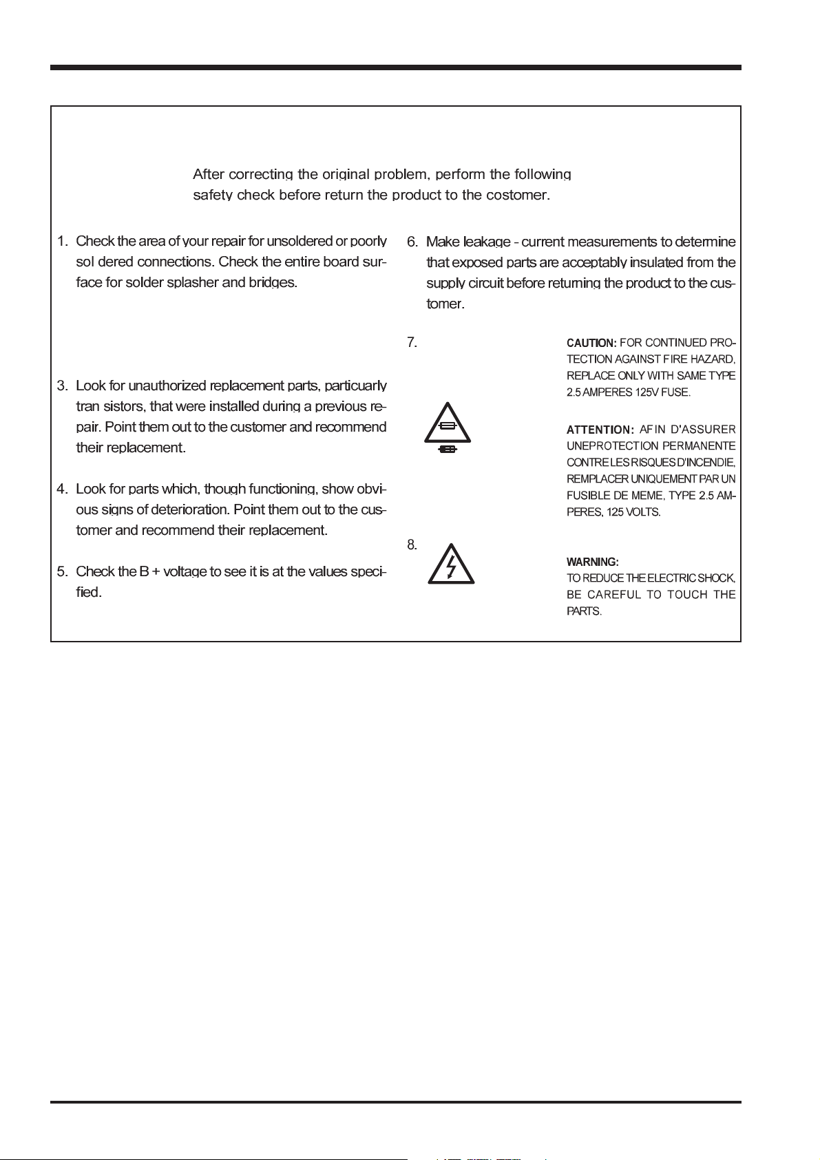
SAFETY CHECK-OUT
2. Check the interboard wiring to ensure that no wires
are “pinched” or contact high-wattage resistors.
Fine Pix A120 SERVICE MANUAL
2.5A 125V
2.5A 125V
RISK OF FIREREPLACE FUSE
AS MARKED
WARNING!
HIGH VOLTAGE
2

Fine Pix A120 SERVICE MANUAL
TABLE OF CONTENTS
1.General .................................................... 4
1-1.Product specification............................................... 4
1-2.Explanation of Terms............................................... 6
1-3.Names of External Components ............................. 7
2.Disassembly............................................. 8
2-1.Name of Internal Parts ............................................ 8
2-2.How to Disassemble the CABI REAR ASSY. ......... 9
2-3.How to Disassemble the BATERY HOLDER. ......... 9
2-4.How to Disassemble the LCD UNIT. ..................... 10
2-5.How to Disassemble the INNER BLOCK.............. 10
2-6.How to Disassemble the MAIN PWB. .................... 11
2-7.How to Disassemble the ENGIN PWB. ................ 12
2-8.How to Disassemble the CABI FRONT................. 1 2
2-9.How to Disassemble of BARIA ASSY. ................... 13
2-10.Location of Sheet Parts....................................... 14
2-10-1.EMI SHEET(FZ05858-100).............................. 14
2-10-2.EMI SHEET (FZ05857-100)............................. 14
2-10-3.EMI SHEET (FZ05856-100)............................. 14
2-10-4.K TAPE 1(RELESE SWICH)............................ 15
2-10-5.K TAPE 2(RELESE SWICH)............................ 15
2-10-6.K TAPE 3(MAIN PWB)..................................... 15
2-10-7.UL TAPE 1(MAIN FRAME)............................... 16
4.Adjustment ............................................. 27
4-1.Important point Adjustment when Replacing Major Parts ... 27
4-2.Measuring Instruments Used ................................ 27
4-3.Use Jig list............................................................. 27
4-4.Jig Connections .................................................... 28
4-5.Environmental Setup............................................. 28
4-6.Installing the Jig Drivers on the PC....................... 30
4-7.Installing and Starting the Adjustment Software ... 30
4-8. Initial Settings of the Adjustment Software .......... 31
4-9. Starting the Adjustment Software......................... 34
4-10.[F4]:CCD Defect Data Input ................................ 36
4-11.[F5]:CAM Adjustment .......................................... 38
4-12.[F7]:Flash Adjustment ......................................... 40
4-13.[F1]:Battery Adjustment....................................... 41
4-14.[F11]:Video Adjustment ....................................... 45
4-15. [F3] LCD Adjustment......................................... 47
4-16. [F12] : End Setting ............................................. 48
4-17.[F8]:Firmware Download ..................................... 52
5.Inspectuon.............................................. 54
5-1.Required Measuring Equipment .......................... 54
5-2.Connection of Measuring Equipment................... 54
5-3.Inspection.............................................................. 54
5-4.Factory setting ...................................................... 55
3.Circuit Diagrams..................................... 17
3-1.Cautions................................................................ 17
3-2.Names and Functions of Basic Blocks ................. 17
3-3.Functions of Primary Blocks ................................. 18
3-3-1.Technical Outline ............................................... 18
3-3-2.MAIN Board Block Functions............................. 18
3-3-3.ENGINE Board Block Functions ........................ 18
3-4.Block Diagram....................................................... 19
3-5.Overall................................................................... 20
3-6.Mounted Parts Diagrames .................................... 21
3-6-1.MAIN PWB ASSY .............................................. 21
3-6-2.ENGINE PWB ASSY ......................................... 22
3-6-3.STREBE PWB ASSY......................................... 23
3-6-4.CCD PWB ASSY ............................................... 23
3-7.Circuit Diagrames ................................................. 24
3-7-1.CCD ................................................................... 24
3-7-2.ST_MODULE ..................................................... 24
3-7-3.ENGINE ............................................................. 25
3-7-4.MAIN .................................................................. 26
6.Parts list ................................................. 56
6-1.Packing and Accessoris........................................ 56
6-1-1.US-model........................................................... 56
6-1-2.CA-model........................................................... 57
6-1-3.EU-model........................................................... 58
6-1-4.EG-model........................................................... 59
6-1-5.GE-model........................................................... 60
6-1-6.AS-model ........................................................... 61
6-2.Mechanical block .................................................. 62
6-2-1.US/CA/EU/EG/GE/AS-model............................. 62
6-3.Electrical parts...................................................... 63
7.Appendix ................................................ 64
7-1. Version display function ....................................... 64
7-2.List of Related Technical Updates Issued............. 65
3

1.General
Fine Pix A120 SERVICE MANUAL
1.General
1-1. Product specification
System
Model Digital camera FinePix A120
Number of effective pixels
CCD sensor 1/2.7 inch CCD
Number of recorded pixels
Storage media xD-Picture Card (16/32/64/128/256/512 MB)
File format Still image: JPEG (Exif ver. 2.2)
Lens Fujinon single focal lens F5.6
Aperture F5.6
Focal length f=5.9 mm (Equivalent to 38 mm on a 35 mm camera)
Focal range Normal: Approx. 0.8 m (2.6 ft.) to infinity
Shutter speed 1/2 sec. to 1/2000 sec.
Focus Fixed focus
Sensitivity AUTO (Equivalent to ISO 125-200 at flash off)
Photometry TTL 64-zones metering
Exposure control Program AE
Exposure compensation
White balance Auto Manual modes, 7 positions can be selected
Viewfinder Real image optical Approx. 80% coverage
LCD monitor 1.5-inches, 62,000-pixels Amorphous silicon TFT Approx. 90% coverage
Flash Auto flash
Self-Timer 10 sec.
Video output NTSC/PAL selectable
3.1 million pixels
Number of total pixels 3.14 million pixels
Still image: 2016 × 1512 pixels/1600 × 1200 pixels/1280 × 960 pixels/
640 × 480 pixels ( / / / )
Movie: 320 × 240 pixels (10 frames per second without sound)
160 × 120 pixels (10 frames per second without sound)
* Design rule for Camera File System compliant DPOF compatible
Movie: AVI format, Motion JPEG
Macro: Approx. 0.09 m (3.5 in.) to 0.12 m (4.7 in.)
AUTO (Equivalent to ISO 125-500 at flash on)
-2.1 EV to +1.5 EV in 0.3-step increments (in Manual mode)
Effective range: Wide-angle: Approx. 0.8 m to 3.0 m (2.6 ft. to 9.8 ft.)
Flash modes: Auto, Red-Eye Reduction, Forced Flash, Suppressed Flash, Slow
Synchro*, Red-Eye Reduction + Slow Synchro*
* In Manual mode
Input/Output Terminals
Video output socket 2.5 mm dia. jack
USB (mini-B) socket
For file transfer to a computer
DC Input Socket for specified AC power adapter AC-3V (sold separately)
Standard number of available frames/recording time per xD-Picture Card
The number of available
that the divergence between standard number of available
xD-Picture Cards with higher capacities.
Quality mode
Number of recorded pixels
Image Data Size
DPC-16 (16 MB)
DPC-32 (32 MB)
DPC-64 (64 MB)
DPC-128 (128 MB)
DPC-256 (256 MB)
DPC-512 (512 MB) 818665339 1101 3993
, recording time or file size varies slightly depending on the subjects photographed. Note also
frames
2016 1512
FINE 1.5 MB
10
20
42
84
169
3M
1600 1200
NORMAL 760 KB
20
41
82
166
332
frames
2M
630 KB
25
50
101
204
409
and the actual number of available
1280
470 KB
1M
960
33
68
137
275
550
640
130 KB
1997
0.3M
122
247
497
997
480
Approx. 98 sec.
Approx. 199 sec.
Approx. 6.6 min.
Approx. 13.3 min.
Approx. 26.7 min.
Approx. 53.5 min.
Movie
320 240
–
4
frames
is greater for
Movie
160 120
–
Approx. 5.6 min.
Approx. 11.3 min.
Approx. 22.7 min.
Approx. 45.5 min.
Approx. 91.2 min.
Approx. 182.5 min.

Fine Pix A120 SERVICE MANUAL
1.General
Power Supply and Others
Power supply Use one of the following:
• 2×AA-size alkaline batteries
• 2×AA-size Ni-MH (Nickel-Metal Hydride) batteries (sold separately)
• AC Power Adapter AC-3V (sold separately)
Guide to the number
of available frames
for battery operation
The number of available frames for battery operation given here is a guide to the
number of consecutive shots that can be taken under FUJIFILM test conditions.
• Batteries used: alkaline batteries bundled with the camera fully charged Ni-MH
• Shooting conditions: Measured at normal temperature with 50% flash use
• Note: Because the number of available frames that can be taken varies depend-
Conditions for use Temperature: 0oC to +40oC (+32oF to +104oF); 80% humidity or less (no condensation)
Camera dimensions 101.5 mm × 50.8 mm × 41.5 mm/4.0 in. × 2.0 in. × 1.6 in.
(W/H/D) (not including accessories and attachments)
Camera mass (weight)
Mass (Weight) Approx. 170 g/6.0 oz.
for photography (including batteries and xD-Picture Card)
Accessories 16 MB, xD-Picture Card (1) Included with: Anti-static case (1)
Optional Accessories xD-Picture Card
Approx. 120 g/4.2 oz. (not including accessories, batteries and xD-Picture Card)
LR6 AA-size alkaline Batteries (2) Strap (1)
Video cable (1) 2.5 mm dia. plug-to-pin plug Approx. 1.5 m (4.9 ft.)
USB Interface Set (1)
Owner’s Manual (1)
AC Power Adapter AC-3V Fujifilm Rechargeable Battery 2HR-3UF
plug)
Carrying Case SC-FXA02
Image Memory Card Reader DPC-R1
PC Card Adapter DPC-AD
CompactFlash Card Adapter DPC-CF
xD-Picture Card USB Drive DPC-UD1
Battery Type With LCD monitor ON With LCD monitor OFF
Alkaline batteries Approx. 180 frames Approx. 300 frames
Ni-MH batteries 2300 mAh Approx. 300 frames Approx. 450 frames
batteries
ing on the capacities of alkaline batteries and the amount of charge in NiMH batteries, the figures given here for the number of frames that can be
taken using batteries are not guaranteed. At low temperatures, fewer pictures can be taken when the camera is running on batteries.
• CD-ROM: Software for FinePix AX (1)
• USB cable (mini-B) (1)
• Quick start guide for Camera and Software installation (1)
DPC-16 (16 MB)/DPC-32 (32 MB)/DPC-64 (64 MB)/DPC-128 (128 MB)/
DPC-256 (256 MB)/DPC-512 (512 MB)
Fujifilm Battery Charger with Battery BK-NH/BK-NH2 (With Euro type or UK type
• Compatible with Windows 98/98 SE, Windows Me, Windows 2000 Professional, Windows XP or iMac, Mac OS 8.6 to 9.2.2, Mac OS X (10.1.2 to
10.2.2) and models that support USB as standard.
• Compatible with xD-Picture Card of 16 MB to 512 MB, and SmartMedia of
3.3V, 4 MB to 128 MB.
• Compatible with xD-Picture Card of 16 MB to 512 MB, and SmartMedia of
3.3V, 2 MB to 128 MB.
• Windows 95/98/98 SE/Me/2000 Professional/XP
• Mac OS 8.6 to 9.2/X (10.1.2 to 10.1.5)
• Compatible with xD-Picture Card of 16 MB to 512 MB
• Windows 98/98 SE/Me/2000 Professional/XP
• Mac OS 9.0 to 9.2/X (10.0.4 to 10.2.6)
5

1.General
Fine Pix A120 SERVICE MANUAL
1-2.Explanation of Terms
Deactivated batteries: Leaving an Ni-MH battery unused in storage for a long period may cause a rise in
the level of substances that inhibit current flow inside the battery and result in a
dormant battery. A battery in this state is referred to as deactivated.
Because current flow is inhibited in a deactivated Ni-MH battery, the battery’s
original level of performance cannot be achieved.
DPOF: Digital Print Order Format
DPOF is a format used for recording information on a storage media (image
memory card, etc.) that allows you to specify which of the frames shot using a
digital camera are to be printed and how many prints are made of each image.
EV: A number that denotes Exposure Value. The EV is determined by the brightness
of the subject and sensitivity (speed) of the film or CCD. The number is larger for
bright subjects and smaller for dark subjects. As the brightness of the subject
changes, a digital camera maintains the amount of light hitting the CCD at a constant level by adjusting the aperture and shutter speed.
When the amount of light striking the CCD doubles, the EV increases by 1. Likewise, when the light is halved, the EV decreases by 1.
Frame rate (fps): The frame rate refers to the number of images (frames) that are photographed or
played back per second. For example, when 10 frames are continuously photographed in a 1-second interval, the frame rate is expressed as 10 fps.
For reference, TV images are displayed at 30 fps.
JPEG: Joint Photographics Experts Group
A file format used for compressing and saving color images. The higher the compression rate, the greater the loss of quality in the decompressed (restored) image.
Memory effect: If an Ni-MH battery is repeatedly charged without first being fully discharged, its
performance may drop below its original level. This is referred to as the “memory
effect”.
Motion JPEG: A type of AVI (Audio Video Interleave) file format that handles images and sound
as a single file. Images in the file are recorded in JPEG format. Motion JPEG can
be played back by QuickTime 3.0 or later.
PC Card: A generic term for cards that meet the PC Card Standard.
PC Card Standard: A standard for PC cards determined by the PCMCIA.
PCMCIA: Personal Computer Memory Card International Association (US).
White Balance: Whatever the kind of the light, the human eye adapts to it so that a white object
still looks white. On the other hand, devices such as digital cameras see a white
subject as white by first adjusting the color balance to suit the color of the ambient
light around the subject. This adjustment is called matching the white balance.
Exif Print: Exif Print Format is a newly revised digital camera file format that contains a vari-
ety of shooting information for optimal printing.
6
Fine Pix A120 SERVICE MANUAL
t
)
y
t
r
)
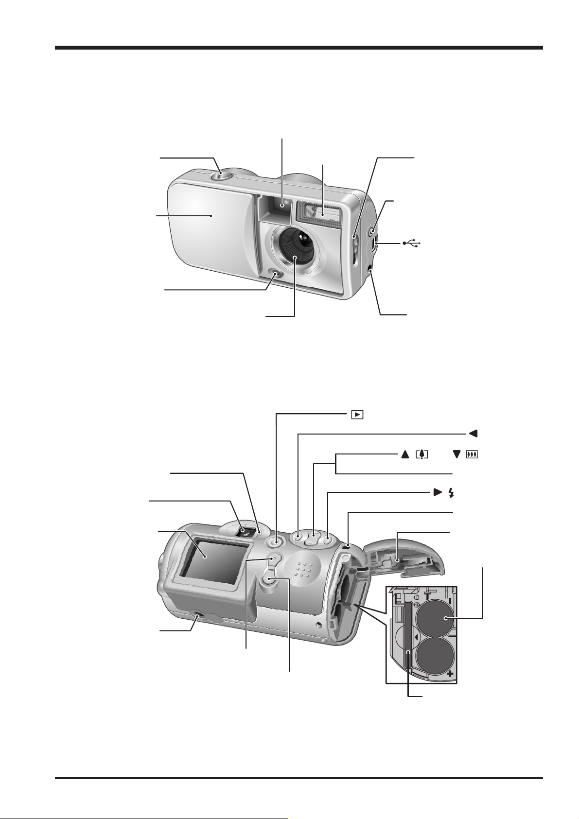
1-3.Names of External Components
Viewfinder window
1.General
Shutter button
Power switch
/ Lens cover
Self-timer lamp
Lens
Flash
Macro selector switch
VIDEO OUT (Video output)
socke
USB socket (mini-B
DC IN 3V (power input)
socket
ON (Playback) button
button
Viewfinder lamp
Viewfinder
LCD monitor
Tripod mount
MENU/OK button
DISP (Display) / BACK button
/ (Tele) / (Wide
Zoom switch
/ Flash button
Strap mount
Battery cove
compartmen
xD-Picture Card slot
Batter
7

1.General
2.Disassembly
2-1.Name of Internal Parts
BAT HOLDER
ENGN PWB ASSY
Fine Pix A120 SERVICE MANUAL
CABI REAR DECO
CABI REAR
LENS UNIT
LCD ASSY
MAIN PWB ASSY
RELEASE BUTTON
MAIN FRAME
CABI FRONT
BARIA ASSY
DECORATION
8

Fine Pix A120 SERVICE MANUAL
2-2.How to Disassemble the CABI REAR ASSY.
(1)Open the BATTERY COVER in the direction of the
arrow.
(2)Remove the 5special shape screws.(3ULR 1.7X3.5)
*Because the screws are special shape,use the exclu-
sive use jig driver(ZJ00538-100)
2
(3)Remove the CABI REAR ASSY in the direction of the
arrow.
2.Disassembly
3
1
2-3.How to Disassemble the BATERY HOLDER.
(1)Remove the 2 screws.
(2)Remove the BA TER Y HOLDER in the direction of the
arrow.
1
1
2
9
2.Disassembly
Fine Pix A120 SERVICE MANUAL
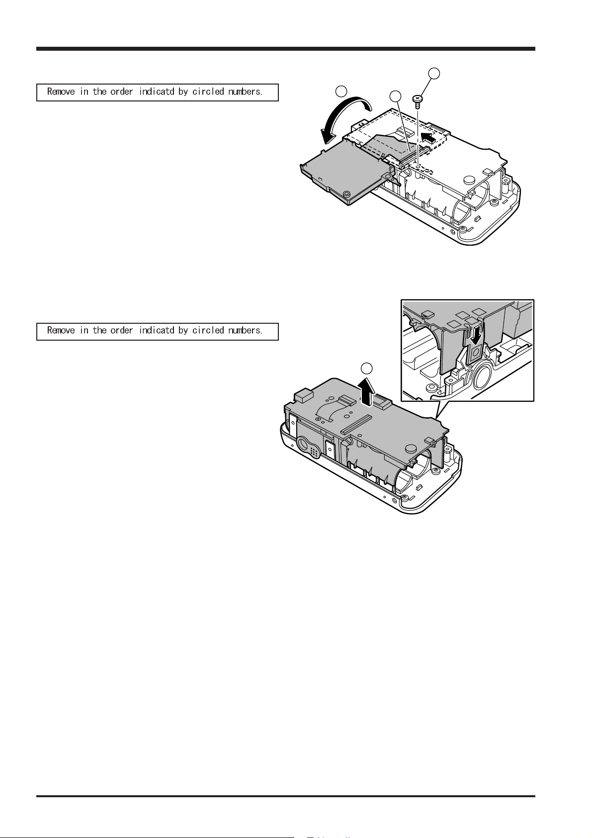
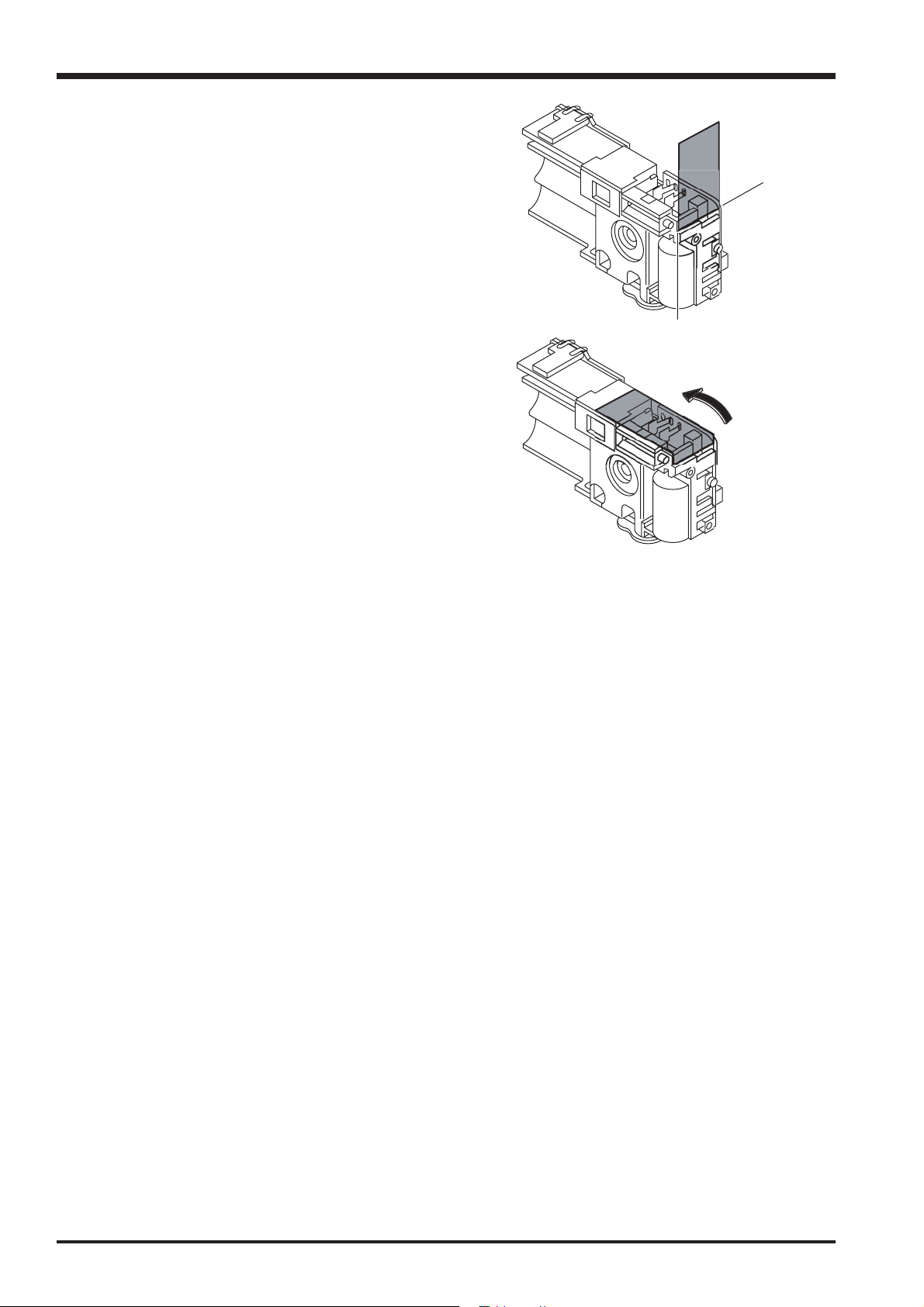
2-4.How to Disassemble the LCD UNIT.
(1)Remove the 1 screws.
Remove the SHEET MAIN in the direction of the arrow.
(2)Raise the LCD UNIT in the direction of the arrow .
(3)Remove the FPC(LCD UNIT) in the direction of the
arrow.
(MAIN PWB CN770)
2-5.How to Disassemble the INNER BLOCK.
1
2
3
(1)Remove the INNER BLOCK in the direction of the arrow.
1
10
Fine Pix A120 SERVICE MANUAL
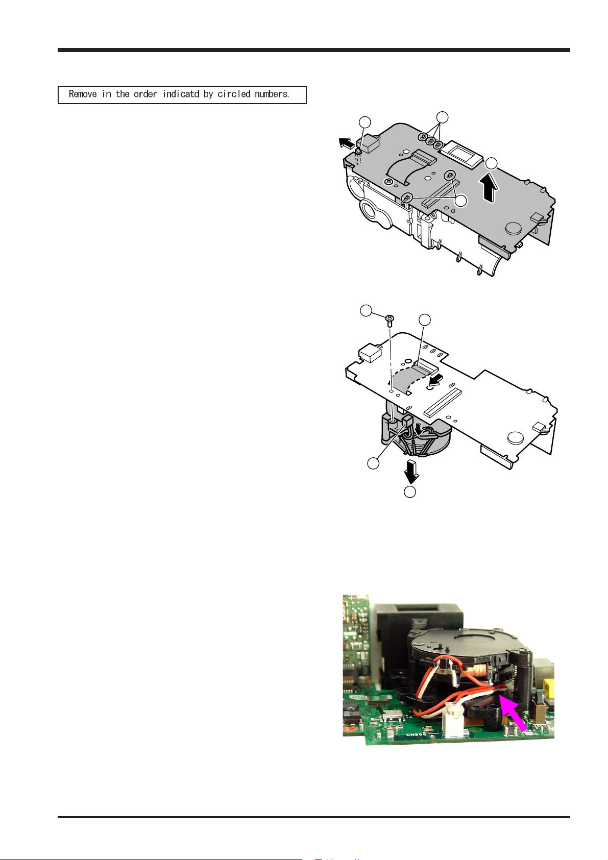
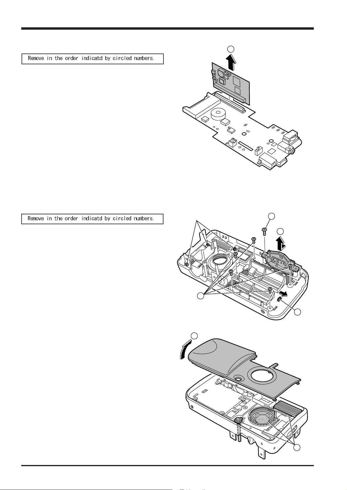
2-6.How to Disassemble the MAIN PWB.
2.Disassembly
(1)Remove the soldering(3point) of MAIN PWB ASSY.
(2)Remove the soldering(2point) of MAIN PWB ASSY.
(3)Remove the hook of MAIN FRAME(1 place).
(4)Remove the MAIN PWB(with LENS ASSY) in the di-
rection the arrow.
(5)Remove the 1 screws.
(LENS UNIT)
(6)Remove the FPC(CCD FPC) in the direction of the
arrow.
(MAIN PWB CN700)
3
5
1
4
2
6
(7)Remove the WIER HERNES(LENS ASSY) in the di-
rection the arrow.
(MAIN PWB CN900)
(8)Remove the LENS ASSY in the direction the arrow.
[Note]
Make the WIER HERNES a style like a right photo-
graph when assembling it.
7
8
11
2.Disassembly
2-7.How to Disassemble the ENGIN PWB.
(1)Remove the ENGIN PWB in the direction of the ar-
row.
(MAIN PWB CN901)
[Note]
Set the connector side of engine PWB on the CN801
side of MAINPWB.
Do not insert it diagonally when you assemble it.
Fine Pix A120 SERVICE MANUAL
1
2-8.How to Disassemble the CABI FRONT.
(1)Remove the 1 screws.
(2)Open the RELEASE BUTTON in the direction of the
arrow.
(3)Remove the 5 screws.
(4)Remove the hook of DECORATION PANEL(1 place)
in the direction of the arrow.
[Note]
Do not damage the hook of DECORATION PANEL
(3 place).
(5)Remove the DECORA TION PANEL in the direction of
the arrow.
Hook
5
1
2
3
4
(6)Remove the STROBE COVER/LED WINDOW/LENS
COVER.
12
6
Fine Pix A120 SERVICE MANUAL
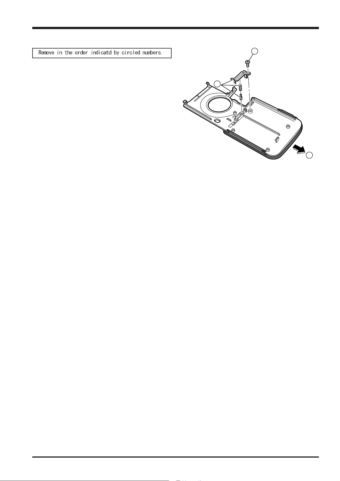
2-9.How to Disassemble of BARIA ASSY.
(1)Remove the 1 screw.
2.Disassembly
1
(2)Remove the BH PLA TE/BARRIER CLICK CSP/CLICK
SHAFT.
(3)Remove the BARIA ASSY in the direction of the
arrow.
2
3
13
2.Disassembly
S
A
2-9.Location of Sheet Parts.
[Attention when Reassemble.]
Do not use removed “Sheet Parts”.
Use surely new parts at the time of reassembly.
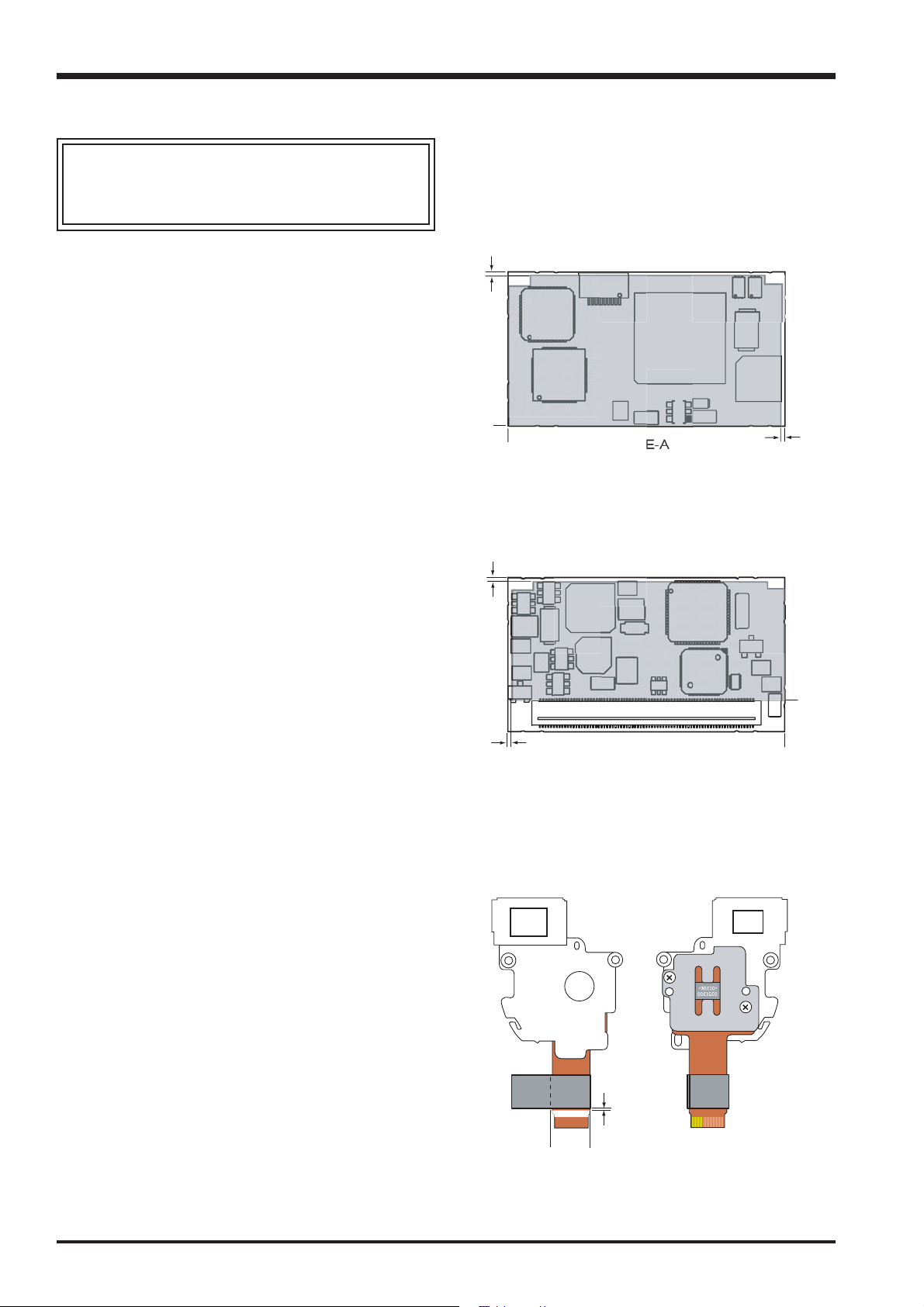
2-9-1.EMI SHEET(FZ05858-100)
Put the EMI SHEET(FZ05858-100) on side-A of
ENGINE PWB.
*The putting starting position is an edge of ENGINE
PWB(A)(B).
*Do not exceed it from the ENGINE PWB edge(C)(D).
Fine Pix A120 SERVICE MANUAL
C
A
ID
2-9-2.EMI SHEET (FZ05857-100)
Put the EMI SHEET(FZ05857-100) on side-B of
ENGINE PWB.
*The putting starting position is an edge of ENGINE
PWB(A)(B).
*Do not exceed it from the ENGINE PWB edge(C)(D).
2-9-3.EMI SHEET (FZ05856-100)
Put the EMI SEAT(FZ05856-100) on FPC of LENS
ASSY.
C
D
CN700
SIDE-B
B
*Put it based on white line edge (B) of FPC and FPC
edge (A).
And, turn by the (C) position on the other side.
B
C
A
14
Fine Pix A120 SERVICE MANUAL
A
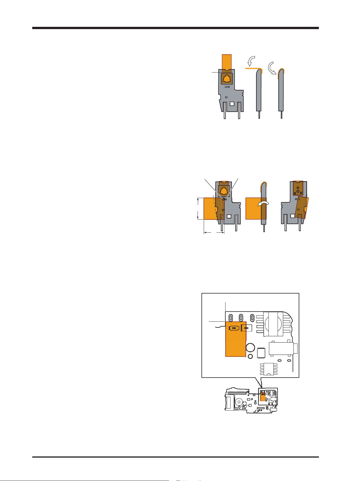
2-9-4.K TAPE 1(RELESE SWICH)
(1)Put K TAPE 1 on the SW side of RELESE SWICH.
*FZ00024-100(polyimide tape PIT- 652S) is cut in
5X10mm and it uses it.
*Put it so as not to run aground in K-TAPE on the
surface of SW(A).
(2)Turn K TAPE 1, and put on the back side of RELESE
SWICH.(B)(C)
2-9-5.K TAPE 2(RELESE SWICH)
2.Disassembly
(1)Put K TAPE 2 on the SW side of RELESE SWICH.
*FZ00024-100(polyimide tape PIT- 652S) is cut in
10X9mm and it uses it.
*Put it so as not to close hole (B).
(2)Turn K TAPE 2 along line (C), and put on the back
side of RELESE SWICH.
2-9-6.K TAPE 3(MAIN PWB)
Put the K TAPE 3 on side-A of MAIN PWB.
*FZ00024-100(polyimide tape PIT- 652S) is cut in
9X15mm and it uses it.
10mm
A
B
mm
A
B
*The putting starting position is an edge of MAIN
PWB(A)(B).
15
2.Disassembly
A
2-9-7.UL TAPE 1(MAIN FRAME)
(1)Put UL T APE 1 according to the dif ference part of MAIN
FRAME.(A)(B)
(2)Fold in direction of the arrow (C), and put it on an op-
tical finder.
*FS00099-100(UL Tape,19mm*0.23mm) is cut in
40X19mm and it uses it.
Fine Pix A120 SERVICE MANUAL
B
16

Fine Pix A120 SERVICE MANUAL
3.Schematics
3.Circuit Diagrams
3-1.Cautions
Precautions in parts replacement
Do not reuse detached electronic components. Use only new components.
The negative side of tantalum capacitors is weak against heat. Handle with care.
With the exception of Chemical capacitor and tantalum capacitors, the voltage of capacitors of a 50V or lower withstand
voltage is not labeled.
Unless specified, electronic component resistance is 1/16W.
K = 1000 , M = 1000 K
3-2.Names and Functions of Basic Blocks
Board Name Block name Function
LENS ASSY CCD BLOCK CCD output (IC1)
MAIN PWB MAIN BLOCK Shutter drive (IC900)
ENGINE PWB ENGINE BLOCK A/D conversion of CCD output (IC171), CCD driver (IC172),
TG control (IC173), Flash Rom (IC204),
Image signal processing, system control, USB, LCD drive, DRAM (IC202),
Clock generator (IC203), VIDEO driver (IC206)
Power supply generation for loads, Flash control (IC301)
Operating switches ( U<->D / L<->R / OK<->CANCEL / CAM<->PB)
LCD CONST LCD display
17

3.Schematics
Fine Pix A120 SERVICE MANUAL
3-3.Functions of Primary Blocks
3-3-1.Technical Outline
1/2.7 -inch CCD of 3.1 million pixels(total).
An [xD picture card] is adopted as the recording media. ICs are the [AFE (IC171)] for CCD processing, [HPS IC
(IC301)] that incorporates power supply management capabilities into operation system processing, and system LSI
[XCS2 (IC202)] that pakeged signal processing, LCD drive, V-TG functions.
Video-out (NTSC/PAL) is added.
3-3-2.MAIN Board Block Functions
Photography Circuit Functions (MAIN BLOCK)
The analog video signal output from the CCD (1/2.7”, 3.1 million effective pixels,) is processed (pseudo-color
compensation, adaptive interpolation, amplification, and signal mixing) in AFE_IC (ENGINE PWB: IC171:CSP_IC),
and subsequently converted to a 12-bit digital signal. The digital signal is then sent to the single chip image signal
processing LSI : XCS2_IC (IC202 : CSP_IC*).
* CSP_IC=Chip Size Packege IC
3-3-3.ENGINE Board Block Functions
Image Signal Processing Functions (ENGINE BLOCK)
Data input from CCD
* The analog signals output by the CCD (1/2.7 CCD of 3.1 million pixels[total] [IC1]) undergo color compensation,
adaptive interpolation, amplification (ACG) and signal mixing in the [AFE(IC171)] CCD signal processing IC. After
that, the signals are converted into 12-bit digital signals and sent to the [XCS2_IC (IC202)] system LSI. This block
has a vertical drive IC (IC172) for driving the CCD.
* At the same time, AE multiplies the 12-bit image data input from the XCS2_IC in [AUTO], and sends the data re-
quired for AE/AWB/AF to the SDRAM_area. To provide the appropriate data for AE/AWB/AF, this data is then sent
from the SDRAM_area in serial format to the AFE_IC via the XCS2_IC.
Recording in the xD media
The image data stored in the SDRAM_area is converted from 16-bit to 12-bit data one line at a time in the [IBUF] in the
XCS2_IC, and sent to [YC PRO]. The image data is then converted to 8-bit Y and C signals in [YC PRO], and then sent
again to [IBFC]. The 8-bit Y and C signals are then converted to 8-bit Y, Y, Cb, and Cr signals and sent to the
SDRAM_area. The image data stored in the SDRAM_area is compressed with [JPEG] in the XCS2_IC and again
stored in the SDRAM_area. The image data following compression is recorded sequentially in the xD media in the
XCS2_IC.
Image Replay from the xD media
The compressed image data from the xD media is sent to XCS2_IC, and stored in the SDRAM_area via [MEDIA].
The compressed image data stored in the SDRAM_area is expanded with JPEG and stored again in the
SDRAM_area. The expanded image data is sent to [YC PRO] via [IBFC]. Gain control for the luminance and color
difference signals, and aperture processing, are performed in [YC PRO] and the image data then sent again to the
SDRAM_area. The image data is then displayed via [ENCD] and [D/A].
The photography adjustment data is stored in the FLASH_ROM (In the IC204). The FLASH_ROM also incorporates
firmware.
LCD Control Functions
The R, G, and B signals processed in the image signal processing XCS2_IC are output to the LCD panel via [LCD CONT].
A low-temperature polysilicon TFT color LCD monitor (62,000 pixels) is used.
Power Supply Functions
The power supply on the ENGINE board and MAIN board generates the -7.5V/15V (CCD), 1.5V (XCS2_IC), 3.3V
(AFE_IC/XCS2_IC/F_ROM/LED/KEY), MOT_5.0V (lens/flash), D_5V (AUDIO), LCD_13V (LCD backlight), D_3.3V
(LCD), and AD_3.3V (Video/ LCD) voltages.
18
Fine Pix A120 SERVICE MANUAL
3.Schematics
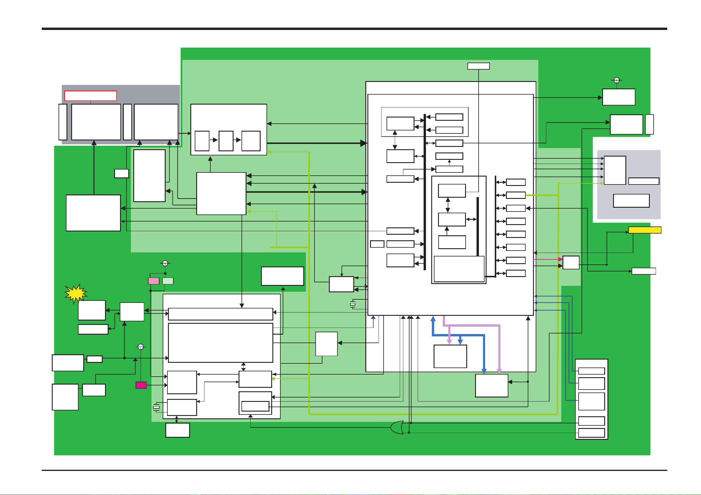
3-4.Block Diagram
FinePix A120 Block Diagram
OPTICAL FINDER
PAN FOCUS
LENS
LENS Barrier
DC IN JACK
3.3V
BATT
AAx2
Cont.
Pulses
Motor Drv
TK10201AM
2ch
IC900
STRB_XE
STRB C
FUSE
Thermal
Protector
O.LPS
OFD
STROBO
Block
STRB_UNREG
SELF TIMER,BATT CHG
CCD
1/2.7inch
3.1million pixels
V Drv
MD2174
IC172
SHT PULSE
MTR_ON
OFD_V CONT
D3.3V
LED LED
D3.3V
LED
X’TAL
FC 255
32.768kHz
BATT
Backup
ENGINE PWB
RENESAS AFE
HD49340NP
3.3V Operation
CCDIN
CDS A/D C
V
H
RTG
FF1170
3.3V Operation
(Programmable)
V Pulses
LED
DRIVER
3
RTC
PGA
HPS
AN30202
STROBOCTRL
DC/DC Block
D_3.3V
16V,-8V
DC_3.3V
SYS_3.3V
IC173
IC171
VRESET,OCONT
VI,HI,ADCK
TG_CS
CAM_SIO
STRB_SY
CTL
Power on
Reset
IC301
AFE_CS
CCD[9-0]
CAM_SIO
CCDCLK
5V
AD_3.3V
TRB CHG
BATT_V
HPS_CS
PWSW
RESET
FCS_VCONT
VCLK_ON,CCD27_ON
27MHz
CLOCK
Generator
X’TAL
CX 53F
48.00MHz
CCD
Voltage
CCD_VH(L)_SEL
Select
PWON ACT
24MHz
48MHz
XCS2 SIP
IBFC
RECC
YCPRO
CGEN
EVR
Audio(A/D)
A/D
JPEG
NTSC/PAL_SEL
24.545/24.375MHz
XCS2
MEDIA
DEBUG I/F
CPU Core
I-cache 4k
BUS COT.
SDRAM
DRAM
(MAX 48MHz)
SDRAM
128MB x16
JTAG
3.3V Operation
AUTO
CCDIF
TFDC
ENCD
ADDRESS BUS [11-30]
DATA BUS [0-15]
NOR FLASH
2MB
IC204
LCD EVR
IC202
WDT
SIO
USB
MFT
ICU
ADC
PORT
CLKC
BEEP1,2
LCDDAT[7:0]
BL ON,LCD ON
LCDHD,LCD_VD,LCDCLK
LCD_CS
Vbus,D+,D-
AV_DET
VBS_OUT
VIDEO ON
X2_SIO
Video
Driver
IC601
RLDU
MODE
KEY4
USER I/F
RLDU SW
MODE
SW
OK/BACK
(DISP)
SW
CAM/PB
PWR SW
D_3.3V
BUZZER
LCD
Cont.IC
xD CARD
Slot
(20PIN)
LCD Panel
1.5inch
BL LED x2
DCDC
From DCDC
D_3.3V
VIDEO JACK
USB I/F
DR_SW
MAIN PWB
19
3.Schematics
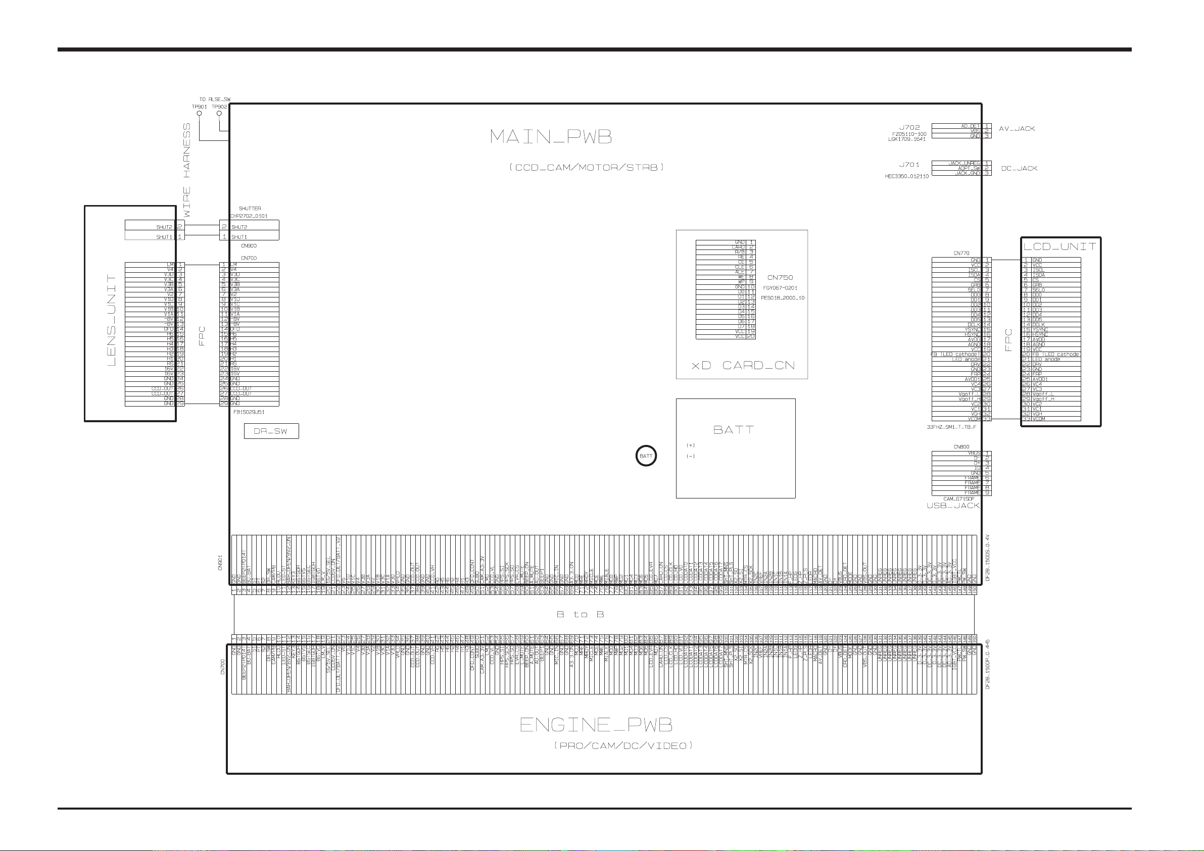
3-5.Overall
Fine Pix A120 SERVICE MANUAL
20
 Loading...