

FUJIFILM FinePix 30I SERVICE MANUAL
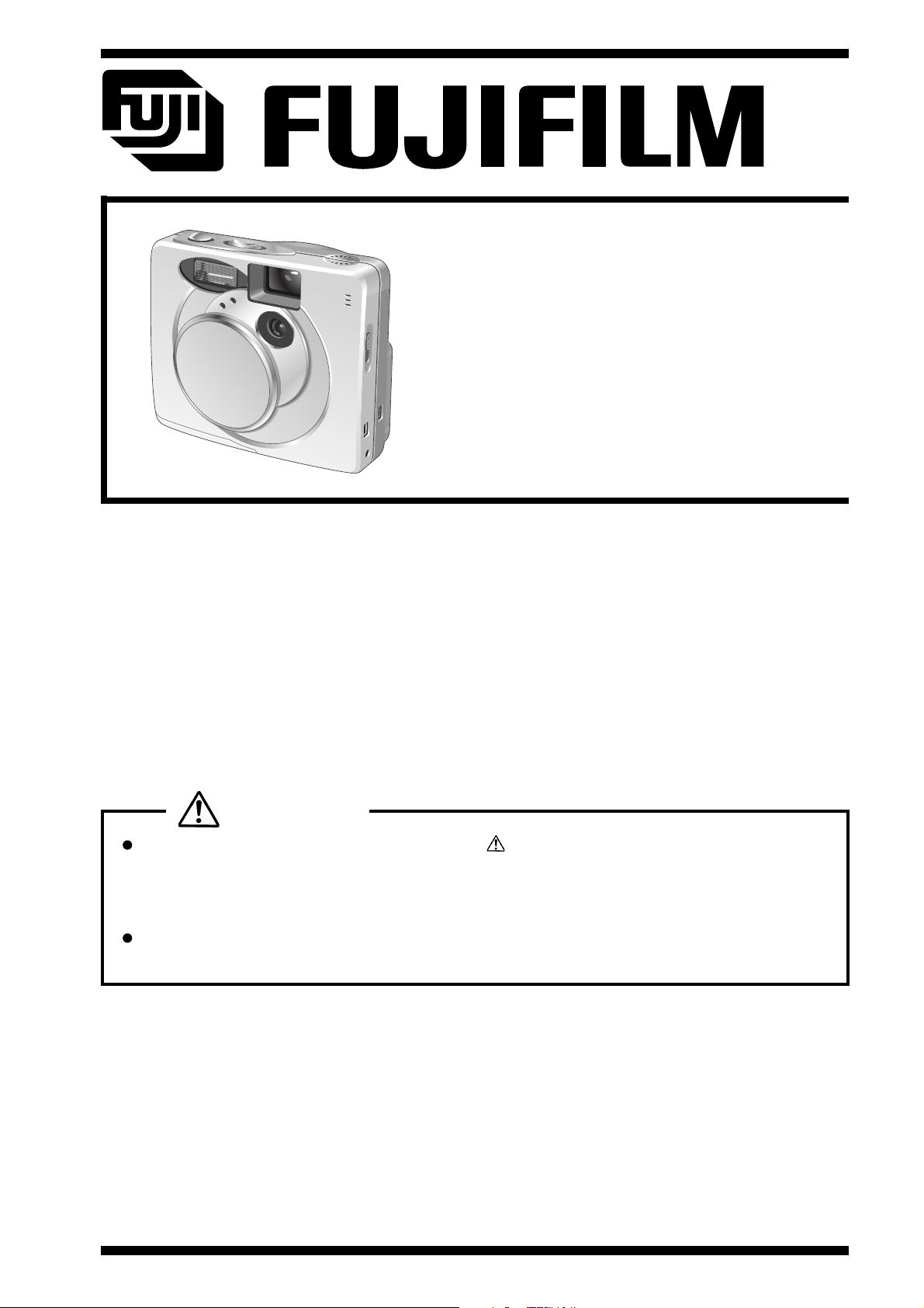
DIGITAL CAMERA
FinePix30i
SERVICE MANUAL
U/E/EG_Model
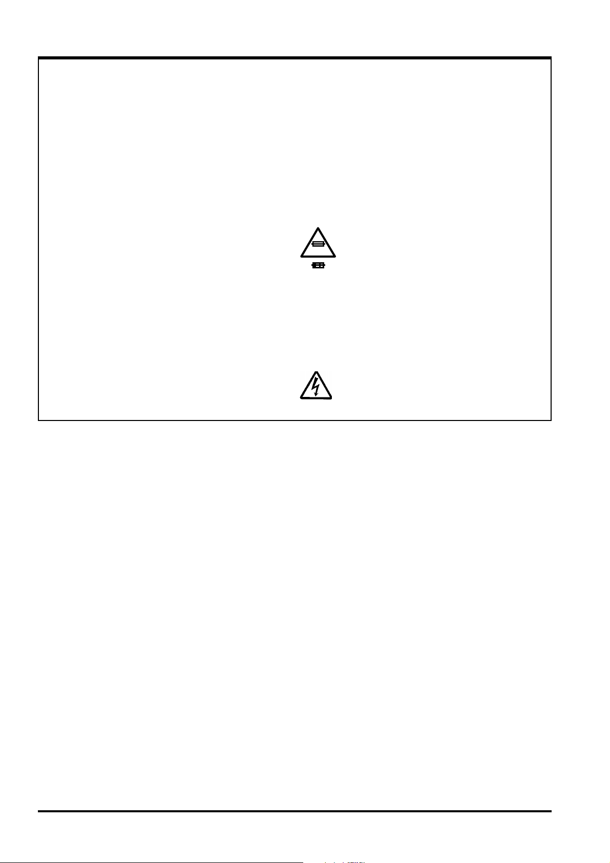
WARNING
THE COMPONENTS INDENTIFIED BY THE MARK ON THE SCHEMATHIC DIAGRAM AND
IN THE PARTS LIST ARE CRITICAL FOR SAFETY.
PLEASE REPLACE ONLY BY THE COMPORNENTS SPECIFIED ON THE SCHEMATHIC DIAGRAM
AND IN THE PARTS LIST.
IF YOU USE WITH PART NUMBER UN-SPECIFIED, IT MAY RESULT IN A FIRE AND AN
ELECTORICAL SHOCK.
FUJI PHOTO FILM CO.,LTD.
Printed in Japan 2001.10 (M.A)
Ref.No.: ZM00414-100
SAFETY CHECK-OUT
After correcting the original problem, perform the following safety
check before return the product to the costomer.
FinePix30i SERVICE MANUAL
1. Check the area of your repair for unsoldered or
poorly soldered connections. Check the entire
board surface for solder splasher and bridges.
2. Check the interboard wiring to ensure that no
wires are “pinched” or contact high-wattage
resistors.
3. Look for unauthorized replacement parts,
particularly transistors, that were installed
during a previous repair. Point them out to the
customer and recommend their replacement.
4. Look for parts which, though functioning, show
obvious signs of deterioration. Point them out
to the customer and recommend their
replacement.
5. Check the B + voltage to see it is at the values
specified.
6. Make leakage - current measurements to
determine that exposed parts are acceptably
insulated from the supply circuit before returning
the product to the customer.
7. CAUTION: FOR CONTINUED
PROTECTION AGAINST FIRE
2.5A125V
2.5A125V
RISK OF FIREREPLACE FUSE
AS MARKED
HAZARD, REPLACE ONLY WITH
SAME TYPE 2.5 AMPERES 125V
FUSE.
ATTENTION: AFIN D'ASSURER
UNE PROTECTION PERMANENTE
CONTRE LES RISQUES
D'INCENDIE, REMPLACER
UNIQUEMENT PAR UN FUSIBLE
DE MEME, TYPE 2.5 AMPERES,
125 VOLTS.
8. WARNING:
WARNING!
HIGH VOLTAGE
TO REDUCE THE ELECTRIC
SHOCK, BE CAREFUL TO TOUCH
THE PARTS.
2

FinePix30i SERVICE MANUAL
TABLE OF CONTENTS
1.General
1-1.Product Specifications ................................................... 4
1-2.Names of External Components ..................................7
2.Disassembly
2-1.Names of Internal Components....................................8
2-2.Removing R CABI ASSY ............................................... 9
2-3.Removing LCD ................................................................ 9
2-4.Removing LENS ASSY ............................................... 10
2-5.Removing BL PWB ASSY .......................................... 10
2-6.Removing F CABI ASSY ............................................ 11
2-7.Removing CABI BOTTOM ASSY .............................. 11
2-8.Removing TOP PANEL ASSY/RSW PWB ASSY ... 12
2-9.Removing MAIN PWB ASSY ..................................... 13
2-10.Removing DCST PWB ASSY .................................. 13
2-11.Removing KEY PWB ASSY ..................................... 14
3.Schematics
3-1.Note on schematics .................................................... 15
3-2.Overview of Function of Each Circuit ....................... 15
3-3.Block Functions
3-3-1.Overview of New Technology ............................. 16
3-3-2.Description of the Block Functions
in the MAIN PWB ASSY ................ 16
3-3-3.Description of the Functions
of the DCST PWB ASSY ................ 16
3-4.Block Diagram.............................................................. 17
3-5.Overall Connections .................................................... 18
3-6.MAIN PWB ASSY Component Location .................. 1 9
3-7.DCST PWB ASSY Component Location .................. 20
3-8.CCD PWB ASSY Component Location .................... 21
3-9.KEY PWB ASSY Component Location .................... 22
3-10.LCDF PWB ASSY Component Location ................ 23
3-11.RSW PWB ASSY Component Location ................. 24
3-12.BL PWB ASSY Component Location ..................... 25
4.Adjustment
4-1.Important Point of Adjustments
when Replacing Major Parts ....................................... 26
4-2.Preparation for adjustments
4-2-1.Measuring Instrument Used ............................... 26
4-2-2.List of Jigs Used .................................................. 26
4-2-3.Jigs connection diagram ..................................... 27
4-2-4.Environmental setting for adjustment ............... 27
4-3.Adjusting by PC
4-3-1.Various downloading software
decompressions, preservation
methods, and note ................................................. 28
4-3-2.Content of adjustment software ......................... 29
4-3-3.Start of adjustment software .............................. 29
4-3-4.Initialization of adjustment software.................. 29
4-3-5.Command descriptions for[FFW.exe] ............... 31
4-4.Adjustment of each part(For PC adjustment)
4-4-1.Start of program ................................................... 32
4-4-2.Initiation method in JIG mode of camera ......... 32
4-4-3.Battery adjustment ............................................... 3 3
4-4-4.LCD adjustment .................................................... 33
4-4-5.CCD data input ..................................................... 34
4-4-6.CAM adjustment ................................................... 34
4-4-7.Flash adjustment .................................................. 36
4-4-8.End setting ............................................................ 37
Page
TABLE OF CONTENTS
Page
5.Check
5-1.Check ........................................................................... 38
6.Parts List
6-1.Packing and Accessories
6-1-1.U_MODEL ............................................................. 39
6-1-2.E_MODEL.............................................................. 40
6-1-3.EG_MODEL ........................................................... 41
6-2.Mechanical Parts
6-2-1.F CABI ................................................................... 42
6-2-2.R CABI ................................................................... 43
6-3.Electrical Parts ............................................................ 44
7.Troubleshooting
7-1.Troubleshooting ....................................................... 46
8.Appendix
8-1.List of Related Technical Updates Issued ........... 47
3
1.General
FinePix30i (U/E/EG) SERVICE MANUAL
1-1Product Specifications
System
Model Digital camera FinePix30i
Number of effective pixels Approx. 2.0 million pixels
CCD sensor 1/2.7-inch square pixel CCD with RGB color filter
(Number of total pixels: 2.11 million pixels)
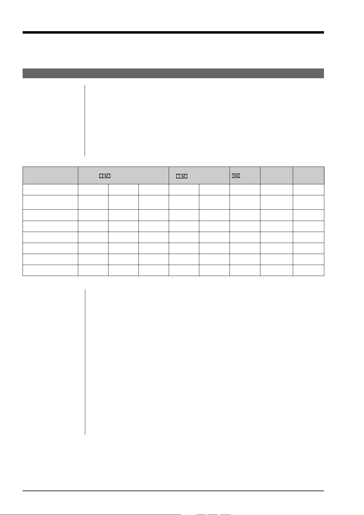
Number of recorded pixels 1600 x 1200 pixels/1280 x 960 pixels/640 x 480 pixels
File format Still image: Design rule for Camera File System compliant (Exif Ver.2.1 JPEG), DPOF compatible
Movie: AVI format, Motion JPEG
Audio: WAV format Exif Ver. 2.1 audio file standard-compliant
Storage media SmartMedia (3.3V)
Standard number of shots per SmartMedia
File Size 1600 x 1200 1280 x 960
Quality Mode FINE
Image Data Size
Approx. Approx. Approx. Approx. Approx. Approx.
770KB 390KB 200KB 620KB 320KB 130KB
NORMAL
BASIC FINE
NORMAL NORMAL
MG-4S (4MB) 4 9 19 6 12 30
MG-8S (8MB) 10 19 39 12 25 61
MG-16S/SW (16MB)
MG-32S/SW (32MB)
MG-64S/SW (64MB)
MG-128SW (128MB)
20 39 75 25 49 122
41 79 152 50 99 247
82 159 306 101 198 497
166 319 613 204 398 997
640 x 480
Movie Audio
(Video) recording
--
--
Approx. 23 sec. Approx. 8 min.
Approx. 47 sec. Approx. 16 min.
Approx. 94 sec. Approx. 33 min.
Approx. 191 sec. Approx. 67 min.
Approx. 385 sec. Approx. 135 min.
Approx. 774 sec. Approx. 272 min.
* The numbers of available shots are shown for formatted SmartMedia.
Sensitivity Equivalent to ISO 100
Lens Fujinon optical fixed-focus lens
Focus distance f = 5.8 mm (Equivalent to 38 mm on a 35 mm camera)
Viewfinder Inverted Galiean finder
Exposure control TTL 64-zones metering, Program AE, exposure compensation available in Manual still
image mode
White balance Auto (in Manual modes, 7 positions can be selected)
Focal range Normal: Approx. 60 cm (2.0 ft.) to infinity
Macro: Approx. 8 cm to 15 cm (0.3 ft. to 0.5 ft.)
Shutter Variable-speed, 1/2 sec. to 1/1000 sec. (using AE)
Aperture F4.8 or F11 (automatically selected)
Self-Timer 10 sec. timer clock
Erase modes ERASE FRAME, ERASE ALL FRAMES, MUSIC TRACK, ALL MUSIC TRACKS, FORMAT
(initialize)
LCD monitor 1.8-inches, 72,000 pixels D-TFD
Flash Auto flash using flash control sensor
Effective range: Approx. 0.6 m to 3 m (2.3 ft. to 9.8 ft.)
Flash modes: Auto, Red-Eye Reduction, Forced Flash, Suppressed Flash, Slow Synchro
4
FinePix30i (U/E/EG) SERVICE MANUAL
1.General
Music
Recording media SmartMedia with ID (3.3 V)
Playback system MP3
Encryption method InfoBind
Continuous playback time Approx. 4 hours 30 minutes (using the batteries provided when fully charged)
Bass boost 2 levels
Playback modes NORMAL, REPEAT ALL TRACKS, REPEAT TRACK
Output 5 mW x 2
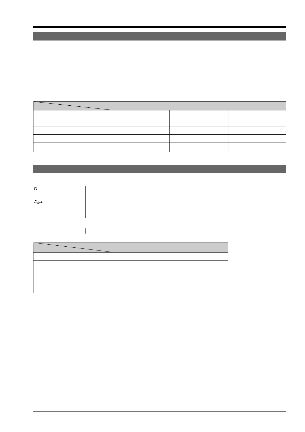
Standard recording times for SmartMedia with ID
Bit rate
SmartMedia 128kbps 112kbps 96kbps
MG-16SW (16MB) Approx. 15 min. Approx. 18 min. Approx. 20 min.
MG-32SW (32MB) Approx. 30 min. Approx. 35 min. Approx. 40 min.
MG-64SW (64MB) Approx. 60 min. Approx. 70 min. Approx. 80 min.
MG-128SW (128MB) Approx. 120 min. Approx. 140 min. Approx.160 min.
* The recording times shown are for a formatted SmartMedia.
Input/Output Terminals
<Camera>
REMOTE Special remote controller jack
(remote controller) socket
(USB) socket USB (1) for image data output with a personal computer
DC IN 3V (Power input) Socket for specified AC power adapter
socket
<Remote controller>
Headphone socket Stereo, mini-jack (3.5 mm dia.)
Audio Output
Headphone Speaker
MP3 Yes No
Movie (Audio) No Yes
Voice captioning No Yes
Audio recording Yes Yes *
BEEP No Yes
*No audio output when the remote controller connection is used.
5

1.General
FinePix30i (U/E/EG) SERVICE MANUAL
Power supply and Others
Power supply Use one of the following
* 2AA-size Ni-MH (nickel-metal hydride) batteries (included)
* AC-3V Power Adapter (sold separately)
Available shots/time using the battery (using the batteries provided when fully charged)
Battery Type No. of Shots
LCD monitor ON Approx. 120 Approx. 80 min. Approx. 80 min.
LCD monitor OFF Approx. 300 Approx. 240 min. ----
The number of shots shown here is an approximate guide to the number of consecutive shots that can be taken
based on 50% flash usage at normal temperatures. However, the actual number of available shots will vary de-
pending on the ambient temperature when the camera is used and the amount of charge in the batteries.
o
Conditions for use Temperature: 0
80% humidity or less (no condensation)
Camera dimensions 84.7 mm x 72.5 mm x 29.5 mm/3.3 in. x 2.9 in. x 1.2 in.
(W/H/D) (not including accessories and attachments)
Camera mass (weight) Approx. 150 g/5.3 oz. (not including accessories, batteries or SmartMedia)
Mass (weight) Approx. 205 g/7.2 oz.
for photography (including batteries and SmartMedia)
Accessories AA-size Nickel-Metal Hydride (Ni-MH) Batteries HR-3UF (2)
Shoulder Strap (1)
Remote Controller (1)
Headphones (1)
Battery Charger BC-NHS (1)
USB Interface Set (1) * CD-ROM: Software for FinePix MP (1)
Owner's Manual (1)
Optional Accessories SmartMedia MG-4S: 4MB, 3.3V MG-8S: 8MB, 3.3V MG-16S: 16MB, 3.3V
AC Power Adapter AC-3V
Fujifilm Rechargeable Battery 2HR-3UF
Fujifilm Battery Charger with Battery BK-NH (with Euro type or UK type plug)
SC-FX30 Soft Case
FD-A2 Floppy Disk Adapter (FlashPath) * Windows 95/98/98SE/Me/NT4.0
SM-R2 Image Memory Card Reader
* Compatible with Windows 98/98SE, Windows Me, Windows 2000 Professional or
iMac and models that support USB as standard.
DM-R1 Image Memory Card Reader
* Compatible with Windows 98SE, Windows 2000 Professional (read-only), iMacDV
and Power Macintosh PCs with FireWire as a standard feature. Mac OS 8.5.1 to 9.1
PC-AD3 PC Card Adapter
C to +40oC (+32oF to +104oF)
* Special USB cable with Noise Suppression core (1)
* Software Quick Start Guide (1)
MG-32S: 32MB, 3.3V MG-64S: 64MB, 3.3V
MG-16SW: 16MB, 3.3V, ID MG-32SW: 32MB, 3.3V, ID
MG-64SW: 64MB, 3.3V, ID MG-128SW: 128MB, 3.3V, ID
Audio Recording
Recording Playback
* Mac OS 7.6.1 to 9.1
6
FinePix30i (U/E/EG) SERVICE MANUAL
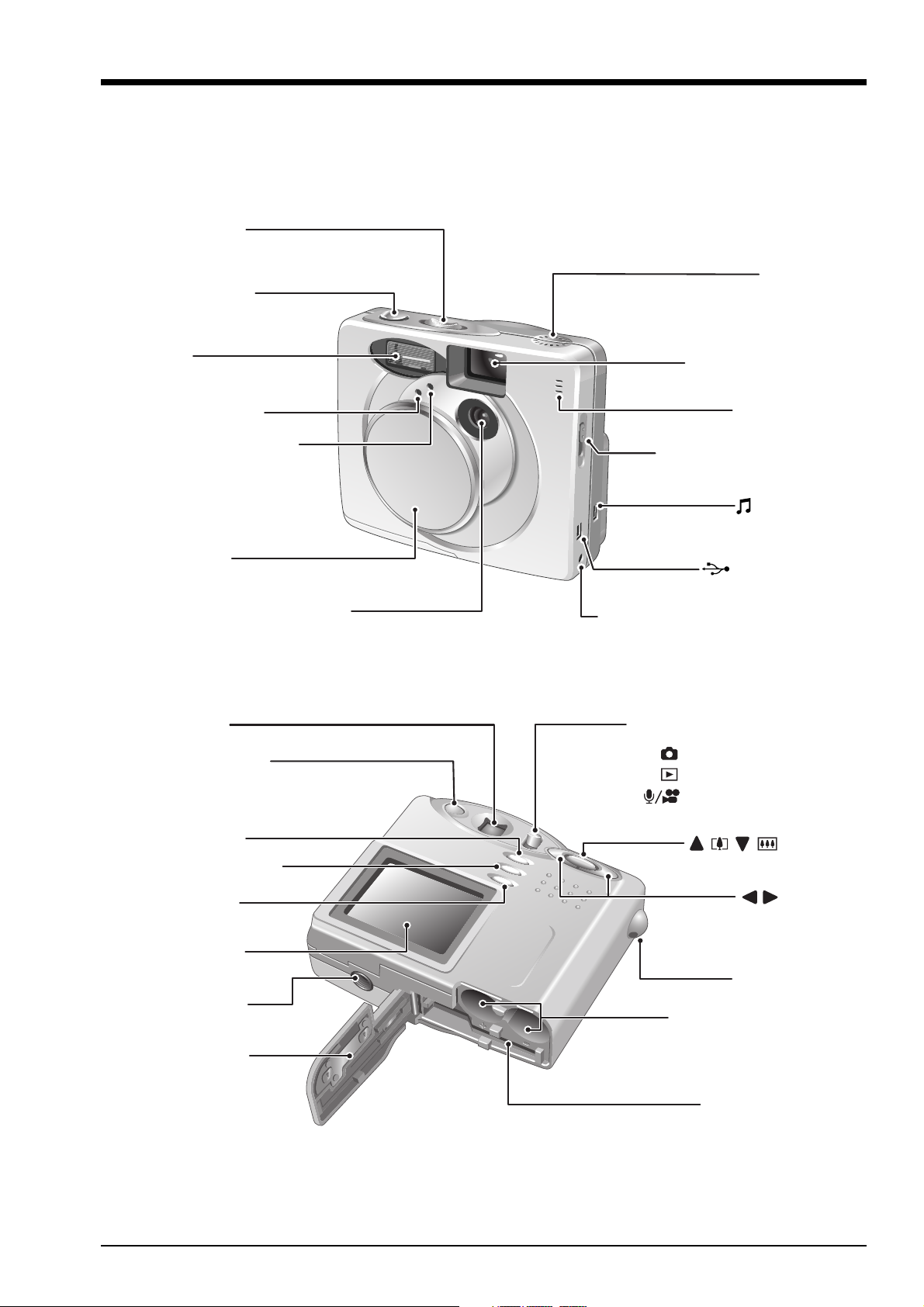
1-2.Names of External Components
Power switch
POWER
MUSIC
Shutter button
1.General
Speaker
Flash
Self-timer lamp
Flash control sensor
Lens cover
Viewfinder
Viewfinder lamp
Lens
Viewfinder window
Microphone
Macro selector switch
REMOTE
(remote controller)socket
(USB)socket
DC IN 3V(Power input) socket
Mode switch
Still image mode
Playback mode
Audio/Movie mode
BACK button
MENU/ OK button
DISP button
LCD monitor
Tripod mount
Battery cover
( )
( )
button
button
Strap mount
Battery compartment
SmartMedia slot
7
2. Disassembly
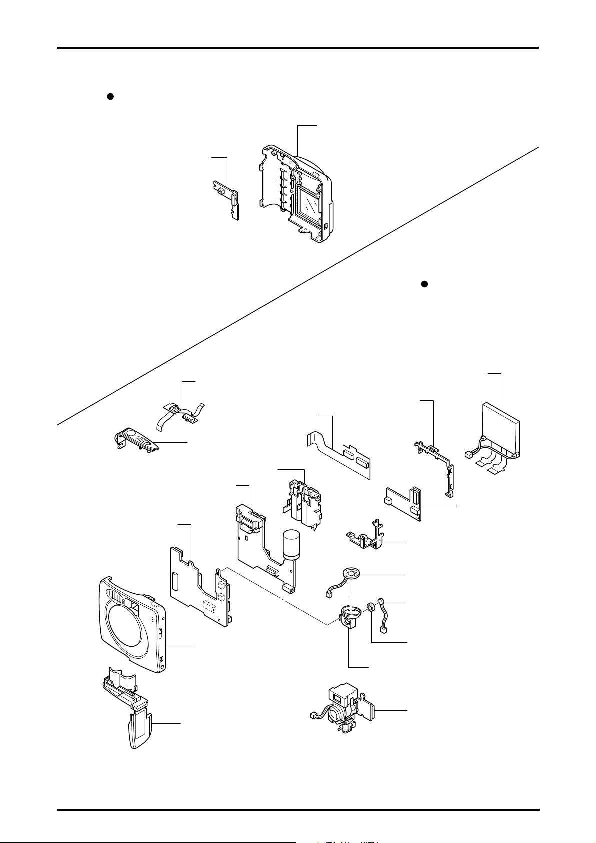
2-1.Name of Internal Components
R CABI
KSW PWB ASSY
FinePix30i(U/E/EG) SERVICE MANUAL
R CABI ASSY
F CABI
DCST PWB ASSY
MAIN PWB ASSY
RSW PWB ASSY
LCDF PWB ASSY
TOP PANEL ASSY
BATTERY HOLDER
F CABI ASSY
LCD
LCD HOLDER
BL PWB ASSY
PWB FRAME
SPEAKER ASSY
MIC ASSY
MIC GOM
MIC/SP HOLDER
LENS CONST
CABI BOTTOM ASSY
8
FinePix30i(U/E/EG) SERVICE MANUAL
2. Disassembly
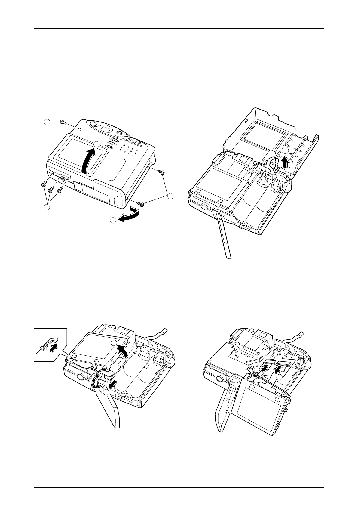
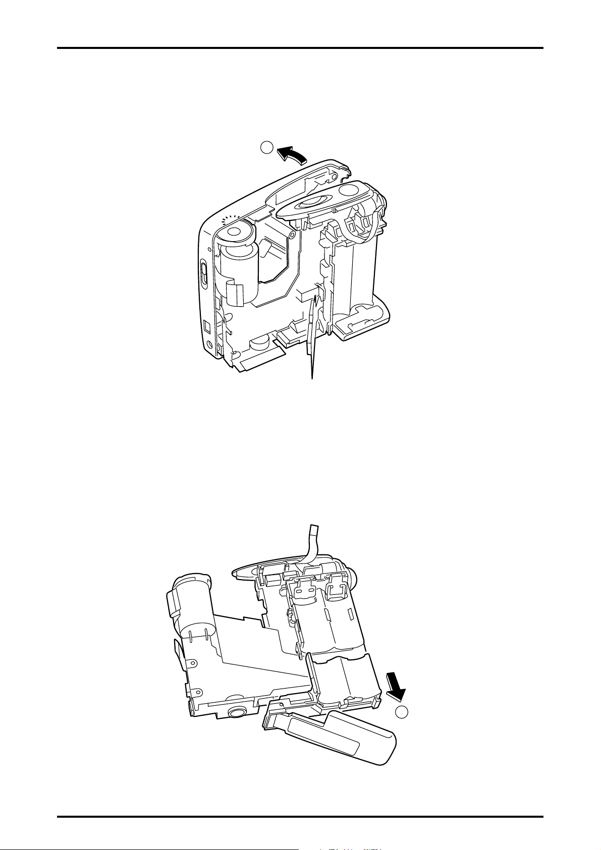
2-2.Removing R CABI ASSY
(Remove in the order indicated by circled numbers.)
[Procedure]
(1)Six screws(1.7 x 3.5 N) are removed.
(2)Open BATTERY LID
(3)R CABI ASSY is removed.
1
3
(4)FFC is removed.
1
4
1
2
2-3.Removing LCD
(Remove in the order indicated by circled numbers.
[Procedure]
(1)LCD is removed.
(2)Harness of LCD is removed.
1
(3)FFC( x 2) of LCD is removed.
3
3
2
9
2. Disassembly
2-4.Removing LENS ASSY
(Remove in the order indicated by circled numbers.)
[Procedure]
(1)FFC is removed.
(2)Harness is removed.
(3)Two screws(2 x 8) are removed.
(4)LENS ASSY is removed.
3
FinePix30i(U/E/EG) SERVICE MANUAL
1
4
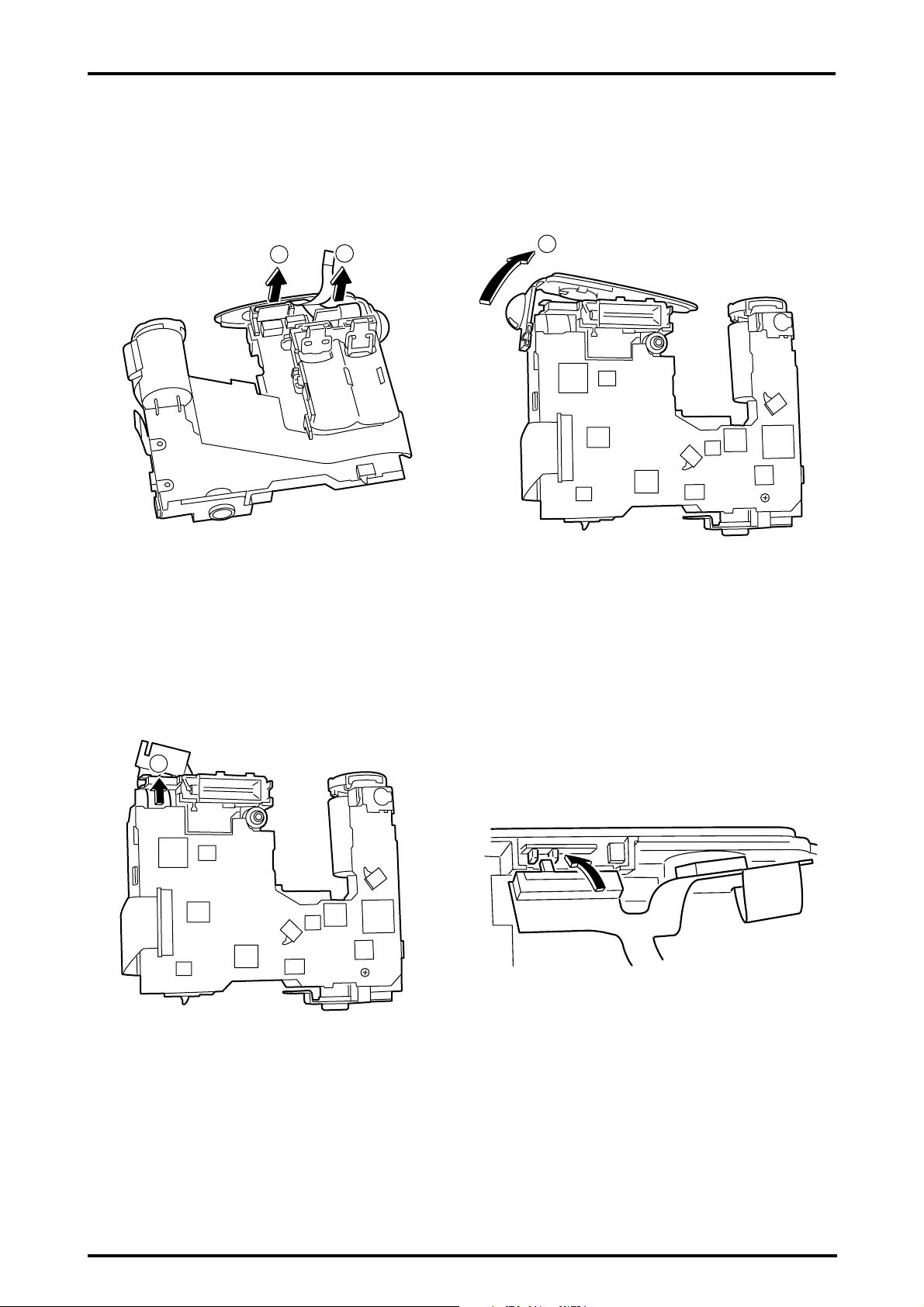
2-5.Removing BL PWB ASSY
(Remove in the order indicated by circled numbers.)
[Procedure]
2
(1)One screw(1.7 x 3.5 N) is removed.
(2)BL PWB ASSY is removed.
1
2
(3)Capacitor of the flash is discharged.
(4)FFC is removed.
3
4
10
FinePix30i(U/E/EG) SERVICE MANUAL
2-6.Removing F CABI ASSY
(Remove in the order indicated by circled numbers.)
[Procedure]
(1)F CABI ASSY is removed.
1
2. Disassembly
2-7.Removing CABI BOTTOM ASSY
(Remove in the order indicated by circled numbers.)
[Procedure]
(1)CABI BOTTOM ASSY is removed.
1
11
2. Disassembly
FinePix30i(U/E/EG) SERVICE MANUAL
2-8.Removing TOP PANEL ASSY/RSW PWB ASSY
(Remove in the order indicated by circled numbers.)
[Procedure]
(1)POWER SW part of RSW PWB ASSY is removed.
(2)RELEASE SW part of RSW PWB ASSY is removed.
1
2
(3)TOP PANEL ASSY is removed.
3
(4)FFC is removed.
4
(Attention at assembly
Please note the position of the power knob of
TOP PANEL and POWER SW of RSW PWB.
12
FinePix30i(U/E/EG) SERVICE MANUAL
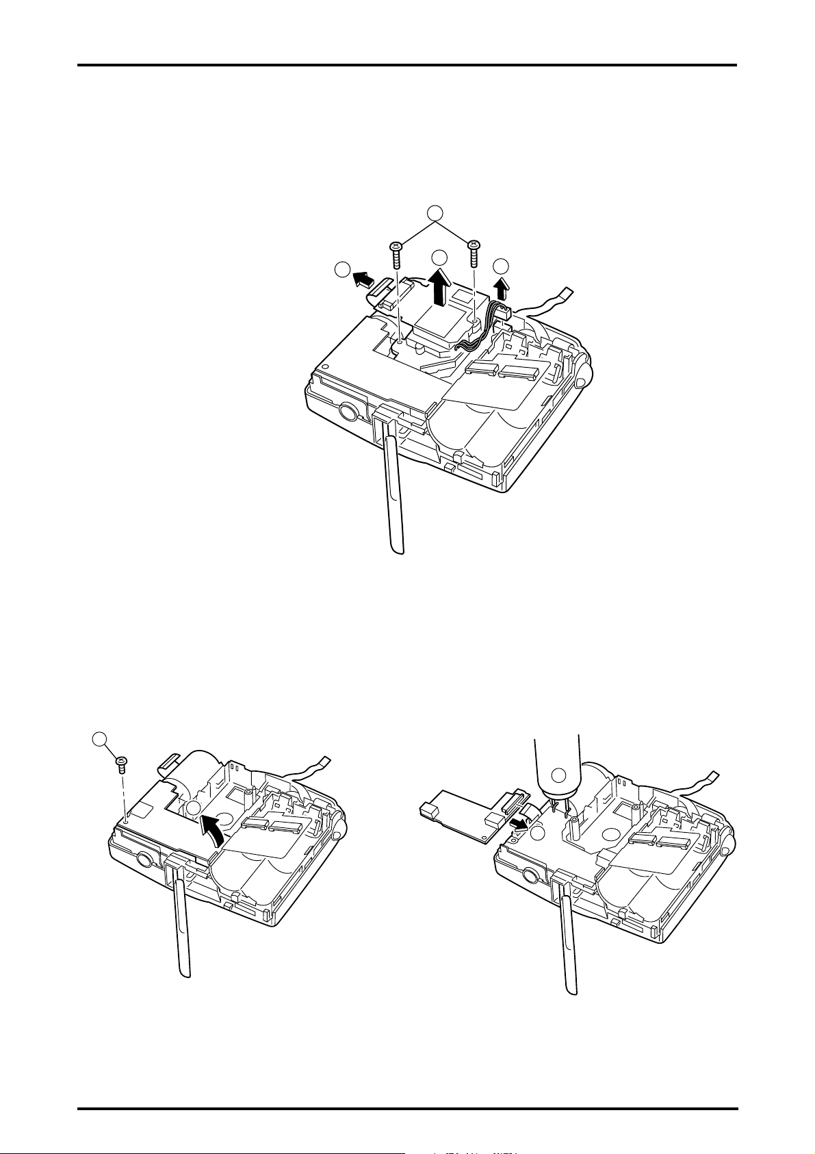
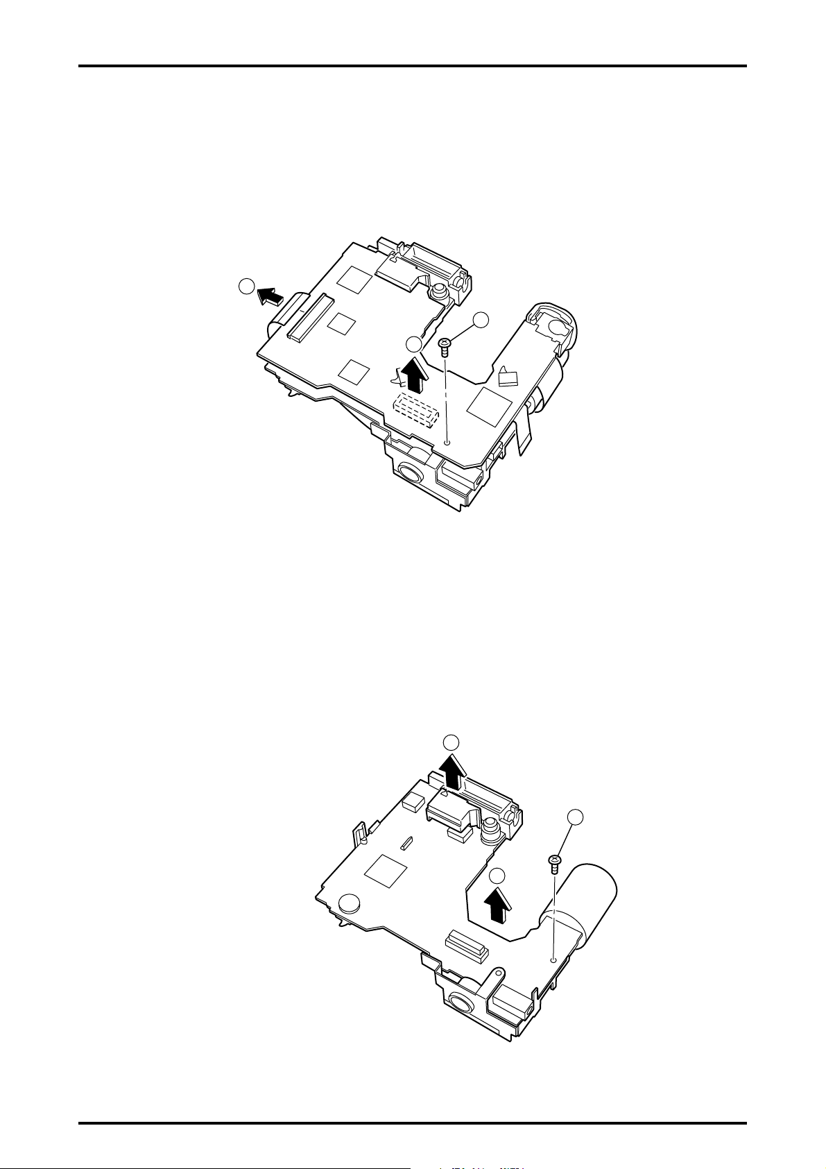
2-9.Removing MAIN PWB ASSY
(Remove in the order indicated by circled numbers.)
[Procedure]
(1)FFC is removed.
(2)One screw(1.7 x 3.5 N) is removed.
(3)MAIN PWB ASSY is removed.
1
3
2. Disassembly
2
2-10.Removing DCST PWB ASSY
(Remove in the order indicated by circled numbers.)
[Procedure]
(1)TRIGER COVER is removed.
(2)One screw(1.7 x 3.5 N) is removed.
(3)DCST PWB ASSY is removed.
1
2
3
13

2. Disassembly
2-11.Removing KEY PWB ASSY
(Remove in the order indicated by circled numbers.)
[Procedure]
(1)Two screws(1.7 x 3.0 N) are removed.
(2)KEY PWB ASSY is removed.
1
2
FinePix30i(U/E/EG) SERVICE MANUAL
(Attention at assembly
Please note the position of MODE KNOB and the position of MODE SW.
14

FinePix30i(U/E/EG) SERVUCE MANUAL
3.Schematics
3-1.Notes on Schematics
Other neccessary notes are shown in each block.
Cautions
Caution when replaceing chip (leadless) parts.
Do not re-use the removed parts, but use new parts.
Be careful that the negativ side of the tantalum capacitors are susceptible to heat.
Voltage indications are omitted for capacitors other than chemical and tantalum capacitors with a
dielectric strength of 50 V or less.All units are F (p shows pF).
Chip resistors without indication are 1/10 W.
k =1000 , M =1000k
Variable resistors and semi-variable resistor are abbreviated the specification of B characteristic.
3-2.Overview of Functions of Each Circuit.
Board Name Circuit Diagram Name Circuit Functions
MAIN Board CAM Block A/D conversion of CCD output Signal circuit
CCD Driver circuit
MOTOR Block Shutter/IRIS driving circuit
PROCESS Block System control circuit / Image signal process circuit
/USB communication circuit
AUDIO Block Voice Signal circuit
MP3 Block MP3 circuit
LCD Block Control of LCD panel
DCST Board Flash Block Flash circuit
DC/DC Block Power Supply circuit
CCD Board CCD Block CCD circuit
KEY Board KEY Block Operation SW circuit
LCDF Board LCDF Block Connect between the LCD and MAIN circuit
RSW Board SW Block Power/Release SW circuit
BL Board BACK LIGHT Block LCD Back light circuit
15
 Loading...