

FUJIFILM FinePix 2600 SERVICE GUIDE

DIGITAL CAMERA
FinePix 2600Zoom
SERVICE GUIDE
U/E/EG-Model
WARNING
THE COMPORNENTS IDENTIFIED BY THE MARK “ “ ON THE SCHEMATHIC
DIAGRAM AND IN THE PARTS LIST ARE CRITICAL FOR SAFETY.
PLEASE REPLACE ONLY BY THE COMPORNENTS SPECIFIED ON THE SCHMATHIC
DIAGRAMAND IN THE PARTS LIST.
IF YOU USE WITH PART NUMBER UN-SPECIFIED, IT MAY RESULT IN A FIRE AND AN
ELECTORICAL SHOCK.
Ref.No.:ZM00377-102
FUJI PHOTO FILM CO.,LTD.
Printed in Japan 2001.08(T.S.)

SAFETY CHECK-OUT
After correcting the original problem, perform the following safety
check before return the product to the costomer.
FinePix2600Zoom(U)Service Guide
1. Check the area of your repair for unsoldered or poorly
sol dered connections. Check the entire board sur
face for solder splasher and bridges.
2. Check the interboard wiring to ensure that no wires
are ÒpinchedÓ or contact high-wattage resistors.
3. Look for unauthorized replacement parts, particu
larly tran sistors, that were installed during a previ
ous repair. Point them out to the customer and rec
ommend their replacement.
4. Look for parts which, though functioning, show obvi
ous signs of deterioration. Point them out to the cus
tomer and recommend their replacement.
5. Check the B + voltage to see it is at the values specified.
6. Make leakage - current measurements to determine
that exposed parts are acceptably insulated from the
supply circuit before returning the product to the customer.
7. CAUTION: FOR CONTINUED
PROTECTION AGAINST FIRE
HAZARD, REPLACE ONLY WITH
SAME TYPE 2.5 AMPERES 125V
FUSE.
2.5A125V
2.5A125V
8.
RISK OF FIREREPLACE FUSE
AS MARKED
WARNING!
HIGH VOLTAGE
ATTENTION: AFIN D'ASSURER
UNE PROTECTION
PERMANENTE CONTRE LES
RISQUES D'INCENDIE,
REMPLACER UNIQUEMENT
PAR UN FUSIBLE DE MEME,
TYPE 2.5 AMPERES, 125
VOLTS.
WARNING:
TO REDUCE THE ELECTRIC
SHOCK, BE CAREFUL TO
TOUCH THE PARTS.

FinePix2600Zoom (U/E/EG) SERVICE GUIDE
TABLE OF CONTENTS
1. Specifications
1-1.Product Specifications ............................................................................................................................. 4
2. Names of Components
2-1.Names of External Components .............................................................................................................6
2-2.Names of internal Components .............................................................................................................. 7
3. Disassembly
3-1.Removing CABI R ASSY .........................................................................................................................8
3-2.Removing LCD ASSY,LCD FRAME .......................................................................................................9
3-3.Removing LENS ASSY ......................................................................................................................... 10
3-4.Removing MAIN PWB ASSY................................................................................................................ 11
3-5.Removing DCST PWB ASSY............................................................................................................... 11
3-6.Removing BATTERY HOLDER, LENS BARIA ASSY ........................................................................ 12
3-7.Removing SW PWB ASSY ................................................................................................................... 13
TABLE OF CONTENTS
Page
4. Adjustment and Inspection
4-1. Important point Adjustment when Replacing Major Parts ............................................................... 14
4-2.Preparations for Adjustment ................................................................................................................ 14
4-2-1.Required Measuring Equipment ................................................................................................... 14
4-2-2.List of Jig Used ............................................................................................................................... 14
4-2-3.Measuring Intrument and Jig Connection Diagram .................................................................... 15
4-2-4.Setup for adjustment...................................................................................................................... 15
4-2-5.Various downloading software decompressions, preservation methods, and notes ............. 16
4-2-6.Install the DSC jig driver and the PC adjustment software ....................................................... 17
4-3.Adjustment Using the PC ..................................................................................................................... 18
4-3-1.Setting up the Adjustment Software............................................................................................. 18
4-3-2.Starting the Adjustment Software ................................................................................................. 20
4-3-3.[ L ] : LCD Adjustment ................................................................................................................... 21
4-3-4.[ B ] : Battery adjustment ............................................................................................................... 22
4-3-5.[ C ] : CCD defect correction Adjustment .................................................................................... 23
4-3-6.[ P ] : Picture Adjustment .............................................................................................................. 24
4-3-7.[ A ] : AF Adjustment ...................................................................................................................... 25
4-3-8.[ F ] : Flash Adjustment ................................................................................................................. 26
4-3-9.[ E ] : End Setting ........................................................................................................................... 27
4-4.Inspection ............................................................................................................................................... 29
4-4-1.Inspection and shipment setting................................................................................................... 29
4-5.Hexadecimal to decimal Conversion Table ........................................................................................ 29
5. Appendix
5-1.List of Related Technical Updates Issued ......................................................................................... 30
Revised:3.Sep.2001
3

1.Specifications
FinePix2600Zoom (U/E/EG) SERVICE GUIDE
1. Specifications
1-1. Product Specifications
System
Model Digital camera FinePix2600 ZOOM
CCD Sensor 1/2.7-inch square pixel CCD
Total number of pixels: Approx. 2.11 million; Number of effective pixels: 2.0 million
Image file size 1600 × 1200 pixels (1.92 million pixels)/1280 × 960 pixels/640 × 480 pixels
File format Still image: JPEG (Exif Ver.2.1), DPOF-compatible
Movie: AVI format, motion JPEG
*Design rule for Camera File system compliant
Viewfinder Real image optical; Frame coverage: 80%
Lens Fujinon optical 3× zoom lens F3.5/F8.7
Storage media SmartMedia (3.3V)
Number of frames recorded
File Size 1600 × 1200 1280 × 960
Quality Mode FINE NORMAL BASIC FINE NORMAL NORMAL -
Image Data Size
4MB (MG-4S) 4 9 19 6 12 30
8MB (MG-8S) 10 19 39 12 25 61
16MB (MG-16S/SW) 20 39 75 25 49 122
32MB (MG-32S/SW) 41 79 152 50 99 247
64MB (MG-64S/SW) 82 159 306 101 198 497
128MB (MG-128S/SW) 166 31 9 6 13 204 39 8 99 7
Focus distance f = 6-18 mm (equivalent to 38-114 mm on a 35 mm camera)
Exposure control 64 zones TTL metering, Program AE (exposure compensation available in Manual mode)
Sensitivity Equivalent to ISO 100
White balance Auto (7 positions selectable in Manual mode)
Focal range Normal:Approx. 0.8 m (2.6 ft.) in. to infinity
Shutter speeds Variable-speed, 1/2 to 1/1000 sec. (Using AE)
Flash (Auto flash using Effective range: Wide-angle Approx. 0.2 m-3.0 m (0.6 ft.-9.8 ft.)
flash control sensor) : Telephoto Approx. 0.8 m-3.0 m (2.6 ft.-9.8 ft.)
LCD monitor 1.8-inches, 72,000-pixels D-TFD
Self-Timer 10 sec. timer clock
Approx.770KB Approx.390KB Approx.200KB Approx.620KB Approx.320KB Approx.130KB
Macro: Approx.10 cm (3.9 in.) to 80 cm (2.6 ft.)
Flash modes: Auto, Red-Eye Reduction, Forced Flash, Suppressed Flash, Slow Synchro
640 × 480
Movie
-
Approx.23sec.
Approx.47sec.
Approx.94sec.
Approx.191sec.
Approx.385sec.
Approx.774sec.
Input/Output Terminals
(USB) socket USB (1) for image data output with a personal computer
DC IN 3V (Power input) Special AC Power Adapter AC-3V
socket
4

FinePix2600Zoom (U/E/EG) SERVICE GUIDE
Power supply and Others
Power supply Use one of the following:
z 2AA-size Ni-MH (nickel metal hydride) batteries (provided)
z AC Power Adapter AC-3V (sold separately)
Number of available shots using batteries (fully charged)
Battery Type With LCD monitor ON With LCD monitor OFF
1.Specifications
Ni-MH battery
HR-3UF
This indicates the number of available frames shot consecutively at room temperature with a flash use rate of 50%.
Conditions for use Temperature: 0oC to +40oC (+32oF to +104oF); 80% humidity or less (no condensation)
Camera dimensions 99.8 mm × 65 mm × 53.9 mm/3.9 in. × 2.6 in. × 2.1 in.
(W/H/D) (not including accessories and attachments)
Camera mass (weight) Approx. 200 g/7.1 oz (not including accessories, batteries or SmartMedia)
Mass (weight) for Approx. 255 g/9.0 oz (including batteries and SmartMedia)
photography
Accessories z AA-size Nickel-Metal Hydride (Ni-MH) Batteries HR-3UF (2)
z SmartMedia (16MB, 3.3V) (1) Supplied with: Anti-static case (1)
z Hand Strap (1)
z Battery Charger BC-NHS (1)
z Interface Set (1) CD-ROM (1)
z Owner's Manual (1)
Optional Accessories z SmartMedia MG-4S: 4MB, 3.3V MG-8S: 8MB, 3.3V
z AC Power Adapter AC-3V
z Fujifilm Rechargeable Battery 2HR-3UF
z Fujifilm Battery charger with Battery BK-NH
z SC-FX26
z FD-A2 Floppy Disk Adapter (FlashPath) Windows 95/98/98SE/Me/NT4.0
z SM-R2 Image Memory Card Reader
Compatible with Windows 98/98SE, Windows Me, Windows 2000 Professional,
iMac or Power Macintosh PCs which support USB as standard.
z DM-R1 Image Memory Card Reader
Compatible with Windows 98SE, Windows 2000 Professional (read-only),
iMacDV and Power Macintosh PCs with FireWire as a standard feature. Mac OS
8.5.1 to 9.1
z PC-AD3 PC Card Adapter
Approx. 150 frames* Approx. 300 frames*
*With fully charged battery
Index label (1)
Special USB cable with Noise Suppression core (1)
Software Quick Start Guide (1)
MG-16S/SW: 16MB, 3.3V MG-32S/SW: 32MB, 3.3V
MG-64/SW: 64MB, 3.3V MG-128SW: 128MB, 3.3V
Mac OS 7.6.1 to 9.1
5

2.Names of Components
2. Names of Components
2-1.Names of External Components
Shutter button
FinePix2600Zoom (U/E/EG) SERVICE GUIDE
POWER swich
Flash
Self-timer lamp
Lens cover
Lens
Viewfinder
Viewfinder lamp
Flash control sensor
Viewfinder window
(USB)socket
DC IN 3V( Power input)
socket
DISP button
button
LCD monitor
Battery cover
Tripod mount
6
( ) ( ) button
MENU/OK button
BACK button
Strap mount
SmartMedia slot
Battery compartment
FinePix2600Zoom (U/E/EG) SERVICE GUIDE
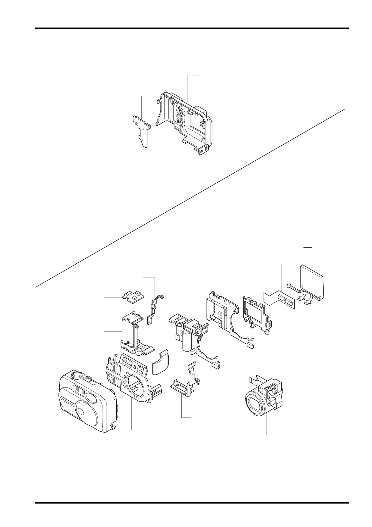
2-2.Names of internal Components
SW PWB ASSY
2. Names of Components
CABI R ASSY
BATTERY LID ASSY
RSW PWB ASSY
BATTERY HOLDER
FRAME L
LCD ASSY
LCDFP PWB ASSY
LCD FRAME
MAIN PWB ASSY
DCST PWB ASSY
FRAME R
CABI F ASSY
CABI INNNER(N.S.)
LENS ASSY
7

3. Disassembly
3. Disassembly
3-1.Removing CABI R ASSY
Remove in the order indicated by circled numbers.
FinePix2600Zoom (U/E/EG) SERVICE GUIDE
<step1>
1
<step2>
(1) Five screws are removed.
(2) Battery lid is opened.
1
2
1
33
(3) CABI R ASSY is removed in the direction of the arrow.
<step3>
8
(4) CN305 is removed.
4
Revised:3.Sep.2001

FinePix2600Zoom (U/E/EG) SERVICE GUIDE
3-2.Removing LCD ASSY,LCD FRAME.
Remove in the order indicated by circled numbers.
<step1>
2
3
3. Disassembly
(1) CN801and CN501 are removed.
(2) Hook of LCD FRAME in two places is removed.
(3) LCD ASSY is removed on the direction of the
arrow.
<step2>
<step3>
1
4
5
7
(4) LCD FP PWB is removed in the direction of the arrow.
(5) Two screws are removed.
(6) Hook of LCD FRAME in two places is removed.
(7) Removes in the direction of the arrow.
6
Revised:3.Sep.2001
9
3. Disassembly
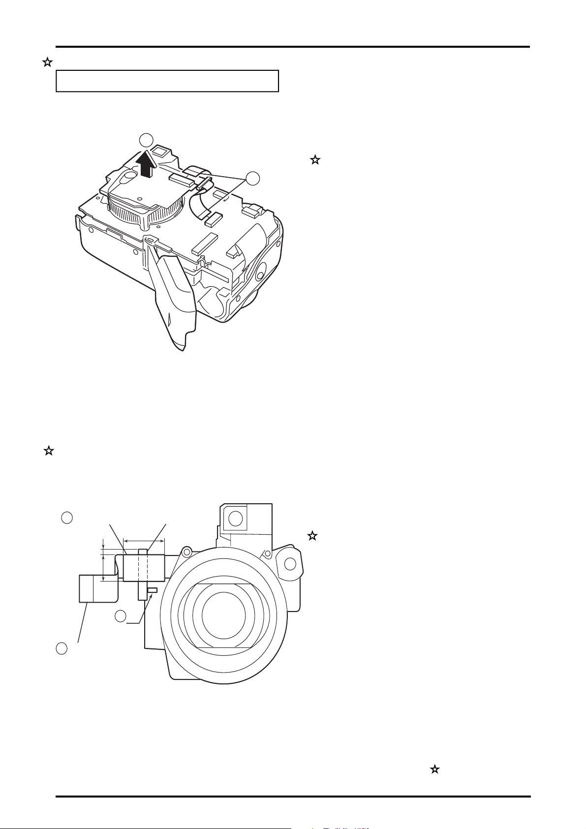
3-3.Removing LENS ASSY.
Remove in the order indicated by circled numbers.
<step1>
FinePix2600Zoom (U/E/EG) SERVICE GUIDE
2
(1) CN1 and CN201 are removed.
(2) LENS ASSY is removed in the direction of the arrow.
1
* Method of installing FERRITE CORE when LENS ASSY is exchanged
3
Insulating tape
2mm
9mm
2
FPC
1
FERRITE CORE
15mm
C2
(1) Match FERRITE CORE to REF.No C2 on the
CCD PWB ASSY.
(2) Pass FERRITE CORE through FPC of LENS ASSY.
(3) Make FERRITE CORE a center, and put insulating
tape of 9mm in width and 15mm in length.
10
Revised:3.Sep.2001
 Loading...