

Page 1
Fuji Medical Dry Laser Imager
For Safe Operation
(DRYPIX 6000)
Reference Guide
8th Edition : February 2017
Product Overview
Basic Operation
Utility
Troubleshooting
Care and
Maintenance
Appendix
897N102437G
Maintenance and
Inspection
This Manual describes details on how to operate the DRYPIX Smart
and cautions to be observed when operating it. Please read this manual
thoroughly before actually operating the DRYPIX Smart After reading this
manual, store it nearby the DRYPIX Smart so that you can see it whenever
necessary.
Page 2

DRYPIX Smart Reference Guide 897N102437G
ii
Page 3

Introduction
CAUTIONS
This manual provides detailed explanations of operation methods and cautions to promote proper
understanding of functions and more effective usage.
Accompanying documents were originally drafted in the English language.
Installation may only be conducted by authorized service personal.
This manual is applicable to the following software.
• DRYPIX Smart Main Software V. 1.0 or later
Indications for use (for U.S.)
Fuji Medical Dry Laser Imager, model DRYPIX Smart (DRYPIX 6000) is indicated for use in
providing diagnostic quality medical images on lm for aid in physician diagnosis, including the
printing of images and associated identication information from various digital imaging source
modalities, including but not limited to,Computed Tomography (CT), Magnetic Resonance Imaging
(MRI), Ultrasound,Computed Radiography, Digital Radiography, Digital Mammography and Nuclear
Medicine.
Intended use (for European Union and other countries.)
Fuji Medical Dry Laser Imager DRYPIX Smart (DRYPIX 6000) is a device that prints digital image
data transferred via the DICOM network from the FCR/FDR Image Reader or DR, CT, MRI and
other imaging modalities onto the Fuji Medical Dry Laser Image Film.
Note : The above statements were determined by applicable medical device regulations which vary
throughout the world. These statements are subject to revision when additional clearance or
approval is obtained.
1. No part or all of this manual may be reproduced in any form without prior permission.
2. The information contained in this manual may be subject to change without prior notice.
3. FUJIFILM Corporation shall not be liable for malfunctions and damages resulting from
installation, relocation, remodeling, maintenance, and repair performed by other than
dealers specied by FUJIFILM Corporation.
4. FUJIFILM Corporation shall not be liable for malfunctions and damages of FUJIFILM Corporation
products due to products of other manufacturers not supplied by FUJIFILM Corporation.
5. FUJIFILM Corporation shall not be liable for malfunctions and damages resulting from
remodeling, maintenance, and repair using repair parts other than those specied by
FUJIFILM Corporation.
6. FUJIFILM Corporation shall not be liable for malfunctions and damages resulting from
negligence of precautions and operating methods contained in this manual.
7. FUJIFILM Corporation shall not be liable for malfunctions and damages resulting from use
under environment conditions outside the range of using conditions for this product such
as power supply, installation environment, etc. contained in this manual.
8. FUJIFILM Corporation shall not be liable for malfunctions and damages resulting from
natural disasters such as res, earthquakes, oods, lightning, etc.
Caution : Rx Only in the United States (Federal law restricts this device to sale by or on the
order of a physician.)
Open-Source Software Used in This Product
This product uses third party’s software that is made available as open source software or free software.
SUCH SOFTWARE IS PROVIDED “AS IS” WITH NO WARRANTY OF ANY KIND AS TO ITS
MERCHANTABILITY OR FITNESS FOR ANY PARTICULAR PURPOSE.
For information on open source software used in this product, please see the attached CD.
Source codes for certain type of open source software used in this product are available at delivery
cost. If you would like to receive such source codes, please contact FUJIFILM dealer or the service
representatives at the agency from which you purchased this product.
(Please be noted that any inquiries concerning the contents of source codes should be directed to
original licensers of open source software.)
Trademark
FCR is a trademark or a registered trademark of FUJIFILM Corporation.
Other holder’s trademarks
All other company names and product names described in this manual are the trademarks or
registered trademarks of their respective holders.
Copyright © 2012-2017 FUJIFILM Corporation. All rights reserved.
DRYPIX Smart Reference Guide 897N102437G
iii
Page 4

DRYPIX Smart Manuals
DRYPIX Smart Reference Guide
DRYPIX Smart Quality Control Function Reference Guide
DRYPIX Smart Quality Control for Mammography Reference Guide
DRYPIX Smart Reference Guide 897N102437G
iv
Page 5

Contents at a Glance
For Safe Operation
Chapter
Chapter
Chapter
Chapter
1
2
3
4
This chapter presents Warnings and Cautions we wish you to observe for the
safe operation of this equipment.
Product Overview
This chapter presents overview and major features of this equipment.
Basic Operation
This chapter describes routine operation procedures, including how to start up/
shut down this equipment and also how to replace a lm pack.
Utility
This chapter describes the lm density calibration, date and time setting as well
as other functions.
Chapter
Chapter
5
6
Appendix
Troubleshooting
This chapter explains how to troubleshoot an error.
Care and Maintenance
This chapter describes daily care and maintenance we wish you to perform so
that you can use the equipment optimally.
Appendix A Specications
This chapter presents major specications of this equipment.
Maintenance and Inspection
DRYPIX Smart Reference Guide 897N102437G
v
Page 6

How to Read This Manual
CAUTIONS
Basic page conguration
Please have a good grasp of the basic page conguration of this Manual, as illustrated below, for
you to use it more efciently.
Operation
procedure
Describes an operation
procedure according to
sequential numbers.
Section title
Shows the title of an
operation procedure
described in the section.
Lead
Describes information we wish you to
know in advance of your operating the
system or information that may help
you to operate it.
3.2 Replacing the Film Pack
When it is printed with the lm in the lm tray set to “0”, “EP1” (Film Tray 1) or “EP2” (Film Tray 2) is
displayed in the Display panel. Prepare Fuji Medical Dry Laser Image Film “DI -HL” or “DI-ML”, pull out
the lm tray, and replace the lm pack.
1 When the lm in the lm tray runs out
during the lm feedin g, the lm being fed is
automatically out put and “EP1” or “EP2” is
displayed in the Display pane l.
2 Press the Enter bu tton and unlock the lm
tray lock.
“oPn” appears on the Display panel.
Be sure to pull the lm tray out o nly
after it has bee n unlocked. Other wise, a
system malfunction wi ll result.
3 When an error occ urs during lm feeding ,
rst the lm being fed i s automatically
output, and the n the error code appe ars on
the Display panel.
When the stand-by Switc h, Enter Button or Utility
Button is pressed to stop the al arm and clear the
error, “EP1” or “EP2” appears on t he Display panel.
4 Pull the lm tray out ca refully (1.), and
remove the protective mat erial together
with the lm cushioning c ardboard (2.).
Discard the removed protect ive material and lm
cushioning cardboard.
Film cushioning
cardboard
Protective material
5 Make sure that the ar row mark on the new
lm pack points to the ba ck side of the lm
tra y.
Film pack side
Check the arrow
mark direction.
6 Raise one end of the l m pack to tear off
the label (1.), and open both ends of the lm
pack (2.), as illustrated.
1. Tear off the label.
2. Open both ends.
Index
A caption that facilitates
you to open a desired
[Chapter] quickly.
3
Basic Operation
Illustrated operation
procedure
Operation steps are
presented in the illustration
following specified order.
Multiple sub-steps that
consist of an operation step
is numbered, 1., 2. .....
DRYPIX Smart Reference Guide 897N102437G
vi
1. Pull out.
2. Remove.
DRYPIX Smart Reference Guide 897N102437G
Page number
Displayed in
conjunction with the
chapter number.
3-3
Page 7

Marks
WARNING
CAUTIONS
HINT
Information items to be observed when you are operating this system and the supplementary
remarks are described in this manual with the respective marks.
For the safe system operation, be sure to observe Warning/Caution.
Indicates hazardous situations that may lead to serious injury or even
death if the precaution is not or could not be followed.
Indicates hazardous situations that may lead to mild or moderate injury
or physical damages if the caution is not or cannot be followed.
Indicates information that should be noted.
Indicates information that may be helpful.
Shows a more detailed operation method or an item that describes additional
information.
Expressions
Messages appear on the display panel as shown below.
● A message displayed on the display panel (sample)
-----------------------------
“U-1”
DRYPIX Smart Reference Guide 897N102437G
vii
Page 8

Contents
Introduction .......................................................................................................................... iii
DRYPIX Smart Manuals ...................................................................................................... iv
Contents at a Glance ............................................................................................................ v
How to Read This Manual ................................................................................................... vi
Chapter 1 For Safe Operation
1.1 Precautions Before Operating This Equipment ......................................................... 1-1
1.1.1 Precautions to be Observed When Using the Electric Medical Equipment................ 1-2
1.2 Safety ........................................................................................................................ 1-3
1.3 Electromagnetic Compatibility (EMC) ........................................................................1-5
1.4 Handling and Storing Cautions for lms for the Fuji Dry Imager ............................... 1-9
1.5 Locations of labels and signs .................................................................................. 1-10
1.5.1 Locations .................................................................................................................. 1-10
1.5.2 Safety and Other Signs ............................................................................................ 1-13
1.6 Equipment Installation Space .................................................................................. 1-14
1.6.1 Installation Space ..................................................................................................... 1-14
1.6.2 Space Required for Maintenance Work .................................................................... 1-14
1.7 Precautions on DRYPIX Smart Operations ............................................................. 1-15
1.7.1 Precautions for Use .................................................................................................. 1-15
1.7.2 Precautions When Outputting Film Prints ................................................................ 1-16
Chapter 2 Product Overview
2.1 Overview of the DRYPIX Smart ................................................................................ 2-1
2.2 Features of the DRYPIX Smart ................................................................................. 2-3
2.3 Units Names and the Functions ................................................................................2-4
2.3.1 DRYPIX Smart Main Unit ...........................................................................................2- 4
2.3.2 Operation Panel ..........................................................................................................2-6
Chapter 3 Basic Operation
3.1 Starting / Shutting Down the Equipment ................................................................... 3-1
3.1.1 Starting the Equipment ...............................................................................................3-1
3.1.2 Shutting Down the Equipment ....................................................................................3-2
3.2 Replacing the Film Pack ............................................................................................3-3
3.3 Replacing Film Tray ...................................................................................................3-6
Chapter 4 Utility
4.1 Utility List ................................................................................................................... 4-1
4.2 Starting Up the Utility ................................................................................................ 4-2
4.3 Quitting the Utility ...................................................................................................... 4-3
4.4 Automatically Calibrating the Film Density ................................................................4-4
4.5 Outputting a QC Test Pattern ....................................................................................4-5
4.6 Resetting the Remaining Film Counter .....................................................................4-6
4.7 Setting the Sensitive Material Correction Parameter ................................................4-7
4.8 Setting the Date and Time ........................................................................................4-9
DRYPIX Smart Reference Guide 897N102437G
viii
Page 9

4.9 Outputting the SMPTE pattern ................................................................................ 4-10
4.10 Outputting the Mammography QC Pattern .............................................................. 4-12
Chapter 5 Troubleshooting
5.1 In Case a Problem May Arise ...................................................................................5-1
5.2 The Equipment Cannot be Powered ON ................................................................... 5-2
5.2.1 The Equipment Does Not Start Up Normally ..............................................................5-2
5.3 The Power to the Equipment Does Not Turn OFF .....................................................5-3
5.4 Error Code List ..........................................................................................................5-4
5.5 When a Film Jam Occurred ......................................................................................5-5
5.5.1 Film jamming when the error code “221” or “223” is displayed ................................. 5-6
5.5.2 Film jamming when the error code “226” or “227” is displayed ................................ 5-10
5.5.3 Film jamming when the error code “228” is displayed .............................................. 5 -11
5.5.4 Film jamming when the error code “230” is displayed .............................................. 5 -12
5.5.5 Film jamming when the error code “232” is displayed .............................................. 5-13
Chapter 6 Care and Maintenance
6.1 Cleaning the Inside and Surroundings of the Equipment .......................................... 6-1
6.1.1 Cleaning a lm tray .....................................................................................................6-2
6.1.2 Cleaning the Air Filter .................................................................................................6-3
6.1.3 Washing the Cleaning Roller (Optional) with Water .................................................. 6-4
6.1.4 Image Verication ...................................................................................................... 6-6
6.2 Users Checksheet (Care and Maintenance).............................................................. 6-7
6.3 About Preventive Maintenance..................................................................................6-8
Appendix A Specications
A.1 Specications ............................................................................................................A-1
A.2 External View and Weight ........................................................................................ A-2
Maintenance and Inspection
DRYPIX Smart Reference Guide 897N102437G
ix
Page 10

DRYPIX Smart Reference Guide 897N102437G
x
Page 11

Chapter 1
WARNING
For Safe Operation
1.1 Precautions Before Operating This
Equipment
Before using this equipment, please read “Precautions Before Operating This Equipment” carefully so
that you can operate it correctly.
Whenever you operate this equipment, be sure to observe those precautions. Failure to do so may
cause you to subject to injuries or property damage to occur.
Do not connect any unspecied device.
This system is classied as a medical device under EC Directive 93/42/EEC.
This equipment has been designed on the assumption that the patient would not
come into direct contact with it or for operation by appropriately trained operator.
The operator of this equipment must comprehend the contents shown in the labels
or on the monitor.
Process waste correctly, as stipulated by local law or any regulations that apply.
When discarding the DRYPIX Smart that incorporates the lithium battery, be sure to
contact a licensed waste disposal contractor because it cannot be disposed of as a
general waste.
Not doing so may cause environmental pollution.
1
For Safe Operation
To install or relocate the equipment, request it to a designated service supplier.
Cautions on Network
After connecting this system to the network with other systems, conrm that the
other systems are not affected. If they are affected, take countermeasures such as
network separation.
Precautions on External Network Connection
When a setting of the network to which the equipment is connected has been
changed, check that the change does not affect the system operation and take
measures if necessary.
The setting change may include the following:
- Change of connection destination
- Addition of devices
- Removal of devices
- Update of devices
- Upgrade of devices
DRYPIX Smart Reference Guide 897N102437G
1-1
Page 12

1.1.1 Precautions to be Observed When Using the Electric
1
For Safe Operation
Medical Equipment
• Do not remodel the equipment.
• In an emergency, disconnect the power plug or the inlet.
Ensure sufcient space around the power plug or the inlet.
• An additional MULTIPLE SOCKET-OUTLET or extension cord shall not be connected to this
device.
• If the network is shut down due to a network device failure or any other cause, image data is no
longer transferred to this device.
DRYPIX Smart Reference Guide 897N102437G
1-2
Page 13

1.2 Safety
WARNING
CAUTIONS
WARNING
Before using the DRYPIX Smart, read this section thoroughly to ensure that you use the product
properly.
Laser Handling Precautions
This equipment is a Class 1 Laser Product (IEC 60825-1/EN 60825-1).
This device contains an embedded laser with the following specication:
Class : 3B
Medium : Semiconductor laser
Wavelength : 659nm (TYP)
Maximum output - Specication of Laser Diode : 130mW (CW)
Maximum output - Fault Condition : 400mW (CW)
Beam emittance : 20°
To prevent the user from being exposed to laser beams, always observe the following
precautions.
● Never remove any covers other than the front cover, right-side cover and bottom right-side
cover of the equipment.
● When opening covers for coping with lm jams, strictly observe procedures set forth in this
manual. Never perform any other procedures.
● Always contact Fujilm service personnel immediately if a malfunction is suspected in the
equipment.
1
For Safe Operation
Use of controls or adjustment or performance of procedures other than those specied herein
may result in hazardous radiation exposure.
Electric Shock Warnings
The power supply to the DRYPIX Smart is AC 100/110/120V in North America and AC
200/220/230/240V in other countries.
To avoid electric shocks, users should always take the following precautions:
● Only allow a trained operator to use the printer.
● Install the printer in a location where it will not be exposed to water.
● Check that the printer is securely earthed.
● Check that all of the cords and cables are completely and securely connected.
● When using the equipment within the environment where the patient may get into touch
with it, optionally connect additional protective earth conductor.
● When using the equipment within the environment where the patient may get into touch
with it, the user must not touch the equipment’s exterior, such as covers and metal
sections, and the patient at the same time. In addition, take care that the patient does not
touch the equipment.
● To avoid risk of electric shock, this equipment must only be connected to a supply mains
with protective earth.
DRYPIX Smart Reference Guide 897N102437G
1-3
Page 14

1
WARNING
CAUTIONS
CAUTIONS
Never remove the printer cover.
The printer contains high-voltage components that could cause an electric shock.
Ventilation precautions
For Safe Operation
Be sure to install this equipment in a well-ventilated environment.
Good ventilation must be ensured (at least 54m3/hour for one unit).
Precaution about High Temperature
Be careful with units where High-temperature Caution Labels are afxed as those units may
be hot during operation.
Declaration of Conformity
This equipment is in conformance with the following standards:
North America
● UL 60601-1
Other countries
● IEC 60601-1/EN60601-1
● IEC 60601-1-2/IEC 60601-1-2
Classication
1) According to the type of protection against electric shock
CLASS 1 EQUIPMENT
2) According to the degree of protection against electric shock
NO APPLIED PART
3) Protection against harmful ingress of water or particulate matter
IP00
4) According to the degree of safety of application in the presence of a ammable anesthetics
mixture with air or with oxygen or nitrous oxide.
Equipment not suitable for use in the presence of a ammable anesthetics mixture with air or
with oxygen or nitrous oxide.
5) According to the mode of operation
CONTINUOUS OPERATION
DRYPIX Smart Reference Guide 897N102437G
1-4
Page 15

1.3 Electromagnetic Compatibility (EMC)
This equipment has been tested and found to comply with the limits for medical devices to the
IEC60601-1-2+A1 (North America), IEC60601-1-2+A1 (EN60601-1-2+A1), IEC60601-1-2, Medical
Device Directive 93/42/EEC (other than North America).
These limits are designed to provide reasonable protection against harmful interference in a typical
medical installation.
This equipment generates, uses and can radiate radio frequency energy and, if not installed and
used in accordance with the instructions, may cause harmful interference to other devices in the
vicinity.
However, there is no guarantee that interference will not occur in a particular installation.
If this equipment does cause harmful interference to other devices, which can be determined by
tuning the equipment off and on, the user is encouraged to try to correct the interference by one or
more of the followingmeasures:
• Reorient or relocate the receiving device.
• Increase the separation between the equipment.
• Connect the equipment into an outlet on a circuit different from that to which the other device(s)
are connected.
Consult the manufacturer or eld service technician for help.
Further information for IEC 60601-1-2 (EN60601-1-2)
1
For Safe Operation
• Medical electrical equipment needs special precautions regarding EMC and needs to be installed
and put into service according to the EMC information provided in the accompanying documents.
• Portable and mobile RF communications equipment should not be used near this medical
electrical equipment, as such communications equipment can affect this equipment and the
images.
• Information regarding the cable affecting EMC is as follows.
Name General Specication
Network Cable Cat5e or more,
UTP type and straight cable
• The use of accessories, transducers and cables other than those specied, with the exception
of transducers and cables sold by FUJIFILM Corporation as replacement parts for internal
components, may result in increased emissions or decreased immunity of the DRYPIX Smart.
• The DRYPIX Smart should not be used adjacent to or stacked with other equipment.
If adjacent or stacked use is necessary, the DRYPIX Smart should be observed to verify normal
operation in the conguration in which it will be used.
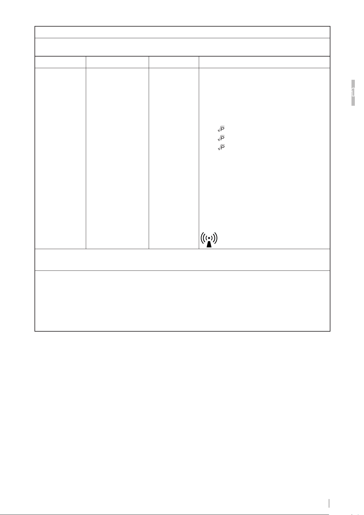
Guidance and manufacturer’s declaration - electromagnetic emissions
The DRYPIX Smart is intended for use in the electromagnetic environment specied below.
The customer or the user of the DRYPIX Smart should assure that it is used in such an environment.
Emissions test Compliance Electromagnetic environment - guidance
The DRYPIX Smart uses RF energy only for its internal
RF emissions
CISPR 11
RF emissions
CISPR 11
Harmonic emissions
IEC61000-3-2
Voltage uctuations/
icker emissions
IEC61000-3-3
Group 1
Class A
Class A
Complies
function.
Therefore, its RF emissions are very low and are not likely
to cause any interference in nearby electronic equipment.
The DRYPIX Smart is suitable for use in all establishments
other than domestic and those directly connected to the
public low-voltage power supply network that supplies
buildings used for domestic purposes.
DRYPIX Smart Reference Guide 897N102437G
1-5
Page 16

Guidance and manufacturer’s declaration - electromagnetic immunity
The DRYPIX Smart is intended for use in the electromagnetic environment specied below.
The customer or the user of the DRYPIX Smart should assure that it is used in such an environment.
Immunity test IEC 60601 test level Compliance level
Electrostatic
1
discharge
(ESD)
IEC61000-4-2
For Safe Operation
Electrical fast
transient/burst
IEC61000-4-4
Surge
IEC61000-4-5
Voltage dips, short
interruptions and
voltage variations on
power supply input
lines
IEC61000-4-11
Power frequency
(50/60Hz) magnetic
eldIEC61000-4-8
NOTE: U
±2kV contact
±4kV contact
±6kV contact
±8kV air
±6kV contact
±2kV air
±4kV air
±8kV air
±2kV for power supply
lines
±1kV for input/output
lines
±1kV differential mode
±2kV common mode
<5% U
T
(>95% dip in UT)
for 0.5 cycle
40% U
T
(60% dip in UT)
for 5 cycles
70% U
T
(30% dip in UT)
for 25 cycles
<5% U
T
(>95% dip in UT)
for 5 s
±2kV for power supply
lines
±1kV for input/output
lines
±1kV differential mode
±2kV common mode
<5% U
T
(>95% dip in UT)
for 0.5 cycle
40% U
T
(60% dip in UT)
for 5 cycles
70% U
T
(30% dip in UT)
for 25 cycles
<5% U
T
(>95% dip in UT)
for 5 s
3 A/m 3 A/m
is the a.c. mains voltage prior to application of the test level.
T
Electromagnetic environment -
guidance
Floors should be wood, concrete or
ceramic tile. If oors are covered with
synthetic material, the relative humidity
should be at least 30%.
Mains power quality should be that
of a typical commercial or hospital
environment.
Mains power quality should be that
of a typical commercial or hospital
environment.
Mains power quality should be that
of a typical commercial or hospital
environment. If the user of the DRYPIX
Smart requires continued operation
during power mains interruptions, it is
recommended that the DRYPIX Smart
be powered from an uninterruptible
power supply or a battery.
Power frequency magnetic elds should
be at levels characteristic of a typical
location in a typical commercial or
hospital environment.
DRYPIX Smart Reference Guide 897N102437G
1-6
Page 17
Guidance and manufacturer’s declaration - electromagnetic immunity
The DRYPIX Smart is intended for use in the electromagnetic environment specied below.
The customer or the user of the DRYPIX Smart should assure that it is used in such an environment.
Immunity test IEC 60601 test level Compliance level Electromagnetic environment - guidance
Conducted RF
IEC61000-4-6
Radiated RF
IEC61000-4-3
3 Vrms
150 kHz to 80 MHz
3 V/m
80 MHz to 2.5 GHz
3 Vrms
3 V/m
Portable and mobile RF communications
equipment should be used no closer to any part
of the DRYPIX Smart, including cables, than the
recommended separation distance calculated from
the equation applicable to the frequency of the
transmitter.
Recommended separation distance
d = 1.2
d = 1.2 80 MHz to 800 MHz
d = 2.3
where P is the maximum output power rating of the
transmitter in watts (W) according to the transmitter
manufacturer and d is the recommended separation
distance in metres (m).
Field strengths from xed RF transmitters, as
determined by an electromagnetic site survey,
should be less than the compliance level in each
frequency range.
vicinity of equipment marked with the following
800 MHz to 2.5 GHz
b
Interference may occur in the
1
For Safe Operation
a
symbol:
NOTE 1: At 80 MHz and 800 MHz, the higher frequency range applies.
NOTE 2: These guidelines may not apply in all situations. Electromagnetic propagation is affected by absorption and
reection from structures, objects and people.
a Field strength from xed transmitters, such as base stations for radio (cellular/cordless) telephones and land
mobile radios, amateur radio, AM and FM radio broadcast and TV broadcast cannot be predicted theoretically with
accuracy. To assess the electromagnetic environment due to xed RF transmitters, an electromagnetic site survey
should be considered. If the measured eld strength in the location in which the DRYPIX Smart is used exceeds
the applicable RF compliance, the DRYPIX Smart should be observed to verify normal operation. If abnormal
performance is observed, additional measures may be necessary, such as reorienting or relocating the DRYPIX
Smart.
b Over the frequency range 150 kHz to 80 MHz, eld strength should be less than 3 V/m.
DRYPIX Smart Reference Guide 897N102437G
1-7
Page 18

Recommended separation distances between
Portable and mobile RF communications equipment and the DRYPIX Smart
The DRYPIX Smart is intended for use in the electromagnetic environment in which radiated RF disturbances are
controlled.
The customer or the user of the DRYPIX Smart can help prevent electromagnetic interference by maintaining a
minimum distance between portable and mobile RF communications equipment (transmitters) and the DRYPIX Smart
as recommended below, according to the maximum output power of the communications equipment.
1
For Safe Operation
Rated maximum output
power of transmitter
0.01 0.12 0.12 0.23
0.1 0.38 0.38 0.73
1 1.2 1.2 2.3
10 3.8 3.8 7.3
100 12 12 23
For transmitters rated at a maximum output power not listed above, the recommended separation distance d in metres
(m) can be estimated using the equation applicable to the frequency of the transmitter, where P is the maximum
output power rating of the transmitter in watts (W) according to the transmitter manufacturer.
NOTE 1: At 80 MHz and 800 MHz, the separation distance for the higher frequency range applies.
NOTE 2: These guidelines may not apply in all situations.
Electromagnetic propagation is affected by absorption and reection from structures, objects and people.
W
Separation distance according to frequency of transmitter
150 kHz to 80 MHz
d = 1.2
m
80 MHz to 800 MHz
d = 1.2
800 MHz to 2.5 GHz
d = 2.3
DRYPIX Smart Reference Guide 897N102437G
1-8
Page 19

1.4 Handling and Storing Cautions for
films for the Fuji Dry Imager
Please be aware of the following cautions for handling and storing of the lm.
Precautions for storing or handling unused lms
1 Use only the “Fuji Medical Dry Laser Image Film DI-HL” or “Fuji Medical Dry Laser Image Film
DI-ML” that is compatible with this equipment. If a lm other than DI-HL or DI-HM is used, a
malfunction may be caused to the equipment.
2 Be sure to store unused lms contained in the lm pack in a cool, dry and dark place of low
temperature and low humidity (temperature: 25°C or lower), avoiding radioactivity and reactive
gases, same as for the conventional wet-type lm.
3 The DI-HL lms are light-sensitive. Do not open a lm pack before it is loaded properly in the
equipment.
4 Do not touch unused lms with bare hands, otherwise adverse effects can appear on recorded
images.
5 Do not take unused lms out of the lm pack that has once been loaded into the equipment and
opened or add lms to the lm pack loaded, which will result in misoperation or failure of the
equipment.
6 The lm pack contains a protective sheet, in addition to the specied number of recording
lms. This protective sheet will remain in the lm pack even after those recording lms have
been printed and it cannot be used for image recording. Because the protective sheet is a lm,
discard it appropriately together with other used lms.
Precautions for storing or handling recorded lms
1
For Safe Operation
1 Store recorded lms in a cool, dry and dark place of low temperature and low humidity. The
higher the temperature and humidity, the more the density of recorded images will change
sharply. Longterm storage at high temperature, high humidity and/or daylight conditions, such
as in a car or room during summer, may cause discoloration. Using lms in the slide projector
or overhead projector will also cause discoloration.
2 For the long-term storage performance of recorded lms, we assume based on the result of the
acceleration test that it will be over 30 years at the storage temperature of 25ºC and over 25
years at 30ºC, until the portion on an image of density (D) = 1.2 at time of output to change 10%
(ΔD =0.12) .
3 After an image has been recorded, the lm immediately after it was ejected from the machine is
still in the process of image development and the room illumination or light emanating from the
viewing boxwill cause slight changes in the optical density. Due to such optical effect, traces
of overlapped lms or transferred images can be visually recognized temporarily, which will
disappear when those lms are left under the normal light condition.
4 Note that lucid surfaces of recorded lms can be lost or traces of contact with any chemicals
that contain water, alcohol, developer, etc., and with other objects that contain a large amount of
salt may appear on images, if they are handled under high-humidity environment or due to such
undesirable contacts.
5 Do not store lms with its image recording faces attached directly for preventing them from
sticking to each other.
DRYPIX Smart Reference Guide 897N102437G
1-9
Page 20

1.5 Locations of labels and signs
Locations of labels and signs afxed to the DRYPIX Smart, and the relevant safety signs are shown
below.
1.5.1 Locations
1
For Safe Operation
Class 3B Panel Label #1
Rating Label
HHS Certification and
Identification Label
Caution Label
Caution Label
(other than North America)
High-temperature
Caution Label
Additional
protective
earth mark
Caution Label Caution Label
Class 3B Panel Label #2
Power
(other than North America)
1-10
DRYPIX Smart Reference Guide 897N102437G
Page 21

North America
1
Class 3B Panel Label #1
For Safe Operation
Rating Label
HHS Certification and Identification Label
Class 3B Panel Labels #2
Be aware that the temperature
may be high in the area where the
following label is affixed.
High-temperature Caution Label
Be sure to use the power cord our
official dealer or local presentative
provided. If an inappropriate cord is
used, it may generate heat or fire.
Caution Label (Inlet)
Do not connect a telephone wire to
the LAN connector. Only UTP-type
straight LAN cables of Category 5e or
higher are appropriate for connection
to this connector.
Caution Label (LAN connector)
DRYPIX Smart Reference Guide 897N102437G
1-11
Page 22

Other countries
1
For Safe Operation
Class 3B Panel Label #1
Rating Label
HHS Certification and Identification Label
Class 3B Panel Labels #2
Be aware that the temperature
may be high in the area where the
following label is affixed.
High-temperature Caution Label
Be sure to use the power cord our
official dealer or local presentative
provided. If an inappropriate cord is
used, it may generate heat or fire.
Caution Label (Inlet)
Do not connect a telephone wire to
the LAN connector. Only UTP-type
straight LAN cables of Category 5e or
higher are appropriate for connection
to this connector.
Caution Label (LAN connector)
Additional Option Tray
1-12
DRYPIX Smart Reference Guide 897N102437G
Identication Label
Page 23
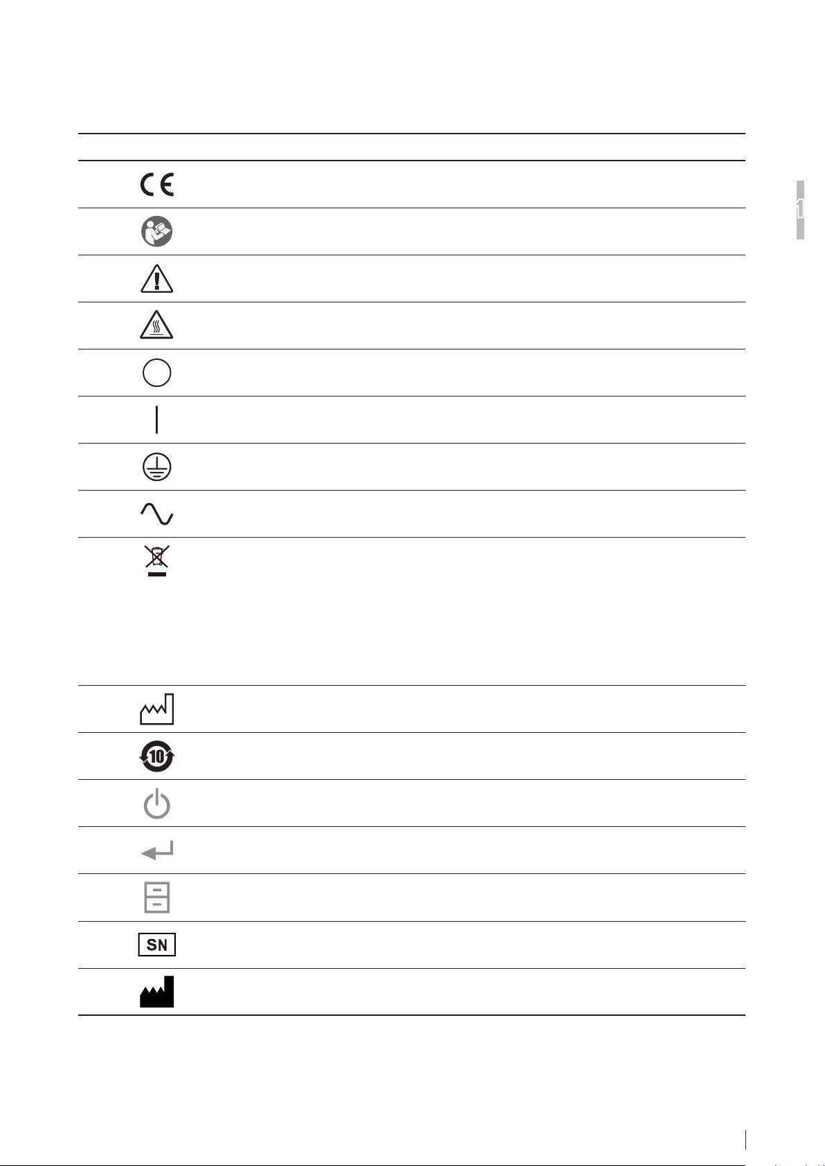
1.5.2 Safety and Other Signs
The following safety signs are used in the DRYPIX Smart labels or on its body.
Sign Description
This symbol indicates compliance of the equipment with Directive 93/42/EEC.
Refer to operation manual
Attention, consult ACCOMPANYING DOCUMENTS.
High-temperature caution
Power-OFF
Power-ON
Protective grounding (to the earth)
1
For Safe Operation
Alternating current
This symbol indicates that this product is not to be disposed of with your household waste,
according to the WEEE Directive (2002/96/EC) and your national law. This product should
be handed over to a designated collection point.
Improper handling of this type of waste could have a possible negative impact on the
environment and human health due to potentially hazardous substances that are generally
associated with EEE.
At the same time, your cooperation in the correct disposal of this product will contribute to
the effective usage of natural resources.
For more information about waste, please contact FUJIFILM dealers.
Year of manufacture
Environmentally Friendly Use Period (EFUP)
Stand-by switch
Enter button
Utility button
Serial number
Manufacture
DRYPIX Smart Reference Guide 897N102437G
1-13
Page 24
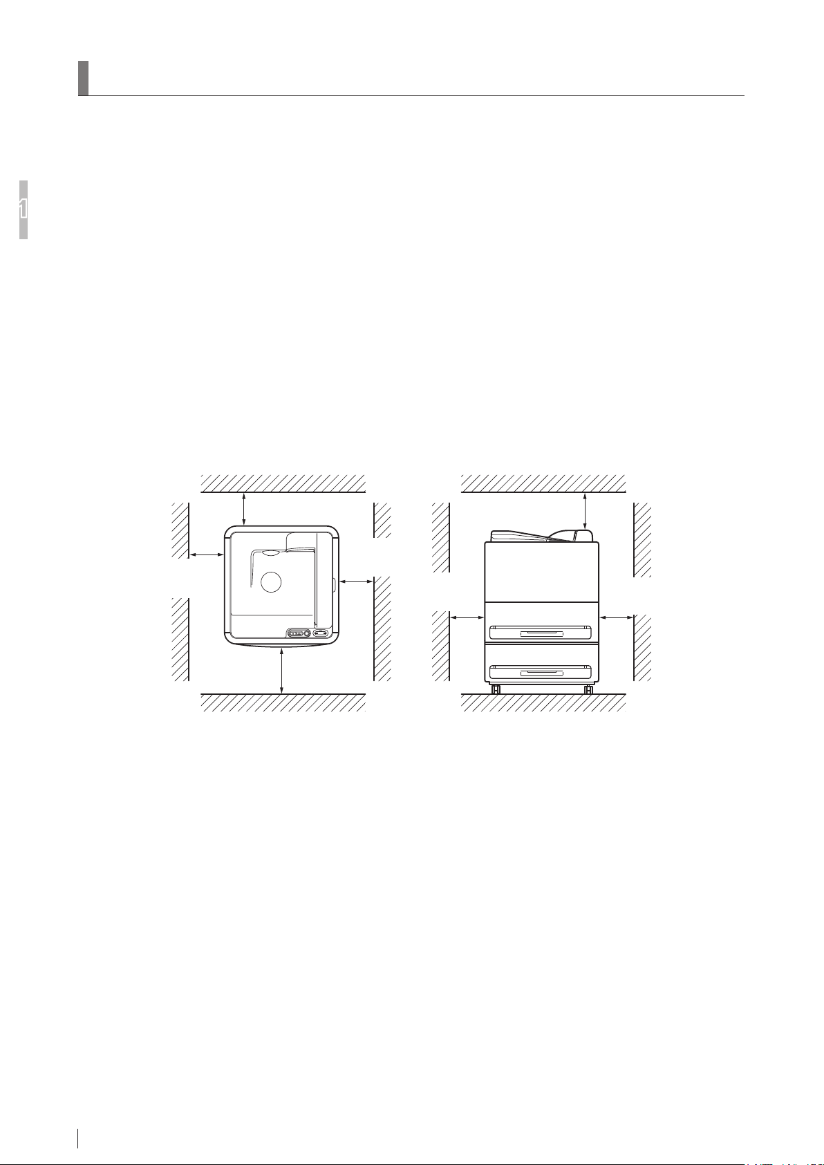
1.6 Equipment Installation Space
1.6.1 Installation Space
When Not Fixed with Fixtures
n
1
For Safe Operation
1.6.2 Space Required for Maintenance Work
Front : More than 800 mm (31.5 in.)
Rear : More than 100 mm (3.9 in.)
Left : More than 50 mm (1.9 in.)
Right : More than 200 mm (7.87 in.)
When Fixed with Fixtures
n
Front : More than 800 mm (31.5 in.)
Rear : More than 100 mm (3.9 in.)
Left : More than 250 mm (9.8 in.)
Right : More than 250 mm (9.8 in.)
Rear : More
than 600 mm (23.6 in.)
Left : More
than 800 mm
(31.5 in.)
Right : More
than 800 mm
(31.5 in.)
Left : More
than 800 mm
(31.5 in.)
Top : More than
400 mm (15.7 in.)
Right : More
than 800 mm
(31.5 in.)
Front : More
than 1000 mm
(39.3 in.)
1-14
DRYPIX Smart Reference Guide 897N102437G
Page 25

1.7 Precautions on DRYPIX Smart
WARNING
CAUTIONS
CAUTIONS
CAUTIONS
CAUTIONS
CAUTIONS
CAUTIONS
CAUTIONS
CAUTIONS
Operations
Operations of image output on lm are performed on the FCR PRIMA Console.
Therefore, no specic operation is required for printout on lm for the DRYPIX Smart system.
1.7.1 Precautions for Use
This printer is not explosion-proof. Do not use ammable or explosive gases near this printer.
When touching the keys of the control panel, be careful not to apply strong mechanical shock
that would damage the keys.
Be sure to check the patient information is printed on a lm.
If the lm cutter breaks, replace it immediately. Take care to avoid injuring yourself on any
sharp edges exposed by the breakage.
The lm cutter is a consumable item. If it breaks, contact our ofcial dealer and have it
replaced.
1
For Safe Operation
Sudden rises in the room temperature when the device is cold may cause dew condensation.
Note that condensation in the device can lead to malfunctions.
Be sure to cut the power supply during inspections.
In the case of failure of the device, rst cut the power supply and display a proper
message (e.g. Out of order) in the device, then contact our ofcial dealer.
Do not lift and move the device. Contact our ofcial dealer when you need to do.
Do not get on the equipment or place any object on it. Otherwise, equipment breakage or
human injury may result.
DRYPIX Smart Reference Guide 897N102437G
1-15
Page 26

1
CAUTIONS
CAUTIONS
CAUTIONS
CAUTIONS
CAUTIONS
WARNING
CAUTIONS
CAUTIONS
HINT
HINT
The weight of the equipment is approximately 104 kg (229.3 lb). Place the equipment in a
location that can bear the weight.
Do not put weight on the lm tray pulled out.
For Safe Operation
When using the shutter, be careful and hold it rmly with both hands to prevent it from
dropping.
When locking a lm tray or cover, be careful not to pinch your ngers or hands.
You may burn yourself if your bracelet or necklace touches high-temperature parts or units,
such as inlet of the Thermal Development Unit.
1.7.2 Precautions When Outputting Film Prints
If the power to the DRYPIX Smart is shut down unintentionally, image printouts may not be
generated.
We, therefore, recommend that you do not erase images stored on the FCR/FDR Image Reader
and other modalities, such as CT, MRI, and the like, before you make sure that images have
been printed properly.
FUJIFILM Corporation and authorized dealers will not assume any responsibility for loss of
images and others.
1-16
Do not forcibly remove a lm in process of ejection.
Removing a lm in process of ejection forcibly may damage it.
Do not open the front cover and right-side cover while images are being processed.
If a cover is opened while in processing, any image being processed at the moment will be
disabled because correct print density cannot be obtained.
If a cover is opened while in processing, the equipment will stop operating for the safety
reason. The alarm will then sound at the same time, displaying on the display panel a error
code saying that a cover is open.
A maximum of 50 lms can be stacked in the output lm tray.
Remove the output lms before the lm tray becomes full.
Install this equipment in a well-ventilated place.
DRYPIX Smart Reference Guide 897N102437G
Page 27

Chapter 2
Product Overview
2.1 Overview of the DRYPIX Smart
Example of system conguration
n
The DRYPIX Smart is a device that prints digital image data, transferred via the DICOM network from
the FCR/FDR Image Reader or DR, CT, MRI and other imaging modalities, onto a lm.
It is also possible to print image information derived from imaging modalities or image processors not
connected to the DICOM network.
Accessory equipment connected to the analog and digital interfaces must be certied according to
the respective IEC standards (i.e. IEC 60950 for data processing equipment and IEC 60601-1 for
medical equipment).
Furthermore all congurations shall comply with the system standard IEC 60601-1-1 and IEC
60601-1 Chapter 16. Everybody who connects additional equipment to the signal input part or
signal output part congures a medical system, and is therefore, responsible that the system
complies with the requirements of IEC 60601-1-1 and IEC 60601-1 Chapter 16. If in doubt, consult
the technical services department or your local representative.
Use an IEEE 802.3 conformant HUB.
2
Product Overview
DRYPIX Smart Reference Guide 897N102437G
2-1
Page 28

2
Product Overview
The gure below shows an example of a DRYPIX Smart connected to a network.
DRYPIX Smart
Network Configuration
CT or MRI
(Modality)
Console Advance
(DR-ID 300CL)
PRIMA T2
(CR-IR 392)
DRYPIX Smart Reference Guide 897N102437G
2-2
Page 29

2.2 Features of the DRYPIX Smart
This section describes the main features of the Fuji Medical Dry Laser Imager DRYPIX Smart.
● This equipment adopts a system that records images with the laser and develops them by means
of thermal processing, doing away with the need for management or replenishment of processing
chemicals and disposal of waste solutions.
This equipment thus uses an environment-friendly system.
● There is no need for darkrooms since the lm packs can be replaced in bright locations.
● You can set up power saving mode to save power consumption of the equipment.
● When a lm jams, you can correct it by opening covers as necessary.
2
Product Overview
DRYPIX Smart Reference Guide 897N102437G
2-3
Page 30

2.3 Units Names and the Functions
This section names each of the DRYPIX Smart components and explains their functions.
2.3.1 DRYPIX Smart Main Unit
(7)
2
Product Overview
(1)
(2)
(5)
(3)
(6)
(4)
(8)
(9)
(13)
(10)
(11)
Name Function
(1)
Operation panel Operation panel for the DRYPIX Smart.
(2)
Front cover Open this cover when a lm jam occurs inside the equipment, and take
appropriate actions to correct lm jamming.
(3)
Film tray 1 A lm pack containing new lms is loaded here.
(4)
Film tray 2
(5)
Slot 1
(6)
Slot 2
(7)
Output lm tray Ejected output lms are stacked in this lm tray.
(8)
Right-side cover Open this cover when a lm jam occurs inside the equipment, and take
(9)
Bottom right-side cover
(10)
LAN connector Connected to the image network devices.
(11)
Power inlet Power inlet for this equipment.
(12)
Main power switch Basically leave this switch turned ON ( I ).
(13)
Additional protective earth
terminal
Note that basically this lm tray is locked.
For details on how to replace a lm pack or pull out the lm tray, see
Pages 3-3 and 3- 6 respectively.
A slot to insert the lm tray.
Up to 50 lms can be stacked.
If the stack exceeds 50 units, it may fall over.
appropriate actions to correct lm jamming.
10base-T/100base-TX/1000base-T Interface
ON ( I ) : Main Power ON
OFF ( O ) : Main Power OFF
Additional protective earth terminal that the service engineer connects
according to the system specications.
(12)
DRYPIX Smart Reference Guide 897N102437G
2-4
Page 31

CAUTIONS
Never open lm tray or covers during processing.
CAUTIONS
CAUTIONS
When closing covers, be careful not to pinch your nger in the aperture.
Do not connect telephone lines to LAN connector.
Only UTP-type straight LAN cables of Category 5E or higher are appropriate for connection to
this connector.
2
Product Overview
DRYPIX Smart Reference Guide 897N102437G
2-5
Page 32

2.3.2 Operation Panel
(1)(2)(3)(4)
(5)
2
Product Overview
Name Function
(1)
Stand-by switch When the stand-by switch is on, you can use this button to startup or shutdown
the DRYPIX Smart.
(2)
Display panel Error code and the number of lms remaining in each lm tray are displayed here.
Items shown below may also be displayed during printing.
Indication Description
888 The equipment is starting up.
ooo
o
x The equipment is being initialized (x is the
Pro Printing is in progress.
oPn The lm tray is unlocked.
PUL The lm tray is locked.
SLP The equipment is in the sleep mode.
oFL The service utility is running.
EP1/EP2/0-1/0-2 No more film
0~150 Display of the number of film sheets remaining
End The equipment is shutting down.
U-0~U-7 User utility
SL1/SL2 Tray selection during the user utility
ESC Cancel user utility
--- Tray retract indication
(Between power-on and the initialization start)
The equipment is being initialized.
estimated time to boot up)
(Under work by a service engineer)
* Normally tray 1. Press the “Enter button” on
the operation panel to display Tray 2.
(3)
Enter button Unlocks the lm tray when the lm is empty or shutter is inserted.
(4)
Utility button Pressing this button will enter Utility mode.
(5)
Pilot lamp Shows whether the main power is ON or OFF.
DRYPIX Smart Reference Guide 897N102437G
2-6
If pressed when the number of sheets remaining is displayed, the number of
sheets remaining in lm tray 2 will be displayed.
It also will determine the operation to go to the next step in the Utility mode.
Lit : The main power is on.
Off : The main power is off.
Page 33

Chapter 3
HINT
Basic Operation
3.1
Starting / Shutting Down the Equipment
3.1.1 Starting the Equipment
1 Switch on the main power supply switch.
Press.
Main Power Switch
The pilot lamp turns on.
2 Touch the stand-by Switch on the
Operation Panel.
The DRYPIX Smart equipment starts running in
about 10 to 15 minutes after the stand-by
switch has been touched on the Operation
Panel. See page 5-2 if the equipment does not
start running properly.
Display panel will display “888” → “ooo” → “o x” →
… → “o 1” while the printer is starting up.
Press.
3
Basic Operation
If the Main Power Switch is set to the “I” side, it is
in the ON status.
3 When the equipment starts up, the number
of remaining lm sheets appears on the
display panel.
DRYPIX Smart Reference Guide 897N102437G
3-1
Page 34

CAUTIONS
CAUTIONS
3.1.2 Shutting Down the Equipment
3
Basic Operation
See page 5-3 if the equipment does not shut down
properly.
When “End” is displayed, the equipment
is shutting down.
Do not turn off the main power switch
when “End” remains displayed,
otherwise the equipment may
malfunction.
Do not turn off the main power switch
until the “End” display disappears. The
time period of the “End” display depends
on the setting (approx. 10 to 30 sec.)
If “End” has been displayed for more
than 10 minutes, an error may have
occurred in the equipment. Turn the Main
Power Switch off and contact Fujilm
service personnel.
1 Hold down the stand-by Switch on the
Operation Panel for a few seconds.
Press.
“End” appears on the Display panel.
DRYPIX Smart Reference Guide 897N102437G
3-2
If you want to reboot the equipment, wait
for about 10 seconds or longer after the
equipment has been shut down, and then
touch the stand-by Switch.
This is to fully reset the system status inside
the equipment.
Page 35

3.2 Replacing the Film Pack
HINT
CAUTIONS
When it is printed with the lm in the lm tray set to “0”, “EP1” (Film Tray 1) or “EP2” (Film Tray 2) is
displayed in the Display panel. Prepare Fuji Medical Dry Laser Image Film “DI-HL” or “DI-ML”, pull out
the lm tray, and replace the lm pack.
1 When the lm in the lm tray runs out
during the lm feeding, the lm being fed is
automatically output and “EP1” or “EP2” is
displayed in the Display panel.
Use the procedure described below when the
same lm is loaded in both the lm tray 1 and the
lm tray 2.
* The service setting is required in advance.
1. When the lm in either of the lm trays runs
out, “0-1” appears for the lm tray 1 and “0-2”
for the lm tray 2 on the Display panel, and an
alarm sounds. Press the Utility button twice to
stop the alarm and start up the utility.
2. Press the Enter button while “U-0” is
displayed on the Display panel.
2 Press the Enter button and unlock the lm
tray lock.
“oPn” appears on the Display panel.
Be sure to pull the lm tray out only
after it has been unlocked. Otherwise, a
system malfunction will result.
3 Pull the lm tray out carefully (1.), and
remove the protective material together
with the lm cushioning cardboard (2.).
Discard the removed protective material and lm
cushioning cardboard.
Film cushioning
cardboard
Protective material
3
Basic Operation
3. Press the Utility button to select the slot.
4. Select the slot and press Enter button to
unlock the lm tray lock. Go to Step
2
2. Remove.
1. Pull out.
4 Make sure that the arrow mark on the new
lm pack points to the back side of the lm
tray.
Film pack side
.
Check the arrow
mark direction.
DRYPIX Smart Reference Guide 897N102437G
3-3
Page 36

5 Raise one end of the lm pack to tear off
CAUTIONS
CAUTIONS
CAUTIONS
3
Basic Operation
the label (1.), and open both ends of the lm
pack (2.), as illustrated.
1. Tear off the label.
2. Open both ends.
Make sure to cut off the heat-sealed part of
the pack.
If the lm cutter’s blade protection is
broken, the blade will be exposed posing
then danger to the user.
Do not touch the unprotected blade.
Replace a dull lm cutter hard to cut the
lm pack, as necessary.
7 Slowly push the lm tray in until it locks
rmly.
6 Use the lm cutter stored on the right-
hand side of the Operation Panel (1.) to cut
the lm pack along the lm tray edge (2.).
Replace then the lm cutter in the position
where it has been stored (3.).
The lm cutter is a consumable item. If the lm
cutter no longer cuts lm properly or is damaged,
contact our ofcial dealer.
Film cutter
1. Take out.
3. Replace.
2. Cut.
Push in slowly.
When closing the lm tray, be careful not
to pinch your ngers.
8 Make sure that “PUL” is displayed on the
Display panel.
9 Gently and slowly pull out straight toward
you one lm pack end that is outside the
lm tray.
This completes the lm supply procedure.
DRYPIX Smart Reference Guide 897N102437G
3-4
Heat-sealed part
Pull out.
Page 37

CAUTIONS
An attempt to pull the lm pack out at a
CAUTIONS
HINT
HINT
slant or roughly will cause it to break.
When “Waiting for size exchange” or
“Film size error” is displayed on the
status bar of “Queue list” in the image
processor, check the display panel of
the DRYPIX Smart and take the following
measures.
– If “oPn” is displayed on the display
panel, no lm is remaining in the lm
tray. Load new lm.
– When the number of remaining
lm sheets appears on the display
panel, replace the tray with one of a
different lm size or check the lm
size of the image processor.
3
Basic Operation
When a lm pack is installed, the automatic lm
density calibration starts and when it nishes, the
number of remaining lm sheets will be displayed.
The number of lm sheets in the lm tray will be
changed.
When an error occurs during lm feeding, rst the
lm being fed is automatically output, and then
the error code appears on the Display panel.
When the stand-by Switch, Enter Button or Utility
Button is pressed to stop the alarm and clear
the error, “EP1” or “EP2” appears on the Display
panel.
DRYPIX Smart Reference Guide 897N102437G
3-5
Page 38

3.3 Replacing Film Tray
CAUTIONS
HINT
CAUTIONS
CAUTIONS
CAUTIONS
CAUTIONS
CAUTIONS
When you are pulling out a lm-loaded tray, insert the shutter to avoid exposure to lm.
3
1
Basic Operation
The table below shows the replaceable
lm trays.
The table below shows the replaceable lm trays.
35 × 43 cm (14” × 17”), 35 × 35 cm (14” × 14”)
26 × 36 cm (10” × 14”), 25 × 30 cm (10” × 12”)
20 × 25 cm (8” × 10”) *
* 26 × 36 cm (10” × 14”), 25 × 30 cm (10” × 12”)
and 20 × 25 cm (8” × 10”) lms can be used
together by the option setting.
Carefully place the shutter in the slit at the top
of the lm tray and fully insert it to the end.
Check that the Display panel is displaying the number
of remaining lm sheets when inserting the shutter.
Insert.
The lm tray 1 will be unlocked when the
shutters are inserted into both the lm
tray 1 and the lm tray 2.
The lm tray can only be unlocked
manually when the following conditions
are met.
● The device is in the idling state.
● There is one or more lm remaining
in the lm tray.
● The shutter is inserted.
● The lm tray is inserted.
Under any of the following conditions,
the lm tray cannot be unlocked
manually.
● An image is being printed.
● The Utility mode is running.
● An error code is being displayed.
The lm tray cannot be unlocked
manually during the starting,
initializing or exiting the device.
3 Pull out the lm tray together with the
shutter until it stops, and then slightly lift
the tray to completely pull it out.
The shutter is stored in the rear-side of the
DRYPIX Smart.
● When inserting the shutter, be careful
and hold it rmly with both hands to
prevent it from dropping.
● When inserting or removing the
shutter, take care that your hands are
not caught between the parts.
2 Press the Enter Button.
When the target lm tray is unlocked, “oPn” appears
on the Display panel.
Pull out.
When pulling out the lm tray, be careful
not to press the lock release button at the
back.
Normally, the lm tray is locked and
cannot be pulled out as is. Do not forcibly
pull out the tray. First press the Enter
Button and make sure that “oPn” appears
on the Display panel, and then pull out
the tray.
3-6
DRYPIX Smart Reference Guide 897N102437G
Page 39

CAUTIONS
Do not remove the shutter while
CAUTIONS
HINT
CAUTIONS
HINT
CAUTIONS
CAUTIONS
replacing.
When you remove the lm tray, hold it
rmly with your hands, and exercise care
not to drop it on the oor.
The maximum weight of the lm tray,
including lms, is approx. 8 kg (17. 3 l b).
● When removing the shutter, be careful
and hold it rmly with both hands to
prevent it from dropping.
● When inserting or removing the
shutter, take care that your hands are
not caught between the parts.
The number of lms remaining in the lm tray when
the tray is pulled out appears on the Display panel.
4 Insert the specied lm tray together with
the shutter.
Reinsert.
“PUL” appears on the Display panel.
5 Push the lm tray in rmly and make sure
that the lm tray has been locked correctly.
Remove then the shutter.
To remove the shutter when the lm tray is not
inserted, press the lock release button at the back.
Film tray
3
Basic Operation
Lock release button
If the shutter is removed when lm
remains in the lm tray, the lm may be
exposed.
When an unregistered lm tray is inserted
or a different lm tray is inserted, “219”
appears on the Display panel and lm tray
is automatically unlocked.
Insert a different lm tray.
Remove.
Store the shutter in the rear-side of the DRYPIX
Smart.
DRYPIX Smart Reference Guide 897N102437G
3-7
Page 40

3
Basic Operation
DRYPIX Smart Reference Guide 897N102437G
3-8
Page 41

Chapter 4
HINT
Utility
4.1 Utility List
Following are the functions available in the Utility mode. For details of the function operation
procedures, see the respective pages for referencing shown in the owchart below.
Utility
Startup
Page 4-2
Quitting
Page 4-3
Automatically Calibrating
the Film Density
Page 4-4
QC
QC Test Pattern
Film Reprint
Page 4-5
Resetting the
Remaining Film Counter
Reset Remaining
Film Counter
Page 4-6
Setting Sensitive Material
Correction Parameters
Page 4-7
Setting the Date and Time
Density of print lms can be calibrated automatically.
* Displayed only when the function has been activated in the
service setting.
It is possible to print test pattern lms that are required
for achieving image Quality Control.
The number of remaining lm sheets can be reset.
The sensitive material correction parameter can be set.
4
Utility
Date and Time
Page 4-9
Outputting the
SMPTE pattern
Page 4-10
Outputting the
Mammography QC Pattern
Page 4-12
The table below shows the buttons available when the printer has switched to Utility mode.
Utility button
Set button
Switch to Utility mode.
In the Utility mode, you can “display the next option”.
You can “confirm or execute the current option and proceed to the next
step”.
The date of the clock incorporated in this device can be
set.
To check the gray scale, the SMPTE pattern can be
output.
The test pattern necessary for quality check of the
image can be output.
DRYPIX Smart Reference Guide 897N102437G
4-1
Page 42

4
4.2 Starting Up the Utility
Utility functions that the DRYPIX Smart system offers allow you to operate detailed processing or
perform various settings.
Note that the Utility functions cannot be used while the equipment is in process of image printout.
1 Press the Utility button.
The display panel changes.
Utility
DRYPIX Smart Reference Guide 897N102437G
4-2
Page 43

4.3 Quitting the Utility
Shown below is the procedure to quit the Utility mode.
1 Display the number or remaining lm
sheets in either operation, and exit from the
Utility.
Press the Utility button few times.
•
Press the Enter button when “ESC” is displayed.
•
10 seconds have elapsed without any operation
•
4
Utility
DRYPIX Smart Reference Guide 897N102437G
4-3
Page 44

4.4 Automatically Calibrating the Film
Density
This function is used to calibrate the lm density so that lms are printed according to the density
gradation curve value determined in the equipment.
Use this function when the lm manufacturing number has been changed or the output density has changed.
4
Utility
1 Press the Utility button.
The Display panel changes and shows “U-1”.
2 Press the Enter button while “U-1” is
displayed.
4 Select the slot and press Enter button.
Auto gray level correction will be executed.
“U-1” in the Display panel blinks when auto gray
level correction is executed.
Test pattern lm (14”×17”)
The slot 1 is displayed.
3 Press the Utility button to select the slot.
Test pattern lm (26×36cm)
5 When a test pattern is printed, the Utility
mode automatically exits and the equipment
becomes ready for printing again.
DRYPIX Smart Reference Guide 897N102437G
4-4
If an error occurs, see the Chapter 5.
Page 45

4.5 Outputting a QC Test Pattern
A QC test pattern can be output.
For details, see the “DRYPIX Smart Quality Control Function Reference Guide”.
1 Press the Utility Button twice.
The Display panel changes and shows “U-2”.
2 Press the Enter button while “U-2” is
displayed.
4 Select the slot and press Enter button.
QC output is executed.
“U-2” blinks when QC output is executed.
For detailson the QC function, see [DRYPIX
Smart Quality Control Function Reference
Guide].
5 When a QC test pattern is output, the
Utility mode automatically exits and the
equipment becomes ready for printing
again.
4
Utility
The slot 1 is displayed.
3 Press the Utility button to select the slot.
CAUTION
If an error occurs, see the Chapter 5.
DRYPIX Smart Reference Guide 897N102437G
4-5
Page 46

4.6
CAUTIONS
CAUTIONS
The number of remaining lm sheets can be reset.
Resetting the Remaining Film Counter
4
Utility
1 Press the Utility Button 3 times.
The Display panel changes and shows “U-3”.
2 Press the Enter button while “U-3” is
displayed.
The slot 1 is displayed.
4 Select the slot and press Enter button.
The Remaining Film Counter is reset and “0” is
displayed in the display panel.
● The cumulative number of used lms
will not be reset.
● If the lm tray is not inserted, an alarm
sounds and the number of remaining
lm sheets cannot be reset.
5 When the number of remaining lm sheets
is reset, the Utility mode automatically
exits.
3 Press the Utility button to select the slot.
When an error occurs, the error code
appears. When the error is cleared, the
Utility mode automatically exits.
DRYPIX Smart Reference Guide 897N102437G
4-6
Page 47

4.7 Setting the Sensitive Material
CAUTIONS
CAUTIONS
Correction Parameter
The sensitive material correction parameter can be set.
4 Select the slot and press Enter button.
Use this function only when instructed to
do so by Fujilm service personnel. Do not
use this without being instructed to do so.
1 Press the Utility Button 4 times.
The tenth digit of the rst half (consisting of two
numbers) of the sensitive material correction
parameter blinks.
4
The Display panel changes and shows “U- 4”.
2 Press the Enter button while “U-4” is
displayed.
The slot 1 is displayed.
3 Press the Utility button to select the slot.
If the lm tray is not inserted, an alarm
sounds and the sensitive material
correction parameter cannot be set.
5 Press the Utility button.
Every time the User Utility Button is pressed, the
tenth digit of the rst half (consisting of two numbers)
of the sensitive material correction parameter
increases in steps of 1.
6 Press the Enter Button.
Utility
The rst digit of the rst half (consisting of two
numbers) of the sensitive material correction
parameter blinks.
DRYPIX Smart Reference Guide 897N102437G
4-7
Page 48

4
7 Press the Utility button.
Every time the User Utility Button is pressed, the
rst digit of the rst half (consisting of two numbers)
of the sensitive material correction parameter
increases in steps of 1.
8 Press the Enter Button.
Utility
The tenth digit of the last half (consisting of two
numbers) of the sensitive material correction
parameter (identied as the last two digits) blinks.
9 Repeat Steps
digits of the sensitive material correction
parameter.
10
Pressing the Enter Button determines the
sensitive material correction parameter,
and the Utility mode automatically exits
and equipment becomes ready for printing
again.
3
to 5 to set the last 2
DRYPIX Smart Reference Guide 897N102437G
4-8
Page 49

4.8 Setting the Date and Time
The date of the clock incorporated in this device can be set.
1 Press the Utility Button 5 times.
The Display panel changes and shows “U-5”.
2 Press the Enter Button.
4 Press the Enter Button.
The rst digit of “Year” blinks.
5 Press the Utility button.
4
Utility
The tenth digit of “Year” blinks.
3 Press the Utility button.
Every time the User Utility Button is pressed, the
tenth digit of “Year” increases in steps of 1.
Every time the User Utility Button is pressed, the
tenth digit of “Year” increases in steps of 1.
6 Press the Enter Button.
The tenth digit of “Month” blinks.
7 Repeat Steps
parameters of month, day, hour and minute.
3
to 5 four times to set
8 Pressing the Enter Button determines
the date and time, and the Utility mode
automatically exits and equipment
becomes ready for printing again.
DRYPIX Smart Reference Guide 897N102437G
4-9
Page 50

4.9 Outputting the SMPTE pattern
To check the gray scale, the SMPTE pattern can be output.
4
Utility
1 Press the Utility Button 6 times.
The Display panel changes and shows “U- 6”.
2 Press the Enter button.
5 Press the Utility button to select the slot.
6 Select the slot and press Enter button.
Display panel will switch to setting of the SMPTE
pattern.
3 Press the Utility button to set the SMPTE
pattern.
Each press of the Utility button switches the setting
for the SMPTE pattern (1 - 5).
4 Press the Enter button.
“U- 6” blinks while the output of SMPTE pattern is
output.
4-10
The slot 1 is displayed.
DRYPIX Smart Reference Guide 897N102437G
Page 51

CAUTIONS
Output patterns differ depending on the
default settings of the equipment.
To change the output patterns, consult
FUJIFILM service personnel.
7 When the SMPTE pattern is output, and
the Utility mode automatically exits and
equipment becomes ready for printing
again.
4
Utility
DRYPIX Smart Reference Guide 897N102437G
4-11
Page 52

4.10
The mammography QC pattern can be output.
Refer to “DRYPIX Smart Quality Control for Mammography Reference Guide” for more information.
Outputting the Mammography QC Pattern
4
Utility
1 Press the Utility button 7 times.
The display panel changes and shows “U-7”.
2 Press the Enter button.
4 Press the Enter button.
The slot 1 is displayed.
5 Press the Utility button to select the slot.
Display panel will switch to setting of the
mammography QC pattern.
3 Press the Utility button to set the
mammography QC pattern.
Each press of the Utility button switches the setting
for the mammography QC pattern.
“E-1”→“E-2 ”→…→“ E-7 ”→“n -1”→“n-2 ”→…→
“n - 5”→“ ESC”
Panel
display
E-1 TG18-QC n-1 TG18- QC
E-2 TG18-P QC n-2 TG18 - PQC
E-3 TG18-P QC (HIGH) n-3 17-Steps
E-4 TG18 -UN80 n-4 Grid
E-5 TG18 -UN10 n-5 Special Resolution
E-6 TG18 -UNL80
E-7 T G18 - U NL1 0
Image name
Panel
display
Image name
Each press of the Utility button switches the setting
for the mammography QC pattern.
(“ E-1”→“E-2”→…→“n-1”→“ n-2”→…→“ESC”)
6 Select the slot and press Enter button.
“U-7” blinks while the output of mammography QC
pattern is output.
4-12
DRYPIX Smart Reference Guide 897N102437G
Page 53

7 If outputting a mammography QC pattern,
the Utilities are terminated automatically,
and the device returns to a status where
you can print.
When an error occurs, refer to Chapter 5.
4
Utility
DRYPIX Smart Reference Guide 897N102437G
4-13
Page 54

4
Utility
4-14
DRYPIX Smart Reference Guide 897N102437G
Page 55

Chapter 5
Troubleshooting
5.1 In Case a Problem May Arise
When the equipment does not operate normally, see the relevant page for you to take necessary
actions appropriately, according to the symptom shown below.
If the problem cannot be solved, contact Fujilm service personnel.
In Case a Problem May Arise
The Equipment Cannot be Powered ON
The Power to the Equipment Does Not Turn OFF
Error Code List
When a Film Jam Occurred
Jam Position : Film Tray
Jam Position : Conveyance Unit
Jam Position : Recording Unit
Jam Position : Thermal Development Unit
Jam Position : Ejection Unit
Page 5-2
Page 5-3
Page 5-4
Page 5-5
Page 5-6
5
Page 5-10
Troubleshooting
Page 5-11
Page 5-12
Page 5-13
DRYPIX Smart Reference Guide 897N102437G
5-1
Page 56

5.2
The Equipment Cannot be Powered ON
The equipment cannot be powered ON even at the press of the stand-by Switch.
5
5.2.1 The Equipment Does Not Start Up Normally
Troubleshooting
The Main Power
Switch has been
turned OFF.
The power cord has
been disconnected.
Set the Main Power Switch to the “|”
side to turn it ON.
When power is supplied, the pilot lamp
lights up.
Main Power Switch
Turn the Main Power Switch OFF and
then plug the power cord rmly in the
outlet.
Turn the Main Power Switch on and
then press the Stand-by switch. When
power is supplied, the pilot lamp lights
up.
Even though the power has been turned ON, the equipment does not start up normally.
Press.
Nothing appears on the Display panel
Contact FujiFilm service personnel.
An error code appears while the device is in the process of startup
An equipment cover is
open.
The lm tray is pulled
out.
The shutter is inserted
in a lm tray.
When the cover is open or mistakenly opened during the startup, an alarm
sounds and the error code “201” appears on the Display panel.
Press the stand-by Switch, Enter Button or Utility Button to stop the alarm,
and then close the cover. When the cover is closed, the device reboots.
When the film tray is pulled out, an alarm sounds and the error code “203” or
“207” appears on the Display panel. Press the stand-by Switch, Enter Button
or Utility Button to stop the alarm. Contact Fujifilm service personnel as the
film tray may be defective.
When the shutter is inserted, an alarm sounds and the error code “204”, “208”,
“205” or “209” appears on the Display panel. Press the stand-by Switch,
Enter Button or Utility Button to stop the alarm and remove the shutter on the
film tray. Remove the shutter to reboot the device.
DRYPIX Smart Reference Guide 897N102437G
5-2
Page 57

5.3 The Power to the Equipment Does Not
CAUTIONS
Turn OFF
The device does not exit even if the stand-by Switch is held down for a few seconds.
An error code does not appear
An unprocessed
lm remains in the
equipment.
“End” remains displayed for more than 10 minutes.
10 minutes or more
has passed since
“End” appears on the
display panel.
Normally “End” is displayed for 10 to 30 seconds after pressing the Stand-by switch. Do not
turn off the Main Power Switch during this period, otherwise the equipment may malfunction.
After the film output is finished, hold down the stand-by switch for a few
seconds and then turn the power off.
Turn OFF (press to the O side) the
Main Power Switch at the bottom
right-side corner on the side of the
equipment.
Press.
Main Power Switch
5
Troubleshooting
DRYPIX Smart Reference Guide 897N102437G
5-3
Page 58

5
CAUTIONS
Troubleshooting
5.4 Error Code List
When an error occurs on the device, an alarm sounds and the error code appears on the Display
panel.
Press the stand-by Switch, Enter Button or Utility Button to stop the alarm.
The error codes appearing on the Display panel are listed below.
Error code Actions
201 Check that the right side cover is closed, and close the front cover.
203/207 Load the tray. (Slot 1/Slot 2)
204/208 Remove the shutter. (Slot 1/Slot 2)
206/210 Release the tray lock after inserting the shutter. (Slot 1/Slot 2)
211 An error has occurred with the auto density measurements. Try again.
212 An error has occurred with the density measurements of the QC print. Try again.
213
214
215 The lm size is different. Set the tray with 14”x17” lm loaded.
216 The lm size is different. Set the tray with 14”x14” lm loaded.
217 The lm size is different. Set the tray with 10”x14” lm loaded.
218 The lm size is different. Set the tray with 10”x12” lm loaded.
219 The lm size is different. Set the tray with 8”x10” lm loaded.
220 An unregistered tray has been set.Set a registered tray.
221/223 The lm has become jammed in the sheet-feeder. Remove the lm. (Slot 1/Slot 2)
226/227 The lm has become jammed in the conveyance unit. Remove the lm.
228 The lm has become jammed in the recording unit. Remove the lm.
230 The lm has become jammed in the thermal development unit. Remove the lm.
232 The lm has become jammed in the discharge unit. Remove the lm.
244 Reading of a barcode has failed. Load the tray again.
245 A different barcode has been detected. Load correct lms.
246 Films with a different base color have been loaded. Load correct lms.
249
660 Contact your dealer for servicing.
The end of the operating life of the laser is close, however it can still be used. Note that
the printer will need to be serviced, so contact your dealer.
The end of the operating life of the laser has expired. The printer will need to be serviced,
so contact your dealer.
A tray for a lm size different from the setting has been loaded. Load the tray for the
correct lm size.
DRYPIX Smart Reference Guide 897N102437G
5-4
If an error code other than above appears, take a note of it and contact Fujilm service personnel.
This equipment is designed to output image data on the lm using lasers. Life of the lasers
is limited and managed by the equipment. When the end of their life approaches, the error
code “213” appears, and about a month later, the “214” appears indicating that lasers will
soon be inoperative. When the error code “214” appears, contact Fujilm service personnel
immediately.
Page 59

5.5 When a Film Jam Occurred
CAUTIONS
CAUTIONS
CAUTIONS
When a lm jams inside the device, an alarm sounds, an error code appears and then the processing
is aborted.
Check the error code and remove the jammed lm.
l Error codes : 221, 223 ................................... Page 5-6
l Error codes : 226, 227................................... Page 5-10
l Error codes : 228 ........................................... Page 5 -11
l Error codes : 230 ........................................... Page 5-12
l Error codes : 232 ........................................... Page 5-13
Do not reload in a lm tray a lm that has once jammed in the equipment.
Do not take unused lms out of a lm tray or add new lms in an already-loaded lm pack.
This will result in a misoperation or failure of the equipment. Correct output result will not be
obtained either.
When locking a lm tray or cover, be careful not to pinch your ngers or hands.
You may burn yourself if your bracelet or necklace touches high-temperature parts or units,
such as inlet of the Thermal Development Unit.
5
Troubleshooting
DRYPIX Smart Reference Guide 897N102437G
5-5
Page 60

5.5.1
CAUTIONS
CAUTIONS
Film jamming when the error code “221” or “223” is displayed
Use the procedure described below to remove a
lm jamming at the back of a lm tray.
When handling any cover in the
equipment, hold it by the green part.
Handling a cover by holding another part
may cause a malfunction or injury.
1 Conrm that the error code “221” or “223”
appears on the Display panel.
2 Open the front cover.
Front Cover
5 Remove a jam lm if there is any.
Remove.
Removing a jam lm forcibly may result
in damaging a roller or other units.
6 Close the conveyance unit cover → right-
side cover in this order.
5
Troubleshooting
3 Open the right-side cover.
4 Open the conveyance unit cover inside of
Open.
Open.
the right-side cover.
Right-side Cover
Close.
Right-side Cover
Conveyance Unit Cover
7 Open the bottom right-side cover.
Open.
Bottom
right-side cover
DRYPIX Smart Reference Guide 897N102437G
5-6
Open.
Right-side Cover
Conveyance Unit Cover
Page 61

8 Remove a jam lm if there is any.
CAUTIONS
CAUTIONS
HINT
Remove.
Removing a jam lm forcibly may result
in damaging a roller or other units.
Go to page 5- 8 when there is no jam lm inside
the right-side cover and the bottom right-side
cover
9 Close the bottom right-side cover → front
cover in this order.
Front Cover
Close.
閉じる
Close.
5
Troubleshooting
Bottom
right-side cover
When closing covers, be careful not to
pinch your ngers.
A defectively output image will be printed again.
DRYPIX Smart Reference Guide 897N102437G
5-7
Page 62

When there is no lm jamming
CAUTIONS
CAUTIONS
CAUTIONS
n
inside the right-side cover and
the bottom right-side cover
When a lm is jammed at the back of the slot 1
or the slot 2, remove the jammed lm in following
procedures.
When handling any cover in the
equipment, hold it by the green part.
Handling a cover by holding another part
may cause a malfunction or injury.
1 Close the bottom right-side cover → front
cover in this order.
Close.
● When inserting the shutter, be careful
and hold it rmly with both hands to
prevent it from dropping.
● When inserting or removing the
shutter, take care that your hands are
not caught between the parts.
● If the shutter cannot be inserted in the
lm tray, do not forcible press it but
contact Fujilm service personnel.
3 Press the Enter Button to unlock the lm tray.
5
Troubleshooting
2 Carefully place the shutter in the groove on
Bottom
right-side cover
Front Cover
閉じる
Close.
When closing covers, be careful not to
pinch your ngers.
top of Film Tray 1 and push it in straight as
far as it will go.
“oPn” appears on the Display panel.
4 Pull the lm tray 1 out toward you.
Pull out.
5 Check to see if a lm is jamming at the
back of the lm tray 1.
Jam film
Check.
DRYPIX Smart Reference Guide 897N102437G
5-8
Go to page 5-9 if there is no lm jamming at the
back of the lm tray.
Push in.
Page 63

6 If there is no lm jammed at the back of lm
CAUTIONS
CAUTIONS
HINT
HINT
CAUTIONS
tray 1, check if there is a lm jammed at the
back of lm tray 2.
To unlock the lm tray 2, insert the
shutter only in the lm tray 2.
The lm tray 1 will be unlocked when the
shutters are inserted into both the lm
tray 1 and the lm tray 2.
When there is no lm jamming
n
at the back of a lm tray
Push the lm tray in rmly as far as it will
1
go (1.), and remove then the shutter (2.).
After 3 to 5 minutes approximately, the equipment
will be ready for printing.
Go to page 5-9 when there is no jam lm at the
back of lm tray 1 and lm tray 2.
7 Carefully pull the jam lm out toward you to
remove it.
Jam film
Remove.
8 Push the lm tray in rmly as far as it will
go (1.), and remove then the shutter (2.).
After 3 to 5 minutes approximately, the equipment
will be ready for printing.
2. Remove the shutter.
2. Remove the shutter.
1. Restore the tray.
If the error code reappears, hold down the Stand-by
switch for a while to shut down the equipment and
restart it. If the error code still reappears, contact
Fujilm service personnel.
A defectively output image will be printed again.
● When inserting or removing the
shutter, take care that your hands are
not caught between the parts.
● When removing the shutter, be careful
and hold it rmly with both hands to
prevent it from dropping.
5
Troubleshooting
1. Restore the tray.
● When closing covers, be careful not to
pinch your ngers.
● When inserting or removing the
shutter, take care that your hands are
not caught between the parts.
● When removing the shutter, be careful
and hold it rmly with both hands to
prevent it from dropping.
A defectively output image will be printed again.
DRYPIX Smart Reference Guide 897N102437G
5-9
Page 64

5.5.2
CAUTIONS
CAUTIONS
HINT
Film jamming when the error code “226” or “227” is displayed
Use the procedure described below to remove a
lm jamming in the Conveyance Unit.
When handling any cover in the
equipment, hold it by the green part.
Handling a cover by holding another part
may cause a malfunction or injury.
1 Conrm that the error code “226” or “227”
appears on the Display panel.
2 Open the front cover.
Front Cover
5 Remove a jam lm, if there is any.
Remove.
6 Close the conveyance unit cover → right-
side cover → front cover in this order.
After 3 to 5 minutes approximately, the equipment
will be ready for printing.
5
Troubleshooting
3 Open the right-side cover.
4 Open the conveyance unit cover inside of
Open.
Open.
the right-side cover.
Right-side Cover
Close.
Right-side Cover
Conveyance Unit Cover
Front Cover
閉じる
Close.
When closing covers, be careful not to
pinch your ngers.
5-10
Open.
A defectively output image will be printed again.
Right-side Cover
Conveyance Unit Cover
DRYPIX Smart Reference Guide 897N102437G
Page 65

5.5.3
CAUTIONS
HINT
CAUTIONS
HINT
Film jamming when the error code “228” is displayed
Use the procedure described below to remove a
lm jamming in the Recording Unit.
When handling any cover in the
equipment, hold it by the green part.
Handling a cover by holding another part
may cause a malfunction or injury.
1 Conrm that the error code “228” appears
on the Display panel.
2 Open the front cover.
Front Cover
4 Remove then the jam lm.
Remove.
5 Close the front cover rmly.
After 3 to 5 minutes approximately, the equipment
will be ready for printing.
Front Cover
Open.
3 Slowly turn the right-side handle clockwise
to feed the jammed lm.
If the handle is turned when power is not supplied
to the equipment, the pilot lamp on the Operation
Panel may turn on. This does not indicate a
functional or performance problem.
Turn.
閉じる
Close.
When closing covers, be careful not to
pinch your ngers.
A defectively output image will be printed again.
5
Troubleshooting
DRYPIX Smart Reference Guide 897N102437G
5-11
Page 66

5.5.4
CAUTIONS
HINT
HINT
CAUTIONS
CAUTIONS
HINT
Film jamming when the error code “230” is displayed
Use the procedure described below to remove a
lm jamming in the Thermal Development Unit.
When handling any cover in the
equipment, hold it by the green part.
Handling a cover by holding another part
may cause a malfunction or injury.
1 Conrm that the error code “230” appears
on the Display panel.
2 Open the front cover.
Front Cover
4 Remove the jam lm.
Remove.
Be careful not to touch the Thermal
Development Unit.
Thermal Development Unit
5
Troubleshooting
3 Slowly turn the right-side and left-side
Open.
handles to feed the jammed lm.
Turn the two handles one by one until a lm end
comes out completely.
If the handle is turned when power is not supplied
to the equipment, the pilot lamp on the Operation
Panel may turn on. This does not indicate a
functional or performance problem.
Turn.
5 Close the front cover rmly.
After 3 to 5 minutes approximately, the equipment
will be ready for printing.
Front Cover
Close.
5-12
● Turn the left-side handle counterclockwise and
the right-side handle, clockwise.
● If the lm is hidden, turn the left-side handle
clockwise. Remove the lm ejected from the
ejection unit.
DRYPIX Smart Reference Guide 897N102437G
When closing the cover, be careful not to
pinch your ngers.
A defectively output image will be printed again.
Page 67

5.5.5
CAUTIONS
HINT
CAUTIONS
HINT
Film jamming when the error code “232” is displayed
Use the procedure described below to remove a
lm jamming in the Ejection Unit.
When handling any cover in the
equipment, hold it by the green part.
Handling a cover by holding another part
may cause a malfunction or injury.
1 Conrm that the error codes “232” appear
on the display panel.
2 Open the front cover.
Front Cover
4 Remove then the jam lm.
Remove.
5 Close the front cover rmly.
After 3 to 5 minutes approximately, the equipment
will be ready for printing.
Front Cover
Open.
3 Slowly turn the left-side handle clockwise
to feed the jammed lm.
If the handle is turned when power is not supplied
to the equipment, the pilot lamp on the Operation
Panel may turn on. This does not indicate a
functional or performance problem.
Turn.
閉じる
Close.
When closing covers, be careful not to
pinch your ngers.
A defectively output image will be printed again.
5
Troubleshooting
DRYPIX Smart Reference Guide 897N102437G
5-13
Page 68

5
Troubleshooting
5-14
DRYPIX Smart Reference Guide 897N102437G
Page 69

Chapter 6
Care and Maintenance
6.1 Cleaning the Inside and Surroundings
of the Equipment
Once every 3 months, clean the equipment by removing dirt or dust on it.
Air filter
(see 6.1.2)
Film tray
(see 6.1.1)
Cleaning roller (Optional)
(see 6.1.3)
6
Care and Maintenance
DRYPIX Smart Reference Guide 897N102437G
6-1
Page 70

CAUTIONS
6.1.1 Cleaning a lm tray
Use of dirty lm may lead to the degradation of
images or equipment malfunction. To prevent this,
clean the lm tray when replacing a lm pack or on
other occasions.
1 Pull the lm tray out toward you.
Open.
2 Vacuum dirt or dust in the lm tray.
Do not use ethanol.
If ethanol is impregnated into the barcode
reader lter, it can be damaged.
6
Care and Maintenance
DRYPIX Smart Reference Guide 897N102437G
6-2
Page 71

6.1.2 Cleaning the Air Filter
1 Open the front cover.
Front Cover
Open.
2 Open the right-side cover.
Open.
Right-side Cover
5 Install the air lter by holding the locking
tab.
Guide
6 Close the right-side cover → front cover in
this order.
Close.
3 Lift and remove the air lter at the rear of
the right-side cover by holding the locking
tab.
4 Vacuum dust adhered to the lter.
Front Cover
閉じる
Close.
Right-side Cover
6
Care and Maintenance
DRYPIX Smart Reference Guide 897N102437G
6-3
Page 72

6.1.3 Washing the Cleaning Roller (Optional) with Water
CAUTIONS
CAUTIONS
Front Cover
Open.
Right-side Cover
Open.
Cleaning roller
CAUTIONS
We recommend that you wash the cleaning roller
with water once every week to secure print image
quality.
When white spots or traces of lint appear on output
lms, also wash the cleaning roller with water
following the procedure described herein.
Do not use the following procedure
to clean parts other than the cleaning
rollers.
1 Make sure that no lm recording or output
processing is being performed, and then
shut the system down.
Press.
3 Open the right-side cover.
4 Open the conveyance unit cover (1.) to
remove the cleaning roller (2.).
Conveyance unit cover
1. Open.
6
An error may occur if procedural steps
Care and Maintenance
that follow are performed without
shutting down the system.
2 Open the front cover.
2. Remove.
When removing the cleaning roller, hold it
with both hands being careful not to drop
it on the oor.
5 Wash the cleaning roller with water.
While splashing water onto the cleaning roller, rub
the surface gently to clean.
Wash.
DRYPIX Smart Reference Guide 897N102437G
6-4
Page 73

CAUTIONS
If the cleaning roller is rubbed roughly to
CAUTIONS
Cleaning roller
removing stubborn dirt or dust adhered
to the surface and that does not come off
only with water, the roller surface may be
damaged.
If white spots still appear on output lms
even after it has been water-washed, it is
time to replace the cleaning roller for a
new one.
Replace the cleaning roller every three
years.
8 Close the right-side cover → front cover in
this order.
Close.
Right-side Cover
6 Use a gauze moistened with alcohol
(ethanol anhydride) to wipe off water
remaining on the cleaning roller. (The
cleaning roller will be dried in a few
minutes.)
Gauze
Wipe off.
Dry the cleaning roller sufciently,
otherwise correct lm density may not be
obtained or unevenness may appear on
an output lm. Water does not enter the
device.
Front Cover
Close.
6
Care and Maintenance
7 Restore the cleaning roller (1.), and close
the conveyance unit cover (2.).
Conveyance unit cover
2. Close.
1. Restore.
DRYPIX Smart Reference Guide 897N102437G
6-5
Page 74

6.1.4 Image Verication
A white blurred streak appears vertically on the
printed image, as shown below.
1 Print a test pattern (QC test pattern).
For details of printing a QC test pattern, see “4.5
Outputting a QC Test Pattern” under Chapter 4.
2 Verify the test pattern.
If a similar streak appears on the printed test pattern
lm, it is possible that the DRYPIX Smart optical unit
is soiled. In such cases, contact Fujilm service
personnel.
<26 5 36cm>
(On this photo, the white streak is shown
6
Care and Maintenance
emphasized so that it is visible clearly.)
DRYPIX Smart Reference Guide 897N102437G
6-6
Page 75

6.2
We recommend that you periodically check the following so that you can optimally operate the
equipment constantly. Make a copy when you are using this checksheet.
Are the power cable
and/or grounding cable
connected/fastened
properly?
Is the cable connected/
fastened properly between
this equipment and other
equipment?
Users Checksheet (Care and Maintenance)
l Verication
Details Frequency Results of users verication
Daily
Daily
l Cleaning
Unit for cleaning Frequency Reference
Fi l m Tr a y
Air Filter
Cleaning
Roller
(Optional)
Every three
months
Every three
months
Weekly 6-4
6-2
6-3
Date of cleaning
6
Care and Maintenance
Image
verication
Every six
months
6-6
DRYPIX Smart Reference Guide 897N102437G
6-7
Page 76

6.3 About Preventive Maintenance
CAUTIONS
To maintain safety for the customer, the user, and other people, perform the preventive maintenance
mainly involved cleaning of the parts and replacing of consumables. For the preventive maintenance,
consult our ofcial dealer or local representative.
Necessary cycle of periodical maintenance or part replacement depend on the usage conditions or
operation time per day.
Details of maintenance or inspections performed by the specied dealers differ depending on the
maintenance contract.
The life of this equipment is six years.
To use the equipment after this period, contact a designated service supplier to perform an
overhaul.
For maintenance and inspection after that, consult with a designated service supplier.
Preventive maintenance to be performed when the machine has
n
6
Care and Maintenance
been used for one year.
Perform the preventive maintenance shown below.
Cleaning of the parts
• Cleaning roller (optional)
• Removal unit
• Covers
• Inside the equipment
• Rubber belt
• Sub-scanning conveyance roller
• Density measurement section
Checking the Machine
• Image/conveyance
• Interlock function(Front cover/Right cover/Bottom right-side cover/Film tray)
• Tray periphery
• Error log
• Setting date and time
• Rubber belt
• Improper protective grounding
• Final operation
Replacing of consumables
• Film cutter
DRYPIX Smart Reference Guide 897N102437G
6-8
Preventive maintenance to be performed when the machine has
n
been used for two years
Perform the preventive maintenance shown below.
Replacing of consumables
• Air lter
Preventive maintenance to be performed when the machine has
n
been used for three years
Perform the preventive maintenance shown below.
Replacing of consumables
• Cleaning roller (optional)
Cleaning of the parts
• Heat development unit
Page 77

Appendix A
Specifications
A.1 Specifications
The specications of the DRYPIX Smart are shown below.
Power Supply Conditions
Input voltage : North America
AC100/110/120V(Rated current:10.6/11.2/12A)
Other countries
AC200/220/230/240V(Rated current:5.3/5.6/5.9/6A)
Frequency : 50Hz-60Hz
Allowable variations in voltage : ± 10%
Phase : Single
Environmental Conditions
(1) Operating conditions
Temperature/humidity : 15ºC (40 to 70%RH) to 30ºC (15 to
70%RH)
Atmospheric pressure : 750hPa to 1060hPa
Maximum heating value : 1300kJ
(2) Non-operating conditions
Temperature : 0ºC to 45ºC
Humidity : 10%RH to 90%RH
Atmospheric pressure : 750hPa to 1060hPa
(no dew condensation)
(no dew condensation)
Humidity
70%
40%
15%
15°C 30°C
Temperature
Supplies
Fuji Medical Dry Imaging Film : DI-HL (Blue base), DI-ML (Blue base)
Film cutter
Options
Film tray, Power cable, Cleaning roller, Fxture and Additional suction cup kit
Specifications
DRYPIX Smart Reference Guide 897N102437G
A-1
Page 78

A.2 External View and Weight
The dimensions and weight of the DRYPIX Smart are shown below.
Model Name Width (mm (in.)) Depth (mm (in.)) Height (mm (in.)) Weight (kg (lb))
DRYPIX Smart Approx. 610 (24.0) Approx. 630 (24.8) Approx. 893 (35.1) Approx. 104 (229.3)
610 (24.0)
(Unit : mm (in.))
630 (24.8)
Specifications
610 (24.0)630 (24.0)
893 (35.1)
A-2
DRYPIX Smart Reference Guide 897N102437G
Page 79

Maintenance and Inspection
1 Maintenance and Inspection Items Assigned to Specied Dealer
For periodical inspection of the equipment and necessary arrangements, consult our ofcial dealer
or local representative.
DRYPIX Smart Reference Guide 897N102437G
Maintenance and Inspection
Page 80

 Loading...