


Instruction Manual
MICRO CONTROLLER X
COMMUNICATION
FUNCTIONS
(RS-485 Z-ASCII)
TYPE:PXR
INP-TN512644c-E

Note: GW-BASIC, Windows 95 and MS-DOS are registered trademarks of Microsoft Corporation.
NOTICE
1. Exemption items from responsibility
The contents of this document may be changed in the future without prior notice.
We paid the utmost care for the accuracy of the contents. However, we are not liable for direct and
indirect damages resulting from incorrect descriptions, omission of information, and use of
information in this document.

CONTENTS
1. COMMUNICATION FUNCTIONS····································································································· 1
1.1 General············································································································································1
2. SPECIFICATIONS······························································································································· 2
2.1 Communication Specifications········································································································ 2
3. CONNECTION···································································································································· 3
3.1 Communication Terminal Allocation ······························································································ 3
3.2 Wiring············································································································································· 4
4. SETTING OF COMMUNICATION CONDITION··············································································5
4.1 Set Items ········································································································································· 5
4.2 Setting Operation Method ··············································································································· 6
5. Z-ASCII PROTOCOL·························································································································· 7
5.1 General············································································································································7
5.2 Composition of the Command Frame······························································································ 8
5.3 Response of Slave Station ············································································································· 10
5.4 Transmission Control Procedure ··································································································· 11
5.5 Precautions when Writing Data···································································································· 12
6. DETAILS OF COMMAND AND RESPONSE FRAMES ································································· 13
6.1 Data Read-out ······························································································································· 13
6.2 Data Write-in ································································································································ 16
7. ADRESS MAP AND DATA FORMAT ······························································································ 18
7.1 Data Format ·································································································································· 18
7.1.1 Transmission data format········································································································· 18
7.1.2 Handling of decimal point········································································································ 18
7.1.3 Data status during abnormal data input indication···································································· 19
7.1.4 Range of write-in data·············································································································· 19
7.2 Data Address Map························································································································· 19
7.3 Additional Explanation of Address Map ·······················································································23
8. SAMPLE PROGRAM························································································································ 27
9. TROUBLESHOOTING ·····················································································································32
10. APPENDIX········································································································································ 33
-i-
1. COMMUNICATION FUNCTIONS
1.1 General
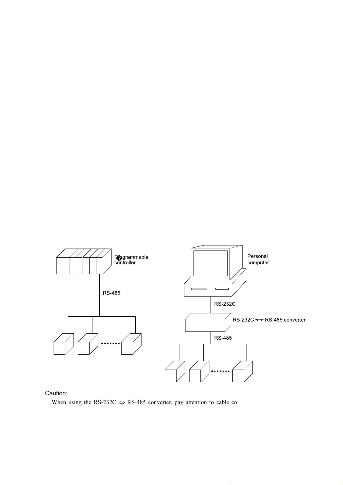
・ PXR provides a communication function by RS-485 interface, by which it can transmit and receive data to and
from host computer, programmable controller, graphic display panel, etc.
・ The communication system consists of master station and slave stations. Up to 31 slave stations (PXR) can be
connected per master station.
Note that, because the master station can communicate with only one slave station at a time, a party to
communicate with must be specified by the "Station No." set at each slave station.
・In order that the master station and slave station can communicate, the format of the transmit/receive data must
coincide. Before using communication function, it is necessary for master station to create a program to operate
data transmit/receive in accordance to Z-ASCII protocol described in this manual.
・Please use on RS-232C ⇔ RS-485 converter in case of designating a personal computer or other devices which
have an RS-232C interface as a master station.
[RS-232C ⇔ RS-485 converter] (recommended article)
Type: KS-485 (non-isolated type)/SYSTEM SACOM Corp.
Type: SI-30A (isolated type)/SEKISUI ELECTRONICS Co., Ltd.
Caution:
When using the RS-232C ⇔ RS-485 converter, pay attention to cable connection between the converter and
master station. If the cable is not connected correctly, the master station and slave station cannot communicate.
In addition, be careful about communication settings such as baud rate and parity set for the converter.
-1-

2. SPECIFICATIONS
2.1 Communication Specifications
Item Specification
Electrical specification Based on ETA RS-485
Transmission system 2-wire, semi-duplicate
Synchronizing system Start-stop synchronous system
Connection format 1:N
Number connectable units Up to 31 units
Transmission distance 500m max. (total extension distance)
Transmission speed 9600bps
Data format
Transmission code ASCII code
Error detection BCC (Addition)
Isolation Functional isolation between transmission circuit
Data length 8 bits
Stop bit 1 bit
Parity none, even, odd (selectable)
and others (withstand voltage : 500V AC)
-2-
3. CONNECTION
WARNING
For avoiding electric shock and malfunctions, do not turn on the power supply untill all wiring
have been completed.
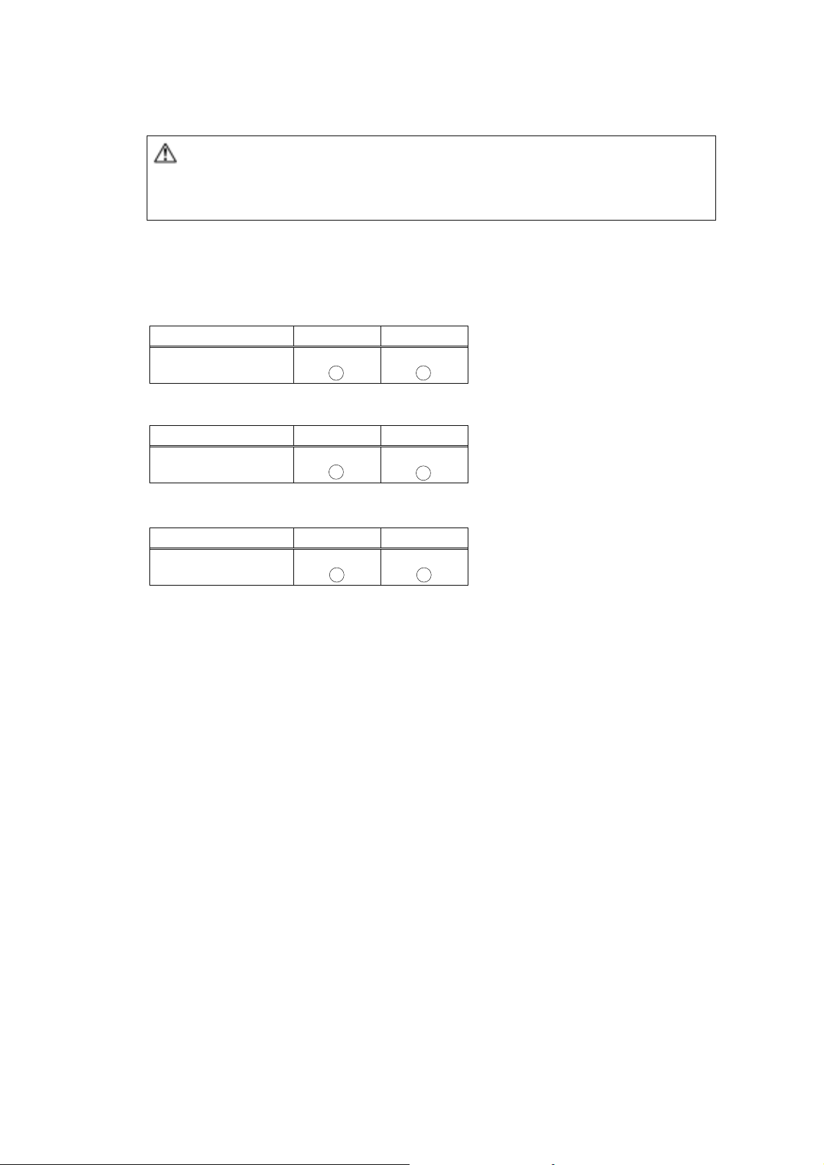
3.1 Communication Terminal Allocation
PXR3
Terminal number
Signal name
PXR4
Terminal number
Signal name
PXR5,PXR9
⑮ ⑭
RS485
+
⑦ ⑧
RS485
+
RS485
-
RS485
-
Terminal number
Signal name
① ②
RS485
+
RS485
-
-3-
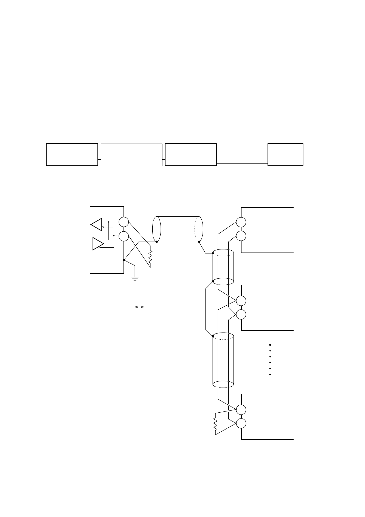
3.2 Wiring
・Use twisted pair cables with shield.
・The total extension length of the cable is up to 500 m. A master station and up to 31 units of the PXR can be
connected per line.
・Both ends of the cable should be terminate with terminating resistors 100Ω 1/2W.
・The shield wire of the cable should be grounded at one place on the master station unit side.
・If the PXR is to be installed where the level of noise applied to the PXR may exceed 1000 V, it is recommended
to install a noise filter in the master station side as below.
Recommended noise filter: ZRAC2203-11/TDK
Master station
(PC, etc.)
RS-232C RS-485
Master station side
Noise filter PXR
Transmission
cable
Slave station (PXR)
Twisted pair cable with shield
+
−
FG
Terminating resistor
100Ω(1/2W)
RS-485 interface
or
RS-485 side of the RS-232C RS-485 converter
+
−
Slave station (PXR)
+
−
Slave station (PXR)
+
−
Terminating resistor
100Ω(1/2W)
-4-

4.
SETTING OF COMMUNICATION CONDITION
In order that the master station and instrument (PXR) can correctly communicate, following settings are required.
・ All communication condition settings of the master station are the same as those of instruments (PXR).
・All instruments (PXR) connected on a line are set to "Station Nos. (STno)" which are different from each other.
(Any "Station No." is not shared by more than one instrument.)
4.1 Set Items
The parameters to be set are shown in the following table. Set them by operating the front panel keys.
Parameter
symbol
―――
―――
―――
CoM Parity setting 0
STno Station No. 1 0 to 255
PCoL
Transmission speed 9600bps Fixed (can not be changed)
Data length 8 bits Fixed (can not be changed)
Stop bit 1 bit Fixed (can not be changed)
Communication
protocol
Item
Value at
delivery
As
specified
in order
Setting range Remarks
0: odd parity
1: even parity
2: none parity
0: Z-ASCII
1: Modbus
Set the same
communication
condition to the master
station and all slave
stations.
Set a different value to
each station.
Set the parameter to “0”.
(The parameter is not
displayed depending on
models).
-5-
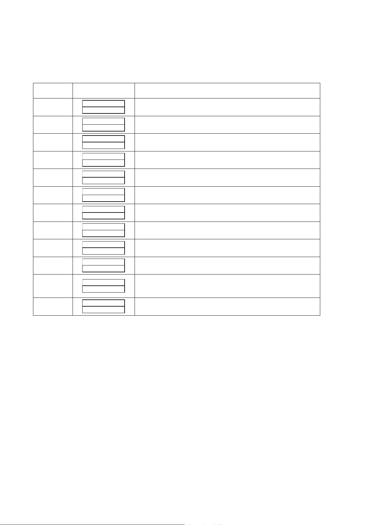
4.2 Setting Operation Method
The following example shows how to set the communication conditions.
Example: Selecting an even parity and “STno=18” on a station.
Key
operation
SEL
(6 seconds)
∨
SEL
∧∨
SEL
∨
SEL
∧∨
SEL
∨
SEL
(3 seconds)
Indication Description
200
200
P-n1
STno
STno
STno
18
STno
18
CoM
CoM
CoM
CoM
PCoL
200
200
Running state (PV/SV indication)
Press the SEL key for approximately 6 seconds. P-n1 appears and
0
No. 3 block parameter is selected.
Operate the ∨ key repeatedly until STno parameter appears. (If past
0
over, operate the ∧ key to return.)
Press the SEL key. The numeric value on the lower indicator
0
blinks and the setting mode is selected.
Operate the ∧ or ∨ key to change the numeric value to 18.
Press the SEL key again. The numeric value stops blinking and
the setting is registered.
Press the ∨ key to display the CoM parameter.
0
Press the SEL key. The numeric value on the lower indicator
0
blinks and the setting mode is selected.
Operate the ∧ or ∨ key until the numeric value changes to 1 (even
1
parity).
Press the SEL key again. The numeric value stops blinking and
1
the setting is registered.
Press the ∨ key to display the PCoL parameter.
Make sure that the set value is set to “0”.
0
Press the SEL key for 3 seconds to resume the running indication
(PV/SV indication).
(If the set value is set to another one, set it to “0”).
-6-
5.1 General
Transmission procedures according to the Z-ASCII protocol is as shown below
1) The master station sends a command frame in a pre-determined format to a slave station.
2) The slave station checks if the station No. in the received frame matches with the own station No. or not.
3) If matched, the slave station executes the command and sends back the result in a pre-determined format.
4) If mismatched, the slave station stops receiving the command frame and wait for the next command
frame.
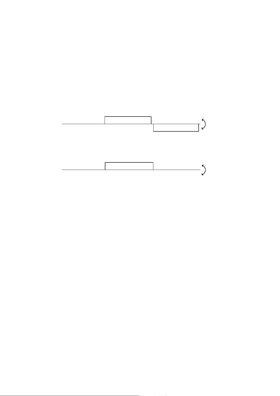
a) In case when the station No. in the received command frame matches with the own slave station No.
5. Z-ASCII PROTOCOL
Master to slave
Slave to master
b) In case when the station No. in the received command message mismatches with the own slave station
No.
Master to slave
Slave to master
The master station can individually communicate with any one of slave stations connected on the same line
upon setting the station No. in the command message.
Command frame
Command frame
Response frame
(Not respond)
Data on
the line
Data on
the line
-7-

5.2 Composition of the Command Frame
The communication frames (Command Frame & Response Frame) consist of the following 6 fields, and these 6
fields are always sent in order.
①③ ⑤⑥
ead code Station No. Command code Parameter End code BCC
The details of each fields are as described in the foliowings.
②④
Fig. 5-1 Composition of message
(1) Head code [1 digit]
This code means "Head of Frame". One of the following code can be used.
":"(3AH) or STX(02H)
Depending on the code used, the End code automatically selected according to the below shown table.
Head code
End code
Whenever the slave (PXR) receives the Head Code, it starts receiving new command frame.
In other words, the previously received command frame is automatically cancelled even not completed
“:”(3AH) [1 digit] STX(02H) [1 digit]
CR(0DH)+LF(0AH) [2digits] ETX(03H) [1 digit]
Combination 1 Combination 2
-8-

(2) Station No. [3 digits]
This code means the slave station number.
Only one slave, which has same station number as determined at "STno" parameter, accept the command from
the master.
Please refer to chapter 4 for the details of "STno" settings.
Note : This code is always defined with 3 digits.
Please add "0" in front of the station No. in case it is less than 100.
Ex.) Station No. =5 → "STno." Setting = "005"
(3) Command code [2 digits]
By setting this code, commands type to be performed by the slave (PXR) can be determined.
There are two kinds of command, "Read-out" and "Write-in".
For the details, please refer to chapter 6.
(4) Parameter [Number of digit is depending on kind of command]
This is the data which is essential to operate the command.
The kind of necessary data is depending on the each command.
Please refer to chapter 6.
(5) End Code [1 digit or 2digits]
This code means "End of Communication Frame".
Please refer to chapter 5.2(1).
(6) BCC (Block Check Character) [2 digits]
This code is used for detecting errors in data transmission. First of all, each character of station No., command
code, Parameter and End Code are summed.
From last 1 byte of the calculation result, the first character goes to the 1st byte, and the last character goes to the
2nd byte in BCC.
Ex.)
:001RW31001,1CRLF(BCC)
30
H 30H 31H 52H 57H 33H 31H 30H 30H 31H 2CH 31H 0DH 0AH
BCC=30H+30H+31H+52H+57H+33H+31H+30H+30H+31H+2CH+31H+0DH+0AH=02A3H
The last 1 byte
of calculation result : A 3H
The first character “A” : 41H
The last character “3” : 33
H
-9-

5.3 Response of Slave Station
(1) Response for normal command
To a relevant message, the slave station creates and sends back a response frame which corresponds to the
command frame. The composition of frame in this case is the same as in chapter 5.2.
For details, refer to chapter 6.
(2) Response for abnormal command
If there is any abnormality in the contents of a command frame, other than transmission error like parity error
(ex. an indefinite command code), the slave station does not execute that command but creates and sends
back a response frame at error detection.
Head code Station Error code End code BCC
Fig. 5-2 Response frame at error direction
Table 5-1 Error code
Error code Name Meaning
CE Command Error Indefinite command code is used
PE Parameter Error Parameter format/range towards command
code is not correct.
(3) No response
Under any of the following events, the slave station takes no account of the command frame and sends back no
response.
・ A station number transmitted in the command frame differs from the station number specified to the slave
station.
・ Received BCC differs from calculated BCC
・ Any transmission error (parity error, buffer overflow and etc.) is detected.
・ Time distance between the datas in command frame is longer than 1 second.
・ Indefinite combination of Head code and End code is used. (ex. Head code : STX, and End code : CR.LF)
-10-

5.4 Transmission Control Procedure
(1) Transmission procedure of master station
The master station must proceed to a communication upon conforming to the following items.
(1-1) Before sending a command frame, provide 5 ms or more vacant status.
(1-2) For sending, the interval between bytes of a command message is below 1 second.
(1-3) Within 15 ms after sending a command message, the receiving status is posted.
(1-4) Provide 5 ms or more vacant status between the end of response frame reception and beginning of
next command frame sending [same as in (1-1)].
(1-5) For ensuring the safety, make a confirmation of the response frame and make an arrangement so as
to provide 3 or more retries in case of no response, error occurrence, etc.
Note) The above definition is for most unfavorable value. For ensuring the safety, it’s recommended the
program of the master to work with safety factors of 2 to 3. Concretely, it is advised to arrange the
program with 10 ms or more for vacant status (1-1), and within 10 ms for byte interval (1-2) and
changeover from sending to receiving (1-3).
Waiting time of master station : min.5ms
necessary (Recommended to have 10 ms or longer
Command
frame
Data processing
of master station
Data
transmission
Signal status on
communication
Command
frame
Response
frame
Response time of slave ; 15 to 50 ms
More than 1 sec.
No response
-11-

5.5 Precautions when Writing Data
PXR contains internal nonvolatile memory (EEPROM) that is used to save the setting parameters. The data
written to the nonvolatile memory (EEPROM) remains even after the power for PXR is turned off. Parameters
that are written via communication are automatically saved in the internal nonvolatile memory (EEPROM).
However, please note that there are two limitations as follows.
Caution:
1. There is a limit to the number of times that data can be transferred to the nonvolatile memory (EEPROM)
(100,000 times). Data cannot be guaranteed if written more than 100,000 times.
Be careful not to transfer unnecessary data when writing data via communication.
In particular, when constructing a communication system with master POD (such as a touch panel), make
sure that the POD writing and trigger settings are appropriate.
Avoid writing at fixed cycles.
Writing to the nonvolatile memory (EEPROM) takes several milliseconds. If the power for PXR is turned
2.
off during this operation, the data saved to the nonvolatile memory (EEPROM) may be corrupted.
Wait several seconds after writing data before turning off the power.
In particular, when writing data in a cycle from master device, there is a greater danger of the writing timing
and power shutoff timing coinciding.
Avoid writing at fixed cycles.
-12-

6.
DETAILS OF COMMAND AND RESPONSE FRAMES
6.1 Data Read-out
(1) Command Frame
① ②
RW
code
Station No. Parameter BCCHead
① Command Code
“RW” : Command to start "Read-out"
② Parameters
(a) Register No. : Defines data register No. 5 digits to be Read-out
(b) Partition character " , " : Always added after Register No.
(c) Read-out No. : Defines number of continuous data starting from the register No. defined in
(2) Response Frame
Command
code
(a) (b)
(Register No.)
ASCII code : [52H, 57H]
(ASCII code : [2C
])
H
above (c). (Max data No. is 4.)
Read-out No.: (c)
,
End
code
! "
# $ "
# % ! $&
("
'"
②
"
S
① Response Code
“RS” : Defines that Read-out procedure was performed successfully.
ASCII code : [52
, 53H]
H
-13-

② Parameters
(a)Data codes : Always in 5 digits
(Sign part : 1 digit + Numeral part : 4 digits)
·Sign part :
Data value Character ASCII code
Minus
"-"
2DH
Plus or 0 "0" 30H
·Numeral part : Always in 4 digits
Ex. 1234→1234
123→0123
12→0012
1→0001
(b)Partition character " , " : In case number of data (s) is more than 2, this character is put between data
codes. ASCII code : [2C
]
H
(c)(Repeat) : In case number of data (s) to be read-out is more than 2, this part is added.
-14-

A
e
[Example of data read-out command]
To read-out 4 continuous data parameters starting from register No. 31001 (station No. =125)
→PV, SV, DV and MV data will be read out
<Condition> Decimal point position = 1 (parameter P-dP = 1)
Command Frame
y
:125RW31001,4CRLFAD
3AH 31H 32H 35H 52H 57H 33H 31H 30H 30H 31H 2CH 34H ODHOAH 41H 44H
←Character
←
SCII cod
y
Response Frame
:125RS02455,0300 0 ,
H31H32H35H52H53H30H32H34H35H35H2CH30H33H30H30H30H2CH
3A
-0545,01030CRLFBA
<
H30H35H34H35H2CH30H31H30H33H30HODHOAH42H41H
2D
>
y
Read-out Result
Register No. Meaning
Read-out data
Sign part Numeral
Values (Note *1)
→
part
31001 PV 0 2455 245.5
31002 SV 0 3000 300.0
31003 DV
-
31004 MV 0 1030
0545 -54.5
103.0
(Note *l) Data in Register No. 31004 is always defined to have decimal point position as shown below.
For the other datas, the decimal point position is depending on PXR parameter setting at "P-dP".
(See chapter 7.1.1 for the details.)
-15-

6.2 Data Write-in
(1) Command Frame
Head code Station No. Parameters End code BCC
① Command Code
“WW” : Command to start "Write-in"
② Parameters
(a) Register No. : Defines data register No. to be read-out.
(b) Partition character " , " : Always added after Register No.
(c) Data codes : Always in 5 digits
·Sign part :
Command
① ② (a) (b) (c)
WW
code
ASCII code : [57
(Register No.)
H
, 57H]
(Data code:Always
,
in 5 digits)
Please refer to chapter 7. for details of parameter, Register No.
ASCII code : [2C
H
]
(Sign part:1digit + Numeral part:4 digits)
Data value Character ASCII code
Minus
"-"
Plus or 0 "0" 30H
·Numeral part : Always in 4 digits
Ex. 1234→1234
123→0123
12→0012
1→0001
(2) Response Frame
①
WS
Head
code
Station No. End code BCC
① Response code
“WS” : Defines that write-in procedure was performed successfully.
Response
code
ASCII code : [57
, 53H]
H
2DH
Caution When setting is being locked, response is returned normally. However, the
command is not executed. If the write-in command message is sent to any slave
station during the FIX process, response is not returned from it.
-16-

[Example of data Write-in command]
To write-in "85" into registered No.41032 (Upper limit of set value).
(station No. =15)
<Condition> Decimal point position = 0 (parameter P-dP = 0)
Command Frame
y
Sign part: ]0^ (value more than 0)
]85^: 0085 (high order 0 added)
:015WW41032, 0 0085CRLF7E
3AH30H31H35H57H57H34H31H30H33H32H2CH30H30H30H38H35HODHOAH37H45
H
Response Frame
y
:015WSCRLF57
H30H31H35H57H53HODHOAH35H37H
3A
-17-

7. ADRESS MAP AND DATA FORMAT
7.1 Data Format
7.1.1 Transmission data format
With this protocol, all data is sent/received in ASCII codes.
7.1.2 Handling of decimal point
Transmission data has no decimal point, so, it is necessary for the master station to perform the following treatment.
(1) Delete decimal point(s) from data to be transmit.
(2) Add decimal point(s) to data received.
Please refer to the following table for the details.
Table 7-1 List of datas which require treatment of decimal point
Digit No. after decimal
point
0, 1 or 2 digit(s) PXR
parameter
1 digit
[Ex. 1] Read-out result from resister No. 31001 (process value : PV) is "300".
(1) In case of P-dP=0 (No. decimal point defined)
Actual SV=300
(2) In case of P-dP=l (decimal point setting )
Actual SV=30.0
Parameter [ P-SL ] 41018
Parameter [ P-SU ] 41019
Datas dependent on input range See address map (Chapter 7.2)
Parameter [ P ]
Parameter [ d ]
Parameter [ CooL ]
Parameter [ dB ]
Parameter [ bAL ]
Parameter [ P-dF ]
Parameter [ PLC1 ]
Parameter [ PHC1 ]
Parameter [ PLC2 ]
Parameter [ PHC2 ]
Parameter [ HB ]
Parameter [ Ao-L ]
Parameter [ Ao-H ]
Parameter [ r-dF ]
Parameter [ OUT1 ]
Parameter [ OUT2 ]
Parameter [ CT ]
Kind of data Register No.
41006
41008
41010
41011
41013
41022
41025
41026
41027
41028
41039
40115
40116
40120
31004
31005
31010
[Ex. 2] Write-in "46" to register No. 41003 (set value : SV)
(1) In case of P-dP=0
Write-in value=46
(2) In case of P-dP=l
Write-in value=460
[Note: Actual transmission data is "00046".]
-18-

7.1.3 Data status during abnormal data input indication
When "UUUU" or "LLLL" is displayed on the face panel on account of over-range, under-range or input
open circuit for example, PV read-out value is 105% or -5% of input range.
Presence of any input abnormality via communication can be detected by:
"Register No. 31008: Input/main unit abnormal status"
7.1.4 Range of write-in data
When data is written in each parameter, the write-in data should be kept within the setting range. PXR accepts
the write-in data beyond the range. However, be careful since the PXR performance will not be guaranteed.
7.2 Data Address Map
For details about individual parameter functions or setting ranges, please refer to the Operation Manual
(ECNO: 406).
Word data [read-out/write-in]:
Register
No.
41001 Word
41002 Word PID/FUZZY/SELF selection
41003 Word SV value set on face panel -1999 to 9999 (within set value limits)
41004 Word Control RUN/standby
41005 Word Auto tuning command
41006 Word P
41007 Word I
41008 Word D
41009 Word
41010 Word COOL
41011 Word Dead band
41012 Word Anti-reset windup -1999 to 9999 (0 to 100% value of input scale)
41013 Word Output convergence value
41014 Word PV shift
41015 Word SV offset
41016 Word Input type code 0 to 16
41017 Word Temperature unit 0:ºC 1:°F
41018 Word Input scale lower limit -1999 to 9999
41019 Word Input scale upper limit -1999 to 9999
41020 Word Decimal point place 0 to 2
Type Memory contents Read-out data
Non-volatile memory write-in
(FIX execution)
Hysteresis range at
two-position control
0: Not writing-in
1: Writing in memory
0: PID control
1: FUZZYcontrol
2: SELF tuning control
0: Invalidate standby (RUN)
1: Validate standby
0: Auto tuning
disabled
1: While executing
standard type AT
executed
2: While executing
low PV type AT
executed
0 to 9999(0.0 to 999.9%)
0 to 3200(0 to 3200 sec)
0 to 9999(0.0 to 999.9 sec)
0 to 9999(0 to 50% value of input scale) *
0 to 1000(0.0 to 100.0)
-500 to 500(-50.0 to +50.0%)
-1000 to 1000
(-100.0 to 100.0%)
-1999 to 9999
(-10 to 10% value of input scale)
-1999 to 9999
(-50 to 50% value of input scale)
Write-in data
setting range
0: No request
1: Request to write in
0: Disable auto
tuning
1: Request
execution of
standard type
2: Request
execution of low
PV type AT
Affected by
input range
*
*
*
*
Remarks or
corresponding
parameter
(Same function
as 00001)
CTrL
* Inhibit
change while
controlling
STby
AT
P
i
D
HyS
CooL
db
Ar
bAL
PVOF
SVOF
P-n2
P-F
P-SL
P-SU
P-dP
-19-

Register
No.
41021 Word (Do not use)
41022 Word Input filter time constant
41023 Word RCJ yes/no
41024 Word MV limit kind 0 to 15
41025 Word Output 1 lower limit
41026 Word Output 1 upper limit
41027 Word Output 2 lower limit
41028 Word Output 2 upper limit
41029 (Do not use)
41030 (Do not use)
41031 Word Set value (SV) lower limit
41032 Word Set value (SV) upper limit
41033 (Do not use)
41034 (Do not use)
41035 (Do not use)
41036 (Do not use)
41037 (Do not use)
41038 (Do not use)
41039 Word Heater burnout alarm set value
41040 Word Setting lock 0 to 5
41041 Word Alarm 1 type 0 to 34
41042 Word Alarm 2 type 0 to 34
41043 Word Alarm 3 type 0 to 34
41044 Word
41045 Word
41046 Word
41047 Word Alarm 1 upper limit set value
41048 Word Alarm 2 upper limit set value
41049 Word Alarm 3 upper limit set value
41050 Word Alarm 1 hysteresis
41051 Word Alarm 2 hysteresis
41052 Word Alarm 3 hysteresis
41053 Word Alarm 1 ON-delay set value
41054 Word Alarm 2 ON-delay set value
41055 Word Alarm 3 ON-delay set value
41056 (Do not use)
41057 Word Ramp/soak No. 1 target value
41058 Word Ramp/soak No. 2 target value
41059 Word Ramp/soak No. 3 target value
41060 Word Ramp/soak No. 4 target value
41061 Word Ramp/soak No. 5 target value
41062 Word Ramp/soak No. 6 target value
41063 Word Ramp/soak No. 7 target value
41064 Word Ramp/soak No. 8 target value
Type Memory contents Read-out data
Alarm 1 set value or
alarm 1 lower limit set value
Alarm 2 set value or
alarm 2 lower limit set value
Alarm 3 set value or
alarm 3 lower limit set value
Write-in data
setting range
0 to 9000(0.0 to 900.0 sec)
0: Disable RCJ compensation
(do not perform reference cold junction
compensation)
1: Enable RCJ compensation (perform
reference cold junction compensation)
-30 to 1030(-3.0 to 103.0%)
-30 to 1030(-3.0 to 103.0%)
-30 to 1030(-3.0 to 103.0%)
-30 to 1030(-3.0 to 103.0%)
-1999 to 9999(within input scale) *
-1999 to 9999(within input scale) *
0 to 500(0.0 to 50.0A)
-1999 to 9999
For absolute value alarm
0 to 100% value of input scale
For deviation alarm
-100 to 100% value of input scale
-1999 to 9999
For absolute value alarm
0 to 100% value of input scale
For deviation alarm
-100 to 100% value of input scale
0 to 9999
(0 to 50% value of input scale)
0 to 9999(0 to 9999 sec)
-1999 to 9999
(within set value limit)
Affected by
input range
*
*
*
*
*
*
*
*
*
*
*
*
*
*
*
*
*
Remarks or
corresponding
parameter
P-dF
rCJ
PCUT
PLC1
PHC1
PLC2
PHC2
SV-L
SV-H
Hb
LoC
ALM1
ALM2
ALM3
AL1 or A1-L
AL2 or A2-L
AL3 or A3-L
A1-H
A2-H
A3-H
A1hy
A2hy
A3hy
dLy1
dLy2
dLy3
Sv-1
Sv-2
Sv-3
Sv-4
Sv-5
Sv-6
Sv-7
Sv-8
-20-

Register
No.
41065 Word Ramp/soak No. 1 ramp time
41066 Word Ramp/soak No. 1 soak time
41067 Word Ramp/soak No. 2 ramp time
41068 Word Ramp/soak No. 2 soak time
41069 Word Ramp/soak No. 3 ramp time
41070 Word Ramp/soak No. 3 soak time
41071 Word Ramp/soak No. 4 ramp time
41072 Word Ramp/soak No. 4 soak time
41073 Word Ramp/soak No. 5 ramp time
41074 Word Ramp/soak No. 5 soak time
41075 Word Ramp/soak No. 6 ramp time
41076 Word Ramp/soak No. 6 soak time
41077 Word Ramp/soak No. 7 ramp time
41078 Word Ramp/soak No. 7 soak time
41079 Word Ramp/soak No. 8 ramp time
41080 Word Ramp/soak No. 8 soak time
41081 Word Ramp/soak mode 0 to 15
41082 Word Ramp/soak command
Note
41083 Word Ramp/soak execution mode
41084
41085 Word PV stable range -1999 to 9999 (within input scale)
41086 (Do not use)
41087 Word
41088 Word Control action type code 0 to 19
41089 Word
41090 Word
41091 Word (Do not use)
41092 Word Alarm 1 option function
41093 Word Alarm 2 option function
41094 Word Alarm 3 option function
41095 Word DI1 action setting
41096 Word DI2 action setting
41097 Word Hysteresis mode setting
41098 Word (Do not use)
41099 Word User zero adjustment
41100 Word User span adjustment
41101 Word
41102 Word
41103 Word
41104 Word
Type Memory contents Read-out data
0 to 5999(0 to 5999 min)
* With main unit parameter,
Min
Hour
is displayed and set.
Therefore, correspondence occurs as:
3601: Data via communication
∥
6001: Display/setting on main unit
0: oFF
Ramp/soak stopped
1: rUn
Ramp/soak operated
2: HLd
Ramp/soak halted
3: End
Ramp/soak ended
0: Execute No. 1 to 4 ramp/soak
1: Execute No. 5 to 8 ramp/soak
2: Execute No. 1 to 8 ramp/soak
(Do not use)
Communication DI action
request
Output proportional cycle
(output 1)
Output proportional cycle
(output 2)
DSP1
(parameter mask designation)
DSP2
(parameter mask designation)
DSP3
(parameter mask designation)
DSP4
(parameter mask designation)
*② (refer to section 7.3.)
0: Current output type
1 to 150(1 to 150 sec):
Relay, SSR drive output type
1 to 150(1 to 150 sec)
0 to 7(binary data 000B to 111B)
0 to 12
0: off (main unit parameter setting)
1: on (main unit parameter setting)
-1999 to 9999
(-50 to 50% value of input scale)
-1999 to 9999
(-50 to 50% value of input scale)
0 to 255
0 to 255
0 to 255
0 to 255
Write-in data
setting range
0: oFF
Stop ramp/soak
1: rUn
Start ramp/soak
2: HLd
Halt ramp/soak
Affected by
input range
*
*
*
Remarks or
corresponding
parameter
TM1r
TM1S
TM2r
TM2S
TM3r
TM3S
TM4r
TM4S
TM5r
TM5S
TM6r
TM6S
TM7r
TM7S
TM8r
TM8S
MOD
ProG
PTn
SLFb
P-n1
TC
TC2
A1op
A2op
A3op
di-1
di-2
ONOF
ADJ0
ADJS
dSP1
dSP2
dSP3
dSP4
-21-

Register
Type Memory contents Read-out data
No.
41105 Word
41106 Word
41107 Word
41108 Word
41109 Word
41110 Word
41111 Word
41112 Word
41113 Word
41114
Word
41115
Word
41116
Word
41117
Word
41118
Word
41119
Word
41120
Word
DSP5
(parameter mask designation)
DSP6
(parameter mask designation)
DSP7
(parameter mask designation)
DSP8
(parameter mask designation)
DSP9
(parameter mask designation)
DSP10
(parameter mask designation)
DSP11
(parameter mask designation)
DSP12
(parameter mask designation)
DSP13
(parameter mask designation)
Type of Re-transmission output
Re-transmission output scaling
lower limit
Re-transmission output scaling
upper limit
Local/remote operation
changeover
Remote SV input zero
adjustment
Remote SV input span
adjustment
Remote SV input filter time
constant
Write-in data
setting range
0 to 255
0 to 255
0 to 255
0 to 255
0 to 255
0 to 255
0 to 255
0 to 255
0 to 255
0:PV,1:SV,2:MV,3:DV
-10000 to 10000
(-100.00 to 100.00%)
-10000 to 10000
(-100.00 to 100.00%)
0: Local
1: Remote
-1999 to 1999
(-50 to 50% of input scale)
-1999 to 1999
(-50 to 50% of input scale)
0 to 9000 (0.0 to 900.0 sec)
Affected by
input range
*
*
Remarks or
corresponding
parameter
dSP5
dSP6
dSP7
dSP8
dSP9
dSP10
dSP11
dSP12
dSP13
Ao-T
Ao-L
Ao-H
CMod
rEM0
rEMS
r-dF
Note) Read-out/write-in data from resister No. 41083 (ramp/soak mode selection) correspond to parameter "PTn"
to be displayed as shown below:
Read-out/write-in data Parameter PTn Ramp/soak execution mode
0 1 1 to 4 ramp/soak executed
1 2 5 to 8 ramp/soak executed
2 3 1 to 8 ramp/soak executed
Word data (read-out only) :
Register
No.
31001 Word Process value (PV) -1999 to 9999 (within input scale)
31002 Word Currently used set value (SV) -1999 to 9999 (within set value limit)
31003 Word Currently used deviation (DV)
31004 Word MV (output 1)
31005 Word MV (output 2)
31006 Word Station No. 0 to 255
31007 Word Alarm status
31008 Word Input/main unit abnormal status
31009 Word
31010 Word Heater current
31011 Word Timer 1 current count
31012 Word Timer 2 current count
31013 Word Timer 3 current count
31014 (Reserve)
31015 Word DI action status
31037 Word Remote SV input value -1999 to 9999
Type Memory contents Read-out data
-1999 to 9999
(-100 to 100% value of input scale)
-30 to 1030(-3.0 to 103.0%)
-30 to 1030(-3.0 to 103.0%)
*③ (refer to Section 7.3.)
*④ (refer to Section 7.3.)
Ramp/soak current running
Position
0 to 17
*⑥ (refer to Section 7.3.)
0 to 500(0.0 to 50.0A)
0 to 9999(0 to 9999 sec)
0 to 9999(0 to 9999 sec)
0 to 9999(0 to 9999 sec)
*⑤ (refer to Section 7.3.)
Affected by
input range
*
*
*
*
Remarks or
corresponding
parameter
(Displayed PV)
(Displayed SV)
OUT1
OUT2
STno
STAT
CT
TM-1
TM-2
TM-3
rSV
-22-

Notes)
・ For details of * ② to * ⑥ in the table, refer to Section 7.3.
・ The area marked (Do not use) is a reserve area. Do not write in there.
・ Register numbers 31002 (currently used SV) and 41003 (face panel set SV) do not become the same
value while switching-SV is active or ramp/soak is under way. (Example: While SV-1 is selected, the
value of SV-1 is read out of register number 31002.) For reading out SV for monitoring, use SV in
register number 31002.
7.3 Additional Explanation of Address Map
Datas in the ② to ⑤ are Numerous Value calculated from corresponding bit data.
Therefore, calculation from value to bit data or is based on the following calculation formura.
(1) Write-in data
Add the all bit values corresponding to bits to be written-in as "1" according to the Bit value table (7-2).
Ex.) How to write-inbit 0, 5 and 9 as "1"
Write-in data = 1 (bit 0) +32 (bit 5) +512 (bit 9)=555
(2) Read-out data
Execute AND logic calculation of Read-out data and the bit value of bit which you would like to know the status.
Ex.) How to take out bit 8 and 9 when Read-out data is 324.
Read-out data = 324 = 0000101000100B
Bit value of 8 and 9 = 256+512 = 768 =
Result of AND 256 =
= Bit value 8, then only bit 8 = “1”
Table 7-2 Bit value
Bit Bit weight (additional value)
0 1
1 2
2 4
3 8
4 16
5 32
6 64
7 128
8 256
9 512
10 1024
11 2048
12 4096
-23-

*② Register number 41087 (read-out/write-in area)
Contents of the communication DI action
Used for requesting a DI action via communication. Once written in, the contents remain held unless
the power is turned off or another value is written in. Pay attention to this point particularly when
canceling the alarm latching.
Read-out data is the data which was written in via communication and is different from hardware DI
action request data (see * ⑤). Do not doubly request the action of the same function as hardware DI.
Bit Contents Read-out Write-in
0 1 Switching-SV
selection
Bit 1 0 Bit 1 0
0 0 While selecting
face panel set
0 0 While selecting
face panel set SV
SV
0 1 While selecting
SV-1
0 1 While selecting
SV-1
2 (Reserve)
3 (Reserve)
4 (Reserve)
5 Canceling the alarm 1
latching
6 Canceling the alarm 2
latching
7 Canceling the alarm 3
latching
0: Not requested to cancel the
latching
1: Requested to cancel the latching
0: Not requested to cancel the
latching
1: Requested to cancel the latching
8 ALM1 relay timer
action
9 ALM2 relay timer
action
ALM3 relay timer
10
0: Timer DI = OFF
1: Timer DI = ON
0: Timer DI = OFF
1: Timer DI = ON
action
11 to 15 (Reserve)
*③ Register numbers 31007 (read-out only area)
Alarm status contents
Bit Contents Read-out
0 Alarm 1 output
(calculation result of de-energizing alarm)
1 Alarm 2 output
(calculation result of de-energizing alarm)
2 Alarm 3 output
(calculation result of de-energizing alarm)
0: Alarm 1 relay output OFF
1: Alarm 1 relay output ON
0: Alarm 2 relay output OFF
1: Alarm 2 relay output ON
0: Alarm 3 relay output OFF
1: Alarm 3 relay output ON
3 HB alarm relay output 0: HB alarm output OFF
1: HB alarm output ON
4 Alarm 1 ON/OFF
5 Alarm 2 ON/OFF
6 Alarm 3 ON/OFF
0: Alarm 1 OFF,1: Alarm 1 ON
0: Alarm 2 OFF,1: Alarm 2 ON
0: Alarm 3 OFF,1: Alarm 3 ON
7 HB alarm relay output 0: HB alarm output OFF
1: HB alarm output ON
8 to 12 (Reserve)
-24-

B
*④ Register numbers 31008 (read-out only area)
Input/main unit abnormal status
Bit Contents Read-out
0 Input Lower open-circuit 0: Lower open-circuit absent
1: Lower open -circuit present
1 Input Upper open-circuit 0: Lower open-circuit absent
1: Lower open -circuit present
2 Input under-range 0: Under-range absent
1: Under-range present
3 Input over-range 0: Over-range absent
1: Over-range present
4 (Reserve)
5 (Reserve)
6 Setting range error 0: Setting range normal
1: Setting range abnormal
7 EEPROM error 0: EEPROM normal
1: EEPROM abnormal
8 to 12 (Reserve)
*⑤ Register numbers 310105 (read-out only area)
Contents of DI action status
Hardware DI (DI input terminal) action request information
Bit Contents Read-out
0 1 Switching-SV selection
2 Control RUN/standby 0: Control RUN requested
3 Auto tuning (standard) 0: AT not requested
4 Auto tuning (low PV type) 0: AT not requested
5 Canceling the alarm 1 latching
6 Canceling the alarm 2 latching
7 Canceling the alarm 3 latching
8 ALM1 relay timer action
9 ALM2 relay timer action
10 ALM3 relay timer action
11 RUN/RESET selection of
ramp/soak
12 to 15 (Reserve)
it 1 0
0 0 Face panel set SV selected
0 1 SV-1 selected
1: Control standby requested
1: AT (standard) action requested
1: AT (low PV type) action requested
0: Not requested to cancel the latching
1: Requested to cancel the latching
0: Timer DI = OFF
1: Timer DI = ON
0: Not requested RUN (RESET)
1: Requested RUN
-25-

*⑥ Register numbers 31009 (read-out only area)
Ramp/soak current tuning position
Read-out
data
Indication of parameter
“STAT”
0 oFF Stop status of ramp/soak
1 1-rP No.1 ramp time
2 1-Sk No.1 soak time
3 2-rP No.2 ramp time
4 2-Sk No.2 soak time
5 3-rP No.3 ramp time
6 3-Sk No.3 soak time
7 4-rP No.4 ramp time
8 4-Sk No.4 soak time
9 5-rP No.5 ramp time
10 5-Sk No.5 soak time
11 6-rP No.6 ramp time
12 6-Sk No.6 soak time
13 7-rP No.7 ramp time
14 7-Sk No.7 soak time
15 8-rP No.8 ramp time
16 8-Sk No.8 soak time
17 End End status of ramp/soak
Running position (status)
-26-

8. SAMPLE PROGRAM
This section concerns data read-out/write-in sample program by GW-BASIC*1 which operated on Windows 95*1
1
MS-DOS*
Note that the program shown here is for reference for you to create a program and not for guaranteeing all actions.
Before executing the program, make sure of the communication conditions in the following procedure.
・Communication speed (baud rate), data length, stop bits and parity bit
Set in this program. Match the conditions with this instrument.
Note) Cautions on using SEKISUI's RS232C and RS485 converter unit (SI-30A)
*1: GW-BASIC, Windows 95 and MS-DOS are registered trademarks of Microsoft Corporation.
PROMPT.
In SI-30A, send data are received, added to start of the answer data from the slave station. After
cleared data corresponding to the number of sending bytes, treat the remaining data as the answer data
in the data receiving process.
-27-

(a) Example of data read-out
How to Read-out PV, SV (currently used), DV, MV (control output 1) in one time. (From Read-only
memory)
Head code : ”:”
Read-out start No. : 1
Command code : RW
Read-out resister No. : 31001
Number of read out data : 4
End code : CR, LF
1000 '------------------------------------------------------1010 ' READ DATA SAMPLE PROGRAM
1020 '------------------------------------------------------1030 '
1040 '
1050 '
1060 CLS
1100 '-------------- Setting of transmission data ----------------------1110 SCODE$ =":"
1120 STN$ ="001"
1130 CMMD$ ="RW"
1140 REGS ="31001"
1150 RDNUMS =",4"
1160 ECODES =CHR$(&H0D)+CHR$(&H0A)
1200 '
1210 '------------- Creation of Command Frame -------------1215 'BCALC$ =STN$+CMMD$+REG$+RDNUM$+ECODE$
1220 GOSUB 3050 'BCC calculation routine
1230 TXFRM$ =SCODE$+BCALC$+BCC$ 'Transmission Frame
1300 '
1310 '------------- Data transmission----------------------------1320 PRINT "Transmission Frame > ";
1330 OPEN "COM1:9600,o,8,1" AS #1 '9600bps, Odd Parity, Data Length=8, Stop bit=1
1340 PRINT #1,TXFRM$ 'Write-in Comm. port
1350 PRINT TXFRM$ 'Displaying on screen
1360 *BCC is always displayed at the top of next line
1370 after unshown character [CR LF].
1380 '
1390 FOR I=O TO 30000 :NEXT I 'Time interval
1500 '
1510 '------------- Data receive ---------------------------1520 PRINT
1530 RXFRM$=” ”
1540 LENGTH=
1550 IF LENGTH=O THEN PRINT "No answer" :END 'Execution at no response
1560 PRINT "Receive Frame <”;
1570 FOR I=1 TO LENGTH
1580 X$=INPUT$(1,#1) 'Data take-in from Receiving buffer
1590
1600 PRINT X$; 'Displaying on the screen
1610 *BCC is always displayed at the top of next line
1620 after unshown character [CR LF].
1630 NEXT I
1640 CLOSE #1
1700 '
1710 '------------- Check comm. error ----------------------1720 PRINT
1730 RXCMD$=MID$ (RXFRM$,5,2) 'Responce code take-out from receive frame
1740 RXBCC$=RIGHT$ (RXFRM$,2) 'BCC take-out from receive frame
1750 BCALC$=MID$ (RXFRM$,2,LENGTH-3) 'Data take-out for BCC calculation
1760 GOSUB 3050 'BCC calculation routine
1770 IF RXBCC$oBCC$ THEN GOTO 1800 'Comparison BCC take-out data and calc. data
1780 IF RXCMD$o"RS" THEN GOTO 1800 'Judgement of Normal/Abnormal response
1790 GOTO 1920
1800 'ER.MESSAGE
1810 PRINT "Communication error"
1820 END
'Head code
'Station No.
'Command
'Read-out resistor No.
'Partition character "," + Read-out No.
'End code
'Object for BCC calculation
LOC(1) 'Number of data in Receiving buffer
-28-

1900
1910 '------------- Result Display --------------------------1920 PRT.RESULT
1930 In case of decimal point position (P-dP) =1
1940 PRINT
1950 PTR=7 'Data position in receive frame
1960 PV$=MID$(RXFRM$,PTR,5) : PTR=PTR+6 'Take-out lst data
1970 SV$=MID$(RXFRM$,PTR,5) : PTR=PTR+6 'Take-out 2nd data
1980 DV$=MID$(RXFRM$,PTR,5) : PTR=PTR+6 'Take-out 3rd data
1990 MV$=MID$(RXFRM$,PTR,5) 'Take-out 4th data
2000 PRINT "PV =";VAL(PV$)/10; "degree C" '
2010 PRINT "SV =";VAL(SV$)/10; "degree C" '
2020 PRINT "DV =";VAL(DV$)/10; "degree C" '
2030 PRINT "MVl=";VAL(MV$)/10;"%" '
2040 END
3000 '
3010 '------------ BCC calculation routine -----------------------------3020 '
3030 input : BCALCS ・・・ Object characters for BCC calculation
3040 output : BCC$ ・・・ 2 Characters as result of BCC calculation
3050 'BCC.CALC
3060 COUNT=LEN(BCALC$) : SUM=0
3070 FOR J=1 TO COUNT
3080 BYTE$=MID$(BCALC$,J,l) 'Take-out one character from object characters
3090 SUM=SUM+ASC(BYTES) 'Add as ASCII code
3100 NEXT J
3110 BCC=SUM AND &HFF 'Take out the last 1 byte from added result
3120 BCC$=RIGHT$("0"+HEX$(BCC) ,2) 'Transform the Hexadecimal number into 2 characters
3130 RETURN
1 digit after decimal point(depend on P-dp setting)
1 digit after decimal point(depend on P-dp setting)
1 digit after decimal point(depend on P-dp setting)
In case of MV, always 1digit after decimal point
-29-

(b) Example of data write-in
How to set lower limit of input scale as “-10.0”.
(Decimal point position setting, P-dP=1)
Head code : ”:”
Write-in startion No. : 1
Command code : WW
Write-in resister No. : 41018
Number of write-in data : 4
End code : CR, LF
1000 '------------------------------------------------------1010 ' WRITE DATA SAMPLE PROGRAM
1020 '------------------------------------------------------1030 '
1040 '
1050 '
1060 CLS
1100 '-------------- Setting of transmission data ----------------------1110 SCODE$ =":" 'Head code
1120 STN$ ="001" 'Station No.
1130 CMMD$ ="WW" 'Command
1140 REGS ="41018" 'Write-in resistor No.
1150 SP$ ="," 'Partition character ","
1160 SIG$ =”-” 'Sign (minis) *”0” when zero or plus numbers
1170 WRNUM$ =”0100” 'Numeral data *always in 4 digits
1180 ' *Decimal point setting p-dp=l:l digit after decimal point
1190 ' and numeral data is always in 4 digits ・・・・・・ 10.0 -> 0100
1200 'ECODE$ =CHR$(&H0D)+CHR$ (&H0A) 'End code
1250 '
1260 '------------- Creation of Command Frame----------------------------1270 BCALC$ =STN$+CMMD$+REG$+SP$+SIG$+WRNUM$+ECODE$ 'Object for BCC calculation
1280 GOSUB 3050 'BCC calculation routine
1290 TXFRM$ =SCODE$+BCALC$+BCC$ 'Transmission Frame
1300 '
1310 '------------- Data transmission----------------------------1320 PRINT "Transmission Fram > ";
1330 OPEN "COM1:9600,o,8,1" AS #1 '9600bps, Odd Parity, Data Length=8, Stop bit=1
1340 PRINT #1,TXFRM$ 'Write-in Comm. port
1350 PRINT TXFRM$ 'Displaying on screen
1360 *BCC is always displayed at the top of next line
1370 after unshown character [CR LF].
1380 '
1390 FOR I=O TO 30000 :NEXT I 'Time interval
1500 '
1510 '------------- Data receive ---------------------------1520 PRINT
1530 RXFRM$=” ”
1540 LENGTH= LOC(1) 'Number of data in Receiving buffer
1550 IF LENGTH=0 THEN PRINT "No answer" :END 'Execution at no response
1560 PRINT "Receive Frame <”;
1570 FOR I=1 TO LENGTH
1580 X$=INPUT$(1,#1) 'Data take-in from Receiving buffer
1590
1600 PRINT X$; 'Display on the screen
1610 *BCC is always displayed at the top of next line
1620 after unshown character [CR LF].
1630 NEXT I
1640 CLOSE #1
1700 '
1710 '------------- Check comm. error ----------------------1720 PRINT
1730 RXCMD$=MID$ (RXFRM$,5,2) 'Responce code take-out from receive frame
1740 RXBCC$=RIGHT$ (RXFRM$,2) 'BCC take-out from receive frame
1750 BCALC$=MID$ (RXFRM$,2,LENGTH-3) 'Data take-out for BCC calculation
1760 GOSUB 3050 'BCC calculation routine
1770 IF RXBCC$ <> BCC$ THEN GOTO 1800 'Comparison BCC take-out data and calc. data
1780 IF RXCMD$ <> "WS" THEN GOTO 1800 'Judgement of Normal/Abnormal response
1790 GOTO 1920
-30-

1800 'ER.MESSAGE
1810 PRINT "Communication error"
1820 END
1900
1910 '------------- Result Display --------------------------1920 'PRT.RESULT
1930 PRINT
1940 PRINT "Normal response !”
2040 END
3000 '
3010 '------------ BCC calculation routine -----------------------------3020 '
3030 input : BCALCS ・・・・・・ Object characters for BCC calculation
3040 output : BCC$ ・・・・・・ 2 Characters as result of BCC calculation
3050 'BCC.CALC
3060 COUNT=LEN(BCALC$) : SUM=0
3070 FOR J=1 TO COUNT
3080 BYTE$=MID$(BCALC$,J,l) 'Take-out one character from object characters
3090 SUM=SUM+ASC(BYTES) 'Add as ASCII code
3100 NEXT J
3110 BCC=SUM AND &HFF 'Take out the last 1 byte from added result
3120 BCC$=RIGHT$("0"+HEX$(BCC) ,2) 'Transform the Hexadecimal number into 2 characters
3130 RETURN
-31-

9. TROUBLESHOOTING
If the communication is unavailable, check the following items.
□ Whether all devices related to communication are turned on.
□ Whether connections are correct.
□ Whether the number of connected instruments and connection distance are as specified.
□ Whether communication conditions coincide between the master station (host computer) and slave stations
(PXR).
□ Transmission speed : 9600bps
□ Data length : 8 bits
□ Stop bit : 1 bit
□ Parity : □odd
□even
□none
□ Whether send/receive signal timing conforms to Section 5.4 in this manual.
□ Whether the station No. designated as send destination by the master station coincides with the station No. of
the connected PXR.
□ Whether more than one instrument connected on the same transmission line shares the same station No..
□ Whether the station No. of instruments is set at other than 0.
If it is 0, the communication function does not work.
□ Whether the 11th digit of type cord of this controller is N or W?
(PXR4□□□□-□□
N
□□-□)
W
-32-

10. APPENDIX
・ASCII code table
b8
b7
b6
b5
b8 b7 b6 b5 b4 b3 b2 b1
0 0 0 0
0 0 0 1
0 0 1 0
0 0 1 1
0 1 0 0
0 1 0 1
0 1 1 0
0 1 1 1
1 0 0 0
1 0 0 1
1 0 1 0
1 0 1 1
1 1 0 0
1 1 0 1
1 1 1 0
1 1 1 1
Upper
Lower
bits
0
1
2
3
4
5
6
7
8
9
A
B
C
D
E
F
Example:“A”=41H
0 0 0 0 0 0 0 0
0 0 0 0 1 1 1 1
0 0 1 1 0 0 1 1
0 1 0 1 0 1 0 1
bits
0 1 2 3 4 5 6 7
NUL DLE SPACE
SOH DC1
STX DC2
ETX DC3
EOT DC4
ENQ NAK
ACK SYN
BEL ETB
BS CAN
HT EM
LF SUB *
VT ESC
FF FS
CR GS
SO RS
SI US
! 1 A Q a q
“ 2 B R b r
# 3 C S c s
$ 4 D T d t
% 5 E U e u
& 6 F V f v
‘ 7 G W g w
( 8 H X h x
) 9 I Y i y
+ ; K [ k {
, < L \ l ¦
- = M ] m }
. > N ^ n  ̄
/ ? O _ o
0 @ P ‘ p
: J Z j z
DEL
-33-

Head Office
Gate City Ohsaki, East Tower, 11-2, Osaki 1-chome,
Shinagawa-ku, Tokyo 141-0032, Japan
http://www.fesys.co.jp/eng
Instrumentation Div.
International Sales Dept.
No.1, Fuji-machi, Hino-city, Tokyo 191-8502, Japan
Phone: 81-42-585-6201, 6202 Fax: 81-42-585-6187
http://www.fic-net.jp/eng
 Loading...