

Page 1
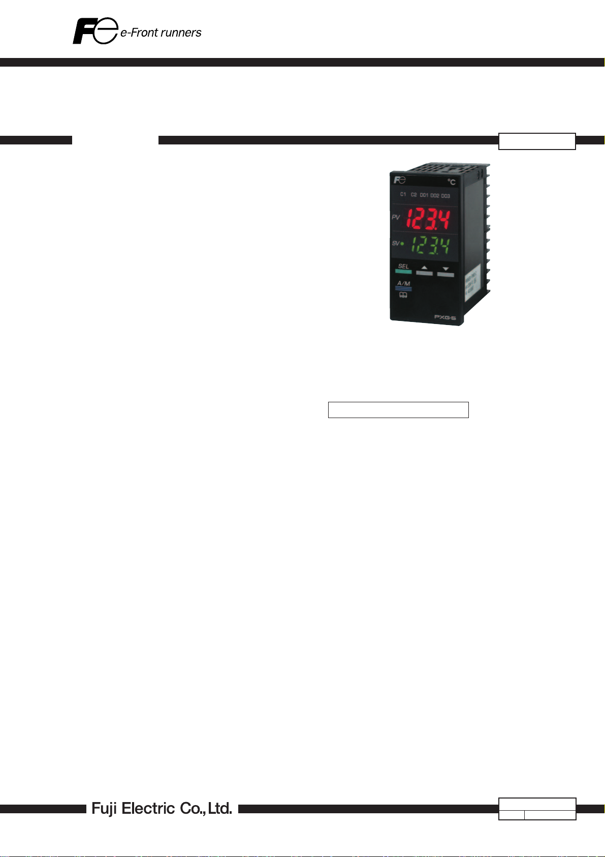
PX series
digital temperature
controller
MICRO-CONTROLLER X (48 × 96 mm)
DATA SHEET
PXG5 is a compact size temperature controller of front panel
size 48 × 96 mm. To cope with any of versatile uses as a
temperature controller, it has many input/output points and
sophisticated control functions.
FEATURES
1. Wide variety and number of input / output
1. Digital input: Up to 5 points
2. Digital output: Up to 5 points
3. Control output: 4 types
Relay contact, SSR drive, voltage linear, current linear
4. Universal inputs: Thermocouple, resistance bulb, current, voltage, mV linear
5. Remote SV input function
6. Analog re-transmission output function (for current or
voltage)
7. Motorized valve control output
2. User interface of easy-to-see indication and easy-to-use
operation method
1. Easy-to-see, large display section
2. Parameters grouped by functions
3. User key to which you can assign a function
4. Password function provided for avoiding wrong operation and protecting settings
5. Front water-proof structure (IP66 in conformity)
3. Advanced control functions to meet various applications
1. Sampling cycle 200 ms (300 ms at position feedback
control)
2. Input indication accuracy ± 0.3%FS
3. Manual control function
4. Control method selectable out of 8 different types:
ON/OFF control, PID control, fuzzy PID control, selftuning control, PID2 control, motorized valve control
(with/without position feedback)
5. Heating/cooling control selectable
6. Auto tuning function
4. A variety of functions extending the possibility of temperature controller
1. Guarantee soak function provided, 16 step ramp/soak
function
2. 8 PID setting pallets, 8 SV pallets capable of frequent
change of control
3. Soft start function that limits MV output when starting up
4. Ramp SV function enables graduate change of SV
5. Loop burnout alarm, heater burnout alarm and different event outputs are available in digital output (option)
6. Control standby function
7. Loader interface (RS232C)
8. RS485 communication (option)
PXG5
SPECIFICATIONS
1. General Specifications
(1) Power supply :
100 V ( - 15%) to 240 V (+ 10%) AC,
50/60 Hz
24 V (± 10%) DC. 24 V (± 10%) AC,
50/60 Hz.
(2) Power consumption:
12 VA MAX.
(3) Insulation resistance:
20 MΩ MIN. (at 500 V DC)
(4) Withstand voltage:
Power source ⇔ all terminals
1500 V AC for 1 min
Relay contact output ⇔ all terminals
1500 V AC for 1 min
Between others 500 V AC for 1 min
(5) Approvals and certification:
UL(UL873), C-UL(CSA C22.2 No.24-93 or
equivalent), CE mark(LVD : EN61010-1,
EMC : EN61326-1)
EDS11-159c
Date
Apr.
1, 2011
Page 2

PXG5
2. Input section
2.1 Process value input
(1) Number of inputs:
1 point
(2) Input setting: Programmable scale
(3) Input signal: See Table 1 (thermocouple, resistance
bulb, mV, voltage, , current(With exter-
nal 250Ω resistance) universal input)
(4) Standard measurement range and input type:
See Table 1
(5) Indication accuracy (at Ta = 23˚C) :
• Thermocouple input: ± 0.3%FS ± 1 digit
± 1˚C or ± 2˚C, whichever greater
*except:
Thermocouple B, 0 to 400˚C
± 5%FS ± 1 digit ± 1˚C
Thermocouple R, 0 to 500˚C
±1%FS ± 1 digit ± 1˚C
Thermocouple T, -200 to 0˚C
±0.5%FS± 1 digit ± 1˚C
• Resistance bulb input: ± 0.3%FS ± 1
digit or ± 0.5˚C, whichever greater
• mV input, voltage input, current input:
± 0.3%FS ± 1 digit
(6) Indication accuracy by change of temperature:
± 0.3%FS/10˚C
(7) Indication resolution:
See Table 1
(8) Input sampling cycle:
200 ms (300 ms at position feedback
control)
(9) Input impedance:
• Thermocouple, mV input: 1 MΩ MIN.
• Current input: 250 Ω
• Voltage input: About 1 MΩ
(10) Variation by signal source resistance:
• Thermocouple, mV input: ± 0.3%FS ±
1 digit per 100 Ω
• Voltage input: ± 0.3%FS ± 1 digit per
500 Ω
(11) Allowable wiring resistance:
• Resistance bulb: 10 Ω MAX. (per wire)
(12) Allowable input voltage:
• DC voltage input: Between +35 and
-10 V
• Current input: Within ± 25 mA
• Thermocouple, resistance bulb, mV in-
put: Within ± 5 V
(13) Noise rejection ratio:
• Normal mode: 40 dB (50/60 Hz)
• Common mode: 120 dB (50/60 Hz)
From ground, at 220 V AC, 50/60 Hz
Between input and output, at 220 V AC,
50/60 Hz
(14) Input correction:
(a) User adjustment: Zero point, span
± 50%FS for each
(b) Process value shift: ± 10%FS
(c) Input filter: 0.0 to 120.0 sec (filter OFF
if set at 0.0)
(15) Overrange, underrange:
Beyond range of -5 to 105% (accuracy
not guaranteed between -5 and 0, and between 100 and 105%FS)
2.2 Auxiliary analog input (remote SV input)
(1) Number of inputs:
Up to 1 point
(2) Input signal: Voltage, 0 to 5 V DC /1 to 5 V DC
(3) Input impedance:
About 1 MΩ
(4)Sampling rate:
800ms (600ms at Position feed back control)
2.3 Heater current detector (CT) input
(1) Input type: Single phase CT Up to 1 point max.
For 1 to 30 A: CTL-6-S-H
For 20 to 50 A: CTL-12-S36-8F
(2) Range of detected current:
1 to 50A
(3) Detected current accuracy:
Setting ± 10%FS
(4) Detected current resolution:
0.1 A
(5) ON time necessary for detection:
800 ms MIN.
2.4 Digital input (DI)
(1) Number of points:
Up to 5 points (up to 3 points for motorized valve control output)
(2) Specifications:No-voltage contact or transistor input
(3) Contact capacity:
30 V DC, about 3 mA (per point)
(4) Input judgment:
ON assumed at 1 kΩ or lower (contact) or
5 V DC or lower (transistor)
OFF assumed at 100 kΩ or higher (con-
tact) or 18 V DC or higher (transistor)
(5) Sampling pulse width:
200 ms MIN. (300 ms MIN. at position
feedback control)
(6) Functions: Remote mode selection, SV changeover,
control standby, AT startup, timer startup,
alarm unlatch, Program selection, start /
stop / reset, PID switching (normal/reverse), etc.
2.5 Valve position feedback signal
(potentiometer) input
(1) Resistance range:
100 Ω to 2.5 kΩ, 3 wire type
(2) Resolution: 0.5%FS
(3) Input accuracy:
± 1.0%FS
(4) Effect of temperture variation:
± 0.5%FS/10˚C
(5) Burnout detection:
none
2
Page 3

3. Output section
3.1 Control output
(1) Number of points:
Up to 2 points (2 points: Heating/cooling
control)
(2) Type: selected out of [1] to [5] below
[1] Relay contact output
• Proportional cycle: 1 to 150 sec
• Contact structure: 1 NO (SPST) contact
• Contact capacity
220 V AC/30 V DC, 3 A (resistive
load)
220 V AC/30 V DC, 1 A (inductive
load)
• Minimum Open/Close current: 100
mA (24 V DC)
• Mechanical life: 20 million operations
MIN. (100 operations/min)
• Electrical life: 100,000 operations
MIN. (rated load)
[2] SSR/SSC drive output
• Proportional cycle: 1 to 150 sec
• ON voltage: 20 V DC (18 to 24 V DC)
• OFF voltage: 0.5 V DC or lower
• Maximum current: 20 mA DC (for
each of outputs 1 and 2)
• Load resistance: 850 Ω MIN.
[3] Current output (0 to 20 mA DC/4 to
20 mA DC)
• Accuracy: ± 5%FS
• Linearity: ± 5%FS
• Load resistance: 600 Ω MAX.
[4] Voltage output (0 to 5 V DC/1 to 5 V
DC/0 to 10 V DC/2 to 10 V DC)
• Accuracy: ± 5%FS
• Linearity: ± 5%FS
• Load resistance: 10 kΩ MIN.
[5] Motorized valve control output
• Contact structure: 2 NO (SPST) contacts
• Contact capacity: 220 V AC/30 V DC,
1 A
• Minimum ON/OFF current: 100 mA
(24 V DC)
• Mechanical life: 20 million operations
MIN. (100 operations/min)
• Electrical life: 100,000 operations
MIN. (rated load)
•Output interlock: Output interlock
circuit provided
3.2 Digital output (DO)
(1) Number of outputs:
Relay contact output
Up to 3 points (shared common)
Up to 2 points (independent common)
Transistor output
Up to 2 points
(2) Output specifications:
(1) Relay contact output
Contact structure: 1 NO (SPST) contact
Contact capacity: 220 V AC/30 V DC,
1 A
Minimum ON/OFF current: 100 mA
(24 V DC)
Mechanical life: 20 million operations
MIN. (100 operations/min)
Electrical life: 100,000 operations MIN.
(rated load)
(2) Transitor output
Contact type: Open collector
Rated values: 30 V DC, 100 mA
ON voltage: 1V or lower
(3) Output functions:
Alarm output (see "Alarm function")
Main unit control mode output, program
status output, etc.
(4) Output cycle: 200ms (300ms at Position feedback con-
trol)
3.3 Auxiliary analog output (re-transmission output)
(1) Number of points: 1 point
(2) Type: Current/voltage output (0 to 20 mA DC/4
to 20 mA DC/0 to 5 V DC/1 to 5 V DC/
0 to 10 V DC/2 to 10 V DC)
• Guaranteed output range: 0 to 20.6 mA
DC/0 to 10.3 V DC
• Accuracy: ± 0.2%FS (± 5%FS at 1 mA
or smaller)
•Linearity: ± 0.2%FS (± 5%FS at 1 mA
or smaller)
• Resolution: 5000 MIN.
• Load resistance 600 Ω MAX. (current)
10 kΩ MIN. (voltage)
(3) Output update cycle:
200ms (Position feedback type: 300ms)
(4) Output contents:
PV, SV, DV, MV
(5) Additional function:
Scaling function
(6) Restriction: Cannot be selected when control output
2 is used.
4. Indication/setting section
4.1 Display unit
(1) Type: LED
(2) Indication contents:
Process value indication: 7 segments, 4
digits [red]
Setpoint indication: 7 segments, 4 digits
[green]
Indication status: 6 indicator lamps
4.2 Setting section
(1) Type: Sheet type keys (with emboss)
(2) Number of keys: 4 keys.
SEL
key
,
plus user function
,
3
Page 4

PXG5
5. Control functions
5.1 Control types
(1) 2-position control (set parameter P to 0%)
(2) PID control (fuzzy PID included)
• PID parameters determination: Auto tuning,
Selftuning
(3) PID dual (heating, cooling) function (fuzzy PID included)
• PID parameters determination: Auto tuning
(4) Motorized valve control (position feedback or servo
control)
• Full stroke time: 30 sec MIN.
5.2 Control parameters
• Proportional band (P):
0.0 to 999.9%. 2-position control when
P = 0.
• Integral time (I): 0 to 3200 sec. Integral time control in-
validated when I = 0.
• Differential time (D):
0.0 to 999.9 sec. Differential time con-
trol invalidated when D = 0.
• Control cycle: 200 ms (300 ms at position feedback
control)
• Anti-reset windup:
0 to 100% of measurement range
• Hysteresis band:
50% of measurement range (at 2-position control only)
• Number of SV and PID combinations:
8 combinations.
Changed by any of parameter setting,
digital input, communication and user
function keying
5.3 Control mode
(1) Mode type: Auto, Manual, Remote
*In case of 2 position control in manual
mode, 2 positions correspond to
MV = 100 or 0%.
(2) Mode changeover:
Auto↔Manual: Balanceless · bumpless
Auto/Manual→Remote: Balance ·
bumpless
Auto/Manual←Remote: Balance ·
bumpless
6. Alarm function
6.1 Number of alarm setting points
• Up to 5 points (depends on number of DO)
6.2 Alarm type
• Process value (upper limit/lower limit, absolute/deviation, range), main unit error, etc.
(non-excitation, delay, latch, timer function option provided)
6.3 Heater burnout alarm function
(1) Detectable range:
1 to 50 A
(2) Detected current resolution:
0.1 A
(3) Setting resolution:
0.1 A
(4) Hysteresis: 0.0 to 50.0 A
7. Communication function
7.1 RS-485 interface
(1) Number of points: 1 point
(2) Physical specifications: EIA RS485
(3) Protocol: Modbus-RTU
(4) Communication method:
Half duplex bit serial, Asynchronous communication
(5) Code type: Data length 8 data bits. Parity Odd, even,
none.
(6) Communication rate:
9600 bps, 19200 bps
(7) Connection status:
Up to 32 units connectable including multidrop master function
(8) Communication distance:
Up to 500 m (total connect extension)
8. Processing at power failure
• Memory protection:
Protect by non-volatile memory
9. Self-diagnosis
• Method: Program error supervision by watchdog
timer
10. Operation and storage conditions
(1) Operating ambient temperature:
-10 to 50˚C
(2) Storage temperature:
-20 to 60˚C
(3) Operating/storage ambient humidity:
90%RH MAX. (no condensing)
(4) Warm-up time:
30 min MIN
(5) Vibration: 10 to 70 Hz, 9.8 m/s
(6) Impact: 49 m/s
2
(5 G) MAX.
2
(1 G) MAX.
11. Structure
(1) Mounting method:
Mounted with panel
(2) External terminals:
Screw terminals, M3
(3) Case: • Material: ABS, and degeneration PPO
• Non-combustibility grade: UL94V-0
equivalent
• Color: Black
(4) Protection structure:
• Panel front side: IP66, NEMA-4X equivalent (if panel is mounted using our
genuine packing. Not water-proof if
mounted closely together.)
• Body: IP20 equivalent (slits on top and
bottom)
• Terminals: IP00 equivalent. Terminal
cover can be mounted optionally.
(5) Dimensions: 48 (W) × 96 (H) × 80 (D) mm
(6) Mass: About 300 g
4
Page 5

12. Scope of delivery
• Controller: 1 unit
• Instruction manual: 1 copy
• Fixture: 2 pcs
• Water-proof packing: 1 pc
• Shunt resistor: 1 pc
• Unit nameplate: 1 pc
13. User customize function
13.1 Program (ramp/soak) function
(1) Number of program steps:
16 steps × 1 pattern,
8 steps × 2 patterns, or
4 steps × 4 patterns
(1 step = 2 segments)
(2) Control option:
Control by digital input
Status output by digital output
(3) Basic function:
[1] Segment time can be set in "Hour,
Minutes" or "Minutes, Seconds"
[2] Guarantee soak
[3] Repeat action
[4] PV start
[5] Delay start
[6] Power failure restoring function
(4) Memory backup:
EEPROM
13.2 User functions
• Pressing the user key can perform Auto/Manual change,
Standby ON/OFF change, remote SV change, ramp/soak
change or other function as assigned
13.3 Password function
•3 level password function
5
Page 6

PXG5
CODE SYMBOLS
Standard type
Note1
Note1
Note2
Note1
Note2
Note1
Note2
Note2
Note1
Note
Note3
Note3
Note3
Note3
Note3
Note3
Note3
Note3
Note2
Digit
4
<Front panel size W × H>
48 × 96mm
5
<Output 1>
Relay contact
SSR drive
Current (0 to 20 mA DC/4 to 20 mA DC)
Voltage (0 to 5 V DC/1 to 5 V DC/0 to 10 V DC/2 to 10 V DC)
6
<Output 2>
None
Relay contact
SSR drive
Current (0 to 20 mA DC/4 to 20 mA DC)
Voltage (0 to 5 V DC/1 to 5 V DC/0 to 10 V DC/2 to 10 V DC)
Re-transmission output, current (0 to 20 mA DC/4 to 20 mA DC)
Re-transmission output, voltage (0 to 5 V DC/1 to 5 V DC/0 to 10 V DC/2 to 10 V DC)
7
<Option 1>
None
RS485
Digital input (No.1) + Digital input (No.2)
Digital input (No.1) + RSV1
Digital input (No.1) + CT1
RS485 + Digital input (No.1)
RS485 + RSV1
RS485 + CT1
RS485 + Digital input (No.1) + RSV1
Digital input (No.1) + RSV1 +Digital input (No.2)
8
<Revision symbol>
9
<Digital output> (relay contact output)
None
Digital output 1 point (No.1)
Digital output 2 points (No.1,2)
Digital output 3 points (No.1,2,3)
Digital output 2 points [independent common] (No. 1, 2)
10
<Power source, instruction manual>
100 to 240 V AC, no instruction manual
100 to 240 V AC, Japanese instruction manual
100 to 240 V AC, English instruction manual
24 V AC/DC, no instruction manual
24 V AC/DC, Japanese instruction manual
24 V AC/DC, English instruction manual
11
<Option 2>
None
Digital input (No.3,4,5) + CT2
Digital input (No.3,4,5)
Digital input (No.3,4,5) + digital output (No.4,5) [transistor output]
Digital input (No.3,4,5) + RSV2
12
None
13
Note 1: If output 1 was for current or voltage output, option cannot be assigned to CT1 nor CT2.
(If 7th digit was assigned to G or J, or 11th digit to A, 5th digit cannot be assigned to E nor P.)
Specifications
Note4
Note4
Note4
Note4
Note5
Note5
Note5
45678 9 12
123
5
PXG
5
A
C
E
P
Y
A
C
E
P
R
S
Y
M
T
H
G
V
K
J
F
2
13
1011
1
0
1
F
M
J
N
Y
V
C
A
B
Y
A
B
C
D
Digit
00
Note 2: RSV1 in option 1 and RSV2 in option 2 cannot be assigned simultaneously.
(If 7th digit was assigned to H, K, F, 2 11th digit cannot be assigned to D.)
Note 3: In case, in option 1, of DI 2 points + RSV1 or RS485 + DI 1 + RSV1, output 2 cannot be assigned.
(If 7th digit was assigned to F or 2, 6th digit cannot be assigned to A, C, E, P, R, nor S .
Note 4: In case of CT1 in option 1, or CT2 in option 2, digital output cannot be assigned to None.
(If 7th digit was assigned to G or J, or 11th digit to A, 9th digit cannot be assigned to 0.)
Note 5: CT1 in option 1 and CT2 in option 2 cannot be selected simultaneously.
(If 7th digit was assigned to G or J, 11th digit cannot be assigned to A.)
6
Page 7

CODE SYMBOLS
Motorized valve control type
Digit Note
<Front panel size W × H>
4
48 × 96mm
<Output 1>
5
Motorized valve control output (Without PFB)
Motorized valve control output (With PFB)
<Output 2>
6
None
Auxiliary Digital output
<Option 1>
7
None
Digital input (No.1,2,3) + RSV1
RS485 + Digital input (No.1,2,3)
RS485 + Digital input (No.1) + RSV1
<Revision symbol>
8
<Digital output> (relay contact output)
9
None
Digital output 1 point (No.1)
Digital output 2 points (No.1,2)
Digital output 3 points (No.1,2,3)
Digital output 2 points [independent common] (No. 1, 2)
<Power source, instruction manual>
10
100 to 240 V AC, no instruction manual
100 to 240 V AC, Japanese instruction manual
100 to 240 V AC, English instruction manual
24 V AC/DC, no instruction manual
24 V AC/DC, Japanese instruction manual
24 V AC/DC, English instruction manual
<Option 2>
11
None
None
12
13
Specifications
45678 9 12
123
5
PXG
5
S
V
Y
A
Y
E
U
F
13
1011
1
0
1
F
M
J
N
Y
V
C
A
B
Y
00
Digit
7
Page 8

PXG5
OPTIONALLY ITEMS
Instruction manual for communication functionRS485 (Modbus) Type:INP—TN514450—E
Current detector for heater burnout alarm (
Rear terminal cover Type:ZZPPXR1—B230
Shunt resistor 250Ω ± 0.1% Type:ZZPPXR1
PC loader communication cable Type:ZZP PXH1 *TK4H4563
CT) 1 to 30A
20 to 50A
Type:ZOZ *CCTL—6—S—H
Type:ZOZ *CCTL12—S36—8F
—
A190
TABLE 1
[1] Unit of temperature: ˚C
Input type
Resistance
bulb
Thermocouple
DC voltage
DC current
JPt100
Pt100
Unusable
to
DC0
to
DC1
DC0
to
DC2
to
DC0
to
DC0
to
DC4
to
Ω
Ω
J
K
R
5V
5V
10V
10V
100mV
20mA
20mA
Input
code
12
13
Measurement range [˚C]
Max. Min.
0
150
to
600 0
-
-
200
to
1
2
3
850 0
to
1000
0
0
to
1200 0
4
5
6
7
-
200
to
400-200
8
-
200
to
800 0
0
to
0
to
0
to
0
to
0
to
14
15
16
17
18
-1999 to 9999
(Range where scaling is allowed)
19
15
16
to
150 1 0.1
to
150 1 0.1
0
to
400 1 0.1
to
400
1600
1800 1B
1600 1S
to
to
800 1 0.1/1E
1300 1N
1300 1PL-
Indication/setting resolution [˚C]
Max. Min.
1 0.1
1
200 0.1/1T
1/1000 digit
[2] Unit of temperature: ˚F
Input type
Resistance bulb
Thermocouple
DC voltage
DC current
Pt100
Unusable
DC0
to
DC1
to
DC0
to
DC2
to
DC0
to
DC0
to
DC4
to
J
K
E
5V
5V
10V
10V
100mV
20mA
20mA
Input
code
Ω -
2
3
4
5
6
7
8
12
13
14
15
16
17
18
19
15
16
Measurement range [˚F]
Max. Min.
238
to
1562 32
to
1832
32
32
to
2192 32
32
to
32
to
32
to
-
328
to
752-328
-
328
to
1472 32
32
to
32
to
-1999 to 9999
(Range where scaling is allowed)
to
302 1 0.11
32
to
752 1 0.1
to
752
3272
3272 1B
2912 1S
to
392T
to
1472 1
2372 1N
2372 1PL-
Indication/setting resolution [˚F]
Max. Min.
1 0.1
1R
1
1/1000 digit
* Input a DC current to 1 to 5 V
DC or 0 to 5 V DC range via
external resistor of 250 Ω.
* Input type and ranges are
standardly factory set as follows.
K: 0 to 400˚C
Pt, JPt: 0 to 150˚C
Voltage, current: 0 to 100%
Standard input type is
thermocouple K.
8
Page 9

OUTLINE DIAGRAM (Unit : mm)
Mounting bracket
48
10
2
93 (terminal cover included)
78
96
6.2
Water-proof packing
1-12
13-24
1
2
3
4
5
6
7
8
9
10
11
12
25-36
25
26
27
28
29
30
31
32
33
34
35
36
91.5
107.5
93.7 (terminal cover included)
t
Terminal cover (option)
Panel
PC loader interface
Terminal screw M3
Panel cutout size Side stick mounting (n units)
+0.6
45
0
+0.8
0
92
50 MIN.
116 MIN.
(water-proof property is lost in this case)
+0.8
0
Mass about 0.3 kg
+0.8
(48 x n-3)
0
92
9
Page 10

PXG5
OPTIONALLY ARRANGED ARTICLES
Heater current detector (CT)
. Specification : 1 to 30 A
. Type :
CTL-6-S-H
. Specification : 20 to 50 A
. Type :
CTL-12-S36-8F
21
15
φ5.8
10.5
2.5
30
40
Note 1) Detection is available only for single phase heater.
Note 2) Unusable for heater control by thyristor phase angle control.
2.8
25 7
10
φ3.5
40 9
M3,depth 4
30
30
40
φ2.36
φ12
15
7.5
10
Page 11

EXTERNAL CONNECTION DIAGRAM
Standard type with communication
OPTION 1
RS485+DI+RSV1
RS485
DI1
DICOM
RSV1
RS485,DI1,RSV1,CT1
RS485+RSV1/RS485+CT1/RS485+DI
1
2
RS485
3
4
RSV1
5
6
OUT 2
1
RS485
2
3
4
CT1
1
2
3
4
5
6
1
RS485
2
DI1
DI-COM
4 4
25
26
27
28
29
30
1
2
33
Contact output
OPTION 2
25
26
27
28
7
8
9
10
11
12
31
32
33
34
35
36
29
30
OUT 1
Output 2
5 5
66
Re-Trans
(Current)
5
6
Re-Trans
(Voltage)
5
6
SSR Drive output
DI3,DI4,DI5,DO4,DO5,CT2,RSV2
DI3
25
DIO-
26
COM
DI4
27
DI5
28
29
CT2
RSV2
30
Output 1
31
32
31
32
5
6 6
Current output
DI3
DIOCOM
DI4
DI5
DO4
DO5
31
32
5
Voltage output
DI3
25
DIO-
26
COM
DI4
27
DI5
28
29
30
31
32
Power supplyPS
11
12
100-240VAC
50/60Hz
11
12
24VAC/24VDC
50/60Hz
DO1,DO2,DO3
DO
DO1COM
DO1
DO2COM
DO2
Contact output
PV
7
8
9
10
DOCOM
DO1
DO2
DO3
7
8
9
10
33
34
35
36
T.C.
Note 1: Connect the furnished resistor to and .
SSR Drive output
Process value input
33
34
35
36
R.T.D.
DC Voltage
33 36
33
34
35
36
(V)
Current output
33
34
35
36
DC Voltage
(mV)
Voltage output
(Note 1)
33
34
35
36
DC Current
(mA)
11
Page 12

PXG5
Standard type without communication
OPTION 1 DI1,DI2,RSV1,CT1
DI1+DI2+RSV1
DI1
DI-COM
DI2
RSV1
DI1+RSV1/DI1+CT1/DI1+DI2
1
2
DI1
COM
DI-
3
4
RSV1
DI1
1
DI-
2
COM
3
CT1
4
5
DI1
1 1
DI-
2
COM
DI2
3
4 4
2
3
Re-Trans
(Current)
Output 2OUT 2
5
6
5
6
Re-Trans
(Voltage)
6
5
6
1
2
3
4
5
6
25
26
27
28
29
30
Contact output
OPTION 2
25
26
27
28
7
8
9
10
11
12
31
32
33
34
35
36
29
30
OUT 1
31 31
5
6
SSR Drive output
DI3,DI4,DI5,DO4,DO5,CT2,RSV2
DI3
25
DIO-
26
COM
DI4
27
DI5
28
29
CT2
30
Output 1
31
32
Current output
DI3
DIOCOM
DI4
DI5
RSV2
5
6
DO4
DO5
3232
5
6
Voltage output
DI3
25
DIO-
26
COM
DI4
27
DI5
28
29
30
31
32
Power supply
PS
11
12
100-240VAC
50/60Hz
11
12
24VAC/24VDC
50/60Hz
DO
DO1, DO2, DO3
DO1COM
DO1
DO2COM
DO2
10
Contact output
SSR Drive output
Current output
Voltage output
PV Process value input
DO-
7
8
9
7
COM
DO1
8
DO2
9
DO3
10
Note 1: Connect the furnished resistor to and .
33 33
34
35
36
33
34
35
36
R.T.D.T.C.
33 36
34
35
36
DC Voltage
(V)
33
34
35
36
DC Voltage
(mV)
(Note 1)
33
34
35
36
DC Current
(mA)
12
Page 13

Motorized valve control type with communication
RS485,DI1,DI2,DI3,RSV1OPTION1
RS485+DI+RSV1
1
RS485
2
DI1
DICOM
RSV1
3
4
5
6
RS485+DI1+DI2+DI3
RS485
1
2
DI1
DICOM
DI2
DI3
3
4
5
6
1
2
3
4
5
6
7
8
9
10
11
12
Control output for
PO
motorized valve
Close
25
COM
25
26
26
Open
27
27
28
29
30
31
32
FB
Position feedback input
28
29
30
I
IO
PFB
I
33
Aux contact output
34
DO
35
36
31
32
PS Power supply PV Process value input
11
12
100-240VAC
50/60Hz
11
12
24VAC/24VDC
50/60Hz
DO
DO1,DO2,DO3
DO1COM
DO1
DO2COM
DO2
DO-
7
8
9
10
7
COM
DO1
8
DO2
9
DO3
10
Note 1: Connect the furnished resistor to and .
33 33
33
34
34
35
35
36
36
DC Voltage
R.T.D.T.C.
33 36
34
35
36
(V)
33
34
35
36
DC Voltage
(mV)
(Note 1)
33
34
35
36
DC Current
(mA)
13
Page 14

PXG5
Motorized valve control type without communication
OPTION1
DI1,DI2,DI3,RSV1
DI1+DI2+DI3+RSV1
DI1
DICOM
DI2
DI3
RSV1
1
2
3
4
5
6
Control output for
PO
motorized valve
Close
25
COM
26
1
2
3
4
5
6
7
8
9
10
11
12
25
Open
27
26
27
28
FB
Position feedback input
29
30
31
32
I
28
IO
29
PFB
30
I
33
DO
34
Aux contact output
35
36
31
32
PS
11
100-240VAC
50/60Hz
11
1212
24VAC/24VDC
50/60Hz
DO
DO1COM
DO1
DO2COM
DO2
DO1,DO2,DO3Power supply
7
8
9
10
DOCOM
DO1
DO2
DO3
7
8
9
10
Note 1: Connect the furnished resistor to and .
PV
Process value input
33
33
34
34
35
35
36
36
T.C.
R.T.D.
33 36
33
34
35
36
DC Voltage
(V)
33
34
35
36
DC Voltage
(mV)
(Note 1)
33
34
35
36
DC Current
(mA)
14
Page 15

ISOLATED BLOCK DIAGRAM
Control output 1 (relay contact)
Control output 2 (relay contact)
Digital output 1
(relay contact)
Digital output 2
(relay contact)
Power supply
or
OPEN output
or
CLOSE output
Digital output 1 to 3
(relay contact)
Internal Circuit
Process value input
Valve position feedback signal input
Auxiliary analog input (remote SV input)
Heater current detector input
Control output 1 (SSR drive, current, voltage)
Control output 2 (SSR drive, current, voltage),
or
auxiliary analog output (re-transmission output)
Digital input 1 to 5
Digital output 4, 5 (transistor output)
Communication (RS485)
When the 9th digit of the
code symbols = J
(DO1, 2 independent common)
When the 9th digit of the
code symbols = Other than J
(DO1 to 3 shared common)
: Basic insulation (1500 V AC)
: Functional insulation (500 V AC)
: Non-insulation
15
Page 16

PXG5
 Loading...