

Page 1
Instruction Manual
LONWORKS® Interface Card "OPC-F1-LNW"
Thank you for purchasing our LONWORKS Interface Card OPC-F1-LNW.
• This product is designed to connect the FRENIC-Eco series of inverters to LONWORKS.
Read through this instruction manual and be familiar with the handling procedure for correct
use.
• Improper handling blocks correct operation or causes a short life or failure.
• Deliver this manual to the end user of the product. The end user should keep this manual in a
safe place until the LONWORKS Interface Card is discarded.
• For the usage of inverters, refer to the instruction manual prepared for the FRENIC-Eco series
of inverters.
Fuji Electric Systems Co., Ltd. INR-SI47-1071a-EU REV 052010
Page 2

Copyright © 2005 Fuji Electric FA Components & Systems Co., Ltd.
All rights reserved.
No part of this publication may be reproduced or copied without prior written permission from Fuji Electric FA Components & Systems Co.,
Ltd.
LONWORKS, LonTalk, and LonMaker are registered trademarks of Echelon Corporation in the United States.
All other product and company names mentioned in this manual are trademarks or registered trademarks of their respective holders.
The information contained herein is subject to change without prior notice for improvement.
Page 3

Preface
Thank you for purchasing our LONWORKS Interface Card OPC-F1-LNW.
Installing this card on your FRENIC-Eco makes it possible from other LONWORKS devices in the network to issue run and speed
commands and monitor the inverter running status, using LONWORKS parameters. It also enables modification and monitoring of the
inverter configuration as well as writing to and reading from the inverter's function codes.
How this manual is organized
This manual is made up of chapters 1 through 10.
Chapter 1 Features
Gives an overview of the main features of the LONWORKS interface card.
Chapter 2 Acceptance Inspection
Lists points to be checked upon delivery of the card and precautions for transportation and storage of the card. Also this chapter
presents the appearance of the card and provides information on how to obtain an XIF file and LNS plug-in.
Chapter 3 Basic Functions
Provides instructions on how to use the service button and status indicator LEDs.
Chapter 4 Installation
Provides instructions and precautions for installing the card.
Chapter 5 Wiring
Provides wiring instructions around the terminal blocks on the card and the cable specifications.
Chapter 6 Function Code Settings Required f or LONW ORKS Com muni cation
Describes the inverter's function codes to be set for receiving run and frequency commands via LONWORKS network. It also lists the
related function codes.
Chapter 7 Objects
Describes the objects supported by the card and their network variables (NV) and configuration properties (CP).
Chapter 8 Inverter Reaction to LONWORKS Communications Errors
Describes on how the inverter operates if a LONWORKS communications error occurs.
Chapter 9 Troubleshooting
Provides troubleshooting instructions for certain problems, e.g., when the inverter does not operate as ordered or when an alarm
condition has been recognized.
Chapter 10 Specifications
Lists the general specifications and communications specifications.
1
Page 4

Icons
The following icons are used throughout this manual.
This icon indicates information which, if not heeded, can result in the product not operating to full efficiency, as well as
information concerning incorrect operations and settings which can result in accidents.
This icon indicates information that can prove handy when performing certain settings or operations.
This icon indicates a reference to more detailed information.
Table of Contents
Preface. 1
How this manual is organized .................................................1
Chapter 1 ........................................................... 3 Features
Chapter 2 ..................................... 3 Acceptance Inspection
Chapter 3 ................................................ 4 Basic Functions
3.1 .................................................. 4 Service Button
3.2 ....................................... 4 Status Indicator LEDs
3.3 ................................................ 4 Terminal Blocks
3.4 .................................................. 4 Barcode Label
Chapter 4 ........................................................ 5 Installation
Chapter 5 ............................................................... 6 Wiring
Chapter 6 Function Code Settings
Required for LONWORKS
Communication ................................................................. 7
Chapter 7 ................................................... 9 Object Details
7.1 .......................................................... 9 Overview
7.2 ..................................................... 9 Node Object
7.3 .....................................................11 VSD Object
7.4 VSD Object Input Network
Variables............................................................... 19
7.5 VSD Object Output Network
Variables............................................................... 23
7.6 Reading and Writing from/to
Inverter's Function Codes ..................................... 27
7.7
VSD Object Configuration Properties
)
.............................................................. 29
(CPs
Chapter 8 .......Inverter Reaction to LONWORKS
Communications Errors .................................. 31
8.1 Specifying an Inverter Reaction to
LONWORKS Communications Errors ................... 31
Chapter 9 ............................................. 32 Troubleshooting
Chapter 10 Specifications ............................................... 33
10.1 General Specifications .................................. 33
10.2 Communications
Specifications........................................................ 33
2
Page 5
Chapter 1 Features
k
k
The LONWORKS interface card has the following features:
- Baud rate : 78 kbps
- Profile : Variable Speed Motor Drive Functional Profile Version 1.1 compliant
- Network topology : Free topology (Bus, Star, Loop and Hybrid)
- Network variables (NVs) : 62 in total
- Able to read and write all function codes supported in FRENIC-Eco
- Supports LNS plug-ins available on LonMaker network, enabling easy configuration and monitoring
IMPORTANT
After commissioning of this card, be sure to restart the inverter or reset it with a LONWORKS integration tool (e.g., LonMaker). Until
it is done, the changes made for network variables (NVs) or configuration properties (CPs) will not be validated on the inverter.
Chapter 2 Acceptance Inspection
Unpack the package and check that:
(1) A LONWORKS interface card is contained in the package.
(2) The card has not been damaged during transportation--no defective electronic devices, dents, or warp.
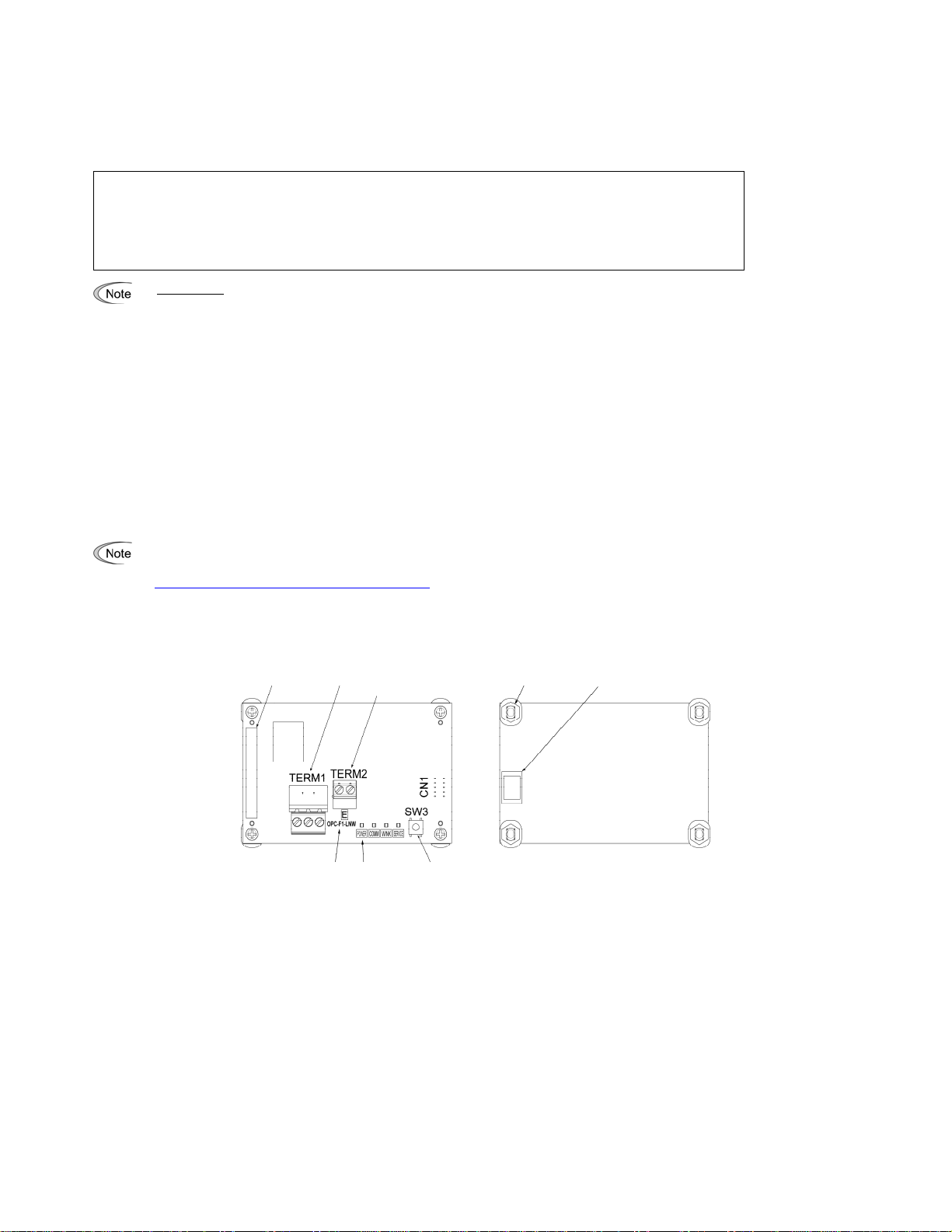
(3) The model name "OPC-F1-LNW" is printed on the card. (See Figure 1.)
(4) A barcode label (representing Neuron ID) is attached to the card. Another barcode label (not attached to the card) comes with the card.
If you suspect the product is not working properly or if you have any questions about your product, contact your Fuji Electric representative.
This card is applicable to all FRENIC-Eco series of inverters and all software versions.
- None of an XIF file, resource file, and LNS plug-in comes with the LONWORKS interface card.
These files can be downloaded for free (registration required) from our website at:
http://web1.fujielectric.co.jp/Kiki-Info-EN/User/index.html
(Fuji Electric FA Components & Systems Co., Ltd. Technical Information)
- A LONWORKS integration tool does not come with the card. Get the one separately. The recommended tool is Echelon LonMaker.
- The Neuron ID is printed on the barcode label. The barcode symbology is Code 39.
Barcode label
(Neuron ID)
LON
WORKS terminal bloc
Ground terminal bloc
4 sp
acers
CN1
Model name
Status indicator
LEDs
Serv
ice button
Figure
1 Front of the Card Figure 2 Back of the Card
3
Page 6
Chapter 3 Basic Functions
3.1 Service Button
The service button is used to commission the LONWORKS interface card to the network. Pressing the button outputs the Neuron ID to the network.
Setting inverter's function code o30 to "1" is functionally equivalent to the depression of the service button. The function code enables commission from
e keypad so as not to require removing the inverter cover, making it safe and convenient. th
When pressing the service button, take extra care not to touch the inverter high-voltage section. Setting inverter's function code o30 to "1" is functionally
equivalent to the depression of the service button, so using the function code is recommended for safety.
Electric shock could occur.
3.2 Status Indicator LEDs
The four status indicator LEDs show the status of the card as listed below.
Table 1 LED Status
Name Color Meaning Note
Lights in green Normal --
POWER
COMM Lights in green
WINK Blinks in green WINK message received Blinking 6 times.
SERVICE
1
*
Configuration for ignoring er5 is possible. For details, refer to Chapter 8, Section 8.1 "Specifying an Inverter Reaction to LONWORKS Communications
Errors."
Blinks in green
Blinks in red LONWORKS communications error
Lights in red
Lights in green Service button being pressed --
Blinks in green Unconfigured
Off Configured
Self-diagnostic test running or initialization in
progress during powering on sequence
Hardware error
(Card not properly installed or card faulty)
Occurrence of LONWORKS
communications event*2
This test takes approx. 0.5
second.
The inverter shows er5. *
The inverter shows er4.
The change of an output NV
value lights this LED even if
the cable is not connected.
Including uncommissioned
state
Including commissioned
state.
1
*2 Upon completion of initialization of the card after the power is turned on, an event that outputs all output network variables supported by this card
occurs in order to tell the latest inverter information to the network. Since this event occurs independent of the cable connection/disconnection,
binding/unbinding, and commissioned/not commissioned, it lights the COMM LED. The delay time from the occurrence of the event to the output of the
output network variables can be adjusted with the VSD object, UCPT_SendDelayAfterDevRdy.
For details about UCPT_SendDelayAfterDevRdy, refer to Section 7.3.3 "List of VSD object configuration properties (CPs)."
3.3 Terminal Blocks
The card ha
For wirings, refer to Chapter 5 "Wiring."
3.4 Barcode Label
The Neuron ID a
string and barcode. The barcode symbology is Code 39. One more barcode label comes with the card for application to a network drawing, etc.
s two terminal blocks: LONWORKS and ground.
ssigned to the Neuron chip mounted on the card is printed on the barcode label pasted on the card in both human-readable character
4
Page 7
Chapter 4 Installation
Turn the power off and wait for at least five minutes for inverters of 40 HP or below, or ten minutes for inverters of 50 HP or above, before starting
installation. Further, check that the LED monitor and charge lamp are unlit, and check the DC link circuit voltage between the P (+) and N (-) terminals to
be lower than 25 VDC.
Otherwise, electric shock could occur.
Do not touch any metallic part of the connector for the main unit (CN1) or any electronic component. Otherwise, electronic components may be
damaged by static electricity charged in your body. Also, the stain or adhesion of sweat or dust may adversely affect the contact reliability of the
connector in the long run.
An accident could occur.
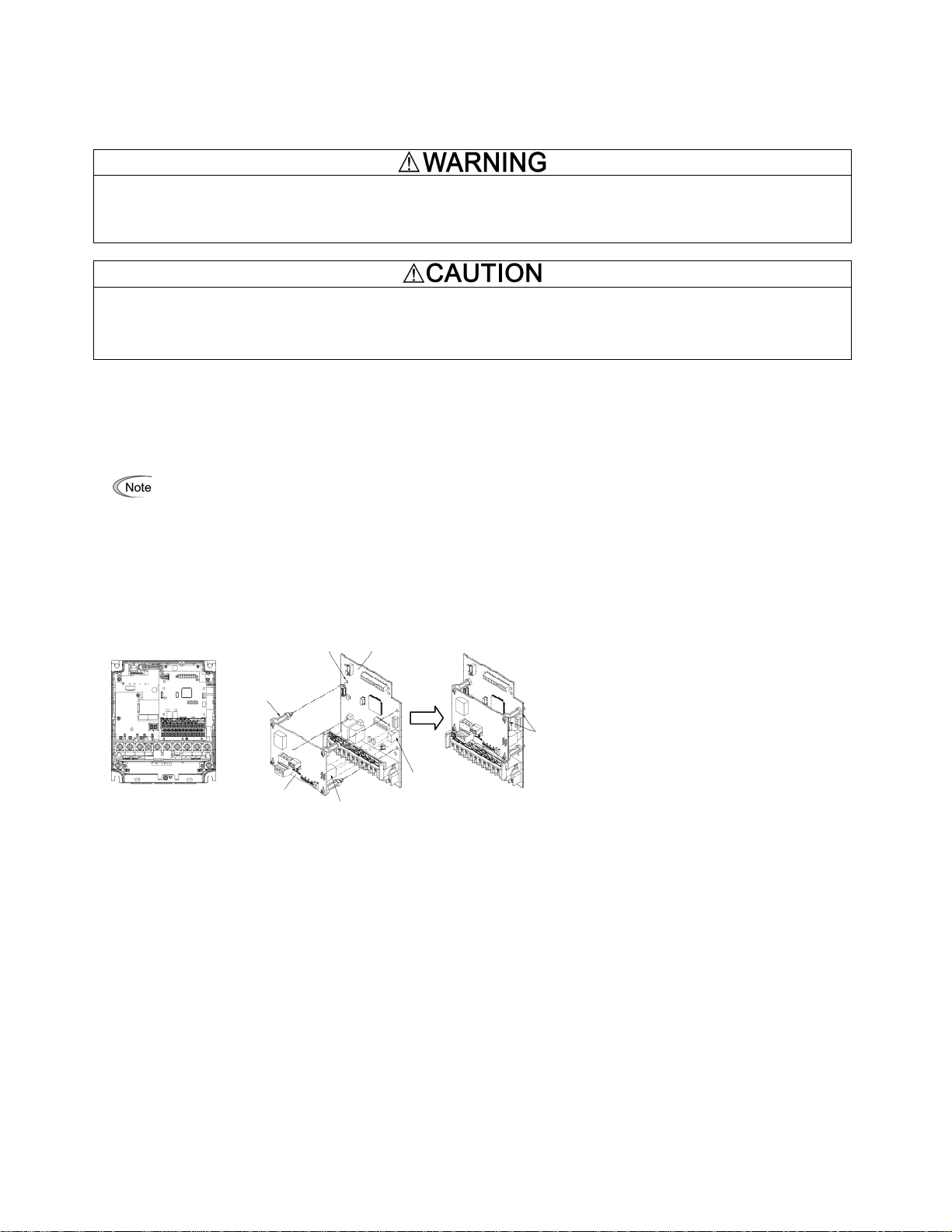
(1) Remove the covers from the inverter to expose the control printed circuit (Figure 3).
For the removal instructions, refer to the FRENIC-Eco Instruction Manual (INR-SI47-1225-E), Chapter 2, Section 2.3 "Wiring." (For inverters of
50 HP or above, also open the keypad enclosure.)
(2) Insert four spacers and connector CN1 on the back of the OPC-F1-LNW (Figure 2) into the four spacer holes and Port A (CN4) on the inverter's
control printed circuit board (PCB) (Figure 4), respectively.
Make sure, visually, that the spacers and CN1 are firmly inserted (Figure 5).
(3) Install the wires for the OPC-F1-LNW.
(4) Put the covers back to their original positions.
For wiring instructions, see Chapter 5.
For the installation instructions, refer to the FRENIC-Eco Instruction Manual (INR-SI47-1225-E), Chapter 2, Section 2.3 "Wiring." (For inverters
of 50 HP or above, also close the keypad enclosure.)
4 spacer holes
Control PCB
LONWORKS interface
card, OPC-F1-LNW
Figure 3 FRN7.5F1S-2J
to
FRN15F1S-2J
(example)
4 spacers
Make sure that there is
no space between
control PCB and
spacers.
CN1
Port A
(CN4)
Figure 4 Mounting the Card Figure 5 Mounting Completed
5
Page 8
Chapter 5 Wiring
s
(1) Use a shielded twist pair cable recommended by LONMARK for network connection.
The recommended cable is LW161S manufactured by Showa Electric Wire & Cable Co., Ltd.
For details about wiring, refer to the "FT3120/FT3150 Smart Transceiver Data Book" published by Echelon. It can be downloaded for free from
our website at:
http://www.echelon.com/support/documentation/manuals/OEM
(2) Wiring to the LONWORKS' terminal block (TERM1)
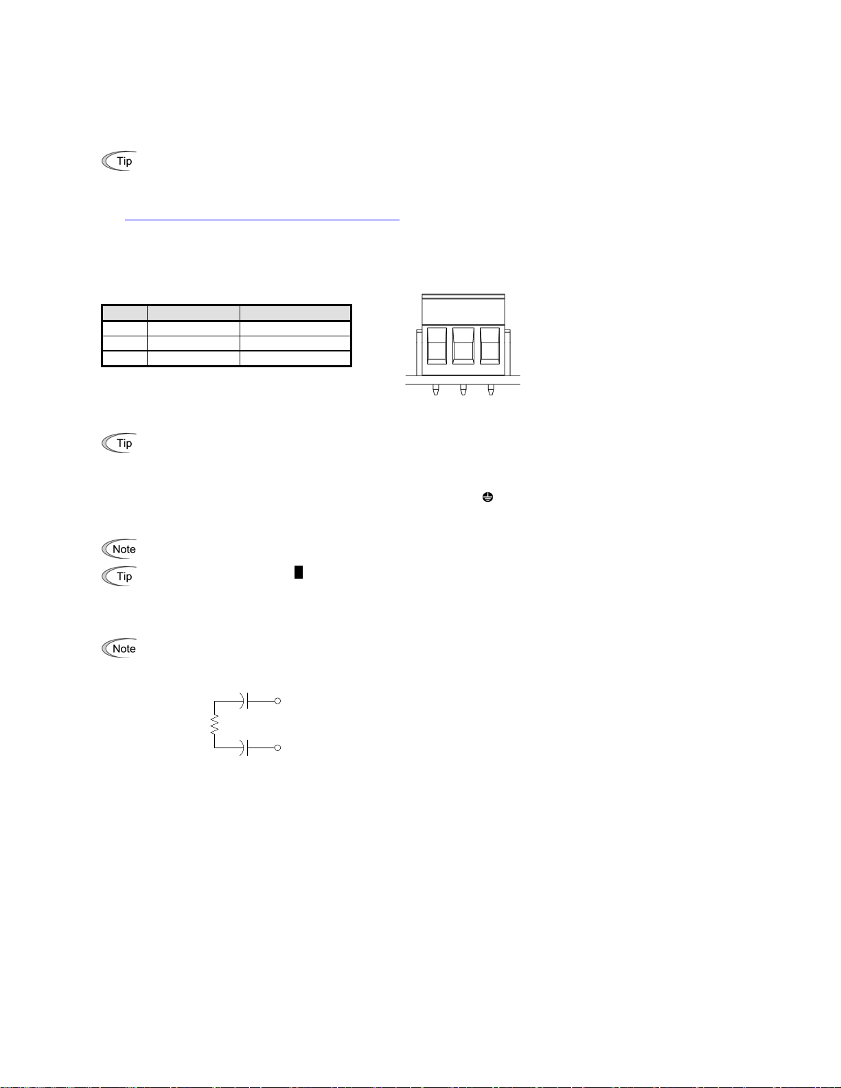
The terminal block uses a pluggable 3-pin connector shown in Figure 6. Table 2 shows the pin assignment.
The applicable pluggable connector is "MSTB2.5/3-ST-5.08" manufactured by Phoenix Contact Corporation.
1
Table 2 Pin Assignment on TERM1
Pin # Pin Assignment Description
1 SD Shield
2 NET B Signal line
3 NET A Signal line
Figure 6 Pluggable Connector
on LONWORKS Terminal Block
The network wiring is polarity insensitive. Connecting the two wires of the network cable to NET A and NET B enables communication,
without regard to polarity. Wire crossing between the card and other nodes causes no problem.
(3) Wiring to the ground terminal block (TERM2)
Using an electric cable, connect one of the two wires to the grounding terminal (
short-circuited, either one can be connected.
Applicable wire size: AWG17 to 16 (1.0 to 1.3 mm
To keep noise immunity high, be sure to connect a grounding wire to the terminal block. Otherwise, excessively poor communication
performance may result, in the worse case, communication is impossible.
This terminal block is marked with E by its side. "E" signifies earth (ground).
2
)
(4) Network termination
Free topology wiring requires a single terminating resistor per segment.
No terminating resistor comes with the card. Prepare resistors separately. The recommended terminating resistor is "TP/FT-10 Channel
Terminator Model No.44100" manufactured by Echelon.
C1
+
NET A
R: 52.3Ω 1 %, 1/8W
C1, C2: 100 µF, 50 VDC min. voltage rating
2 3
G) on the inverter. Since these two wires are internally
R
C2
+
NET B
Figure 7 LONWORKS Network Termination
6
Page 9

Chapter 6 Function Code Settings Required for LONWORKS Communication
r
t
To enable run, frequency, and nviXcmd_1 to 5 commands via the LONWORKS network, the inverter requires setting function codes listed in Table 3.
To enable particular NVs, modify the function codes listed in Table 4. To enable other functions, modify them listed in Table 5.
For details about function codes, refer to the FRENIC-Eco Instruction Manual (INR-SI47-1225-E), Chapter 5 "FUNCTION CODES" and RS-485
Communication User's Manual (MEH448), Chapter 5, Section 5.2 "Data Formats."
Function code settings in Tables 3 through 5 are not essential for LONWORKS communication. Those settings can be made either before or afte
commissioning of the card.
IMPORTANT
After commissioning of the card, be sure to restart the inverter or reset it w
operate normally just by turning it online.) Until it is done, the changes made for network variables (NVs) or configuration properties (CPs) will no
be validated on the inverter.
To enable particular NVs listed below, modify the following function codes in addition to the ones listed in Table 3.
Table 3 Function Code Settings for Enabling Run, Frequency and nviXcmd1 to 5 Commands via LONWORKS Network
Function
code
y98 Run and frequency
y99 Run and frequency
E01 to
E05
E98 Command assignment to
Table 4 Function Codes Required for Enabling nviAOcmd and nviDOcmd_Y1 and Y2
NV to be
Enabled
nviAOcmd F31, F35 Analog output to terminals [FMA] and [FMP] (or
nviDOcmd_Y1,
Y2
Description
commands via
LONWORKS network
commands via Loader
Command assignment to
terminals [X1] to [X5]
terminal [FWD]
Function
code
[FMI])
E20, E21 Signal assignment to terminals [Y1] and [Y2] 0, 1 27 (Universal
Factory
default
0 3 Setting UCPT_LinkFunc
0 0 No change is required
6, 7, 8, 11,
35
98 98 No change is required
Description
ith a LONWORKS integration tool (e.g., LonMaker). (The card does not
Setting Required Remarks
is equivalent to setting
y98.
from the factory default.
Except the following.
24, 1024 (LE selected)
35, 1035 (LOC
selected)
- Even if LE is selected,
turning the physical
terminal ON causes no
problem.
- Even if LOC is selected,
the physical terminal
OFF causes no
problem.
from the factory default.
Factory
default
0, 0 10 (Universal
AO)
DO)
Setting
Required
7
Page 10

To enable other functions, modify function codes listed in Table 5.
Table 5 Function Codes Required for Enabling Other Functions
Function
code
o27*1 Operation selection at
occurrence of LONWORKS
Description
Factory
default
0 0 to 15 Can be specified by
Setting range Remarks
UCPT_CblLossMode.
communications error
o28*1 Timer at occurrence of
LONWORKS communications
0.0 s 0.0s to 60.0 s Can be specified by
UCPT_CblLossTimer.
error
o30 Service button equivalent 0 0 to 255 Setting o30 to "1" or above is
functionally equivalent to the
depression of the service
button.
Once o30 data is changed, it
will automatically revert to
"0."
W90 LONWORKS card software
version
W95 Count of communications errors
between card and inverter
W96 Contents of communications
errors between card and inverter
(Transmission errors only *2)
Depends
on cards
-(Only for
monitor)
0 --
(Only for
monitor)
0 --
(Only for
monitor)
4-digit in decimal notation.
(Ex.) Ver. 1.42 is shown as
0142.
Contents of the most recent
communications error.
The error codes are identical
with the ones used in the Fuji
general-purpose inverter
*3
protocol.
*1 For details about o27 and o28, refer to Chapter 8, Section 8.1 "Specifying an Inverter Reaction to LONWORKS Communications Errors."
*2 Application errors except transmission errors will be written into the VSD object, nv34 nvoAccessErrCode. For details about error code contents, refer
to Chapter 7, Section 7.6.2 "Writing to inverter's function codes."
*3 For error code details, refer to the RS-485 Communication User's Manual (MEH448), Chapter 4, Section 4.3 "Communications Errors."
8
Page 11
Chapter 7 Object Details
7.1 Overview
This card supports two objects--a node object and Variable Speed Motor Drive object (VSD object). This chapter provides detailed information on these
objects.
7.2 Node Object
7.2.1 Node object overview
The node object processes the system events in LONWORKS network communication for this card. (Usually any intervention of users or integrators
is not required.)
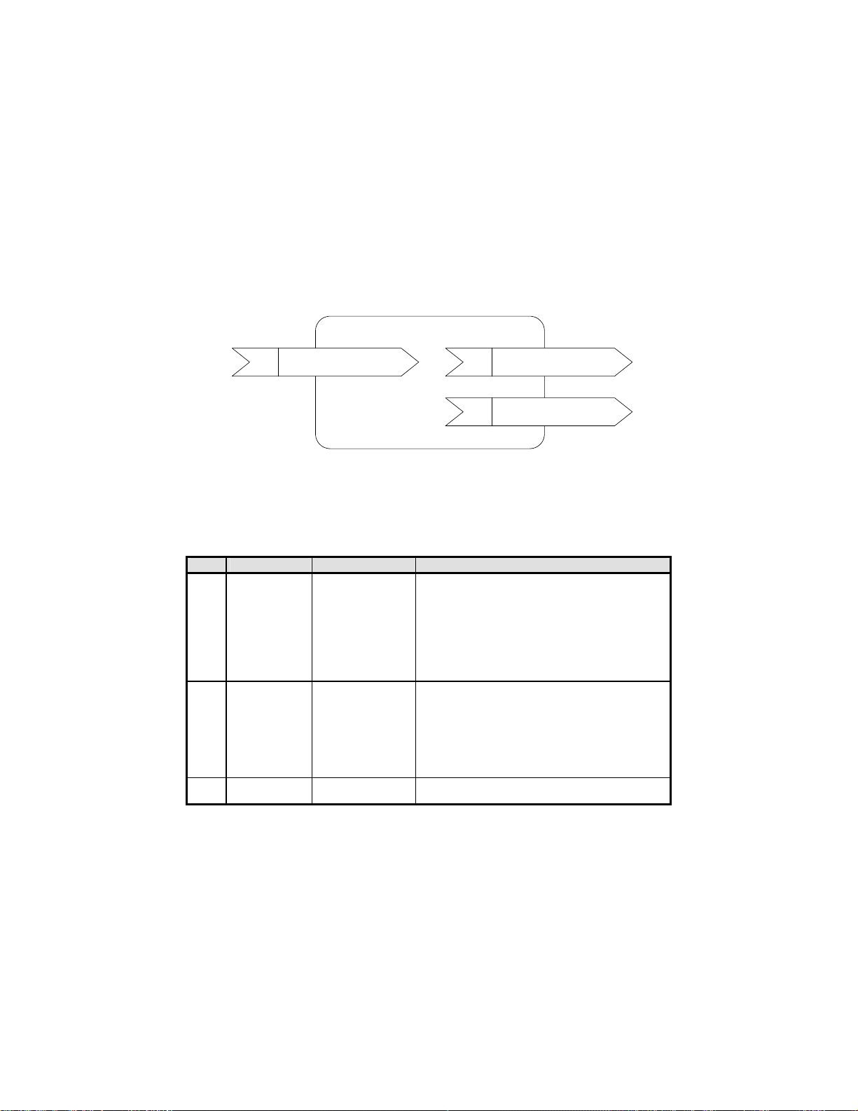
Figure 8 illustrates the relationship between a node object and network variables (NVs).
Node Object #0
nviRequest
nv1
SNVT_obj_request
Figure 8 Overview Structure of Node Object
7.2.2 List of node object network variables (NVs)
Table 6 lists node object network variables supported on this card.
Table 6 Node Object Network Variables
Index Variable name Variable type Description
nv1 nviRequest SNVT_obj_request
nv2 nvoStatus SNVT_obj_status This variable is used to report the status of an object.
nv8 nvoFileDirectory SNVT_address
nvoStatus
nv2
nv8
SNVT_obj_status
nvoFileDirectory
SNVT_adress
This variable is used to request a particular mode for an
object.
Requests supported:
- RQ_NORMAL(0)
- RQ_ENABLED(7)
- RQ_DISABLED(1)
- RQ_UPDATE_STATUS(2)
- RQ_REPORT_MASK(5)
- RQ_CLEAR_ALARM(10)
Statuses supported:
- object_id
- invalid_id
- invalid_request
- disabled
- in_alarm
- report_mask
This variable is used to provide the starting address of
the directory that contains the configuration file.
9
Page 12

7.2.3 NV details
(1) nviRequest
Table 7 lists responses to the request modes of nviRequest.
Table 7 Responses to nviRequest
Request Node object response VSD object response
RQ_NORMAL(0) - Enables the node object and NVs
RQ_ENABLE(7) Same as above. Same as above.
RQ_DISABLE(1) - Stops the motor if running.
RQ_UPDATE_STATUS(2) - Updates nvoStatus and outputs the
RQ_REPORT_MASK(5) - Reports supported requests as "1."
RQ_CLEAR_ALARM(10) - Resets alarm.
All other requests - Returns an invalid request
All other objectIDs - Returns an invalid request
(2) nvoStatus
Table 8 lists the status network variables supported and their descriptions.
Stat us Description
object_id Returns the object ID designated by the Request.
invalid_id Turns "1" when Request is issued to an object with invalid ID.
invalid_request Turns "1" for an invalid request response.
disabled Turns "1" when the VSD object is disabled.
in_alarm Turns "1" when the inverter is in an alarm state or has not solved an alarm.
report_mask Turns the value of the supported status to "1."
to the normal mode.
- Updates nvoStatus and outputs the
new object status.
- Keeps the node object enabled.
- Updates nvoStatus and outputs the
new object status.
new object status.
- Updates nvoStatus and outputs the
new object status.
- Updates nvoStatus and outputs the
new object status.
response.
- Updates nvoStatus and outputs the
new object status.
response.
- Updates nvoStatus and outputs the
new object status.
Table 8 Status Network Variables Supported
7.2.4 Configuration properties (CPs)
Configuration properties are not supported for the node object.
- Enables the VSD object and NVs to
the normal mode.
- Updates nvoStatus and outputs the
new object status.
- Stops the motor if running.
- Disables the VSD object, ignores NV
input, and forbids its output to
transmit.
- Updates nvoStatus and outputs the
new object status.
- Updates nvoStatus and outputs the
new object status.
- Reports supported requests as "1."
- Resets alarm.
- Updates nvoStatus and outputs the
new object status.
- Returns an invalid request response.
- Updates nvoStatus and outputs the
new object status.
- Returns an invalid request response.
- Updates nvoStatus and outputs the
new object status.
10
Page 13

7.3 VSD Object
7.3.1 VSD object overview
The Variable Speed Motor Drive (VSD) object allows you to control the inverter and monitor its running status. Figure 9 illustrates an overview
structure of a VSD object. Letters in parenthesis at the tail of the NV name strings show the names of the inverter's function codes that are involved
by the related NVs.
For details about the function codes in parenthesis, refer to the RS485 Communication User's Manual (MEH448), Chapter 5, "FUNCTION CODES
AND DATA FORMATS."
VSD Object #1
nviDrvSpeedStptnv1
nviDrvSpeedScalenv2
nvoDrvSpeednv4
nvoDrvCurnt (M11)nv3
nvoDrvVolt (M12)nv5
nvoDrvPwr (M10)nv6
nvoDrvRunHours (W79)nv7
nviOpecmd (S06)nv8
nviFreqcmd (S05)nv9
nviReadParamCodenv10
nviWriteParaCodenv11
nviWriteParamValnv12
nviAOcmd (S12)nv13 nvoAIVal_1 (M49)nv35
nviDOcmd_Y1 (S07)nv14
nviDOcmd_Y2 (S07)nv15
nviFWDcmd (S06)nv16
nviXcmd_1 (S06)nv17
・・・
nviXcmd_5 (S06)nv21
nviAlarmReset (S14)nv22
nvoDrvStatus (M14)nv23
nvoOutputFreq (M09)nv24
nvoDrvTorque (M07)nv25
nvoDrvEnergy (W81)nv26
nvoDrvOpeHours(W70)nv27
nvoReadParamValnv33
nvoAccessErrCodenv34
nvoAIVal_2 (M50)nv36
nvoYstatus_1 (M15)nv39
・・・
nvoYstatus_5 (M15)nv43
nvoInAlarm (M14)nv49
nvoAlarm (M16)nv50
nvoAlarmLog (M17~19)nv51
nvoAlarmOpCmd (M39)nv52
nvoAlarmFreq_1 (M31)nv53
nvoAlarmFreq_2 (M35)nv54
nvoOpeTm_1 (W76)nv28
nvoOpeTm_2 (W77)nv29
nvoDCbusCapacity (W75)nv30
nvoDrvTemp_1 (M61)nv31
nvoDrvTemp_2 (M62)nv32
nvoAiVal_3 (M54)nv37
nvoPIDFb (M72)nv38
nvoXstatus_1 (M13)nv44
・・・
nvoXstatus_5 (M13)nv48
nvoAlarmCurrent (X21)nv55
nvoAlarmVolt (M38)nv56
nvoAlarmOpTime (M42)nv57
nvoAlarmPower (X35)nv58
nvoAlarmTorque (M33)nv59
24 Configuration Properties
Figure 9 Overview Structure of VSD Object
11
Page 14

7.3.2 List of VSD object network variables (NVs)
Table 9 lists the summary of VSD object network variables (NVs). The function code column in the table shows their associated inverter's function
codes.
Some of the VSD object input and output NVs are detailed in Sections 7.4 and 7.5, respectively.
Table 9 VSD Object Network Variables
Index Variable name Variable type Descriptions
nv1 nviDrvSpeedStpt SNVT_switch
nv2 nviDrvSpeedScale
SNVT_lev_perce
nt
This input provides start/stop
commands and a low-resolution
speed setpoint.
(as a percentage of
SCPT_nomFreq)
This input provides scaling for a
low-resolution speed setpoint.
(Negative values indicate reverse
motor direction.)
nv3 nvoDrvCurnt SNVT_amp
nv4 nvoDrvSpeed
SNVT_lev_perce
nt
nv5 nvoDrvVolt SNVT_volt
nv6 nvoDrvPwr
SNVT_power_kilo This output reports the output power
nv7 nvoDrvRunHours SNVT_time_hour
nv8 nviOpeCmd SNVT_state
nv9 nviFreqCmd SNVT_freq_hz
nv10
nviReadParamCo
de
SNVT_count
This output reports the output current
(RMS) with 0.1 A resolution.
This output reports the output speed.
(as a percentage of
SCPT_nomFreq)
This output reports the output voltage
(RMS) with 0.1 V resolution.
with 0.1 kW resolution.
This output reports the cumulative
motor run time.
(Diagnostic reference of the
mechanical component service life)
This input provides run commands
including run forward command, run
reverse command, and terminal
commands assigned to
general-purpose, digital input
terminals.
Functionally equivalent to function
code S06 (dedicated to inverter
communication).
This input provides frequency
command with 0.1 Hz resolution.
This input specifies a target inverter's
function code to read out its data with
nv33 nvoReadParamVal.
nv11 nviWriteParaCode SNVT_count
This input specifies a target inverter's
function code to write data with nv12
nviWriteParamVal.
nv12 nviWriteParamVal SNVT_count
nv13 nviAOcmd
SNVT_lev_perce
nt
This input contains data to write into
the inverter's function code specified
by nv11 nviWriteParaCode.
This input specifies any output level
for the inverter's analog output
terminal.
Functionally equivalent to function
code S12 (dedicated to inverter
communication).
nv14 nviDOcmd_Y1 SNVT_switch
nv15 nviDOcmd_Y2 SNVT_switch
This input turns the inverter's digital
output terminal [Y1] ON/OFF.
If the value is "1," [Y1] is ON. (Setting
E20 to "27" (Universal DO) is
needed.)
This input turns the inverter's digital
output terminal [Y2] ON/OFF.
If the value is "1," [Y2] is ON. (Setting
E21 to "27" (Universal DO) is
needed.)
Functio
n code
Refer to:
- p. 19
- p. 19
M11 -
- p. 23
M12 -
M10 -
W79 -
S06
S05 p. 20
-
-
-
S12
S07
S07
pp. 20
and 27
pp. 21
and 28
pp. 21
and 28
pp. 21
and 7
pp. 21
and 7
pp. 21
and 7
12
Page 15

Index Variable name Variable type
nv16 nviFWDcmd SNVT_switch
nv17 nviXcmd_1 SNVT_switch
nv18 nviXcmd_2 SNVT_switch
nv19 nviXcmd_3 SNVT_switch
nv20 nviXcmd_4 SNVT_switch
nv21 nviXcmd_5 SNVT_switch
nv22 nviAlarmReset SNVT_switch
nv23 nvoDrvStatus SNVT_state
nv24 nvoOutputFreq SNVT_freq_hz
nv25 nvoDrvTorque
SNVT_lev_perce
nt
nv26 nvoDrvEnergy SNVT_elec _kwh
nv27 nvoDrvOpeHours SNVT_time_hour
nv28 nvoOpeTm_1 SNVT_time_hour
nv29 nvoOpeTm_2 SNVT_time_hour
nv30
nvoDCbusCapacty SNVT_lev_perce
nt
nv31 nvoDrvTemp_1 SNVT_temp
nv32 nvoDrvTemp_2 SNVT_temp
nv33
nvoReadParamV
al
SNVT_count
Descriptions Refer to:
This input turns terminal command
FWD (bit XF of S06) ON/OFF, which
is assigned to the inverter's digital
input terminal [FWD] with function
code E98.
FWD runs a motor forward by factory
default.
This input turns a terminal command
(bit X1 of S06) ON/OFF, which is
assigned to the inverter's digital input
terminal [X1] with function code E01.
This input turns a terminal command
(bit X2 of S06) ON/OFF, which is
assigned to the inverter's digital input
terminal [X2] with function code E02.
This input turns a terminal command
(bit X3 of S06) ON/OFF, which is
assigned to the inverter's digital input
terminal [X3] with function code E03.
This input turns a terminal command
(bit X4 of S06) ON/OFF, which is
assigned to the inverter's digital input
terminal [X4] with function code E04.
This input turns a terminal command
(bit X5 of S06) ON/OFF, which is
assigned to the inverter's digital input
terminal [X5] with function code E05.
Turning this variable ON clears alarm
in the inverter.
Once it turns ON, it automatically
returns to OFF.
This output reports the running
status.
Functionally equivalent to function
code M14 (dedicated to inverter
communication).
This output reports the output
frequency with 0.1 Hz resolution.
This output reports the output torque
as a percentage of the rated torque
with 0.005% resolution.
This output reports the inverter's
cumulative power consumption in
watt-hours.
This output reports the cumulative
inverter run time.
(Diagnostic reference data for
inverter lifetime)
This output reports the cumulative
run time of electrolytic capacitors on
printed circuit boards.
(Diagnostic reference data for service
lifetime of the control circuit)
This output reports the cumulative
run time of the cooling fan.
This output reports the current
capacitance of the DC link bus
capacitor in %, based on the
capacitance when shipped as 100%.
This output reports the inverter
internal temperature with 1C
resolution.
This output reports the heat sink
temperature with 1C resolution.
This output reports the data of the
function code read.
Functio
n code
S06
S06
S06
S06
S06
S06
pp. 22
and 7
pp. 22
and 7
pp. 22
and 7
pp. 22
and 7
pp. 22
and 7
pp. 22
and 7
S14 p. 22
M14 p. 23
M09 -
M07 -
W81 -
W70 -
W76 -
W77 -
W75 -
M61 -
M62 -
-
pp. 23
and 27
13
Page 16

Index Variable name Variable type
nv34
nvoAccessErrCode UNVT_ErrCode
(1byteHex x 3)
Descriptions Refer to:
This output reports the code of an
error caused after writing to a
function code, together with the
function code accessed.
Only when nv11 and nv12 access a
function code, this output updates its
data and then outputs it onto the
Functio
n code
-
pp. 24
and 28
network.
nv35 nvoAIval_1
nv36 nvoAIval_2
nv37 nvoAIval_3
SNVT_lev_perce
nt
SNVT_lev_perce
nt
SNVT_lev_perce
nt
This output reports the input voltage
at terminal [12].
(100% at 10 V, 0% at 0 V)
This output reports the input current
at terminal [C1].
(100% at 20 mA, 0% at 4 mA)
This output reports the input voltage
at terminal [V2].
M49 p. 24
M50 p. 24
M54 p. 24
(100% at 10 V, 0% at 0 V)
nv38 nvoPIDFb
SNVT_lev_perce
nt
nv39 nvoYstatus_1 SNVT_switch
nv40 nvoYstatus_2 SNVT_switch
nv41 nvoYstatus_3 SNVT_switch
This output reports the PID feedback
value (%).
This output reports the status of
digital output terminal [Y1] whose
function is assigned by E20.
This output reports the status of
digital output terminal [Y2] whose
function is assigned by E21.
This output reports the status of
digital output terminal [Y3] whose
M72 p. 25
M15 p. 25
M15 p. 25
M15 p. 25
function is assigned by E22.
nv42 nvoYstatus_4 SNVT_switch Reserved. - nv43 nvoYstatus_5 SNVT_switch
This output reports the status of
digital output terminal [Y5A/C] whose
M15 p. 25
function is specified by E24.
nv44 nvoXstatus_1 SNVT_switch
This output reports the status of a
terminal command assigned to digital
M13 p. 25
input terminal [X1].
When E01 data is "25" (Universal
DI), this output reports the ON/OFF
state of the physical terminal [X1].
nv45 nvoXstatus_2 SNVT_switch
This output reports the status of a
terminal command assigned to digital
M13 p. 25
input terminal [X2].
When E02 data is "25" (Universal
DI), this output reports the ON/OFF
state of the physical terminal [X2].
nv46 nvoXstatus_3 SNVT_switch
nv47 nvoXstatus_4 SNVT_switch
nv48 nvoXstatus_5 SNVT_switch
This output reports the status of a
terminal command assigned to digital
input terminal [X3].
When E03 data is "25" (Universal
DI), this output reports the ON/OFF
state of the physical terminal [X3].
This output reports the status of a
terminal command assigned to digital
input terminal [X4].
When E04 data is "25" (Universal
DI), this output reports the ON/OFF
state of the physical terminal [X4].
This output reports the status of a
terminal command assigned to digital
input terminal [X5].
When E05 data is "25" (Universal
DI), this output reports the ON/OFF
M13 p. 25
M13 p. 25
M13 p. 25
state of the physical terminal [X5].
nv49 nvoInAlarm SNVT_switch
nv50 nvoAlarm
UNVT_alarm_co
d
(1byte decimal)
This output remains ON when the
inverter is in an alarm state or has not
canceled the recent alarm.
This output reports the code of an
alarm that is occurring or has
occurred most recently.
M14 -
M16 p. 26
14
Page 17

Index Variable name Variable type
y
nv51 nvoAlarmLog
UNVT_alarm_log
(1byte dec x 3)
nv52 nvoAlarmOpCmd SNVT_state
Descriptions Refer to:
This output reports three recent
alarm codes in the order of 1st, 2nd,
and 3rd recent ones.
This output reports the status of a run
command being executed when the
most recent alarm occurred.
Functio
n code
M17
M18
p. 26
M19
M39 -
Same format as nv8 nviOpeCmd.
nv53 nvoAlarmFreq_1 SNVT_freq_hz
nv54 nvoAlarmFreq_2 SNVT_freq_hz
nv55 nvoAlarmCurrent SNVT_amp
nv56 nvoAlarmVolt SNVT_volt
This output reports the status of a
frequency command being executed
when the most recent alarm
occurred, with 0.1 Hz resolution.
This output reports the output
frequency being applied when the
most recent alarm occurred, with 0.1
Hz resolution.
This output reports the output current
being applied when the most recent
alarm occurred, with 0.1 A resolution.
This output reports the output voltage
being applied when the most recent
M31 -
M35 -
X21 -
M38 -
alarm occurred, with 0.1 V resolution.
nv57 nvoAlarmOpTime SNVT_time_hour
This output reports the inverter's run
time being accumulated until the
M42 -
most recent alarm occurred.
nv58 nvoAlarmPower
SNVT_power_kilo This output reports the inverter's
power consumption detected when
the most recent alarm occurred, with
X35 -
0.1 kW resolution.
nv59 nvoAlarmTorque
SNVT_lev_perce
nt
This output reports the inverter's
output torque detected when the
most recent alarm occurred, as a
percentage of the rated torque with
0.005% resolution.
M33 -
Fan-out connection using aliases (branching a single output NV to two or more input NVs on this card) should be avoided because the card ma
miss-fetch any input NV depending upon the fetch timing. If it cannot be avoided, use the repeated mode for the connection messaging service to
prevent miss-fetch of the branched NV aliases.
15
Page 18

7.3.3 List of VSD object configuration properties (CPs)
Table 10 lists the summary of VSD object configuration properties (CPs). The function code column in the table shows their associated inverter's
function codes. Modifying function code data can change the associated CP value.
Some of these CPs have detailed descriptions in Section 7.7 (see the page given in the table below).
Refer to the FRENIC-Eco Instruction Manual (INR-SI47-1225-E), Chapter 5 "FUNCTION CODES" for supplementary information on the CPs.
Table 10 VSD Object CPs
CP name Unit Description Default
SCPT_maxSetpoint 0.005%
Defines the maximum frequency as a
percentage of SCPT_nomFreq.
100.000
%
Functio
n code
F03 -
(60 Hz)
SCPT_minSetpoint 0.005%
SCPT_maxSendTim
e
0.1 s Sets the heartbeat send interval.
Defines the lower limit of the output
frequency as a percentage of
SCPT_nomFreq.
The concerned NV continues
transmitting data at this time intervals,
0.000% F16 -
0.0 s - p. 29
regardless the data changing.
Specifying 0.0 s disables this CP.
SCPT_nomRPM 1 r/min
SCPT_nomFreq 0.1 Hz
SCPT_rampUpTm 0.1 s
SCPT_rampDownTm 0.1 s
Used to enter the nominal speed, 100%
of the percent speed command, in
r/min.
Modifying this CP automatically
replaces the value of SCPT_nomFreq.
Used to enter the nominal frequency,
100% of the percent speed command,
in Hz.
All percent speed commands refer to
this value.
Used to enter the ramp-up time from
the zero to maximum speed.
Used to enter the ramp-down time from
the maximum to zero speed.
1800
r/min
60.0 Hz - p. 19
20.0 s F07 -
20.0 s F08 -
- -
(UCPT_rampUpTm2) - Reserved. - - (UCPT_rampDownT
m2)
SCPT_defScale 0.005%
SCPT_maxRcvTime 0.1 s Sets the heartbeat receive interval.
- Reserved. - - -
Contains the default value for
nviDrvSpeedScale.
If the concerned NV receives no data
within this interval, it interprets the
100.000
%
0.0 s
- -
p. 29
transmission as being broken.
Specifying 0.0 s disables this CP.
SCPT_minDeltaLevel 0.5%
Sets the minimum data change rate for
an output NV to start data transmission.
If the data change rate exceeds this
value, the concerned NV interprets the
data as being changed, starting data
transmission.
0.0% p. 30
Specifying 0.0% disables this CP.
SCPT_minSendTime 0.1 s
Sets the minimum pause time for an
output NV to start data transmission.
Once the concerned NV finishes data
transmission, it does not start data
transmission until this time has elapsed
even if the data change rate exceeds
0.5 s p. 30
SCPT_minDeltaLevel.
Setting 0.0 s disables this CP.
UCPT_BaseFreq 0.1 Hz
Sets the base frequency of the inverter
for motor 1.
50.0 Hz F04 -
(UCPT_JogFreq) - Reserved. - - UCPT_JumpFreq 0.1 Hz x 4
Contains an ensemble of four inverter's
function codes specified in the array
order shown below.
"Jump frequency 1, 2, 3 and jump
frequency band"
0.0 Hz,
0.0 Hz,
0.0 Hz,
3.0 Hz
C01,
C02,
C03,
C04
Refe
r to:
-
16
Page 19

CP name Unit Description Default
UCPT_LinkFunc 1
Switches run and speed commands
between "enable" and "disable" via the
0
Functio Refe
n code r to:
y98 p. 7
LONWORKS network.
Functionally equivalent to function code
y98.
Setting y98 data to "3" enables run and
speed commands.
UCPT_multStepFreq
1
UCPT_PIDsettings
0.01 Hz
0.001,
0.1 s,
0.01 s,
0.1 s
Sets the frequency to be applied when
multistep frequency 1 is selected.
Multistep frequency: Assigning terminal
commands to digital input terminals [X1]
to [X5] and [FWD] with E01 to E05 and
E98 and turning those terminals
ON/OFF can select the multistep
frequency.
Contains an ensemble of four PID
parameters specified in the array order
shown below.
"P gain, I time, D time and feedback
0.00 Hz C05 -
0.100,
0.0 s,
0.00 s,
0.5 s
J03,
J04,
J05,
J06
-
filter time constant"
UCPT_StartFreq 0.1 Hz Sets the starting frequency. 0.5 Hz F23 UCPT_StopFreq 0.1 Hz Sets the stop frequency. 0.2 Hz F25 (UCPT_TorqLimit) - Reserved. - - UCPT_CblLossMode 1
Specifies an action to follow when a
communications line break error occurs
0 o27 p. 31
on the LONWORKS network.
Functionally equivalent to function code
o27.
UCPT_CblLossTimer 0.1 s
UCPT_FlyingStart
Mode
UCPT_momentaryP
wr
LossMode
1
1
UCPT_AutoRestart 1
Sets the timer to determine the issuing
timing of er5 alarm triggered by a
communications line break on the
LONWORKS network.
Functionally equivalent to function code
o28.
Specifies the auto search for idling
motor's speed.
In the auto search mode, the frequency
can be specified by function code H17.
Specifies the restart mode after a
momentary power failure.
Functionally equivalent to function code
F14.
Specifies the number of auto-resetting
times for automatically escaping the
0.0 s o28 p. 31
0
(Disable)
H09 -
1 F14 -
0 H04 -
tripped state.
Functionally equivalent to function code
H04.
H05 specifies the reset interval.
UCPT_SendDelay
AfterDevRdy
0.1 s
Specifies the data transmission start
delay time for the LONWORKS
interface card.
The output NV starts data transmission
after this delay time has elapsed from
when the card is powered up or
receives a reset command from the
LONWORKS integration tool.
This CP should be used to strictly
manage the starting time of data
0.0 s ― -
transmission on the whole network.
Specifying 0.0 s makes the NV start
data transmission upon completion of
initialization of the card. *1
*1 This LONWORKS interface card needs approx. 0.5 second for initialization. Therefore, specifying less than 0.5 second cannot start data transmission
from the output NV until approx. 0.5 second elapses.
When the card is powered up, it transmits all output NVs to validate the latest inverter settings on the LONWORKS network.
17
Page 20

Immediately after commissioning, the LONWORKS integration tool temporarily monitors CP default values, so those CP values do no
t
P
e
necessarily match the inverter's function code settings. This is, however, only apparent and the inverter runs with its function code settings.
To make the monitored CP values match the inverter's settings, use the LONWORKS integration tool to execute the "Synchronize CP" command
(e.g., ReSync CPs in LonMaker) and upload the CP values of this card. Or, use any LonMaker proprietary plug-in for easy uploading of C
values. For instructions on how to get the plug-ins, refer to Chapter 2 "Acceptance Inspection."
Modifying CP-associated function codes from the keypad does not automatically update the CP values being monitored by the LONWORKS
integration tool. This is, however, only apparent and the modification is validated on the associated CPs without any problems.
To update the monitored CP values, use the LONWORKS integration tool to execute the "Synchronize CP" command (e.g., ReSync CPs in
LonMaker) and upload the CP values of this card. Or, use any LonMaker proprietary plug-in for easy uploading of CP values in the same way as
the above note.
The moment the LONWORKS integration tool sets CP values (new or unchanged values), all output NVs implemented on this card output th
latest data at that time. Use this feature to update the NVs on the network with the latest data.
In addition, switching the inverter from offline to online also outputs all output NVs as well.
18
Page 21

7.4 VSD Object Input Network V ariables
t
(1) nv1 nviDrvSpeedStpt
This NV controls the inverter's run/stop and frequency commands via the LONWORKS network.
- Variable type: SNVT_switch
Table 11 Operation of nviDrvSpeedStpt
state value Operation
0 NA Run command OFF
1 0.0 (%) Zero speed command (No torque generated)
1 0.5 to 100.0 (%) Run at 0.5 to 100.0% frequency
-1 (0xFF) NA Invalid
- Default setting: state = -1, value = 0
The card calculates the frequency command value with nviDrvSpeedStpt.value, nviDrvSpeedScale and SCPT_nomFreq.
Frequency command (Hz) = nviDrvSpeedStpt.value (%) x nviDrvSpeedScale (%) x SCPT_nomFreq (Hz)
Each time any one of the three terms in the above equation is entered, the card calculates the frequency command again and overwrites the
previous value with new one, regardless of whether the inverter is running or on halt. If state = 0xFF, however, no recalculation takes place even with
any input.
The frequency command can be specified with this NV and nv9 nviFrecmd. If both of these NVs are specified, the last one takes effec
on the inverter (Last command has priority).
To enable the inverter's run/stop and frequency commands via the LONWORKS network, either of the following settings is required.
UCPT_LinkFunc = 3 or inverter's function code y98 = 3
- CPs for control of the affected network bandwidth: SCPT_maxRcvTime
(2) nv2 nviDrvSpeedScale
This NV specifies the motor rotational direction and frequency command.
- Variable type: SNVT_lev_percent
- Data setting range: -163.840 to 163.830% (0.005% resolution)
If entering 163.835% (invalid), for example, the card ignores the entry and the inverter runs with the previous value.
- Default setting: Value specified by SCPT_defScale
- CPs for control of the affected network bandwidth: SCPT_maxRcvTime
19
Page 22

(3) nv8 nviOpecmd
t
This NV specifies the inverter data of run forward/reverse, digital input terminals [X1] to [X5], [FWD] and [REV]. The command format of this NT is the
same as that of function code S06.
15 14 13 12 11 10 9 8 7 6 5 4 3 2 1 0
ALM
RST
[REV]
[FWD
- - - - - - X5 X4 X3 X2 X1 REV FWD
]
FWD, REV: Run forward/reverse commands to the inverter
X1 to X5: Terminal command assignment fields for inverter's digital inputs [X1] to [X5]
[FWD], [REV]: Run forward/reverse terminal command assignment fields for inverter's digital inputs [FWD] and [REV]
ALMRST: Switching from ON to OFF clears inverter alarms.
- Variable type: SNVT_state
- Default setting: 0000000000000000 (16 bit binary)
- CPs for control of the affected network bandwidth: SCPT_maxRcvTime
To validate this NV entry on the inverter, any of the following settings is required.
UCPT_LinkFunc = 2 or 3, or inverter's function code y98 = 2 or 3
(4) nv9 nviFreqcmd
This NV specifies the frequency command in Hz with 0.1 Hz resolution.
- Variable type: SNVT_freq_hz
- Data setting range: 0.0 to 6553.5 Hz (Valid range for inverter: 0.0 to 400.0 Hz)
- Default setting: 0.0 Hz
- CPs for control of the affected network bandwidth: SCPT_maxRcvTime
The frequency command can be specified with this NV and nv1 nviDrvSpeedStpt. If both of these NVs are specified, the last one takes effec
on the inverter (Last command has priority).
To validate this NV entry on the inverter, any of the following settings is required.
UCPT_LinkFunc = 1 or 3, or inverter's function code y98 = 1 or 3
(5) nv10 nviReadParamCode
This NV specifies a target inverter's function code to read out its data with nv33 nvoReadParamVal.
For details about readout of function code data, refer to Section 7.6.1 "Reading from inverter's function codes."
- Variable type: SNVT_count
- Data setting range: 0000 to FFFF (hexadecimal)
- Default: 0000 (hexadecimal)
- CPs for control of the affected network bandwidth: None
20
Page 23

(6) nv11 nviWriteParaCode, nv12 nviWriteParamVal
e
Data contained in nv12 will be written into a function code specified by nv11.
For details about writing data, refer to Section 7.6.2 "Writing to inverter's function codes."
- Variable type: SNVT_count
- Data setting range: 0000 to FFFF (hexadecimal)
- Default setting: 0000 (hexadecimal)
- CPs for control of the affected network bandwidth: None
(7) nv13 nviAOcmd
This NV outputs its value onto the inverter's analog output terminal [FMA/FMP/FMI] (same as universal AO).
To terminal [FMA], the NV outputs 0 to 10 VDC or 4 to 20 mADC. To terminal [FMP], it outputs a square wave pulse train prescribed by the inverter.
For [FMI], it outputs 4 to 20 mADC.
This allows the inverter to work as an analog output device having a single channel, physical analog output.
For details about terminals [FMA] and [FMP] (or [FMI]), refer to the FRENIC-Eco Instruction Manual (INR-SI47-1225-E), Chapter 2, Section
2.3.7 "Wiring for control circuit terminals" and Chapter 5, Section 5.2 "Overview of Function Codes," F31 and F35.
- Variable type: SNVT_lev_percent
- Data setting range: -163.840 to 163.830% (Valid range for inverter: 0.000 to 105.000%)
Setting 163.835% (invalid), for example, will be ignored so that the inverter runs with the previous value.
- Default setting: 0.000%
- CPs for control of the affected network bandwidth: SCPT_maxRcvTime
To validate this NV entry on the inverter, either of the following settings is required.
For [FMA], inverter's function code F31 = 10
For [FMP] (or [FMI]), F35 = 10
It is possible to enable both [FMA] and [FMP], however, both terminals output the same analog level signals.
(8) nv14 nviDOcmd_Y1, nv15 nviDOcmd_Y2
The nv14 or nv15 outputs its ON/OFF value onto inverter's digital output terminal [Y1] or [Y2], respectively (same as universal DO). This allows the
inverter's physical Y terminals to work as a 2-bit (max.) digital output device.
For details about Y terminals, refer to the FRENIC-Eco Instruction Manual (INR-SI47-1225-E), Chapter 2, Section 2.3.7 "Wiring for control circuit
terminals" and Chapter 5, Section 5.2 "Overview of Function Codes," E20 and E21.
- Variable type: SNVT_switch
- Data setting range: value = 0.0 to 100.0%, state = 1, 0, -1
- Default settings: value = 0.0%, state = 0
- CPs for control of the affected network bandwidth: SCPT_maxRcvTime
Do not use nviDOcmd_Y1 or nviDOcmd_Y2 as a bit array. This is because, in LONWORKS communication, two or more variables ar
never output concurrently, so the card may miss-fetch the bit array at the timing when the data gets validated on the inverter. Accordingly, the
inverter could receive it as unexpected data. To handle them as a bit array, read out S07 by the function code readout feature.
To validate this NV entry on the inverter, either of the following settings is required.
For [Y1], inverter's function code E20 = 27
For [Y2], E21 = 27
21
Page 24

(9) nv16 nviFWDcmd
s
s
r
This NV controls the ON/OFF of inverter's digital input terminal [FWD]. Command assignment to [FWD] is made with function code E98. The factory
default command is "Run forward."
For details about function code E98, refer to the FRENIC-Eco Instruction Manual (INR-SI47-1225-E), Chapter 5 "FUNCTION CODES."
- Variable type: SNVT_switch
- Data setting range: value = 0.0 to 100.0%, state = 1, 0, -1
- Default setting: value = 0.0%, state = 0
- CPs for control of the affected network bandwidth: SCPT_maxRcvTime
To assign the "Run reverse" command to terminal [FWD], it is necessary to assign a terminal command other than "Run reverse" to terminal
[REV] using function code E99.
The run command issued by this NV is independent of the one issued by nviDrvSpeedStpt, so turning ON either one of those run command
runs the motor. To stop it, therefore, concurrently turn OFF both of them issued by the two NVs.
To validate this NV entry on the inverter, any of the following settings is required.
UCPT_LinkFunc = 2 or 3, or inverter's function code y98 = 2 or 3
(10) nv17 to nv21 nviXcmd_1 to nviXcmd_5
These NVs control the ON/OFF of inverter's digital input terminals [X1] to [X5]. Command assignments to [X1] to [X5] are made with function codes
E01 to E05, respectively.
For details about function codes E01 to E05, refer to the FRENIC-Eco Instruction Manual (INR-SI47-1225-E), Chapter 5 "FUNCTION CODES."
- Variable type: SNVT_switch
- Data setting range: value = 0.0 to 100.0%, state = 1, 0, -1
- Default settings: value = 0.0%, state = 0
- CPs for control of the affected network bandwidth: SCPT_maxRcvTime
Do not use any of nviXcmd_1 to nviXcmd_5 as a bit array (e.g., multistep speed command). This is because, in LONWORKS
communication, two or more variables are never input concurrently, so the card may miss-fetch the bit array at the timing when the data get
validated on the inverter. Accordingly, the inverter could transmit it as unexpected data. To handle them as a bit array, use nv8 nviOpecmd,
instead.
Depending on the command assignment to inverter's digital input terminals, some ON/OFF commands via the LONWORKS network using
these NVs may be ignored. On the other hand, some commands entered from the terminal block may be unconditionally validated. Fo
details about these events, refer to the RS485 Communication User's Manual (MEH448), Chapter 5, Section 5.1.2 [2] "Operation command
data."
To validate this NV entry on the inverter, any of the following settings is required
UCPT_LinkFunc = 2 or 3, or inverter's function code y98 = 2 or 3
(11) nv22 nviAlarmReset
Setting the ON value to this NV releases the inverter's trip state. If any alarm factor persists at the entry of the ON value, the trip state cannot be
released. After the entry of the ON value, the NV state automatically reverts to OFF.
- Variable type: SNVT_switch
- Data setting range: value = 0.0 to 100.0%, state = 1, 0, -1
- Default setting: value = 0.0%, state = 0
- CPs for control of the affected network bandwidth: None
22
Page 25

7.5 VSD Object Output Network V ariables
This section describes VSD object output network variables that need supplemental explanations. For variables not found in this section, refer to Section
7.3 "VSD Object."
(1) nv4 nvoDrvSpeed
This NV outputs the inverter's output frequency as a percentage of SCPT_nomFreq (Base frequency).
- Variable type: SNVT_lev_percent
- Data setting range: -163.840 to 163.830% (0.005% resolution)
- CPs for control of the affected network bandwidth: SCPT_maxSendTime, SCPT_minSendTime and SCPT_minDeltaLevel
- Output timing: At the time of data change, at intervals specified by SCPT_maxSendTime (if specified), after the time specified by
(2) nv23 nvoDrvStatus
This NV outputs the current inverter status. The format of this NV is the same as that of the inverter's communication function code M14.
15 14 13 12 11 10 9 8 7 6 5 4 3 2 1 0
BUS
Y
FWD, REV : Run forward, Run reverse IL : During output current limiting
EXT : During DC-braking (or Pre-exciting) ACC : During acceleration
INT : Inverter shutdown DEC : During deceleration
BRK : Braking ALM : Alarm relay output
NUV : DC link bus voltage established (0: Undervoltage) RL : Communication active
VL : Output voltage limiting BUSY : Busy in writing function codes
- Variable type: SNVT_state
- CPs for control of the affected network bandwidth: SCPT_maxSendTime and SCPT_minSendTime
- Output timing: At the time of data change, at intervals specified by SCPT_maxSendTime (if specified), or after the time specified by
(3) nv33 nvoReadParamVal
This NV reads out data from the inverter's function code specified by nv10 nviReadParamCode.
For details about readout of function code data, refer to Section 7.6.1 "Reading from inverter's function codes."
- Variable type: SNVT_count
- Data setting range: 0000 to FFFF (hexadecimal)
- CPs for control of the affected network bandwidth: SCPT_maxSendTime
- Output timing: At the input time of nv10 nviReadParamCode or at intervals specified by SCPT_maxSendTime (if specified)
SCPT_minSendTime (if specified), or when the data change rate exceeds the value specified by SCPT_minDeltaLevel (if
specified)
- - RL ALM DEC ACC IL VL - NUV BRK INT EXT REV FWD
SCPT_minSendTime (if specified)
This NV is issued after input of nviReadParamCode, regardless of whether the data has been changed or not.
23
Page 26

(4) nv34 nvoAccessErrCode
0
After completion of writing of inverter's function code data with nv11 nviWriteParaCode and nv12 nviWriteParamVal, this NV outputs a three-byte
string "Write error code (1 byte) + Function code accessed (2 bytes)." If the data has been successfully written, the error code value is 00h.
For details about error codes, refer to Section 7.6.2 "Writing to inverter's function codes," Table 15.
- Variable type: UNVT_ErrCode (3 bytes)
1 byte 1 byte 1 byte
Error code
Function code
group of error
detection target
Function code
number of the
error detection
LonMaker represents this NV data in the format: "Error code (decimal), Function code group (decimal), Function code number (decimal)."
For details about the NV format and function code writing procedure, refer to Section 7.6.2 "Writing to inverter's function codes."
- Data setting range: 00, 00, 00 to FF, FF, FF (hexadecimal)
- CPs for control of the affected network bandwidth: None
- Output timing: After the input time of nv12 nviWriteParamVal
(5) nv35 to nv37 nvoAIVal_1 to nvoA IVal_3
The nv35 to nv37 output the voltage or current input level applied to inverter's analog input terminals [12], [C1] and [V2] in percentage, respectively.
Table 12 lists the relationship between terminals and NVs.
Table 12 Analog input terminals and NVs
Network variables Analog terminals Analog signal level
nvoAIVal_1 [12] 0 to 100% = 0 to 10 V
nvoAIVal_2 [C1] 0 to 100% = 4 to 20 mA
nvoAIVal_3 [V2] 0 to 100% = 0 to 10 V
For details about terminals [12], [C1] and [V2], refer to the FRENIC-Eco Instruction Manual (INR-SI47-1225-E), Chapter 2, Section 2.3.7 "Wiring
for control circuit terminals."
- Variable type: SNVT_lev_percent
- Data setting range: 0.000 to 100.000% (0.005% resolution)
- CPs for control of the affected network bandwidth: SCPT_maxSendTime, SCPT_minSendTime, SCPT_minDeltaLevel
- Output timing: At the time of data change, at intervals specified by SCPT_maxSendTime (if specified), after the time specified by
SCPT_minSendTime (if specified), or when the data change rate exceeds the value specified by SCPT_minDeltaLevel (if
specified)
The NV ignores bias and gain data for each analog input. On the LONWORKS network, the following relationship is always established
regardless of the bias and gain data: When 0 V (or 4 mA) is applied to an analog input terminal, the NV value is 0%, and when 10 V (or 2
mA), 100%.
24
Page 27

(6) nv38 nvoPIDFb
s
When the PID feedback value is assigned to any of analog input terminals [12], [C1] and [V2], this NV outputs the analog signal level applied to that
terminal as the PID feedback value in percentage.
To use this NV, it is necessary to enable the inverter's PID control. For details about the PID control, refer to the FRENIC-Eco User's Manual
(MEH456), Chapter 4, Section 4.9 "PID Frequency Command Generator" and Chapter 9, Section 9.2.6 "J codes."
- Variable type: SNVT_lev_percent
- Data setting range: 0.0 to 163.830% (0.005% resolution)
- CPs for control of the affected network bandwidth: SCPT_maxSendTime, SCPT_minSendTime, SCPT_minDeltaLevel
- Output timing: At the time of data change, at intervals specified by SCPT_maxSendTime (if specified), after the time specified by
SCPT_minSendTime (if specified), or when the data change rate exceeds the value specified by SCPT_minDeltaLevel (if
specified)
This NV data can be adjusted with analog input gain setting. The related inverter's function codes are C32, C34, C37, C39, C42 and C44.
(7) nv39, nv40, nv41, nv43 nvoYstatus_1, nvoYst atus_2, nvoYst atus_3, nvoYstatus_5
The nv39 to nv41 and nv43 output the ON/OFF status of inverter's digital output terminals [Y1] to [Y3] and relay contact output terminal [5A/C],
respectively. Signal assignments to these terminals are made with function codes E20 to E22 and E24.
For details about function codes E20, E21, E22 and E24, refer to the FRENIC-Eco Instruction Manual (INR-SI47-1225-E), Chapter 5
"FUNCTION CODES."
- Variable type: SNVT_switch
- Data setting range: value = 0.0, 100.0%, state = 1, 0
- CPs for control of the affected network bandwidth: SCPT_maxSendTime, SCPT_minSendTime
- Output timing: At the time of data change, at intervals specified by SCPT_maxSendTime (if specified) or after the time specified by
SCPT_minSendTime (if specified)
Although the nv42 nvoYstatus_4 exists, it does not function since the FRENIC-Eco does not support terminal [Y4].
(8) nv44 to nv48 nvoXstatus_1 to nvoXstatus_5
The nv44 to nv48 check whether terminal commands applied to inverter's digital input terminals [X1] to [X5] are validated or not on the inverter,
respectively, and outputs it in ON/OFF state.
Setting data "0" to inverter's function code y98 or UCPT_LinkFunc makes it possible to monitor the validation status of terminal command
applied to physical terminals [Xn], respectively. In this situation, it is also possible to monitor commands assigned by nviXcmd_1 to
nviXcmd_5 as well.
For details, refer to the RS485 Communication User's Manual (MEH448), Chapter 5, Section 5.1.2 [2] "Operation command data."
- Variable type: SNVT_switch
- Data setting range: value = 0.0, 100.0%, state = 1, 0
- CPs for control of the affected network bandwidth: SCPT_maxSendTime, SCPT_minSendTime
- Output timing: At the time of data change, at intervals specified by SCPT_maxSendTime (if specified) or after the time specified by
SCPT_minSendTime (if specified)
25
Page 28

r
Assigning "Universal DI" to a digital input terminal (E01 to E05 = 25) makes it possible to output the physical ON/OFF status of terminal [Xn]
onto the LONWORKS network. Accordingly, the inverter's physical terminal [Xn] can be used as a digital input device having max. 5 bits.
Depending on the command assignment to inverter's digital input terminals, some ON/OFF commands via the LONWORKS network using
these NVs may be ignored. On the other hand, some commands entered from the terminal block may be unconditionally validated. Fo
details about these events, refer to the RS485 Communication User's Manual (MEH448), Chapter 5, Section 5.1.2 [2] "Operation command
data."
(9) nv50 nvoAlarm
This NV outputs the contents of an alarm that is occurring or has recently occurred.
- Variable type: UNVT_alarm_cod (1 byte, decimal)
- Data setting range: 0 to 255
- CPs for control of the affected network bandwidth: SCPT_minSendTime
- Output timing: At the time of data change or after the time specified by SCPT_minSendTime (if specified)
Table 13 Alarm Code Table
Code Alarm Code Alarm
0 No alarm --- 22 Braking resistor overheated dbh
1 Overcurrent during acceleration 0c1 23 Motor overload 0l1
2 Overcurrent during deceleration 0c2 25 Inverter overload 0lu
3
Overcurrent during running at
constant speed
0c3 31 Memory error er1
5 Grounding fault ef 32 Keypad communication error er2
6 Overvoltage during acceleration 0u1 33 CPU error er3
7 Overvoltage during deceleration 0u2 34 Interface card connection error er4
8
Overvoltage during running at
constant speed
0u3 35 Field bus communications error er5
10 Undervoltage lu 36 Operation action error er6
11 Input phase loss lIn 37 Tuning error er7
14 Blown fuse fus 38 RS-485 communications error er8
16 Charging circuit fault pbf 46 Output phase loss 0pl
17 Overheating of the heat sink 0h1 51
18 External alarm 0h2 53
19 Inverter overheat 0h3
20
Motor protection (PTC
thermistor)
0h4
Data save error due to
undervoltage
RS-485 communication errors
(option)
54
LSI error (Power printed circuit
board)
(10) nv51 nvoAlarmLog
This NV outputs the history of recent 3 alarms.
- Variable type: UNVT_alarm_log (Decimal, 1 byte x 3)
1 byte 1 byte 1 byte
Most recent alarm
2nd recent alarm
code
code
(Decimal)
LonMaker represents this NV data in the format: "Most recent alarm code, 2nd recent alarm code, 3rd recent alarm code."
(Decimal)
3rd recent alarm
code
(Decimal)
- Data setting range: 0, 0, 0 to 255, 255, 255
- CPs for control of the affected network bandwidth: SCPT_minSendTime
- Output timing: At the time of data change or after the time specified by SCPT_minSendTime (if specified)
erf
erp
erh
26
Page 29

7.6 Reading and Writing fr om/to Inv erter's Functi on Codes
s
y
e
7.6.1 Reading from inverter's function codes
Use nv10 nviReadParamCode and nv33 nvoReadParamVal. This section summarizes the reading procedure.
(1) Enter the inverter's target function code into nv10 nviReadParamCode in the 16-bit format shown below. This starts the readout process of the
inverter's function code.
(Example) Reading H30 from the inverter
H: Function code group 08
30:
1E (hexadecimal)
15 14 13 12 11 10 9 8 7 6 5 4 3 2 1 0
Inverter's function code group Function code number
Inverter's function code group: Group of function codes (F, E, C etc.). See Table 14 below.
Function code number: 2-digit number following the function code group. For example, 98 in E98.
(2) nv33 nvoReadParamVal outputs the data of the function code specified by nv10 nviReadParamCode, then the readout process terminates. The
value is subject to the format of individual function codes.
For details about the data format of individual function codes, refer to the RS485 Communication User's Manual (MEH448), Chapter 5, Section
5.2 "Data Formats."
Input of a non-existing function code returns "0" to nv33 nvoReadParamVal.
If a running readout process for a function code is interrupted by another readout request, the interrupting request will be ignored. Thi
interface card does not support any output NV that identifies whether a readout process is already running. To run the read process ver
frequently, therefore, it is recommended that the software be so designed that it monitors the input/output status of nv10 nviReadParamCod
and nv33 nvoReadParamVal, confirms the completion of all the previous processes, and then starts a new readout process.
Group
Group
code
S 2 0x02 Run command data o 10 0x0A Option function
M 3 0x03 Monitor data J 14 0x0E Application functions
F 4 0x04 Fundamental functions y 15 0x0F Link functions
E 5 0x05 Extension terminal functions W 16 0x10 Keypad monitor data
C 6 0x06 Control functions X 17 0x11 Alarm data 1 for keypad
P 7 0x07 Motor parameters Z 18 0x12 Alarm data 2 for keypad
H 8 0x08 High performance functions
Example: Reading the inverter's function code F23 (Starting frequency) whose value is 0.5 Hz
1) nv10 nviReadParamCode: Enter 417 (hex) to this NV.
2) nv33 nvoReadParamVal: This NV outputs 5.
081E (hexadecimal) = 2078 (decimal)
Table 14 Function Code Groups
Function code name Group
Group
code
Function code name
Function code group = F (04h), Function code number = 23 (17h)
(5 means 0.5 Hz because of the format with 0.1 Hz resolution)
27
Page 30

7.6.2 Writing to inverter's function codes
p
o
Use nv11 nviWriteParamCode, nv12 nviWriteParamVal, and nv34 nvoAccessErrCode. This section summarizes the writing procedure.
(1) Enter the inverter's target function code into nv11 nviWriteParamCode. The data entry format is the same as that of the readout on the previous page.
(2) Enter data to be written into the target function code, into nv12 nviWriteParamVal. This starts the writing process of the function code data to the
inverter. The data entry format is the same as that of the readout on the previous page.
For details about the data format of individual function codes, refer to the RS485 Communication User's Manual (MEH448), Chapter 5, Section
5.2 "Data Formats."
(3) nv34 nvoAccessErrCode outputs the result of the writing process, then the writing process terminates. The format of nv34 nvoAccessErrCode is
shown below.
1 byte 1 byte 1 byte
Error code
LonMaker represents this NV data in the format: "Error code (decimal), Function code grou
(decimal), Function code number (decimal)."
Function code
group of error
detection target
Function code groups are the same as those in the readout process. See Table 14 on the previous page.
Error code Description
00h (0) Normal
01h (1) Link priority error
02h (2) Attempted to write data to a non-existing function code
03h (3) Attempted to write data to a write-protected function code
06h (6) Attempted to write data to a function code not allowed to change during running
07h (7)
08h (8) Out of data entry range
09h (9) Attempted to write data to a password-protected function code
0Fh (15) Function code write error
If a writing process for a function code is interrupted by another writing request, error code 0Fh
(Function code write error) is immediately issued to nv34 nvoAccessErrCode as a response t
the interrupting request, then the response to the interrupted process will be issued.
Example: Writing 9.5 s to the inverter's function code H13 (Restart Mode after Momentary Power Failure, Restart time)
1) nv11 nviWriteParaCode: Enter 80Dh to this NV.
2) nv12 nviWriteParamVal: Enter 95 to this NV.
3) nv34 nvoAccessErrCode: The written result is returned to this NV as the following strings.
- For normal writing: 0, 8, 13
- For out of range writing: 8, 8, 13
Function code
number of the
error detection
Table 15 Error Codes
Attempted to write data to a function code not allowed to change when the terminal input
is alive.
Function code group = H (08h), Function code number = 13 (0Dh)
(95 means 9.5 seconds because of the format with 0.1 s resolution)
(0: Error code, H: Function code group, 13: Function code number)
(8: Error code, H: Function code group, 13: Function code number)
28
Page 31

7.7 VSD Object Configuration Properties (CPs)
This section details VSD object configuration properties (CPs) that need supplemental descriptions. For CPs not found in this section, refer to Section 7.3
"VSD Object."
(1) SCPT_maxRcvTime
Receive heartbeat. This CP specifies the heartbeat receive interval for input NVs listed in Table 16 in block. If no data is received within this interval
after the reception of the last data, the interface card interprets the state as a LONWORKS communications error.
Setting the heartbeat time at 0.0 s does not break the connection to the LONWORKS network even if no data is received.
For details about the settings and activities on a LONWORKS connection break, refer to Chapter 8, Section 8.1 "Specifying an Inverter
Reaction to LONWORKS Communications Errors."
- Data setting range: 0.0 to 6553.4 s (0.1 s resolution)
- Default setting: 0.0 s (Ignore connection break)
Table 16 NVs with Receive Heartbeat Time Specified by SCPT_maxRcvTime
Index NV name
nv1 nviDrvSpeedStpt
nv2 nviDrvSpeedScale
nv8 nviOpeCmd
nv9 nviFreqCmd
nv13 nviAOCmd
nv14, nv15 nviDOcmd_Y1, Y2
nv16 nviFWDcmd
nv17 to nv21 nviXcmd_1 to 5
(2) SCPT_maxSendTime
Send heartbeat. This CP specifies the constant updating period for all output NVs listed in Table 17 below in block. Specifying it periodically updates
those NVs that include the internal monitor values.
Setting the send heartbeat at 0.0 s does not cause updating.
- Data setting range: 0.0 to 6553.4 s (0.1 s resolution)
- Default setting: 0.0 s (No periodic updating)
Table 17 NVs with Send Heartbeat Time Specified by SCPT_maxSendTime
Index NV name Index NV name
nv3 nvoDrvCurnt nv32 nvoDrvTemp_2
nv4 nvoDrvSpeed nv33 nvoReadParamVal
nv5 nvoDrvVolt nv35 nvoAiVal_1
nv6 nvoDrvPwr nv36 nvoAiVal_2
nv23 nvoOpeStatus nv37 nvoAiVal_3
nv24 nvoOutputFreq nv38 nvoPIDFb
nv25 nvoDrvTorque
nv26 nvoDrvEnergy
nv39 to
nv43
nv44 to
nv48
nv31 nvoDrvTemp_1
nvoYstatus_1 to 5
nvoXstatus_1 to 5
29
Page 32

(3) SCPT_minSendTime
Minimum pause period for send. This CP specifies the send prohibit time length for all output NVs listed in Table 18 in block. Until this time has
elapsed, the card does not output any NVs even if the NV value changes within this time length.
Setting this CP at 0.0 s provides no send prohibit time length.
- Data setting range: 0.0 to 6553.4 s (0.1 s resolution)
- Default setting: 0.0 s (Inactive)
Table 18 NVs with Minimum Pause Period Specified by SCPT_minSendTime
Index NV name
All output NVs except the following
nv33 nvoReadParamVal
nv34 nvoAccessErrCode
(4) SCPT_minDeltaLevel
Minimum data change rate for send. This CP specifies the hysteresis width or minimum insensitivity band on data change for individual NVs listed in
Table 19. If a data change exceeding the band occurs in an NV, the NV can fetch the change in its data and the card outputs it.
Specify the band in the ratio (%) to the 100% value of each NV value. Table 19 lists the 100% value of each NV.
Setting 0.0% also inactivates this CP.
- Data setting range: 0.0 to 200.0% (0.5% resolution)
- Default setting: 0.0% (Inactive)
Table 19 NVs with Minimum Data Change Rate Specified by SCPT_maxSendTime
Index NV name Unit 100% value
nv3 nvoDrvCurnt A Rated output current of the inverter
nv4 nvoDrvSpeed % 100%
nv5 nvoDrvVolt V
Base voltage. Same as data of inverter's function
code F05.
When F05 = 0 (not AVR-controller), 200/400 VAC.
nv6 nvoDrvPwr kW Capacity of the inverter
nv24 nvoOutputFreq Hz Value specified by SCPT_nomFreq
nv25 nvoDrvTorque % 100%
nv30 nvoDCbusCapacty % 100%
nv31 nvoDrvTemp_1 °C 100°C
nv32 nvoDrvTemp_2 °C 100°C
nv35 nvoAIVal_1 % 100%
nv36 nvoAIVal_2 % 100%
nv37 nvoAIVal_3 % 100%
nv38 nvoPIDFb % 100%
30
Page 33

Chapter 8 Inverter Reaction to LONWORKS Communications Errors
e
8.1 Specifying an Inverter Reaction to LONWORKS Communications Errors
If, with the receive heartbeat SCPT_maxRcvTime specified, the target input NV receives no data within the specified heartbeat time, this card interprets it
as a LONWORKS communications error (timeout), causing the inverter to trip with er5 depending upon the configuration.
The inverter reaction to follow an occurrence of LONWORKS communications errors can be specified with the configuration properties (CPs) or their
equivalent inverter's function codes given below.
Configuration properties (CPs) Equivalent inverter's function code
UCPT_CblLossMode o27
UCPT_CblLossTimer o28
For details about input network variables (NVs) to be monitored if a LONWORKS communications error occurs, refer to Table 16 in Chapter 7,
Section 7.7 "(1) SCPT_maxRcvTime."
Such an input NV that has not received data once could not be a timeout monitor target, so no LONWORKS communications error can b
detected even if the receive heartbeat SCPT_maxRcvTime is specified and the input NV receives no data within the specified heartbeat time.
(1) UCPT_CblLossMode
As listed in Table 20, this CP specifies the inverter reaction mode to select when a communications error is detected. Inverter's function code o27 is
functionally equivalent to this CP. Modifying the CP automatically modifies function code o27 data, and vice versa.
Table 20 Specifying Inverter Reaction Mode with UCPT_CblLossMode
UCPT_CblLossMo
de(o27)
0 Immediately coasts to a stop and trips with er5.
1 Coasts to a stop and trips with er5 after the time
2 If the target input NV receives data within the time
3 The inverter ignores an occurrence of
4 to 9 Same as above. Same as above.
10 Immediately forces to decelerate. After stopped,
11 Forces to decelerate after the time specified by
12 If the target input NV receives data within the time
13 to 15 The inverter ignores an occurrence of
Even if a LONWORKS communications error has occurred, the inverter may not display ER5 with the configuration including
UCPT_CblLossMode = 3. However, the POWER LED on the card blinks in red, showing an occurrence of LONWORKS communications errors.
If the network binds only NVs of this card (turnaround connection), the communications link can be established even with the LONWORKS
network cable disconnected, so no communications error occurs.
(2) UCPT_CblLossTimer
This CP specifies the timer to work when a communications error is detected. The timer count object varies with the UCPT_CblLossMode setting as
listed in Table 20 above. Inverter's function code o28 is functionally equivalent to this CP. Modifying the CP automatically modifies function code o27 data,
and vice versa.
Inverter Reaction to Communications Errors Remarks
specified by UCPT_CblLossTimer (o28) has
elapsed.
specified by UCPT_CblLossTimer (o28), the
inverter ignores an occurrence of
communications errors.
If it does not, the inverter coasts to a stop and
trips with er5.
communications errors, causing no er5.
the inverter displays er5.
UCPT_CblLossTimer (o28) has elapsed. After
stopped, the inverter displays er5.
specified by UCPT_CblLossTimer (o28), the
inverter ignores an occurrence of
communications errors.
If it does not, the inverter coasts to a stop and
trips with er5.
communications errors, causing no er5.
The POWER LED blinks in red,
showing an occurrence of
LONWORKS communications
errors.
The force-to-stop time is specified
by inverter's function code F08.
Same as above.
Same as above.
The POWER LED blinks in red,
showing an occurrence of
LONWORKS communications
errors.
31
Page 34

Chapter 9 Troubleshooting
If any problem arises with this card, follow the troubleshooting procedures given below.
No. Phenomenon/Symptom Probable Causes
1 None of the LEDs on the card
would light.
2 er4 alarm cannot be reset.
(The POWER LED lights in
red.)
3 er5 alarm cannot be reset.
(The POWER LED flashes in
red.)
4 No commissioning possible.
5 Data entered to NVs or CPs
after commissioning cannot be
validated on the inverter.
6 Output NV cannot be
monitored.
7 A run or frequency command
cannot be validated on the
inverter.
8 Turning nviXcmd_1 to 5 or
nviFWDcmd command ON is
not validated on the inverter.
9 Turning nviDOcmd_Y1 or Y2
ON or entering data to
nviAOcmd cannot output it to
the inverter terminal.
10 The LONWORKS network
cable is not connected to the
card, but the COMM LED
lights.
11 The speed command is
validated on the inverter, but
the actual motor speed is
different from the commanded
frequency.
The inverter is not powered ON.
The card is not properly installed.
The card is faulty.
The card is not properly installed.
The card is faulty.
Cabling is not properly done.
The target input NV has not received data within the time
specified by the receive heartbeat.
An XIF file designed for different products is used or the XIF file
version is not latest.
Cabling is not properly done.
The card is not grounded. (Communication impossible due to
noise)
After commissioning of the card, the inverter is not restarted or
reset with a LONWORKS integration tool (e.g., LonMaker).
The network is offline or disabled.
The SCPT_maxSendTime value specified is not greater than the
SCPT_minSendTime value specified.
The SCPT_minDeltaLevel value specified is too large so that the
change cannot be recognized.
The card is in the waiting time specified by
UCPT_SendDelayAfterDevRdy.
The network is offline or disabled.
y98 or UCPT_LinkFunc is not set to "3."
Any higher priority run or frequency command is enabled by
inverter's function codes (y99, LE or LOC terminal command).
After commissioning of the card, the inverter is not restarted or
reset with a LONWORKS integration tool (e.g., LonMaker).
The network is offline or disabled.
y98 or UCPT_LinkFunc is not set to "2" or "3."
Terminals [X1] to [X5] and [FWD] are assigned commands not
accessible via the LONWORKS network.
Universal DO and Universal AO are not assigned to terminals
[Y1] to [Y3], [FMA] and [FMP] (or [FMI]), respectively.
Normal operation. No problem.
Refer to the FRENIC-Eco Instruction Manual (INR-SI47-1225-E),
Chapter 6, Section 6.2.1 "Motor is running abnormally."
32
Page 35

Chapter 10 Specifications
10.1 General Specifications
For the items not covered in this section, the specifications of the inverter apply.
Item Specifications
Model OPC-F1-LNW
Operating ambient temperature range -10 to +50C(14 to 122 F)
(Temperature around the inverter)
Operating ambient humidity range 5 to 95% RH (There shall be no condensation.)
External dimensions 94 x 63 mm(3.7 x 2.48 in)
Applicable inverter FRENIC-Eco series (all software versions)
10.2 Communications Specifications
Item Specifications
Transmission speed 78 kbps
Communication IC FT3120 Smart Transceiver
Transceiver TP/FT-10 (Free topology)
Network protocol LonTalk protocol compliant
Network variables (NVs) 62 (including inactive NVs)
Configuration properties (CPs) 28 (including inactive CPs)
Applicable profile Variable Speed Motor Drive Functional Profile Version 1.1 compliant
33
Page 36

]
LONWORKS® Interface Card "OPC-F1-LNW"
Instruction Manual
First Edition, July 2005
Second Edition, November 2005
Fuji Electric FA Components & Systems Co., Ltd.
The purpose of this manual is to provide accurate information in the handling, setting up and operating of LONW ORKS Interface Card
"OPC-F1-LNW" for the FRENIC-Eco series of inverters. Please feel free to send your comments regarding any errors or omissions you may
have found, or any suggestions you may have for generally improving the manual.
In no event will Fuji Electric FA Components & Systems Co., Ltd. be liable for any direct or indirect damages resulting from the application of
the information in this manual.
Page 37

MEMO
Page 38

Fuji Electric Systems Co., Ltd.
Fuji Electric Corp. of America
47520 Westinghouse Drive Fremont, CA 94539, U.S.A.
Tel.+1-510-440-1060 Fax.+1-510-440-1063
Toll-free support 1-888-900-FUJI(3854)
INR-SI47
-1071a-EU Rev 052010 Information subject to change without notice.
http://www.fujielectric.com/fecoa/
 Loading...