

Page 1

Instruction Manual
CC-Link Interface Card
” OPC-F1-CCL”
Thank you for purchasing our CC-Link Interface Card OPC-F1-CCL.
• This product is designed to connect the FRENIC-Eco series of inverters to CC-Link. Read through this
instruction manual and be familiar with the handling procedure for correct use.
• Improper handling blocks correct operation or causes a short life or failure.
• Deliver this manual to the end user of the product. The end user should keep t his manual in a safe place
until the CC-Link Interface Card is discarded.
• For the usage of inverters, refer to the instruction manual prepared for the FRENIC-Eco series of
inverters.
Fuji Electric FA Components & Systems Co., Ltd. INR-HF52237-E
Page 2

Copyright © 2006 Fuji Electric FA Components & Systems Co., Ltd.
All rights reserved.
No part of this publication may be reproduced or copied without prior written permission from Fuji Electric FA
Components & Systems Co., Ltd.
All other product and company names mentioned in this manual are trademarks or registered trademarks of their
respective holders.
The information contained herein is subject to change without prior notice for improvement.
Page 3

Preface
Thank you very much for purchasing CC-Link interface option “OPC-F1-CCL”.
Use this instruction manual to connect CC-Link master (a sequencer manufactured by Mitsubishi Electric
Co., Ltd., etc.) and the FRENIC-Eco through the CC-Link. Please, read through this manual carefully prior to
use of the product to familiarize yourself with correct use. Improper handling may result in malfunction,
shorter service life or failure.
This manual is designed to serve as a quick guide to the installation and operation of the CC-Link
Attestation logo mark
Interface Card. For the FRENIC-Eco and other optional functions, refer to the FRENIC-Eco User’s
Manual (MEH456□), RS-485 User’s Manual (MEH448□).
If you have any questions about the product or this instruction manual, please contact the store or our
nearest sales office.
How this manu al is organ ized
This manual is made up of chapters 1 through 14.
Chapter 1 Features
Gives an overview of the main features of the CC-Link Interface Card.
Chapter 2 Acceptanc e Insp ecti on
Lists points to be checked upon delivery of the Card and precautions for transportation and storage of the Card. Also
presents the appearance of the Card and provides information on how to obtain an EDS file.
Chapter 3 Installation
Provides instructions and precautions for installing the Card.
Chapter 4 Wiri ng and Cab ling
Provides wiring and cabling instructions around the pluggable connector for the Card. Also gives the specifications
for the cables.
Chapter 5 Procedur e for Inst ruction of the Option
The procedure for introducing CC-Link option is described here.
Chapter 6 Function Cod e
Lists the inverter's function codes which are specific to CC-Link.
Chapter 7 Protectiv e Operation
Operation when an abnorm al telecommunication line is generated while operation command and the speed
command given by way of CC-Link.
Chapter 8 Link Fu nction s
Set content when the driving operation of the inverter is done by way of CC-Link.
Chapter 9 Comm un ication bitween Sequen cer
The buffer memory use address of the CC-Link master unit used by the inverter communication.
Chapter 10 Com mu nication Specific ation
I/O signal and a remote register.
Chapter 11 L ink Num ber / Data Form at
Lists the CC-Link comm unication No and the communication data format.
Chapter 12 Ap rication Prog ram examples
The program example of controlling the inverter by the sequence program.
Chapter 13 Troubleshootin g
Provides troubleshooting instructions for certain problems, e.g., when the inverter does not operate as ordered or
when an alarm condition has been recognized.
Chapter 14 Specifications
Lists the general specifications and communications specifications.
1
Page 4

Icons
not operating to full
efficiency, as well as information concerning incorrect operations and settings which can result in
The following icons are used throughout this manual.
This icon indicates information which, if not heeded, can result in the pro duct
accidents.
This icon indicates information that can prove handy when performing certain settings or operations.
This icon indicates a reference to more detailed information.
Table of Contents
Chapter1 Features ..........................3
Chapter2 Acceptance Inspection ..............4
Chapter3 Installation ........................5
Chapter4 Wiring and Cabling .................6
Chapter5 Procedure for Introduction of the Option8
Chapter6 Function Codes ....................9
6.1 Standard function codes...............9
6.2
Function codes exclusive to communication
6.3 Function codes exclusive to the option... 9
Chapter7 Protective Operation ...............10
7.1 Protective Operation function codes .... 10
Chapter8 Link Functions ....................15
8.1 Enabling link operation ...............15
8.2 Confirmation and writing of function code15
Chapter9 Communication between Sequencer .16
9.1 Outline of the communication .........16
9.2 Reliability of data exchanged through link17
9.3 Using area of buffer memory ..........18
9.4 Using addresses of buffer memory .....19
...9
Chapter10 Communication specification ...... 21
10.1 Input/output signal list ............... 21
10.2 Assigning remote registers ........... 23
10.3 Description of remote registers........ 25
Chapter11 Link Number / Data Format........ 27
Chapter12 Application program examples ..... 37
12.1 System configuration ................ 37
12.2 Outline of master unit ................ 37
12.3 CC-Link startup program ............. 39
12.4 Procedure for reading operation status . 40
12.5 Procedure for setting the operation mode41
12.6 Procedure for operation command setting42
12.7 Monitoring procedure ................ 43
12.8 Procedure for reading function codes .. 44
12.9 Procedure for writing function codes ... 45
12.10
Procedure for setting the command frequency
12.11 Procedure for reading alarm difinition .. 47
12.12 Procedure for resetting the inverter .... 48
Chapter13 Troubleshooting ................. 49
Chapter14 Specification .................... 51
46
2
Page 5

Chapter1 Features
CC-Link is FA opening field network system that means Control&Communication Link. It is transmission speed
156kbps~10Mbps the CC-Link master unit is connected with the FRENIC-Eco CC-Link option card with a special
cable. And the total extension are 100m~1,200m. Because the system from which the distance is demanded by the
system from which the speed are demanded can use it in a wide area, a flexible system configuration becomes
possible. This option card corresponds to Ver2.00 (enactment in January, 2003) that can send and recei ve not only
profile Ver1.10 (communications protocol) that the CC-Link society is enacting so far but also more data.(The master
bureau should also be doing for Ver2.00 when using it with Ver2.00.)
Installing this option card in FRENIC-Eco can do the following from the CC-Link master unit:
・
Inputting operation and stop signals
・The frequency instruction can be set.
・
State of driving
can be monitored.
Forward operation, reverse operation,
completion,
・Various states of inverter driving can be monitored.
Frequency instruction,
operation time, etc.
・
Each function code can be referred and be changed.
command code execution completed, alarm state, remote station ready, etc.
output frequency,
can be monitored.
Y1~Y5 State of terminal,
torque operation value,
batch alarm, monitoring,
Frequenc y setting
output current, output voltage, integrated
3
Page 6
Chapter2 Acceptance Ins pecti on
Unpack the package and check that:
(1) A CC-Link Card is contained in the package.
(2) The DeviceNet Card has not been damaged during transportation--no defective electronic devices, dents, or
warp.
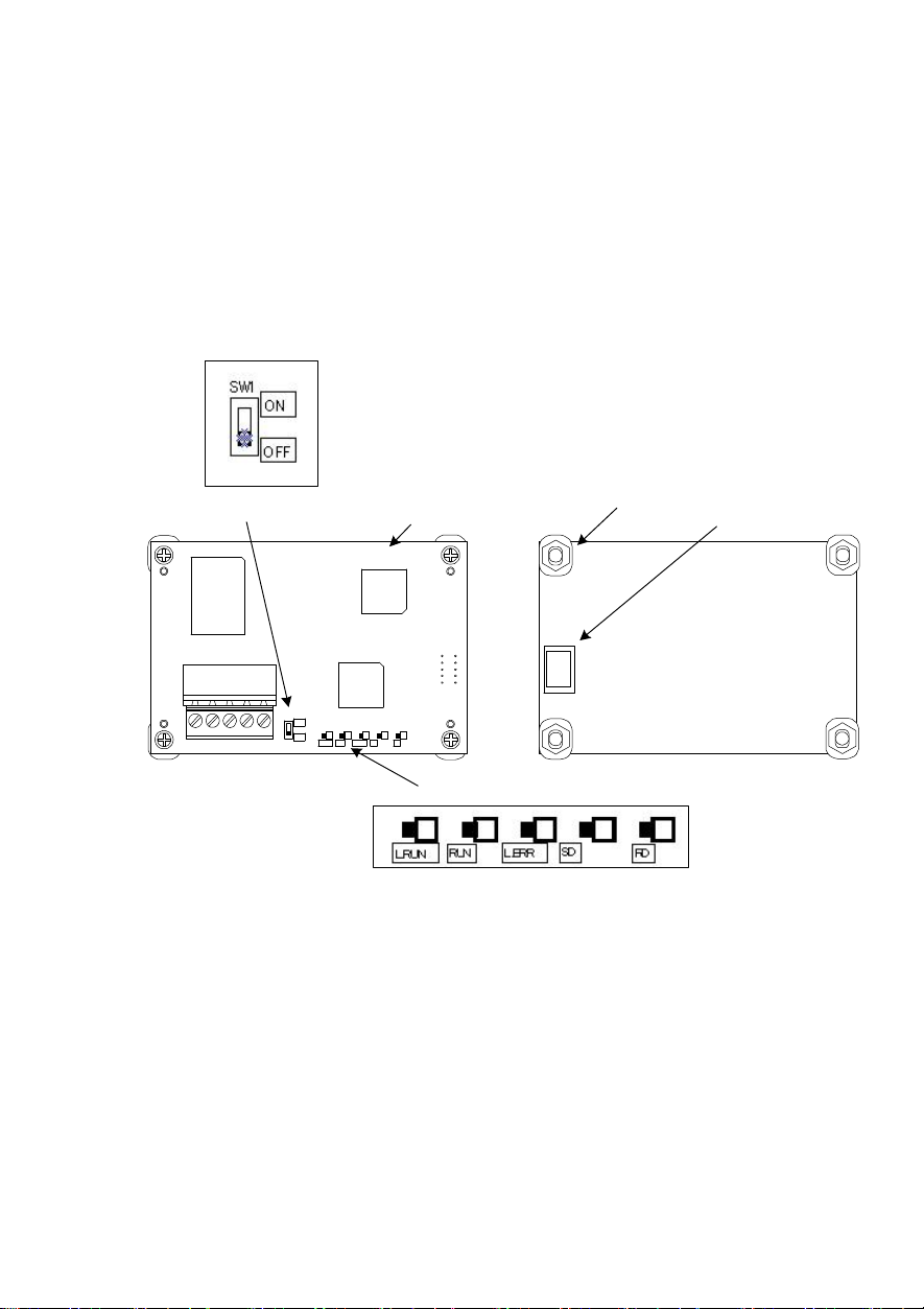
(3) The model name "OPC-F1-CCL" is printed on the DeviceNet Card. (See Figure 1.)
If you suspect the product is not working properly or if you ha ve any questions about your product, contact your Fuji
Electric representative.
This card corresponds to a soft version since 1300 of the FRENIC-Eco series inverters.
SW1(Terminating resistor selection swith)
Model number
Space(4)
CN1
OPC-F1-CCL
TB
1
SW
1
O
N
OF
F
L.RUNRUNL.ER
S
D
R
CN1
R
D
LED(Operation status indicator)
Figure1 Front of the Card Figure2 Back of the Card
4
Page 7
Control PCB
Chapter3 Installat ion
Turn the power off and wait for at least fi ve minutes for models of 30 kW or below, or ten minutes for models
of 37 kW or above, before starting installation. Further, check that the LED monitor is unlit, and check the DC
link circuit voltage between the P (+) and N (-) terminals to be lower than 25 VDC.
Otherwi se, elec tri c shoc k co uld oc cur.
Do not touch any metallic part of the connector for the main unit (CN1) or any electronic component.
Otherwise, electronic components may be damaged by static electricity. Also, the stain or adhesion of sweat
or dust may adversely affect the contact reliability of the connector in the long run.
An accid ent cou ld occ ur.
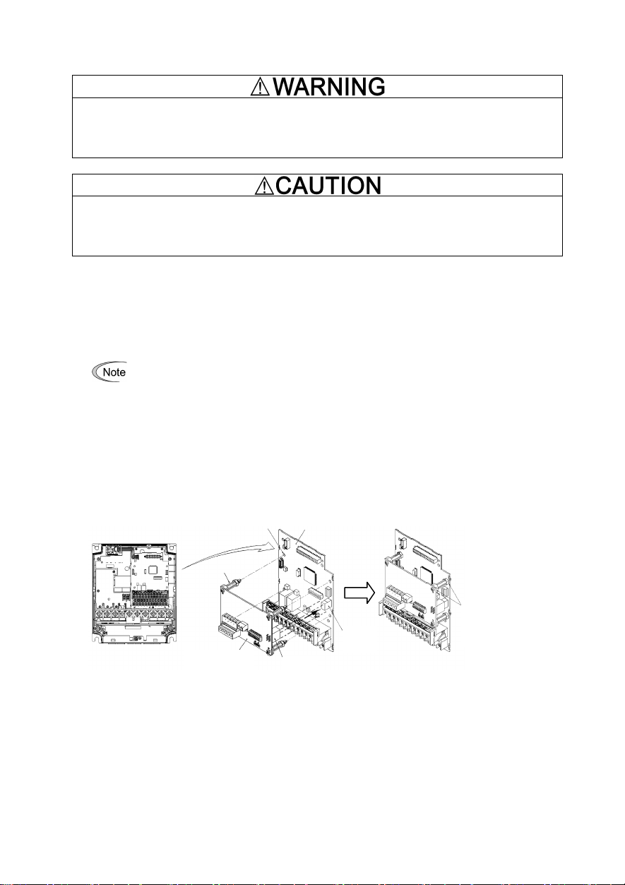
(1) Remove the covers from the inverter to expose the control printed circuit (Figure 3).
For the removal instructions, refer to the FRENIC-Eco Instruction Manual (INR-SI47-0852□), Chapter 2,
Section 2.3 "Wiring." (For ratings of 37 kW or above, also open the keypad enclosure.)
(2) Insert four spacers and connector CN1 on the back of the OPC-F1-CCL (Figure 2) into the four spacer holes and
Port A (CN4) on the inverter's control printed circuit board (PCB) (Figure 4), respectively.
Make sure, visually, that the spacers and CN1 are firmly inserted (Figure 5).
(3) Install the wires for the OPC-F1-CCL.
For wiring instructions, see Chapter 4.
(4) Put the covers back to its original position.
For the installation instructions, refer to the FRENIC-Eco Instruction Manual (INR-SI47-1059-E), Chapter 2,
Section 2.3 "Wiring." (For ratings of 37 kW or above, also close the keypad enclosure.)
4 Spacer Holes
Figure 3 FRN7.5F1S-2J -
FRN15F1S-2J
(example)
4 Spacers
Port A
CC-Link Card
OPC-F1-CCL
Figure 4 Mounting the Card Figure 5 Mounting Completed
CN1
(CN4)
5
Make sure that there
is no space between
control PCB and
spacers.
Page 8
DADBDG
SLD
FG
Motor
Power
DB
DB
DB
Chapter4 Wiring and Cabling
The
wiring and cabling diagram is shown on the page that follows. Observe the following precautions
when connecting the product.
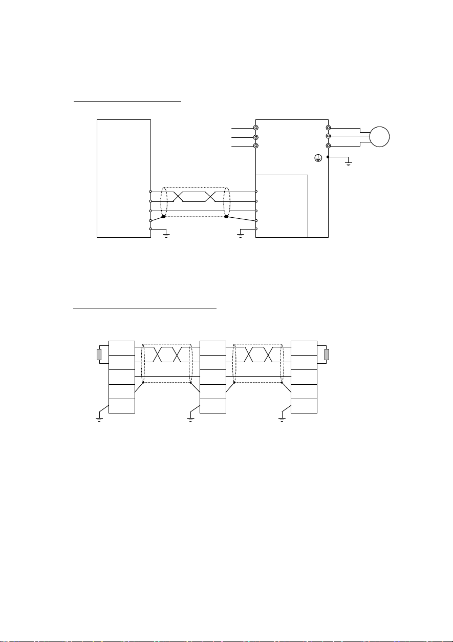
When one inverter is connected:
CC-Link Master
Shielded twist
pair cable
Eco inverter
R U
S V
T W
OPC-F1-CCL
DA
DB
DG
SLD
FG
Figure 6 Inverter connection diagram (One unit)
Set SW1 to ON(With terminating resistor).
When two or more inverters are connected:....... For the number of connected units, refer to chapter 14.
Master
DA
Terminal Terminal resistor
DG
SLD
FG
Shielded twist
pair cable
Eco
OPC-F1-CCL
inverter
DA
DG
SLD
FG
*1
Shielded twist
pair cable
Eco
OPC-F1-CCL
inverter
DA
DG
SLD
FG
(SW1=ON)
Figure 7 Inverter connection diagram (Two or more units)
*1) For the unit in the middle, set SW 1 to OFF(W ithout terminating resistor).
6
Page 9
g
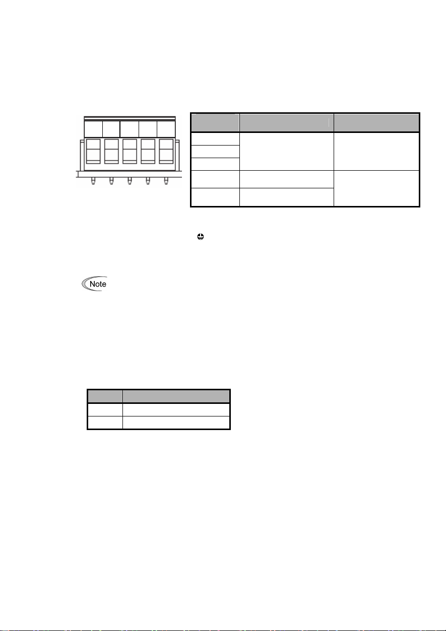
Figure 8
Terminal block TB1
[Precautions about connection]
(1) Use a special cable for the product. (Refer to chapter 14.)
Never use a soldered cable because it may cause disconnection or wire break.
(2)
Wiring around the
FG SLD DG DB DA
[Wiring around the grounding terminal (FG)]
Connecting the grounding terminal( G ) on the inverter.
Applicable wire size: AWG24~12(0.2mm2~2.5mm2)
Tightening torque : 0.5~0.6 [Nm]
For protection against external noise and prevention of failures, be sure to connect a groundin
wire.
A typical pluggable connector meeting the specifications is MSTB 2.5/5-ST-5.08-AU made by Phoeni x
Contacts.
CC-Link
pluggable connector
Table 1
Terminal
designation
DA
DB
DG
SLD
FG
Terminal board specifications
Description Remark
Used for comm unication
data
Used for connecting the
shield wire of the cable
Used for connecting the
earthing wire
The SLD and FG are
connected each other
in the unit.
(3)
Terminating resistor switch
By ON or OFF of SW1, internal terminating resistor can be set.
SW1 Description
OFF Without terminating resistor
ON 110Ω
(4) Use the terminating resistors supplied with the PLC.
(5) Please refer to connected number in Chapter 14 for the maximum, connected number.
(SW1)
7
Page 10
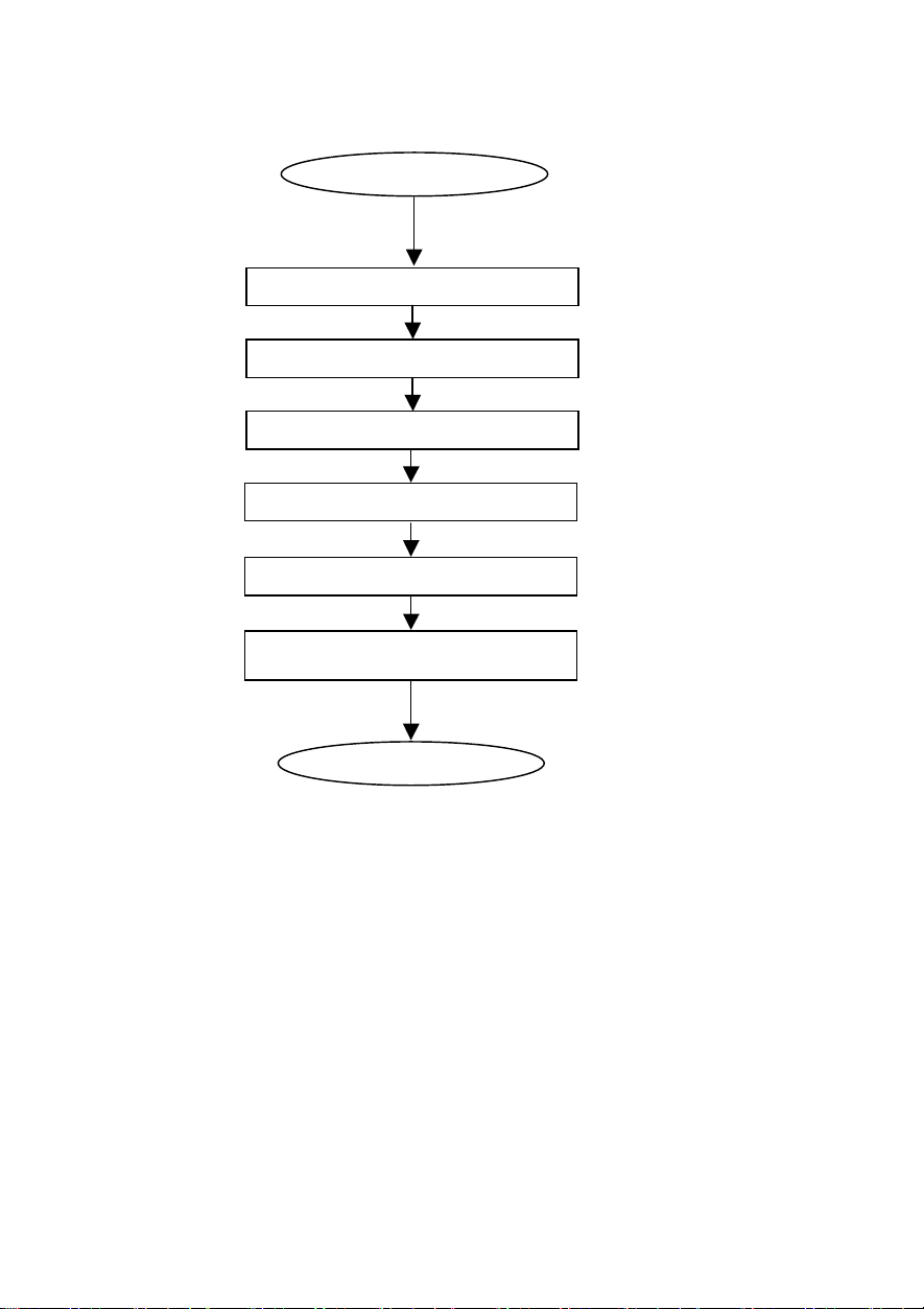
Chapter5 Procedure for In tr oducti on of the Option
The procedure for introducing CC-Link option is described here. Please prepare in the following steps:
Set the switches (SW1).
Turn ON the power to the inverters.
After the above steps have been done, the preparation for operating the inverters is complete.
Confirm the communication is normal after confirming the master side set with LED lit.
Refer to operation status indicate LED in Chapter 14 for lighting LED.
After the master side has been prepared, the inverters can be operated via CC-Link by setting RUN.
Start
Acceptance inspection
Install the option.
Connect the cables.
Set the function codes
(H30,y98,o27~o32).
Preparation finish
See “2. Acceptance Inspection”.
See “3. Installation”.
See “4. Wiring and Cabling”.
See “14 Specifications”.
See “6. Function Codes”, “7.
Protective Operation”,and “8.
Link Functions”.
8
Page 11
Chapter6 Function Codes
·If the data of a function code is incorrect, the system may fall into a dangerous status. Recheck data
whenever you have finished setting or writing data.An acciden t m ay oc cur.
6.1 Standard func tion codes
There are restrictions on the standard function codes that can be accessed from CC-Link. For further
information, refer to the Link No. in chapter 8
6.2 Functi on codes excl usive to communi cati on
A common data format (S-code, M-code, W -code, X-code and Z-code) can be used as the specifications
exclusive to communication. The data relating to the command / monitoring are difined other than the
standard function codes. For the details of the communication-exclusive function codes, refer to Chapter 5 of
FRENIC-Eco RS485 User’s Manual (MEH448). However, the following communication-exclusive function
codes prohibit writing via CC-Link (allows reading).
Table2 Communication-exclusive function codes that prohibit writing
No.
S01
S05 Frequency command
S06 Operation command
Function code name
Frequency command
(p.u.)
Because the same data can be written from the remote
output and the remote register. (Refer to “10.
Communication Specifications”.)
Reason
6.3 Functi on codes excl usive to the optio n
In the software exclusive to CC-Link option, the operations o27,o28 and o30 in addition to the standard
function codes, are available as the function codes exclusive to the option.
Table3 Function codes exclusive to the option
No. Function code name Setting range
Operation when a failure has
o27
occurred
Communication failure when
o28
a failure has occurred
Extended setting
o30
(Multiple setting)
CC-Link option
o31
station number setting
CC-Link option
Transmission Baud rate
o32
setting
For the details of the function code o27 and o28, refer to “7. Protective Operation”.
0~15 The operation when the error is detected is selected.
0.0~60.0sec
0,5~255
1 Occupying one station (CC-Link Ver.1.1)
2 Occupying one station double(CC-Link Ver.2)
3 Occupying one station quadrople(CC-Link Ver.2)
4 Occupying one station octuple(CC-Link Ver.2)
0~64
65~255 Invalidity
0 156kbps
1 625kbps
2 2.5Mbps
3 5Mbps
4 10Mbps
5~255 Invalidity
Time set by the timer for continuing operation if a
communication failure has occurred.
non operation
Sets station number (address)
(Setting value “0”is station number “1”.)
Setting if a failure has occurred
The underlined part is a factory setting value.
9
Page 12

Chapter7 Protecti ve Operation
7.1 Prot ective Operati on function codes
This section describes how to operate if a failure of communication line occurs when the system is being
operated by operation command and speed command given through the CC-Link.
(1)
The inverter operation to be performed if a CC-Link communication error occurs
o27
4~9
13-15 Operating is continued to the return of the
*1
Communication line failure factor:Tim e over error
*2
Setting value of transmission Baud rate setting (o32) is reflected at the reset input (RST) or next power
*3
The factory values are all "0".
Inverter Operation in the Event of an Error Note
0 Put the motor immediately in trip.
1
Immediately trip the inverter by force, when the
time set by o28 (Timer) has expired.
2 Operating is continued to the return of the
communication according to the last command. If
the communication doesn't return to the end at
the time of the tim er of o28, the compulsion trip
mode.
3 Operating is continued to the return of the
communication, and after it returns,
it follows the instruction in the communication.
Same as for [o27=0]
10 Immediately decelerate the motor by force. When
the motor has stopped, turn on er5.
11 When the time set by o28 (Timer) has expired,
immediately decelerate the motor by force, when
the motor has stopped, turn on er5 .
12 Operating is continued to the return of the
communication according to the last command.
After decelerate the motor by force, turn on er5,
if the communication doesn't return to the end at
the time of the timer of o28.
communication, and after it returns,
it follows the instruction in the communication.
Option failure:W hen the MFP3 access error or the main body of the inverter and the communication error
occurs, Er4 is generated. It doesn't relate to the setting value of o27.
supply ON.
Automatic
return after
communication
returns
Automatic
return after
communication
returns
(o27).
The forced deceleration
period is specified by
F08.
10
Page 13
operation of
If transmission error occurs during acceleration, the speed
operation of
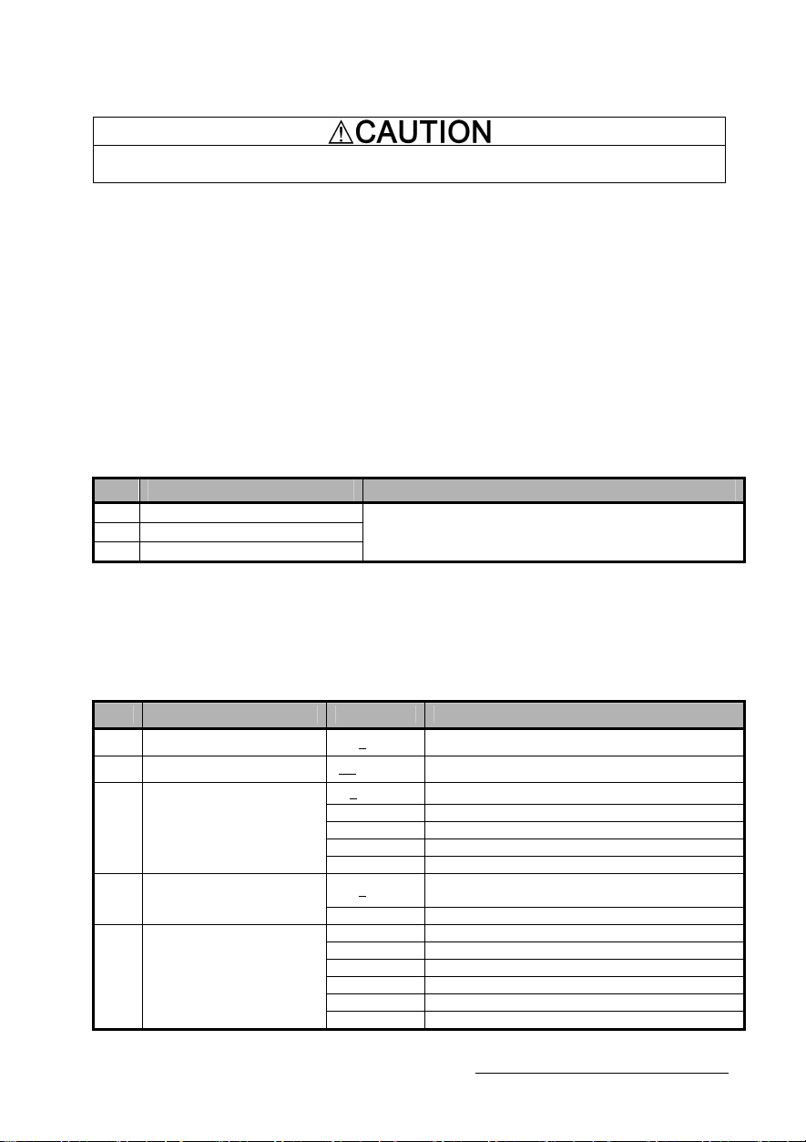
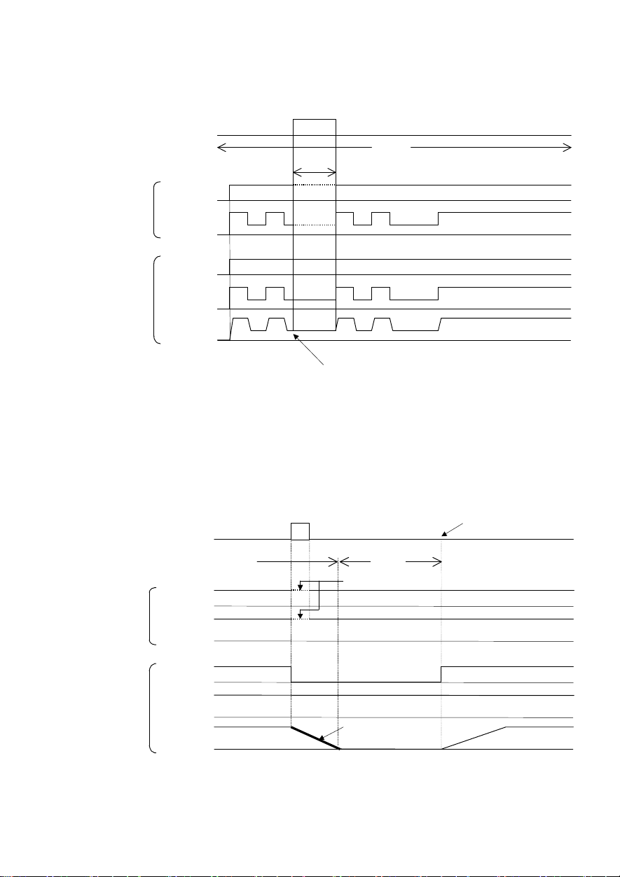
(2) Communication failure when a failure has occurred (o28)
0.0~60.0 sec
●
When the function code
o27=0 (
Mode in which the inverter is forced to immediately in trip in case of
communication failure
Command
from master
Communication
status
Indication
FWD
Setting up
frequency
Normal
Normal
ON
Error
Communic ation error
)
Normal
Er 5
ON
Alarm reset
Internal
Inverter
●
When the function code
Communication
Indication
FWD
Setting up
frequency
Operation
command
Setting up
frequency
Output
frequency
Command
from master
Internal
Inverter
Operation
command
Setting up
frequency
Output
frequency
o27=1 and o28=5.0 (
status
Normal
Operation
Normal
※11
ON
Operation
Stop
Free-run
Operation
Mode in which the inverter is forced to stop five seconds after a
communication failure occurred
Error
Normal
Er 5
5.0s
OFF
Stop
Free-run
)
Alarm reset
ON
Operation
accelerates up to the setting up f requency
11
Page 14
operation of
Indication
operation of
sion error occurs during acceleration, the
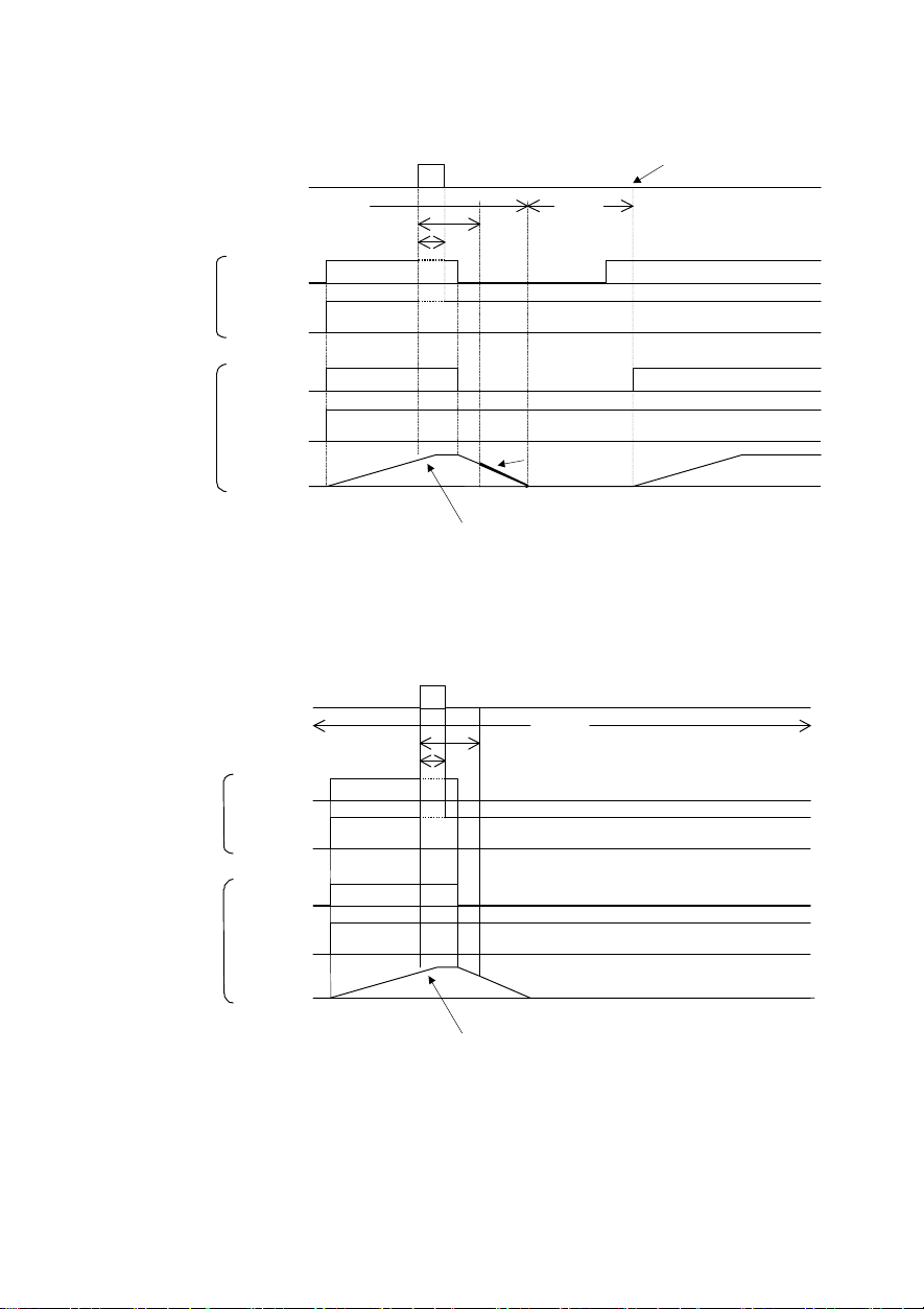
●
When the function code
Command
from master
Communication
FWD
Setting up
frequency
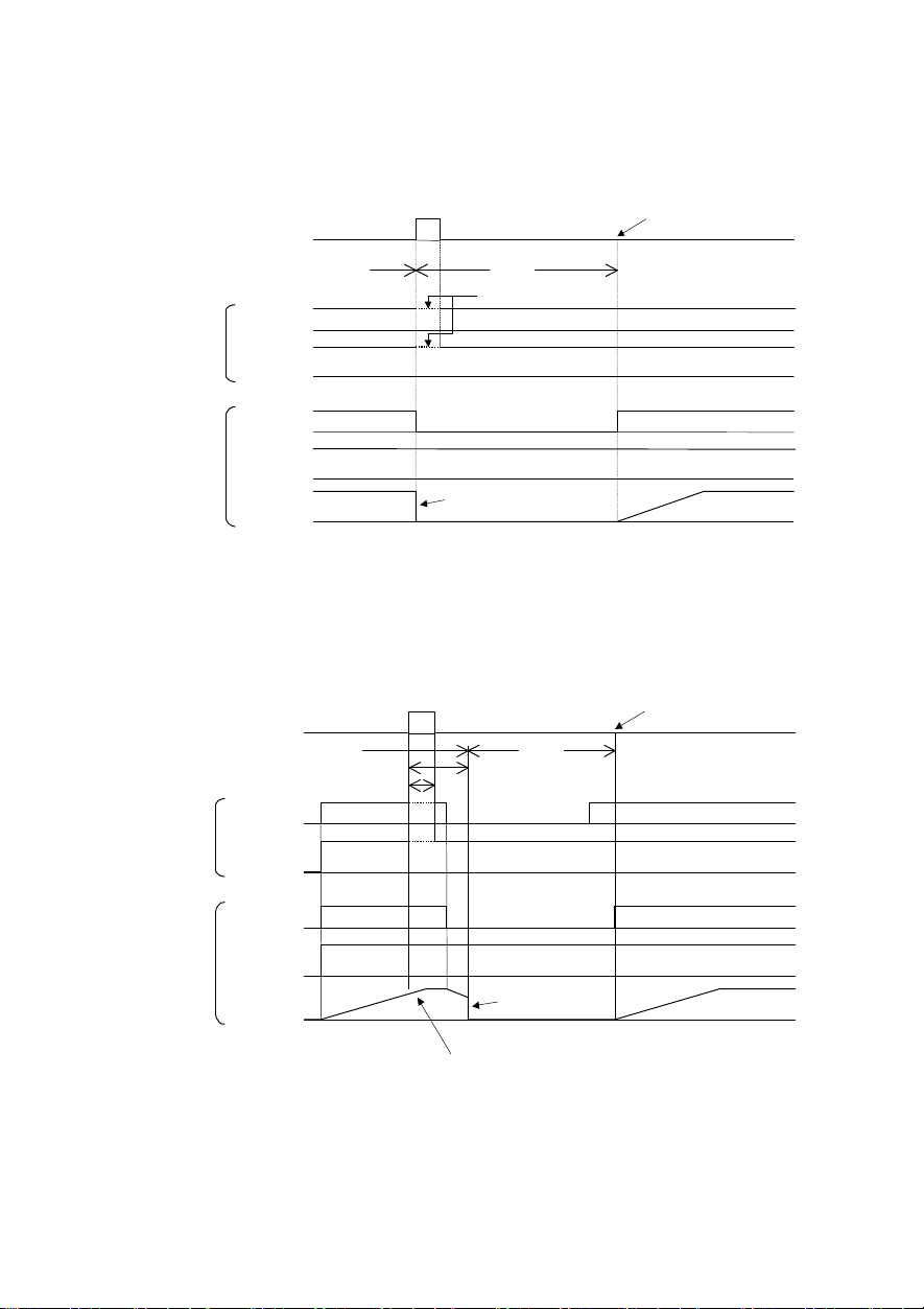
o27=2 and o28=5.0 (
When c ommunications is not recovered although five seconds
elapsed from the occurrence of a communications failure , and an er8 trip
occurs
)
status
Normal
Normal
ON
5.0 s
Error
Normal
※11
Alarm reset
Er 5
ON
Operatio n
command
Internal
Inverter
Setting up
frequency
frequency
※11
For the period until communications is recovered, the command (command data, operation
data) executed just before the communications failure had occurred is retained.
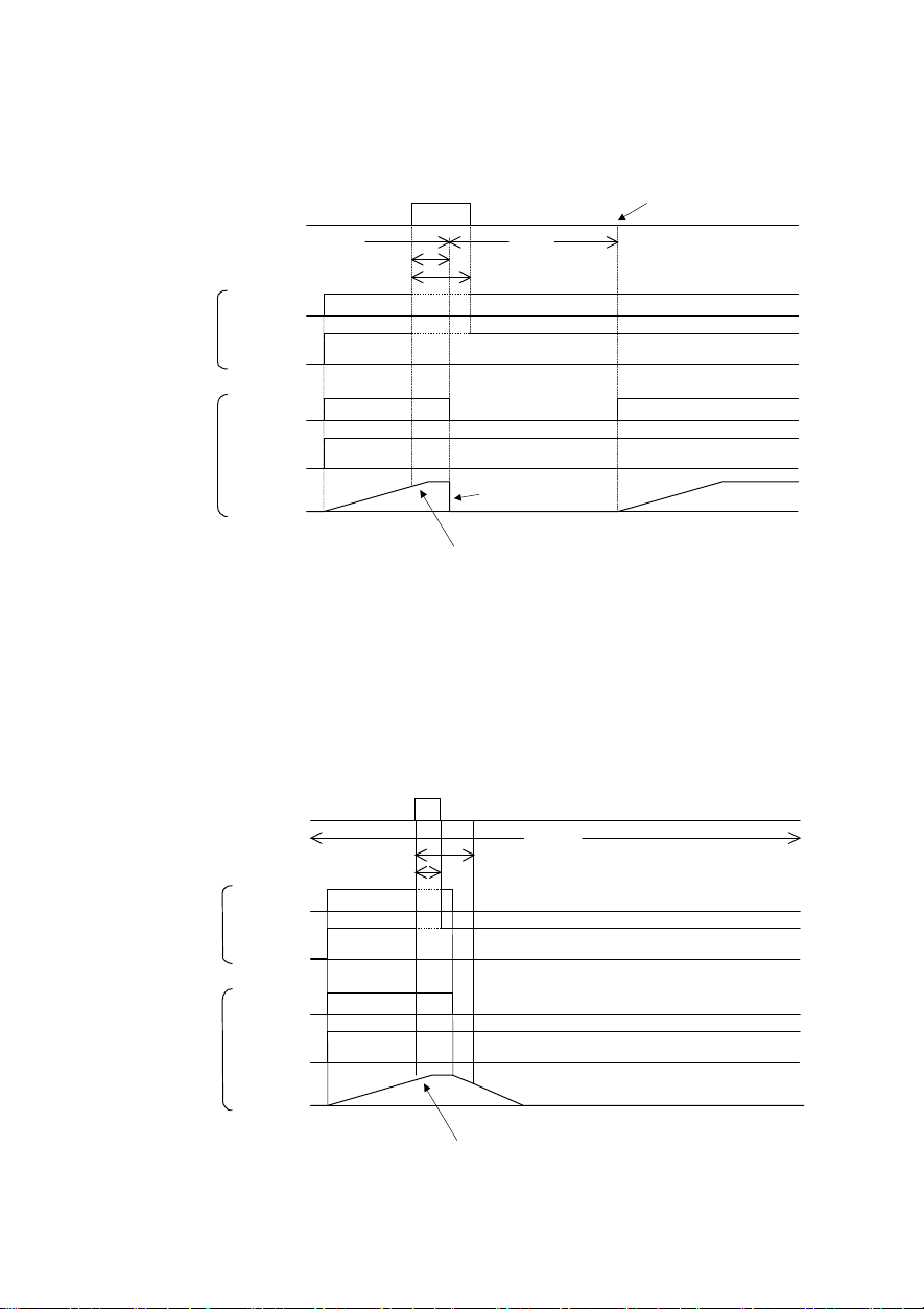
●
When the function code
Command
from master
Internal
Inverter
Communication
FWD
Operation
command
Setting up
frequency
frequency
Output
o27=2 and o28=5.0 (
status
Indication
Setting up
frequency
Output
Operation
Normal
※11
ON
Operation
Stop
Free-run
If transmission error occurs during acceleration, the
speed accelerates up to the setting up frequency
Operation
When a communications failure occurred but communications
was recovered within five seconds
Error
Normal
Normal
5.0s
OFF
Stop
If transmis
speed accelerates up to the set ting up frequency
12
)
Page 15
ON
operation of
Communication
of transm ission error is held
operation of
Setting up
●
When the function code
Indication
Command
from master
FWD
Setting up
frequency
o27=3,13 ~ 15 (
status
Mode in which the inverter continues operating when a
communication failure occurs
Error
Normal
ON
)
Normal
Normal
※11
Operation
command
Internal
Inverter
Setting up
frequency
Output
frequency
※11
For the period until communications is recovered, the command (command data, operation
data) executed just before the communications failure had occurred is retained.
●
When the function code
Command
from master
Communication
Indication
FWD
frequency
status
Operation
o27=10 (
Mode in which the inverter is forced to immediately stop when a
communication failure occurs
Normal
Normal
ON
Error
The stting at the time
on and the operation continues.
)
Normal
Er 5
Communication error
ON
Alarm reset
Internal
Inverter
Operation
command
Setting up
frequency
Output
frequency
Operation
Stop
Decelerate the motor by force
(
Deceleration time is by F08.
13
Operation
)
Page 16
If transmission error occurs during acceleration, the
operation of
11
operation of
frequency
●
When the function code
Command
from master
Communication
Indication
FWD
Setting up
frequency
o27=11 and o2 8=5.0 (
status
Normal
Normal
ON
Mode in which the inverter is forced to stop in 5 sec onds
when a communication failure occurs
Error
Normal
※11
5.0s
Er 5
OFF
)
Alarm reset
ON
Operation
command
Internal
Inverter
Setting up
frequency
frequency
●
When the function code
Command
from master
Internal
Invert er
Communication
FWD
Operation
command
Setting up
frequency
frequency
Output
o27=12 and o28=5.0 (
status
Indication
Setting up
Output
Operation
Normal
※
ON
Operation
Stop
Decelerate the motor by force
(
Deceleration time is by F08.
speed accelerates up to the setting up frequency
Operation
)
Mode in which the communication returned within five seconds,
when a communication failure occurs
Error
Normal
Normal
5.0s
OFF
Stop
If transmission error occurs during acceleration, the
speed accelerates up to the setting up frequency
)
14
Page 17
S codes (command data, operation data) can be
Chapter8 Li nk Functions
The function code y98 “Bus Link function (Mode selection)” and the X function “24: operation selection through link
[LE]” switch the validity (REM · LOC/COM) of command data (S area). Familiarize yourself with it together with the
control block (Chapter 4 in the FRENIC-Eco User’s Manual (MET456)).
8.1 Enabling li nk operatio n
When the inverter is operated through the CC-Link, the operation must be switched to “Operation through link
enable” mode and “command through communication (other than 0)” must be selected by y98 “ Bus Link function
(Mode selection)”. (Such a flexible system configuration as operation command sent from the terminal board and
speed command sent through communication is enabled by selecting the value of y98 “Bus Link function (Mode
selection)”.)
Con ditio n Mod e
Command code FBH
(operation mode) = 0
Command code FBH
(operation mode) = 1
Corresponding X terminal ON “Operation through link
Corresponding X terminal OFF “Operation through link
Assigning “24 : operation
selection through link [LE]” to
E01~E05 “X function selection”
Not
assigned
Assigned
y98 set ti ng
val ue
0
1
2
3
“ Oper atio n t hroug h link enable” mode “ Operat ion thro ugh li nk d isable” mo de
Com mand data
× × ×
○ × ×
× ○ ×
○ ○ ×
Operat io n
comman d
Com mand data
:Command through communication is valid. ×:Command through communication is invalid (Operation is
enabled by the command from the terminal board or the keypad.)
Even in “Operation through link disable” mode,
written.
8.2 Confir mation and writing of funct ion code
The change (writing) and the confirmation (reading) in the function code from CC-Link are always effective.
15
“Operation through link
enable” mode
“Operation through link
disable” mode
enable” mode
disable” mode
Operat io n co mm and
Page 18
read
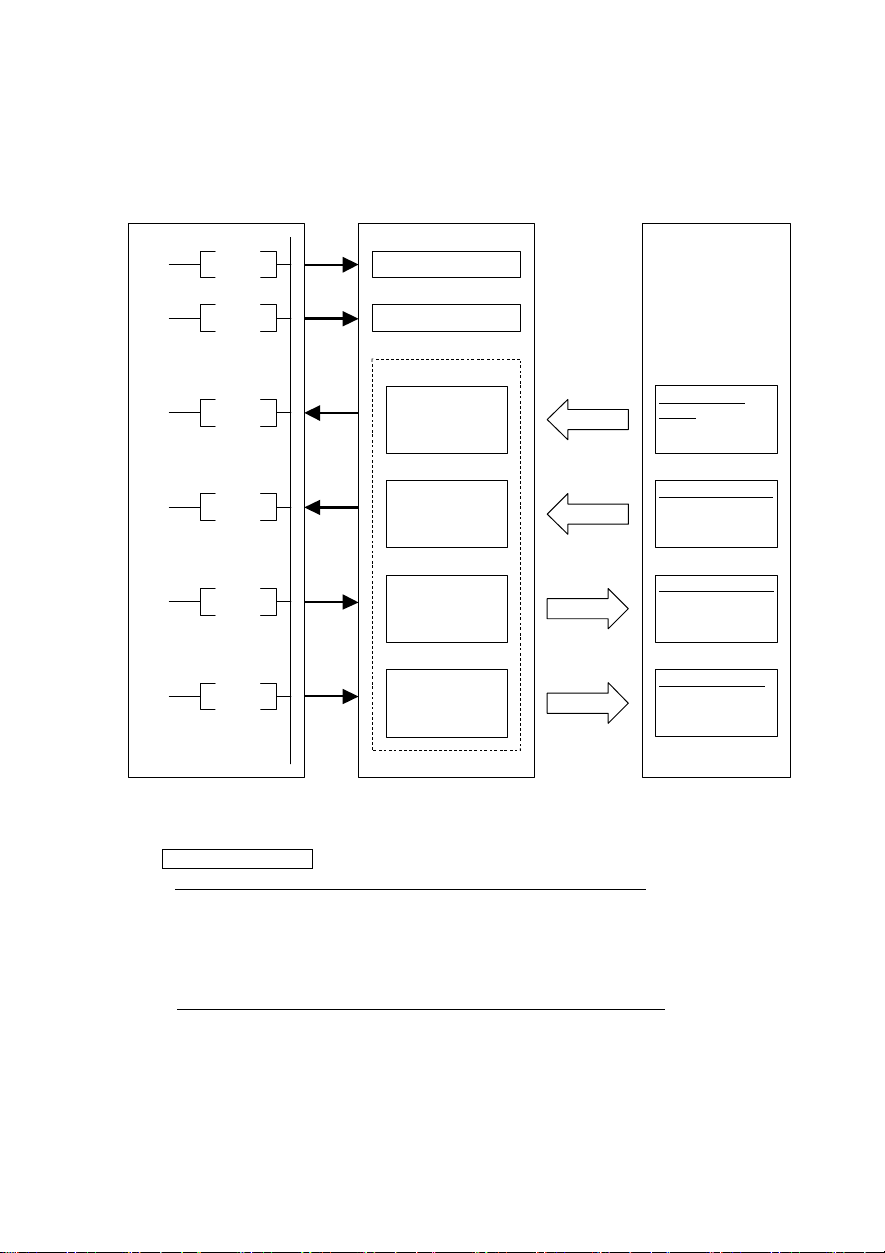
Chapter9 Com munication between Sequencer
9.1 Outline of t he co mmu nication
Sequencer CPU
SET Yn0
CC-Link
master unit
Refresh command
Eco Inverter
SET Yn6
FROM
FROM
TO
TO
Data link start
Buffer memory
Remote input
(RX)
Remote register
(RWr)
Remote output
(RY)
Remote register
(RWw)
Link scan
Control signal
output
· Inverter status
Control data output
· Monitor
· Function code
Control signal input
· Operation
command
Control data i nput
· Speed command
· Function code
write
Figure 9
CC-Link master station
(1) CPU with automatic refresh function installed (Example: QnA-CPU)
Communication between the CC-Link master station and the remote device is performed by
exchanging data through the sequence ladder and by autom atically refreshing the refresh
buffer of the master station with END command.
(2) CPU without automatic refresh function installed (Example: AnA-CPU)
Communication between the CC-Link master station and the remote device is performed by
exchanging data directly with the refresh buffer of the master station through the sequence
ladder.
16
Page 19

9.2 Reliability of data exc hang ed thro ugh link
· Consistency between the bit data and word data exchanged through link is established by the data
configuration in which bit data of different timing from word data can not be included in a word data
when bit data changes.
· The buffer operation commands of master unit (FROM, TO), different from normal inputs/outputs, are
not updated in batch, but processed through interrupt during execution of the program. The
input/output operation through link are executed at the timing of the command. So, note the following
three points:
(1) Execute data acquisition by FROM command at the start of the program.
(2) Execute update of output by TO comm and after all the related internal processing has finished.
(3) Execute update of output buffers of a unit at a same time (in one row).
It is recommended that all the link buffers are updated in batch.。
17
Page 20

9.3 Usin g area of bu ffer memory
(1)
Remote input signal (Inverter Master)
Mas ter s tation Rem ote dev ice s tatio n Rem ote dev ice sta tion
no. 1
For stati on
no. 2
For stati on
no. 3
For stati on
no. 63
For stati on
no. 64
Ad dress Rem ote in put
00E 0H R X 0 ~ RX F
00E 1H RX 1 0 ~ RX 1F RX 10 ~ RX 1F
00E 2H RX 2 0 ~ RX 2F
00E 3
00E 4H RX 4 0 ~ RX 4F RX 0 ~ RX F
00E 5
015 CH RX 7C0 ~ R X 7CF
015 D
015 EH RX 7E0 ~ R X 7EF
015 F
H
H
~
H
H
RX 30 ~ RX 3F
RX 50 ~ RX 5F
RX 7D0 ~ R X 7DF
RX 7F0 ~ R X 7FF
~
(2)
Remote output signal (Master Inverter)
Mas ter sta tion Rem ote dev ice st ation R emo te de vice s tation
no. 1
For statio n
no. 2
For statio n
no. 3
For statio n
no. 63
For statio n
no. 64
Ad dress Rem ote in put
01 60H R Y 0 ~ R Y F
01 61H RY 1 0 ~ RY 1 F RY 1 0 ~ RY 1F
01 62H RY 2 0 ~ RY 2 F
01 63
01 64H RY 4 0 ~ RY 4 F R Y 0 ~ RY F
01 65
01 DCH RY 7C0 ~ RY 7CF
01 DD
01 DEH RY 7E0 ~ RY 7EF
01 DF
H
H
~
H
H
RY 30 ~ RY 3F
RY 50 ~ RY 5F
RY 7D0 ~ RY 7DF
RY 7F0 ~ RY 7FF
~
(3)
Remote register (Master Inverter)
For station
no. 1
For station
no. 2
For station
no. 3
For station
no. 64
Mas ter sta tion Rem ote dev ic e st ation Rem ote dev ice stat ion
Add ress
01E 0H RWw 0 RWw 0
01E 1H RWw 1 RWw 1
01E 2H RWw 2 RWw 2
01E 3H RWw 3 RWw 3
01E 4H RWw 4 RWw 0
01E 5
01E 6H RWw 6 RWw 2
01E 7H RWw 7 RWw 3
01E 8H RWw 8 RWw 4
01E 9H RWw 9 RWw 5
01E AH RWw A RWw 6
01E BH RWw B RWw 7
02D CH RWw F C
02D DH RWw FD
02D EH RWw F E
02D FH RWw FF
Rem ote inp ut
H
~
RWw 5
~
Stat ion no .1: one statio n occ upied Stati on no .3: one stati on occ upied
RX 10 ~ RX 1F
RX 0 ~ RX F
For stati on
Figure 10
Stati on no .1: one stati on occ upied Stati on no. 3: one statio n occ upied
RY 1 0 ~ RY 1F
RY 0 ~ RY F
For statio n
Figure 11
Statio n no.1: one station oc cupied S tation no .2: one station o ccupied
RWw 1
Figure 12
/ d ouble
18
Page 21

(4)
Remote register (Inverter Master)
Mas ter st ation Re mot e dev ice st ation Remo te de vice stat ion
For statio n
no. 1
For statio n
no. 2
For statio n
no. 3
For statio n
no. 64
Add ress
02 E0H RWr 0
02 E1H RWr 1 RW r 1
02 E2H RWr 2 RW r 2
02 E3
H
02 E4H RWr 4 RW r 0
02 E5H RWr 5 RW r 1
02 E6H RWr 6 RW r 2
02 E7H RWr 7 RW r 3
02 E8H RWr 8 RW r 4
02 E9H RWr 9 RW r 5
02 EAH RWr A RW r 6
02 EBH RWr B RW r 7
~
03 DCH RWr FC
03 DDH RWr FD
03 DEH RWr FE
03 DFH RWr FF
Rem ote in put
RWr 3
~
9.4 Usin g add resses of buffer memo ry
Table 4 Conversion formula of buffer memory address
Master
CPU with automatic refresh
function installed (QnA type)
CPU without automatic refresh
function installed (AnA type)
Register no.
Address Buffer memory top address
Table 5 Buffer m emory address assignment
Station
Input (Inverter Master) Output (Master Inverter)
no.
Register no. Address Register no. Address Register no. Address Register no. Address
1 RX 0~RX 1F 00E0H~00E1
2 RX 20~ RX 3F 00E2H~00E3
3 RX 40~ RX 5F 00E4H~00E5
4 RX 60~ RX 7F 00E6H~00E7
5 RX 80~ RX 9F 00E8H~00E9
6 RX A0~ RX BF 00EAH~00EB
7 RX C0~ RX DF 00ECH~00ED
8 RX E0~ RX FF 00EEH~00EF
9 RX100~ RX11F 00F0H~00F1
10 RX12 0~RX13F 00F2H~00F3
11 RX14 0~RX15F 00F4H~00F5
12 RX16 0~RX17F 00F6H~00F7
13 RX18 0~RX19F 00F8H~00F9
14 RX1A 0~RX1BF 00FAH~00FB
15 RX1C 0~RX1DF 00FCH~00FD
16 RX1E 0~RX1FF 00FEH~00FF
17 RX20 0~RX21F 0100H~0101
18 RX22 0~RX23F 0102H~0103
19 RX24 0~RX25F 0104H~0105
20 RX26 0~RX27F 0106H~0107
21 RX28 0~RX29F 0108H~0109
Remote input/output signal Remote register
H
H
H
H
H
H
H
H
H
H
H
H
H
H
H
H
H
H
H
H
H
RY 0~RY 1F 0160H~0161
RY 20~ RY 3F 0162H~0163
RY 40~ RY 5F 0164H~0165
RY 60~ RY 7F 0166H~0167
RY 80~ RY 9F 0168H~0169
RY A0~ RY BF 016AH~016B
RY C0~ RY DF 016CH~016D
RY E0~ RY FF 016EH~016F
RY100~ RY11F 0170H~0171
RY120~ RY13F 0072H~0173
RY140~ RY15F 0074H~0175
RY160~ RY17F 0076H~0177
RY180~ RY19F 0078H~0179
RY1A0~ RY1BF 007AH~017B
RY1C0~ RY1DF 007CH~017D
RY1E0~ RY1FF 007EH~017F
RY200~ RY21F 0180H~0181
RY220~ RY23F 0182H~0183
RY240~ RY25F 0184H~0185
RY260~ RY27F 0186H~0187
RY280~ RY29F 0188H~0189
Statio n no.1: one station occu pied Sta tion n o.2: occ uping one s tation d ouble
RWr 3
RWr 0
Figure 13
Conversion formula
(Derive register number divided by buffer memory address
from station no.)
Remote input/output signal
Remote register
(Station no.-1) 20H (Station no.-1) 4H
Buffer memory top address
+(station no.-1) 2H
Master Inverter Inverter Master
RWw 0~ RWw 3 01E0H~01E3
H
RWw 4~ RWw 7 01E4H~01E7
H
RWw 8~ RWw B 01E8H~01EB
H
RWw C~ RWw F 01ECH~01EF
H
RWw10~ RWw13 01F0H~01F3
H
RWw14~ RWw17 01F4H~01F7
H
RWw18~ RWw1B 01F8H~01FB
H
RWw1C~ RWw1F 01FCH~01FF
H
RWw20~ RWw23 0200H~0203
H
RWw24~ RWw27 0204H~0207
H
RWw28~ RWw2B 0208H~020B
H
RWw2C~ RWw2F 020CH~020F
H
RWw30~ RWw33 0210H~0213
H
RWw34~ RWw37 0214H~0217
H
RWw38~ RWw3B 0218H~021B
H
RWw3C~ RWw3F 021CH~021F
H
RWw40~ RWw43 0220H~0223
H
RWw44~ RWw47 0224H~0227
H
RWw48~ RWw4B 0228H~022B
H
RWw4C~ RWw4F 022CH~022F
H
RWw50~ RWw53 0230H~0233
H
+(station no.-1) 4H
RWr 0~ RWr 3 02E0H~02E3
H
RWr 4~ RWr 7 02E4H~02E7
H
RWr 8~ RWr B 02E8H~02EB
H
RWr C~ RWr F 02ECH~02EF
H
RWr10~ RWr13 02F0H~02F3
H
RWr14~ RWr17 02F4H~02F7
H
RWr18~ RWr1B 02F8H~02FB
H
RWr1C~ RWr1F 02FCH~02FF
H
RWr20~ RWr23 0300H~0303
H
RWr24~ RWr27 0304H~0307
H
RWr28~ RWr2B 0308H~030B
H
RWr2C~ RWr2F 030CH~030F
H
RWr30~ RWr33 0310H~0313
H
RWr34~ RWr37 0314H~0317
H
RWr38~ RWr3B 0318H~031B
H
RWr3C~ RWr3F 031CH~031F
H
RWr40~ RWr43 0320H~0323
H
RWr44~ RWr47 0324H~0327
H
RWr48~ RWr4B 0328H~032B
H
RWr4C~ RWr4F 032CH~032F
H
RWr50~ RWr53 0330H~0333
H
H
H
H
H
H
H
H
H
H
H
H
H
H
H
H
H
H
H
H
H
H
19
Page 22

Station no.
Input (Inverter Master) Output (Master Inverter)
Register no. Address Register no. Address Register no. Address Register no. Address
22 R X2A0~RX2BF 010AH~010B
23 R X2C0~RX2DF 010CH~010D
24 R X2E0~RX2FF 010EH~010F
25 R X300~RX31F 0110H~0111
26 R X320~RX33F 0112H~0113
27 R X340~RX35F 0114H~0115
28 R X360~RX37F 0116H~0117
29 R X380~RX39F 0118H~0119
30 R X3A0~RX3BF 011AH~011B
31 R X3C0~RX3DF 011CH~011D
32 R X3E0~RX3FF 011EH~011F
33 R X400~RX41F 0120H~0121
34 R X420~RX43F 0122H~0123
35 R X440~RX45F 0124H~0125
36 R X460~RX47F 0126H~0127
37 R X480~RX49F 0128H~0129
38 R X4A0~RX4BF 012AH~012B
39 R X4C0~RX4DF 012CH~012D
40 R X4E0~RX4FF 012EH~012F
41 R X500~RX51F 0130H~0131
42 R X520~RX53F 0132H~0133
43 R X540~RX55F 0134H~0135
44 R X560~RX57F 0136H~0137
45 R X580~RX59F 0138H~0139
46 R X5A0~RX5BF 013AH~013B
47 R X5C0~RX5DF 013CH~013D
48 R X5E0~RX5FF 013EH~013F
49 R X600~RX61F 0140H~0141
50 R X620~RX63F 0142H~0143
51 R X640~RX65F 0144H~0145
52 R X660~RX67F 0146H~0147
53 R X680~RX69F 0148H~0149
54 R X6A0~RX6BF 014AH~014B
55 R X6C0~RX6DF 014CH~014D
56 R X6E0~RX6FF 014EH~014F
57 R X700~RX71F 0150H~0151
58 R X720~RX73F 0152H~0153
59 R X740~RX75F 0154H~0155
60 R X760~RX77F 0156H~0157
61 R X780~RX79F 0158H~0159
62 R X7A0~RX7BF 015AH~015B
63 R X7C0~RX7DF 015CH~015D
64 R X7E0~RX7FF 015EH~015F
Remote input/output signal Remote register
Master Inverter Inverter Master
RY2A0~RY2BF 018AH~018B
H
RY2C0~RY2DF 018CH~018D
H
RY2E0~RY2FF 018EH~018F
H
RY300~RY31F 0190H~0191
H
RY320~RY33F 0192H~0193
H
RY340~RY35F 0194H~0195
H
RY360~RY37F 0196H~0197
H
RY380~RY39F 0198H~0199
H
RY3A0~RY3BF 019AH~019B
H
RY3C0~RY3DF 019CH~019D
H
RY3E0~RY3FF 019EH~019F
H
RY400~RY41F 01A0H~01A1
H
RY420~RY43F 01A2H~01A3
H
RY440~RY45F 01A4H~01A5
H
RY460~RY47F 01A6H~01A7
H
RY480~RY49F 01A8H~01A9
H
RY4A0~RY4BF 01AAH~01AB
H
RY4C0~RY4DF 01ACH~01AD
H
RY4E0~RY4FF 01AEH~01AF
H
RY500~RY51F 01B0H~01B1
H
RY520~RY53F 01B2H~01B3
H
RY540~RY55F 01B4H~01B5
H
RY560~RY57F 01B6H~01B7
H
RY580~RY59F 01B8H~01B9
H
RY5A0~RY5BF 01BAH~01BB
H
RY5C0~RY5DF 01BCH~01BD
H
RY5E0~RY5FF 01BEH~01BF
H
RY600~RY61F 01C0H~01C1
H
RY620~RY63F 01C2H~01C3
H
RY640~RY65F 01C4H~01C5
H
RY660~RY67F 01C6H~01C7
H
RY680~RY69F 01C8H~01C9
H
RY6A0~RY6BF 01CAH~01CB
H
RY6C0~RY6DF 01CCH~01CD
H
RY6E0~RY6FF 01CEH~01CF
H
RY700~RY71F 01D0H~01D1
H
RY720~RY73F 01D2H~01D3
H
RY740~RY75F 01D4H~01D5
H
RY760~RY77F 01D6H~01D7
H
RY780~RY79F 01D8H~01D9
H
RY7A0~RY7BF 01DAH~01DB
H
RY7C0~RY7DF 01DCH~01DD
H
RY7E0~RY7FF 01DEH~01DF
H
RWw54~RWw57 0234H~0237
H
RWw58~RWw5B 0238H~023B
H
RWw5C~RWw5F 023CH~023F
H
RWw60~RWw63 0240H~0243
H
RWw64~RWw67 0244H~0247
H
RWw68~RWw6B 0248H~024B
H
RWw6C~RWw6F 024CH~024F
H
RWw70~RWw73 0250H~0253
H
RWw74~RWw77 0254H~0257
H
RWw78~RWw7B 0258H~025B
H
RWw7C~RWw7F 025CH~025F
H
RWw80~RWw83 0260H~0263
H
RWw84~RWw87 0264H~0267
H
RWw88~RWw8B 0268H~026B
H
RWw8C~RWw8F 026CH~026F
H
RWw90~RWw93 0270H~0273
H
RWw94~RWw97 0274H~0277
H
RWw98~RWw9B 0278H~027B
H
RWw9C~RWw9F 027CH~027F
H
RWwA0~RWwA3 0280H~0283
H
RWwA4~RWwA7 0284H~0287
H
RWwA8~RWwAB 0288H~028B
H
RWwAC~RWwAF 028CH~028F
H
RWwB0~RWwB3 0290H~0293
H
RWwB4~RWwB7 0294H~0297
H
RWwB8~RWwBB 0298H~029B
H
RWwBC~RWwBF 029CH~029F
H
RWwC0~RWwC3 02A0H~02A3
H
RWwC4~RWwC7 02A4H~02A7
H
RWwC8~RWwCB 02A8H~02AB
H
RWwCC~RWwCF 02ACH~02AF
H
RWwD0~RWwD3 02B0H~02B3
H
RWwD4~RWwD7 02B4H~02B7
H
RWwD8~RWwDB 02B8H~02BB
H
RWwDC~RWwDF 02BCH~02BF
H
RWwE0~RWwE3 02C0H~02C3
H
RWwE4~RWwE7 02C4H~02C7
H
RWwE8~RWwEB 02C8H~02CB
H
RWwEC~RWwEF 02CCH~02CF
H
RWwF0~RWwF3 02D0H~02D3
H
RWwF4~RWwF7 02D4H~02D7
H
RWwF8~RWwFB 02D8H~02DB
H
RWwFC~RWwFF 02DCH~02DF
H
RWr54~RWr57 0334H~0337
H
RWr58~RWr5B 0338H~033B
H
RWr5C~RWr5F 033CH~033F
H
RWr60~RWr63 0340H~0343
H
RWr64~RWr67 0344H~0347
H
RWr68~RWr6B 0348H~034B
H
RWr6C~RWr6F 034CH~034F
H
RWr70~RWr73 0350H~0353
H
RWr74~RWr77 0354H~0357
H
RWr78~RWr7B 0358H~035B
H
RWr7C~RWr7F 035CH~035F
H
RWr80~RWr83 0360H~0363
H
RWr84~RWr87 0364H~0367
H
RWr88~RWr8B 0368H~036B
H
RWr8C~RWr8F 036CH~036F
H
RWr90~RWr93 0370H~0373
H
RWr94~RWr97 0374H~0377
H
RWr98~RWr9B 0378H~037B
H
RWr9C~RWr9F 037CH~037F
H
RWrA0~RWrA3 0380H~0383
H
RWrA4~RWrA7 0384H~0387
H
RWrA8~RWrAB 0388H~038B
H
RWrAC~RWrAF 038CH~038F
H
RWrB0~RWrB3 0390H~0393
H
RWrB4~RWrB7 0394H~0397
H
RWrB8~RWrBB 0398H~039B
H
RWrBC~RWrBF 039CH~039F
H
RWrC0~RWrC3 03A0H~03A3
H
RWrC4~RWrC7 03A4H~03A7
H
RWrC8~RWrCB 03A8H~03AB
H
RWrCC~RWrCF 03ACH~03AF
H
RWrD0~RWrD3 03B0H~03B3
H
RWrD4~RWrD7 03B4H~03B7
H
RWrD8~RWrDB 03B8H~03BB
H
RWrDC~RWrDF 03BCH~03BF
H
RWrE0~RWrE3 03C0H~03C3
H
RWrE4~RWrE7 03C4H~03C7
H
RWrE8~RWrEB 03C8H~03CB
H
RWrEC~RWrEF 03CCH~03CF
H
RWrF0~RWrF3 03D0H~03D3
H
RWrF4~RWrF7 03D4H~03D7
H
RWrF8~RWrFB 03D8H~03DB
H
RWrFC~RWrFF 03DCH~03DF
H
H
H
H
H
H
H
H
H
H
H
H
H
H
H
H
H
H
H
H
H
H
H
H
H
H
H
H
H
H
H
H
H
H
H
H
H
H
H
H
H
H
H
H
20
Page 23

Chapter10 Com munication specification
10.1 Input/output sig nal list
Table
6
Output signals (Master Inverter)
Device no.
RYn0
RYn1
RYn2
RYn3
RYn4
RYn5
RYn6
RYn7 Unused RYn8 Unused RYn9 Secondary side output is
RYnA Unused -
RYnB Unused -
RYnC
*1
RYnD
*2
RYnE Unused RYnF
*3
RY(n+1)A
*4
Signal name Description
Forward command OFF: Stop command
Reverse command OFF: Stop command
X1 terminal function
X2 terminal function
X3 terminal function
X4 terminal function
X5 terminal function
cut off (BX)
Monitor command
Speed setting command
(RAM)
Command code execution
request
Alarm reset request flag If an inverter alarm occurs, turning ON the alarm reset request flag
n: Value determined by setting station number
*1
During the time when the monitor command (RYnC) is ON, the monitor value is constantly updated.
*2
During the frequency setting command
(RWwn+1) is constantly reflected on the speed.
*3
During the time when “command code execution request” is ON, the command code is constantly
executed. (W ith read request the read value is constantly updated, and with write request the write
value is constantly reflected on the writing.) However, the function codes (except S code) are written
only once.
*4
During the time when the alarm reset request flag (RY(n+1)A) is ON, alarm reset is constantly
executed. So, turn OFF the flag after an alarm has been reset. Alarm reset is always possible
irrespective of operation mode.
ON: Forward rotation
ON: Reverse rotation
Uses it as a self-maintenance signal when the
three-wire is operated.
(HLD) is ON、(FWD) or (REV)signal is self-maintained,
and this maintenance is released by turning off.
Turning this On works as the free-run command (BX).
(Secondary side output is cut off )
Turing this ON works as the abnormal rest (RST).
Turning this On works as selected frequency setting
2(Hz2/Hz1).
Turning this On works as the operation command and
the frequency setting from the touch panel become
effective(LOC).
Turning this On works as the free-run command (BX).
(Secondary side output is cut off )
By turning ON the monitor command (RYnC), the monitor value is set to
RWrn, and the monitoring (RXnC) is turned ON.
By turning ON the frequency setting command (RYnD), the speed
command (RW wn+1) is written in the volatile memory (RAM) of the
Note2
inverter.
(RXnD) is turned ON. If a frequency setting error occurs, a value other
than 0 is set to the response code (RWrn+2).
By turning ON the command code request command (RYnF), the
processing corresponding to the command code set to the command
code (RW wn+2) is executed.
executed, “command code execution complete” (RXnF) is turned ON. If
a command code execution error occurs, a value other than 0 is set to
the response code (RWrn+2).
After the writing has finished, “frequency setting complete”
Note 3
After the command code has been
resets the inverter, and turns OFF the alarm state flag (RX(n+1)A).
(RYnD)
is ON,, the value of the frequency command
Simultaneous
turn-on of
RYn0 and
RYn1 makes
stop
command.
Function of
each X
terminal (E01
~ E05) can
be changed
by setting
X-terminal
function
selection.
21
Page 24

Table 7
Input signals (Inverter Master)
Device no.
RXn0 Rotating in forward
RXn1 Rotating in reverse
RXn2 Y1 terminal function
RXn3 Y2 terminal function
RXn4 Y3 terminal function
RXn5 Unused
RXn6 Y5 terminal function
Signal name Description
direction
direction
OFF: Other than rotating in forward direction (stop or rotating in
reverse direction)
ON: Rotating in forward direction
OFF: Other than rotating in reverse direction (stop or rotating in
forward direction)
ON: Rotating in reverse direction
Turned ON with inverter running (RUN)
Turned ON with frequency arrival signal (FAR)
Turned ON with frequency detected (FDT)
-
Turned ON with select AX terminal function (AX)
Output signal
can be
changed by
setting
Y-terminal
function
selection
21,E22,E24).
RXn7
RXnC Monitoring By turning ON the monitor command (RYnC), the monitor value is set to
RXnD
RXnE Unused
RXnF Command code
RX(n+1)A Alarm status flag Turned ON when an inverter alarm (alarm other than Er3) occurs.
RX(n+1)B Remote station ready After the power has been turned on, or after the hardware has been
n: Value determined by setting station number
*1
If the operation condition setting switch of the master unit, “input data status of station with data link
Failure relay output
(ABC)
Frequency setting
complete
(RAM)
execution complete
Turned ON when inverter protection function works and output
stops.
the remote register RWrn (see 10.2) and the monitoring (RXnC) is
turned ON. When the monitor command (RYnC) is turned OFF, the
monitoring (RXnC) is turned OFF.
By turning ON the frequency setting command (RYnD), the frequency
command is written in the volatile memory (RAM) and this signal is
turned ON. When the frequency setting command (RYnD) is turned OFF,
“frequency setting complete” (RXnD) comes OFF.
-
By turning ON the command code execution request (RYnF), the
processing corresponding to the command code (RWwn+2) is
executed, and when the processing has been finished, this signal is
turned ON. When the command code execution request (RYnF) is
turned OFF, the “command code execution complete” comes OFF.
reset, and when the initial data setting has been finished and the
inverter has become ready, this signal is turned ON. (This signal is
used for interlock with read/write from the master unit.) If an inverter
alarm occurs, this signal is turned OFF simultaneously with the alarm
status flag (RX (n+1)A) ON.
failure (SW4)”, is set to ON, the input data from the station with data link failure holds its value
received just before the failure has occurred. So, note that, even if an inverter alarm has occurred,
the signal “remote station ready” remains ON.
*2
Note that, if the master outputs an operation command when commands through communication are
set invalid (H30 = 0, 1 or [LE] command OFF), the inverter does not operate but the signals “speed
setting complete” and “command code execution complete” are turned ON. Also, if the commands
through communication are set invalid, whether the input signal from the link (COM) is coming in or
not can be checked with “I/O check” on the keypad.
(E20,E
22
Page 25

10.2 Ass igning remote register s
Table 8
Remote registers (Master Inverter)
Address
Signal
name
RWwn Monitor
RWwn+1
code1/2
Frequency
command
RWwn+2 Comm and
RWwn+3 W rite data Sets the data specified by the above command code. Turn
RWwn+4 Monitor
RWwn+5 Monitor
RWwn+6 Monitor
RWwn+7 Monitor
RWwn+8 Alarm
RWwn+9
RWwn+A Unused -
RWwn+B Unused RWwn+10
RWwn+12
RWwn+14
RWwn+16
RWwn+18
RWwn+11
RWwn+13
RWwn+15
RWwn+17
RWwn+19
code
code 3
code 4
code 5
code 6
definition
No
PID set
point
Link
parameter
extension
setting /
Command
codes
Write data Set the specified by the instruction code of RWw10, 12, 14,
Sets the monitor code (see Table 10) to be referred to. After
the setting has been finished, the data of specified monitor
is set to RWrn by turning ON RYnC signal.
Sets Frequency command. After the command has been set
to this register, the frequency is written by turning ON the
RYnD mentioned previously. After the writing the frequency
has been finished, RXnD comes ON.
Sets the command code (see Table 11 or, it accesses each
function code by formatting the data of page 26.) for
rewriting operation mode, reading and writing function code,
referring to alarm record, resetting alarm, etc. After the
register has been set, the set comm and is executed by
turning ON RYnF. After the command has been executed,
RXnF comes ON.
ON RYnF after the above command code and this register
have been set (as required). If writing data is not necessary,
set the data to 0.
Set the monitor code to be monitored. By switching on the
RYC signal after setting, the specified monitored data is
stored to RWrn□.
(□ indicates a register number.(RWrn4~7))
Set how many alarm definitions in past to be read. Back to
eight alarm definitions in past can be read. (lower 8bits is
H00)
Set the PID set point.
Set the instruction code for execution of operation mode
rewrite, Pr.read/write, error clear, etc. The corresponding
instruction is executed in order of RWw2, 10, 12, 14, 16, 18
by switching on RYF after completion of register setting,
then, RXF switches on completion of instruction execution
of RWw18. Set HFFFF to disable an instruction by RWw10
to18.
16, and 18. (when required.) RWw10 and 11, 12 and 13, 14
and 15, 16 and 17, and 18 and 19 correspond each other.
After setting this register corresponding to the instruction
code of RWw10, 12, 14, 16, and 18, switch on RYF. Set
zero when the write code is not required.
n: Value determined by setting station number
CC-Link extension setting is,at CC-Link Ver1.10,[RWwn~RWwn +3] can be used.
at CC-Link Ver2.00 double,[RWwn~RWwn +7] can be used.
at CC-Link Ver2.00 quadrople,[RWwn~RWwn +F] can be used.
at CC-Link Ver2.00 octuple,[RWwn~RW wn +1F] can be used.
Description Remark
Every 0.01Hz
Latest 0000
Once ahead 0100
Twice ahead 0200
Three ahead 0300
23
Page 26

【Reading of function・W riting・Reading of link extended setting・W riting data format】
15 14 13 12 11 10 9 8 7 6 5 4 3 2 1 0
Reserved
Table 9
Remote registers (Inverter Master)
Address
RWrn Monitor value 1 The monitor value specified by the monitor code RWwn is set.
RWrn+1 Monitor value 2 The monitor value specified by the monitor code RWwn is set.
RWrn+2 Response code Set reply code corresponds to the command code of RWwn+2.
RWrn+3 Read data With correct response, the response data for the command
RWrn+4
RWrn+5
RWrn+6
RWrn+7
RWrn+8 Alarm definition
RWrn+9 Alarm definition
RWrn+A Alarm definition
RWrn+B Alarm definition
RWrn+C Alarm definition
RWrn+10
RWrn+19
~
Monitor value
Monitor value
Monitor value
Monitor value
(alarm data)
(output frequency)
(
output current
(
output voltage
(
energization time
Reply code
Read data
Function code group (0~31)
00H(=0) : Fcode(F00~F99)
01H(=1) : Ecode (E00~E99)
02H(=2) : Ccode (C00~C99)
03H(=3) : Pcode (P00~P99)
04H(=4) : Hcode (H00~H99)
06H(=6) : ocode (o00~o99)
07H(=7) : Scode (S00~S99)
08H(=8) : Mcode (M00~M99)
0DH(=13) : Jcode (J00~J99)
0EH(=14) : ycode (y00~y99)
0FH(=15) : Wcode (W00~W99)
10H(=16) : Xcode (X00~X99)
11H(=17) : Zcode (Z00~Z99)
Signal name Description Remark
(see table12)
For correct response “ 0” is set, and for data error other than “0”
is set.
specified by the command code is set in this register.
3
When RYC is on, the monitor value specified to the monitor code
(RWw□) is stored. (□ indicates a register number (RWw 4 to
4
7))
5
6
The alarm data of alarm definition No. specified by RWw8 is
stored in the lower 8bits. Alarm definition No. specified is echo
backed to the upper 8bits.
Output frequency of the alarm definition No. specified in RW w8 is
stored.
Output current of the alarm definition No. specified in RWw8 is
)
stored.
Output voltage of the alarm definition No. specified in RW w8 is
)
stored.
Energization time of the alarm definition No. specified in RWw8
)
is stored.
Turning on RYnF stores the reply code corresponds to the
instruction code of RW w10, 12, 14, 16, and 18. T he value “0” is
set for a normal reply and other than “0” is set for data fault,
mode error, etc.
With correct response, the response data for the command
specified by the command code is set in this register.
n: Value determined by setting station number
CC-Link extension setting is,at CC-Link Ver1.10,[RWrn~RWrn +3] can be used.
at CC-Link Ver2.00 double,[RWrn~RWrn +7] can be used.
at CC-Link Ver2.00 quadrople,[RWrn~RWrn +F] can be used.
at CC-Link Ver2.00 octuple,[RWrn~RWrn +1F] can be used.
0:Read
1:Write
Function code
00~99
24
Page 27

10.3 Description of remote regis ters
Table 10
Monitor codes
Code No.
00H No monitor (monitor value fixed to 0)
01H Output frequency 0.01Hz Output in increments of 0.1 Hz
02H Output current 0.01A/0.1A *1
03H Output voltage 0.1V
04H No monitor (monitor value fixed to 0) -
05H Set frequency 0.01Hz
06H Running speed 1r/min
07H Calculated output torque 0.1%
08H DC intermediate voltage 0.1V Output in increments of 1 V
09
H
|
0CH
0DH Input power 0.01kW/0.1kW *1
0EH Output power 0.01kW/0.1kW *1
0FH Input terminal status -
10H Output terminal status -
11H Load factor 0.1%
12H
|
13H
14H Integrated operation time 1hr
15H
|
16H
17H Actual operation time 1hr
18H Output current effect value 0.1%
19H Cumulative power 1kWhr
1AH
|
33H
34H PID set point 0.1%
35H PID measured value 0.1%
36H PID deviation 0.1%
37H | No monitor (monitor value fixed to 0)
*1 The setting depends on the inverter capacity.(55kWor less/75 kW or m ore)
◆
Detailed explanation of Input terminal status
b15 b8 b7 b0
-
◆
Detailed explanation of output terminal status
b15 b8 b7 b0
- - - - - - - 30 - - - Y5A - Y3 Y2 Y1
“-”: Vacant (fixed to 0)
Second Monitor
Description
(the first 8 bits)
No monitor (monitor value fixed to 0)
First Monitor
Description
(the first 8 bits)
Unit Remark
No monitor (monitor value fixed to 0)
No monitor (monitor value fixed to 0)
No monitor (monitor value fixed to 0)
- - - - - - - - X5 X4 X3 X2 X1 REV FWD
Figure 14
Figure 15
25
Page 28

Table 11
Command codes
Item Code No.
Operation mode read 007BH 0000H: Link operation (CC-Link)
Operation mode write 00FBH 0000H: Link operation (CC-Link)
Alarm record No.1
and No.2 read
Alarm record No.3
and No.4 read
Frequency
command read
Frequency
command write
Function code read 0000H~
Function code write 0080H~
Batch alarm definition
clear
Alarm reset 00FDH 9696H:Resets the alarm Even not link operation, reset can be
Table 12
Response codes
Description of data Remark
0001H: External operation
(Terminal board)
0002H: Keypad operation
0003H: Others
0001H: External operation
(Terminal board)
0002H: Keypad operation
0074H
0075H
006DH
00EDH
0063H
00E3H
00F4H 9696H:Batch-clears the alarm
Record No.1 and No.2 read
Record No.3 and No.4 read
Reading frequency command
Writing frequency command
Function code is read or written
in combination with the link
parameter extension setting.
history
Change to “y98=3”
Change to “y98=0”,”F02=1”
Change to “y98=0”,”F02=0”,”F01=0”
Caution)
・It doesn't return to former setting when
the power supply is turned on again.
・【LE】The terminal becomes top priority.
L byte:Latest alarm
H byte:First alarm in past
L byte: Second alarm in past
H byte: Third alarm in past
0~20000 (Nmax. at 20000)
Accessible from remote register
When “y=1,3” is set, it is possible to
write it.
For the link No. and data format, refer to
Chapter 11.
made,
Code No. Item Description
0000H
0001H
0002H
0003H
Normal (no error) Command code has been normally executed.
Write mode error
・Function code has been written during inverter operation.
・Function code has been written during EEPROM write.
(Prohibition while it changes with keypad)
・Function code has been written with transmission error.
Function code select error An inaccessible link No. has been set.
Setting range error The set data is out of the changeable range.
26
Page 29

Bias(Frequency command1
0012
0092
6
Mode selection
001D
009D
1
Output adjustment
001E
009E
1
Chapter11 Li nk Num ber / Data Format
Link No of each function code is described. Understand together with refer to Chapter 5 of RS-485 user's manual
(MEH448*) for the data format form).
F:Fundamental Functions
Code Name
F00 Data protection 0000 0080 1
F01 Frequency command 1 0001 0081 1
Run Command
F02
F03 Maximum frequency 0003 0083 3
F04 Base frequency 0004 0084 3
F05 Rated Voltage at Base Frequency 0005 0085 1
F07 Acceleration time 0007 0087 12
Deceleration time
F08
F09 Torque boost 0009 0089 3
F10 Electronic thermal (Select motor characteristics) 000A 008A 1
F11 Overload Protection for (Overload detection level) 000B 008B 24
F12 Motor (Thermal time constant) 000C 008C 3
F14 Restart mode after momentary power failure (Mode selection) 000E 008E 1
F15 Frequency limiter (High) 000F 008F 3
F16 (Low) 0010 0090 3
F18
F20 DC Braking (Braking start frequency) 0014 0094 3
F21 (Braking level) 0015 0095 1
F22
F23 Starting frequenc 0017 0097 3
F25 Stop frequency 0019 0099 3
F26 Motor sound (Carrier frequency) 001A 009A 1
F27 ( tone) 001B 009B 1
F29 Analog Output [FMA]
F30
F31
Pulse Output [FMP]
F33
F34 (Duty)) 0022 00A2 1
F35 (Function) 0023 00A3 1
Load Selection/Auto Torque Boost /Auto Energy Saving Operation
F37
F43 Current Limiter (Mode selection) 002B 00AB 1
F44 (Level) 002C 00AC 1
)
(Braking time)
(
(
(
Function)001F 009F 1
(Pulse rate) 0021 00A1 1
READ WRITE
0002 0082 1
0008 0088 12
0016 0096 5
)
)
0025 00A5 1
Attribute
CC Link No
Communication
data format
27
Page 30

Analog Input for (Extension function selection) [12]
E:Extension Terminal Functions
Code Name
Command Assignment to: [X1]
E01
E02 [X2]
E03 [X3]
E04 [X4]
E05
Signal Assignment to: [Y1]
E20
(Transistor signal) [Y2]
E21
E22
(Relay contact signal) [Y5A/C]
E24
E27 [30A/B/C]
Frequency Detection (FDT) (Detection level)
E31
E34 Overload Early Warning (Level)
/Current Detection (Timer)
E35
E40 PID Display coefficient A
E41 PID Display coefficient B
E43 LED Monitor (Item selection)
LCD Monitor (Item selection)
E45
E46 (Language selection)
E47
E48 LED Monitor (Speed monitor item)
Coefficient for Speed Indication
E50
E51 Display Coefficient for Input Watt-hour Data
Keypad
E52
E61
E62
E63 [V2]
E64
Saving Digital Reference Frequency
E65 Command Loss Detection
Detect Low Torque (Detection level)
E80
E81 (Timer)
Command Assignment to: [FWD]
E98
E99 [REV]
(Contrast control)
CC Link No Communication
READ W RITE
0101 0181 1
0102 0182 1
0103 0183 1
0104 0184 1
[X5]
0105 0185 1
0114 0194 1
0115 0195 1
[Y3]
0116 0196 1
0118 0198 1
011B 019B 1
011F 019F 3
0122 01A2 24
0123 01A3 5
0128 01A8 12
0129 01A9 12
012B 01AB 1
012D 01AD 1
012E 01AE 1
012F 01 AF 1
0130 01B0 1
0132 01B2 5
0133 01B3 45
0134 01B4 1
013D 01BD 1
[C1]
013E 01BE 1
013F 01 BF 1
0140 0 1C0 1
0141 0 1C1 1
0150 0 1D0
0151 0 1D1 5
0162 01E2 1
0163 01E3 1
data format
1
28
Page 31

READ
WRITE
Selection of Normal/ Inverse Operation
C:Con trol Functions of Freq uency
Code Name
Jump Frequency 1
C01
C02 2
C03 3
C04
Multistep Frequency 1
C05
C06 2
C07 3
C08 4
C09 5
C10 6
C11 7
Frequency Command 2 021E 029E 1
C30
C32
Analog Input Adjustment for [12] (Gain) 0220 02A0 5
C33
C34
Analog Input Adjustment for [C1] (Gain) 0225 02A5 5
C37
C38
C39
Analog Input Adjustment for [V2] (Gain) 022A 02AA 5
C42
C43
C44
Bias Reference Point (Frequency command 1)
C50
Bias for PID command 1 (Bias value) 0233 02B3 6
C51
C52
C53
CC Link No
0201 0281 3
0202 0282 3
0203 0283 3
(Band)
0204 0284 3
0205 0285 5
0206 0286 5
0907 0987 5
0208 0288 5
0209 0289 5
020A 028A 5
020B 028B 5
Communication
data format
(Filter time constant) 0221 02A1 5
(Gain reference point)
0222 0 2A2 5
(Filter time constant) 0226 02A6 5
(Gain reference point) 0227 02A7 5
(Filter time constant) 022B 02AB 5
(Gain reference point) 022C 02AC 5
0232 0 2B2 5
(Bias reference point) 0234 02B4 5
(Frequency command 1) 0235 02B5 1
P:Motor Parameters
Code Name
Motor (No. of poles)
P01
P02
P03
P04
P06
P07
P08
Motor Selection
P99
CC Link No
READ W RITE
(Rated capacity)
(Rated current)
(Auto-tuning)
0301 0381 1
0302 0382 11
0303 0383 24
0304 0384 21
(No-load current) 0306 0386 24
(%R1)
0307 0387 5
(%X)
0308 0388 5
0363 03E3 1
29
Communication
data format
Page 32

Select Starting Characteristics (Auto search time for idling motor speed)
H:High Performance Function s
Code Name
Data Initialization
H03
Auto-resetting (Times)
H04
H05
Cooling Fan ON/OFF Control
H06
Acceleration/Deceleration Pattern
H07
H09
H11 Deceleration Mode
Instantaneous Overcurrent Limiting (Mode selection)
H12
Restart Mode after (Restart time)
H13
H14
H15
H16
Select Starting Characteristics (Frequency for idling motor speed)
H17
PTC Thermistor (Mode selection)
H26
H27
Communications Link Function (Mode selection)
H30
Capacitance of DC Link Bus Capacitor
H42
Cumulative Run Time of Cooling Fan
H43
Initial Capacitance of DC Link Bus Capacitor
H47
Cumulative Run Time of Capacitors on the Printed Circuit Board
H48
Select Starting Characteristics (Auto search time for idling mot or speed)
H49
Non-linear V/f Pattern (Frequency)
H50
H51
Deceleration Time for Forced Stop
H56
Low Limiter (Mode selection)
H63
(Lower limiting frequency)
H64
Automatic Deceleration
H69
Overload Prevention Control
H70
Deceleration Characteristics
H71
Gain for Suppression of Output Current Fluctuation for Motor
H80
Reserved
H86
Reserved
H87
Reserved
H88
Reserved
H89
Reserved
H90
Reserved
H91
Continue to Run (P-component: gain)
H92
H93
Cumulative Run Time of Motor
H94
DC Braking (Braking response mode)
H95
STOP Key Priority/Start Check Function
H96
Clear Alarm Data
H97
Protection/Maintenance Function
H98
(Allowable momentary power failure time)
(Reset interval)
(Frequency fall rate)
(Continuous running level)
(Level)
(Voltage)
(Mode selection)
(I-component: time)
(Mode selection)
CC Link No
READ W RITE
0403 0483 1
0404 0484 1
0405 0485 3
0406 0486 1
0407 0487 1
0409 0487 1
040B 048B 1
040C 048C 1
040D 048D 3
040E 048E 5
040F 048F 1
0410 0490 3
0411 0491 3
041A 049A 1
041B 049B 5
041E 049E 1
042A 04AA 1
042B 04AB 1
042F 04AF 1
0430 04B0 1
0431 04B1 3
0432 04B2 3
0433 04B3 1
0438 04B8 12
043F 04BF 1
0440 04C0 3
0445 04C5 1
0446 04C6 5
0447 04C7 1
0450 04D0 5
0456 04D6 1
0457 04D7 3
0458 04D8 1
0459 04D9 1
045A 04DA 1
045B 04DB 1
045C 04DC 7
045D 04DD 7
045E 04DE 1
045F 04DF 1
0460 04E0 1
0461 04E1 1
0462 04E2 1
Communication
data format
30
Page 33

J:Application
Code Name
J01 PID Control (Mode selection)
J02
(Remote process comm and)
J03
J04
J05
J06
J10
J11
J12
(Upper limit alarm (AH))
J13
J15
J16
(Stop frequency for slow flowrate)
(Slow flowrate level stop latency)
J17
J18
J19
Dew Condensation Prevention (Duty)
J21
J22
Commercial Power Switching Sequence
(Upper limit of PID process output)
(Lower limit of PID process output)
I (Integral time)
D (Differential time)
(Feedback filter)
(Anti reset windup)
(Select alarm output)
(Lower limit alarm (AL))
(Starting frequency)
y: Link Functions
P (Gain)
CC Link No
READ WRITE
0D01 0D81 1
0D02 0D82 1
0D03 0D83 7
0D04 0D84 3
0D05 0D85 5
0D06 0D86 3
0D0A 0D8A 1
0D0B 0D8B 1
0D0C 0D8C 2
0D0D 0D8D 2
0D0F 0D8F 1
0D10 0D90 1
0D11 0D91 1
0D12 0D92 1
0D13 0D93 1
0D15 0D95 1
0D16 0D96
Communication
data format
1
Code Name
RS485 Communication (Standard)
y01
y02
y03
y04
y05
y06
y07
y08
y09
y10
RS485 Communication (Option) (Station address) 0E0B 0E8B 1
y11
y12
y13
y14
y15
y16
y17
y18
y19
y20
Bus Link Function (Mode selection)
y98
Loader Link Function (Mode selection)
y99
CC Link No
READ WRITE
Communication
data format
(Station address) 0E01 0E81 1
(Communications error processing)
0E02 0 E82 1
(Error processing timer) 0E03 0E83 3
(Transmission speed) 0E04 0E84 1
(Data length) 0E05 0E85 1
(Parity check) 0E06 0E86 1
(Stop bits) 0E07 0 E87 1
(No-response error detection time)
(Response latency time)
0E08 0 E88 1
0E09 0 E89 5
(Protocol selection) 0E0A 0E8A 1
(Communications error processing) 0E0C 0E8C 1
(Error processing timer) 0E0D 0E8D 3
(Transmission speed) 0E0E 0E8E 1
(Data length)
0E0F 0E8F 1
(Parity check) 0E10 0E90 1
(Stop bits) 0E11 0 E91 1
(No-response error detection time) 0E12 0E92 1
(Response latency time) 0E13 0E93 5
(Protocol selection) 0E14 0E94 1
0E62 0EE2 1
0E63 0EE3 1
31
Page 34

o32
CC-Link optionTransmission Baud ratesetting
0620
06A0
1
O:Option Functions
Code Name
o27 Operation when a failure has occurred 061B 069B 1
o28 Communication failure when a failure has occurred 061C 069C 3
Link
o30 CC
extended setting 061E 069E 1
o31 CC-Link option station number setting 061F 069F 1
CC Link No
READ WRITE
Attribute
Communicatio
n data format
32
Page 35

S:Commun ic ations Dedicated Func tion Codes(pub lic)(Command data)
Communication
Display
S07
Universal D0
0000H~FFFFH
0707
0787
15
HEX
S08
Acceleration time
0.0~3600.0
0708
0788
3
0.1
S09
Deceleration time
0.0~3600.0
0709
0789
3
0.1
S12
Universal A0
-32768~32767
070C
078C
29
HEX
Alarm reset command
0~65535
1
HEX
M:Co mmunic ati ons Dedicated Fu nction Cod es(publi c)(Monitor data)
Communication
Display
NO
form
READ WRITE NO fo rm
PID command -32768~32767
S13
S14
M01
Frequency command (p.u.) (final command) -32768~32767
M05
Frequency command 0.00~655.35
M06
Output frequency 1 (p.u.) - 32768~32767
M07
Output torque -327.68~327.67
M09
Output frequency 1 -655.35~655.35
M10
Input power 0 .00~399.99
Output current effective value
M11
Output voltage effective value
M12
M13
Operation command (final command) 0000H~FFFFH
M14
Operation status 0000H~FFFFH
M15
General-purpose output terminal information 0 000H~FFFFH
Latest alarm contents
M16
Last alarm contents
M17
Second last alarm contents
M18
Third last alarm contents
M19
Cumulative operation time
M20
DC link circuit voltage
M21
Model code
M23
Capacity code
M24
ROM version
M25
M26 Transmission error transaction code 0~127 081A - 20 1
M27 Frequency command on alarm (p.u.) (final command) - 32768~32767 081B - 29 HEX
M31 Frequency command on alarm (final command) 0.00~655.35 081F - 22 0.01
M32 Output frequency 1 on alarm (p.u.) -32768~32767 0820 - 29 HEX
Output torque on alarm
M33
Output frequency 1 on alarm
M35
Input power on alarm
M36
Output current effective value on alarm
M37
Output voltage effective value on alarm
M38
Operation command on alarm
M39
Operation status on alarm
M40
General-purpose output terminal information on alarm
M41
Cumulative operation time on alarm
M42
DC link circuit voltage on alarm
M43
Inverter internal air temperature on alarm
M44
Heat sink temperature on alarm
M45
Life of main circuit capacitor
M46
Life of PC board electrolytic capacitor
M47
Life of heat sink
M48
Input terminal voltage ([12])
M49
Input terminal current ([C1])
M50
Input terminal voltage ([V2])
M54
Inverter internal air temperature
M61
Heat sink temperature
M62
Load rate
M63
Motor output
M64
Motor output on alarm
M65
M68 PID final command -32768~32767 0844 - 29 HEX
M69 Inverter rated current 0.00~9999 0845 - 24 1
M70 Operation status 2 0000H~FFFFH 0846 - 44 HEX
M71 Input terminal information 0 000H~FFFFH 0847 - 14 HEX
M72 PID feedback -32768~32767 0848 - 29 HEX
PID output -32768~32767
M73
Name Setting range
Name Setting range
0.00~399.99
0.0~1000.0 080C
0~127 0810
0~127 0811
0~127 0812
0~127 0813
0~65535
0~1000 0815
0000H~FFFFH
0~65535 0818 - 11 HEX
0~9999 0819 - 35 1
-327.68~327.67 0821 - 6 0.01
-655.35~655.35 0823 - 23 0.01
0.00~399.99 0824 - 5 0.01
0.00~399.99 0825 - 5 0.01
0.0~1000.0 0826 - 3 0.1
0000H~FFFFH 0827 - 14 HEX
0000H~FFFFH 0828 - 16 HEX
0000H~FFFFH 0829 - 15 HEX
0~65535 082A - 1 HEX
0~1000 082B - 1 1
0~255 082C - 1 1
0~255 082D - 1 1
0.0~100.0 082E - 3 HEX
0~65535 082F - 1 H EX
0~65535 0830 - 1 HEX
-32768~32767 0831 - 29 HEX
0~32767 0832 - 29 HEX
-32768~32767 0836 - 29 HEX
0~255 083D - 1 1
0~255 083E - 1 1
-327.68~327.67 083F - 6 HEX
-327.68~327.67 0840 - 6 HEX
-327.68~327.67 0841 - 6 HEX
CC Link No
070D 078D
070E 078E
CC Link No
READ WRITE
0801
0805
0806
0807
0809
080A
080B
080D
080E
080F
0814
0817
0849
- 29 HEX
- 22 0.01
- 29 HEX
- 6 0.01
- 23 0.01
- 5 0.01
- 5 0.01
- 3 0.1
- 14 HEX
- 16 HEX
- 15 HEX
- 10 1
- 10 1
- 10 1
- 10 1
- 1 HE X
- 1 1
- 17 HEX
- 29 HEX
29 HEX
33
Page 36

W:Communic ations Dedicated Function Codes
-16HEX
Output frequency (before slip compensation)
-220.01
-21
-370.01
-120.01
-120.01
-370.01
-240.01
-240.01
-21
-50.01
-50.01
Analog input monitor
-120.01
0000H~FFFFH
-43HEX
0000H~FFFFH
-15HEX
-40.1
-40.1
-30.1
FMP output voltage
-11
-40.1
FMI output current
-30.1
-10.001
-11
0~255
-11
-240.01
-30.1
-10.001
-10.001
-10.001
0F51
0.001
-11
-201
-11
-351
-351
-201
-11
READ WRITE NO form
W01 Operation status 0000H~FFFFH 0F01
W02 Frequency command 0.00~655.35 0F02
W03
W06 Output voltage 0.0~1000.0 0F06
W07 Torque operation value -999~999 0F07
W08 Motor speed 0.00~99990 0F08
W09 Load rotation speed 0.00~99990 0F09
W11 PID process command -999~9990 0F0B
W12 PID feedback value -999~9990 0F0C
W16 Motor speed set value 0.00~99990 0F10
W17 Load speed set value 0.00~99990 0F11
W21 Input power 0.00~9999 0F15
W22 Motor output power 0.00~9999 0F16
W23 Load factor -999~999 0F17
W28 Operation command source 0~22 0F1C - 1 67
W29 Frequency, PID command source 0~35 0F1D - 1 68
W30 Speed (unit: %) 0.00~100.00 0F1E
W31 Speed setting (unit: %) 0.00~100.00 0F1F
W32 PID output 0~150.0 0F20 - 4 0.1
W33
W40 Control circuit terminal (input)
W41 Control circuit terminal (output)
W42 Communications cont rol signal (input)
W43 Communications cont rol signal (output) 0000H~FF FFH 0F2B - 15 HEX
W44 Terminal [12] input voltage 0.0~12.0 0F2C
W45 Terminal [C1] input current 0.0~30.0 0F2D
W46 FMA output voltage 0.0~12.0 0F2E
W47 FMP output voltage 0.0~12.0 0F2F
W48
W49 Terminal [V2] input voltage 0.0~12.0 0F31
W50 FMA output current 0.0~30. 0 0F32
W65
W70 Cumulative operation time 0~65535 0F46
W71 DC link circuit voltage 0~1000 0F47
W72 Maximum temperature of internal air 0~255 0F48 - 1 1
W73 Maximum temperature of heat si nk
W74 Maximum effective current value 0.00~9999 0F4A
W75 Capacitor of the DC bus capacitor 0.00~100.0 0F4B
Cumulative operation time of electrolytic
W76
capacitor on PC board
W77 Cumulative operation time of cooling fan 0~65535 0F4D
W78 Number of startups 0~65535 0F4E
W79 Cumulative operation time of motor 0~65535 0F4F
W80 Standard fan life 0~65535 0F50
W81 Integral electric power consumption 0.001~9999
W82 Integral electric power consumption data 0.001~9999
W83 Number of RS485 Ch1 errors 0~9999 0F53
W84 Contents of RS485 Ch1 error 0~127 0F54
W85 Number of RS485 Ch2 errors 0~9999 0F55
W87 Inverter's ROM version 0~9999 0F57
W89 Remote/multi-function keypad ROM version 0~9999 0F59
W90 Option ROM version 0~9999 0F5A
W94 Content of RS485 Ch2 error 0~127 0F5E
W95 Number of option comm unications errors 0~9999 0F5F
Content of option communications error
W96
Name Setting range
0.00~655.35 0F03
0.00~9999 - 24
0.00~655.35
/0.0~6553.5
-999~9990 0F21
0000H~FFFFH
0~6000 0F30
0.0~30.0 0F41
0~65535 0F4C - 1 0.001
0~9999 0F60
CC Link No
0F05
0F28
0F29
0F2A
0F49
0F52
Communication
- 22 0.01
- 19
- 3 0.1
- 37 0.01
- 37 0.01
- 14 HEX
- 3 0.1
- 3 0.1
- 1 0.001
- 45
- 45
- 35 1
- 1 1
Display
0.01W05 Output current
0.001
34
Page 37

X:Communications Dedicated Function Codes
Alarm history (latest)
-41HEX
0000H~FFFFH
-40HEX
0000H~FFFFH
-40HEX
-11
0000H~FFFFH
-40HEX
-11
0000H~FFFFH
-41HEX
0000H~FFFFH
-40HEX
Alarm history
0000H~FFFFH
-41HEX
0000H~FFFFH
-40HEX
-40HEX
-11
output voltage
-11
-16HEX
-10.001
-10.001
-11
heat sink temperature
0~255
-11
control circuit terminal (input)
0000H~FFFFH
-43HEX
control circuit terminal (output)
0000H~FFFFH
-15HEX
communications control signal (input)
0000H~FFFFH
-14HEX
output frequency
-220.01
-21
-221
-16HEX
-10.001
-11
0~255
-11
control circuit terminal (input)
0000H~FFFFH
-43HEX
control circuit terminal (output)
0000H~FFFFH
-15HEX
communications control signal (output)
-15HEX
READ WRITE NO form
X00
X01 Multiple alarm 1
X02 Multiple alarm 2
X03 Sub-code 0~9999 1003
Alarm history (last) 0000H~FFFFH
X05
X06 Multiple alarm 1 0000H~FFF FH 1006
X07 Multiple alarm 2
X08 Sub-code 0~9999 1008
X10 Alarm history
X11 Multiple alarm 1
X12 Multiple alarm 2
X13 Sub-code 0~9999 100D
X15
X16 Multiple alarm 1
X17 Multiple alarm 2 0000H~FFFFH 1011
X18 Sub-code 0~9999 1012
output frequency
X20
X21 output current 1015 - 0.01
X22
X23 torque operation value -999~999 1017
X24 set frequency 0. 00~655.35 1018
X25 operation status 0000H~FFFFH 1019
X26 cumulative operation time 0~65535 101A
X27 number of startups 0~65535 101B
X28 DC link circuit voltage 0~1000 101C
X29 internal air temperature 0~255 101D - 1 1
X30
X31
X32
X33
communications control signal (output)
X34
Input power on alarm
X35
X60
X61 output current 103D 0.01
X62 output voltage 0~1000 103E
X63 torque operation value -999~999 103F
X64 set frequency 0. 00~655.35 1040
X65 operation status 0000H~FFFFH 1041
X66 cumulative operation time 0~65535 1042
X67 number of startups 0~65535 1043
X68 DC link circuit voltage 0~1000 1044
X69 internal air temperature 0~255 1045
X70 heat sink temperature
X71
X72
communications control signal (input) 0000H~FFFFH
X73
X74
Name Setting range
0000H~FFFFH 1000
0000H~FFFFH
0.00~655.35 1014
0.00~9999
0.00~655.35
/0.0~6553.5
0~1000 1016
0000H~FFFFH 1022
0.00~9999 1023
0.00~655.35 103C
0.00~9999 - 24
0.00~655.35
/0.0~6553.5
0000H~FFFFH 104A
CC Link No
1001
1002
1005
1007
100A
100B
100C
100F
1010
101E
101F
1020
1021
1046
1047
1048
1049
Communication
- 41 HEX
- 40 HEX
- 40 HEX
- 1 1
- 22 0.01
- 2 1
- 22 1
-
-
19
- 1 1
- 1 0.001
- 1 1
- 14 HEX
24
19
15
24
Display
HEX
0.01
35
Page 38

Z:Communic ations Dedicated Function Codes
READ
WRITE
NO
form
-
24
-11
-221
-16HEX
-10.001
-11
0~255
-11
control circuit terminal (input)
0000H~FFFFH
-43HEX
communications control signal (input)
0000H~FFFFH
-14HEX
Z14
communications control signal (output)
0000H~FFFFH
110E-15
HEX
output voltage
-11
-21
0000H~FFFFH
-16HEX
-10.001
-11
-11
control circuit terminal (input)
0000H~FFFFH
-43HEX
control circuit terminal (output)
0000H~FFFFH
-15HEX
communications control signal (output)
-15HEX
Name Setting range
Z00 output frequency 0.00~655.35 1100 - 22 0.01
Z01 output current
Z02 output voltage 0~1000 1102
Z03 torque operation value -999~999 1103
Z04 set frequency 0.00~655.35 1104
Z05 operation status 0000H~FFFFH 1105
Z06 cumulative operation time 0~65535 1106
Z07 number of s tartups 0~65535 1107
Z08 DC link circuit voltage 0~1000 1108
Z09 internal air temperature 0~255 1109
Z10 heat sink temperature
Z11
control circuit terminal (output) 0000H~FFFFH
Z12
Z13
output frequency
Z50
Z51 output current 1133 0.01
Z52
Z53 torque operation value -999~999 1135
Z54 set frequency 0.00~655.35 1136
Z55 operation status
Z56 cumulative operation time 0~65535 1138
Z57 number of s tartups 0~65535 1139
Z58 DC link circuit voltage 0~1000 113A
Z59 internal air temperature 0~255 113B
Z60 heat sink temperature
Z61
Z62
communications control signal (input) 0000H~FFFFH
Z63
Z64
0.00~9999 1101
0.00~655.35
/0.0~6553.5
0.00~655.35 1132
0.00~9999
0.00~655.35
/0.0~6553.5
0~1000 1134
0~255
0000H~FFFFH 1140
CC Link No
110A
110B
110C
110D
1137
113C
113D
113E
113F
Communication
19 0.01
- 2 1
- 1 0.001
- 1 1
- 15 HEX
- 22 0.01
- 24
- 19
- 22 1
- 1 0.001
- 1 1
- 14 HEX
Display
36
Page 39

Chapter12 Application program examples
12.1 Sys tem c onfig uration
Stat ion No. 1 Station N o. 2
Sequencer
Pow er
Q61P-A 1
* The termin al resist er attached to the mast er
station is connected between DA and DB.
CPU
Q02C PU
CC- Link
mas ter
unit
QJ61BT 11N
X00~X1F
Y00~Y1F
Input
unit
QX40
X20~X2F
X20
Eco
OPC-F1-CCL
Eco
OPC-F1-CCL
※SW1:
(Terminating res is tor
select ion switc h is ON)
Figure16
12.2 Outline of master unit
This section describes outline of the CC-Link master unit which is needed to execute the application
program examples. For the details, refer to CC-Link System Master/Local Unit User’s Manual (Detail Version)
published by Mitsubishi Electric Co., Ltd.
· CC-Link master unit is a special 32-point unit.
· The m aster unit, installed at the top of the base units, uses X00~X1F and Y00~Y1F for the input/output
for starting/stopping the link and other functions. This example uses the following shaded X and Y for
the link to the inverter.
Table 13
Input / output allocation of master unit
X00 Unit failure (ON: failureunit operation disabled)
Self-station linking
X01
(OFF before start and with all stations in failure)
X02 Parameter failure (ON: bad settingstart disabled)
X03 ON: some stations in failure
X04 Unit reset completed
X06 Startup normally finished (buffer memory)
X07 Startup finished in failure (buffer memory)
X08 Startup normally finished (EEPROM)
X09 Startup finished in failure (EEPROM)
X0A EEPROM write normally finished
X0B EEPROM write finished in failure
X0F Unit ready (OFF: failure unit operation disabled)
Transmit-bit permit
Y00
(OFF: transmit with all output bit OFF)
Y04 Unit reset
Manuals of CC-Link master station
AJ61BT11/A1SJ61QBT11-type CC-Link
System Master/Local Unit User’s Manual
(Detail Version)
SH-3603
AJ61QBT11/A1SJ61QBT11-type CC-Link
System Master/Local Unit User’s Manual
(Detail Version)
SH-3604
QJ61BT11-type CC-Link
System Master/Local Unit User’s Manual
(Detail Version)
SH-080017
Y06 Link start (parameters of buffer memory are employed)
Y08 Link start (parameters of EEPROM are employed)
Y0A Start parameters are written from buffer to EEPROM.
37
Page 40

Table 14
Master unit start parameters
Address
01H
02H
03H
Item Description Default
Number of
connected units
Number of times
of retry
Number of units to
be automatically
set in parallel
06H
10H~13
14H~17
20H~5F
Specifying
operation in CPU
down
Setting reserved
H
stations
Setting error-free
H
stations
Station information
H
Sets number of units in connected remote/local
stations.
Sets number of times of retry to the station in
communication failure.
Sets number of units that can be set in parallel in
remote/local stations
Specifies data link status during failure of
sequencer CPU of master station.
Sets reserved stations.
Sets error-free stations.
Sets type of connected remote/local stations.
11H: Station number is entered in .
(110AH if station number is 10.)
・Network parameter are set as below.
Table 15 Network parameter setting of the master station
Item Setting Conditions
Start I/O No. 0000
Operation
setting
Data link alarm
station setting
Setting at CPU
Input clear
Refresh
stop
Type Master
Mode Remote net Ver.1mode
All connect count 2
Remote input (RX) X1000
Remote output (RY) Y1000
Remote resister (RWr) W 0
Remote resister (RWw) W100
Special relay (SB) SB0
Special resister (SW ) SW 0
Retry count 3
Automatic reconnection
1
station count
CPU down select Stop
Scan mode setting Asynchronous
64
3
1
0 (Stop)
0 (Not
specified)
0 (Not
specified)
38
Page 41

12.3 CC-Link s tart up program
The following is an example of the CC-Link startup program for ACPU.
It is not necessary to program the start because it is done by setting the network parameter of the master unit in
QCPU.
X0F
X00
Unit f ailure
M300
M301
M9038
One sc an ON
after RUN
X00
Unit f ailure
M302
M303
X06
Link startup
normally
finished
X07
Link startup
finished in
failure
Unit r eady
TO H0 H 1 K 2 K1
TO H0 H 20 H 1101 K1
TO H0 H 21 H 1102 K1
X0F
Unit r eady
FROM H 0 H 668 D 315 K 1
PLS M300
SET M301
RST M301
SET Y00
PLS M302
SET M303
SET Y06
RST Y06
RST M303
RST Y06
Setting write permit
Setting write request
Number of connected units = 2
Station information of inverter (Station
number 1)
Station information of inverter (Station
number 2)
Setting write complete
Bit output permit (If OFF, no RY outputs
yet.)
Setting write permit
Setting write request
Link start reques t
Link start reques t c ancel
Link startup finished
Link special dev ic e read
Link start reques t c ancel
RST M303
Link startup finished
Figure
17
39
Page 42

Check the data link status of the
12.4 Proc edure for reading operati on statu s
The following program turns on Y00 of the output unit when station1 FRENIC-Eco is running.
No
Running?
Yes
Inverter running(RX02) ON
Output unit(Y00) ON
Figure
18
X0
X0F X1
Unit
Unit
failure
ready
M0 X1002
Inverter running(RX02)
Self-station
in link
BMOV SW80 K4MO K 4
Y30
Figure
19
station 1
Turn on the output unit(Y00)
40
Page 43

Has the command code execution
12.5 Proc edure for set ting t he op eration mod e
The following explains a program to change the operation mode of station 1 FRENIC-Eco to network operation.
X0
Unit f ailure
M0
M300
M301 X100F
Comman d code
complete d
X0F X1
Unit
Self-station
ready
X20
Writing
ON
execution
No
No
in link
Operating mode
Is the wri ting executed?
Yes
Is the during-writing
flag ON?
Yes
been completed? (RX0F=ON?)
Yes
Read the response code from RWr2.(RY0D)OFF
Turn off the instruction code execution request(RY0F)
Turn OFF the during-writing flag.
Figure
20
No
Turn ON the during-writing flag.
Set the instruction code(FBH) to RWw2
Set the RWw3 data(00
Turn on the instruction code
execution request(RY0F)
BMOV SW80 K4M 0 K4
PLS M 300
SET M 301
MOV H 0FB W102
MOV H 0 W103
SET Y 100F
RST M 301
)
H
Check the data link status of the
station 1
Write operation mode write code
(HFB) to RWw2 and set data
(H0C00) to RWw3.
The command code execution
request (RY0F) is turned ON.
M302
X100F
Comman d code
execution
complete d
Figure
21
SET M 302
MOV W 2 D2
RST Y 100F
RST M 302
41
END
After the command code execution
complete ( RX0F) is turned ON, the
response code (RWr2) is read out
into D2. (0: the read-out has normally
finished.)
The command code execution
request (RY0F) is turned OFF.
Page 44

Check the data link status of the
12.6 Proc edure for op eration com mand sett ing
When writing forward rotation command into FRENIC-Eco of station no. 1:
Table16
Assigning functions
Bit device Device No.
M100 RY00
M101 RY01
M102 RY02
M103 RY03
M104 RY04
M105 RY05
M106 RY06
M107
M108
M109
M110
M111
M112 RY0C
M113 RY0D
M114 RY0E
M115 RY0F
M116
|
M125
M126 RY1A
M127
|
M131
RY07
RY08
RY09
RY0A
RY0B
RY10
|
RY19
RY1B
|
RY1F
Function
Forward rotation command
Reverse rotation command
X1 terminal function
X2 terminal function
X3 terminal function
X4 terminal function
X5 terminal function
X6 terminal function
X8 terminal function
X7 terminal function
Unused
Monitor command
Speed setting command
Unused
Command code execution request
X0
Unit failure
M0
X0F X01
Unit
Self-station
ready
Run ON
in link
Figure
BMOV SW80 K4M0 K4
22
42
Y1000
END
station 1
Forward rotation command (RY00)
Page 45

RWr0.
Check the data link status of the
12.7 Monit oring procedure
When reading out the output frequency of FRENIC-Eco of station no. 1 into D1:
No
Is the reading
executed?
Yes
Set the monitor code (01H) to
Turn ON the monitor command
No
Is the monitoring
proceeding?
(RY0C).
Yes
Read the output frequency from
Figure
23
X00
Unit
failure
M0
X0F X01
Unit
Self-station
ready
X20
Writing
ON
in link
X100C
Monitor
ON
BMOV SW80 K4M0 K4
MOV H1 W100
MOV W0 D1
Figure
24
Y100C
END
station 1
Set monitor code (H01) of output
frequency to RWw0.
The monitor command (RY 0C) is
turned ON.
After the during-monitoring (RX0C) is
turned ON, the output f requency is
read out fr om the remote register
(RWr0) into D1.
43
Page 46

Is t he du ring
-
read ing
Turn ON t he du ring
-
read ing fl ag.
uti on requ est
Rea d out the data fr om R Wr3.
Tur n OFF the com ma nd cod e exec ution reque st (RY 0F).
Turn OFF the d uring
-
rea ding f lag.
No
Check the data link status of the
12.8 Proc edure for reading funct ion codes
When reading out “F07 acceleration time 1” of
No
Is t he rea ding
exe cuted?
Yes
flag ON?
Has the c omm and cod e exe cutio n be en c ompl eted ?
Yes
Rea d out the respon se c ode fro m RW r2.
Figure
X0
X0F X1
Unit f ailure
Unit
Self-station
ready
in link
X20
M0
Writing
M300
ON
M301 X100F
Command code
execution
completed
FRENIC-Eco
No
Yes
Set the c omm and c ode (
Tur n On th e comm an d code e xec
(RX 0F=O N?)
25
BMOV SW80 K4M0 K4
of station no. 1:
PLS M300
SET M301
MOV H7 W102
SET Y100F
RST M301
000 7
) to RWw 2.
H
station 1
Write F07 read code (H07) to
RWw2.
The command code ex ec ution
request (RY0F) is turned ON.
M302
Command code
execution
completed
X100F
MOV W3 D1
MOV W2 D2
Figure
26
44
SET M302
RST Y100F
RST M302
END
After the command code execution
complete (RX0F) has been turned
ON, the ac celeration time 1(RWr3)
and response code (RWr2 ) is read
out into D1 and D2.
The command code ex ec ution
request (RY0F) is turned OFF.
Page 47
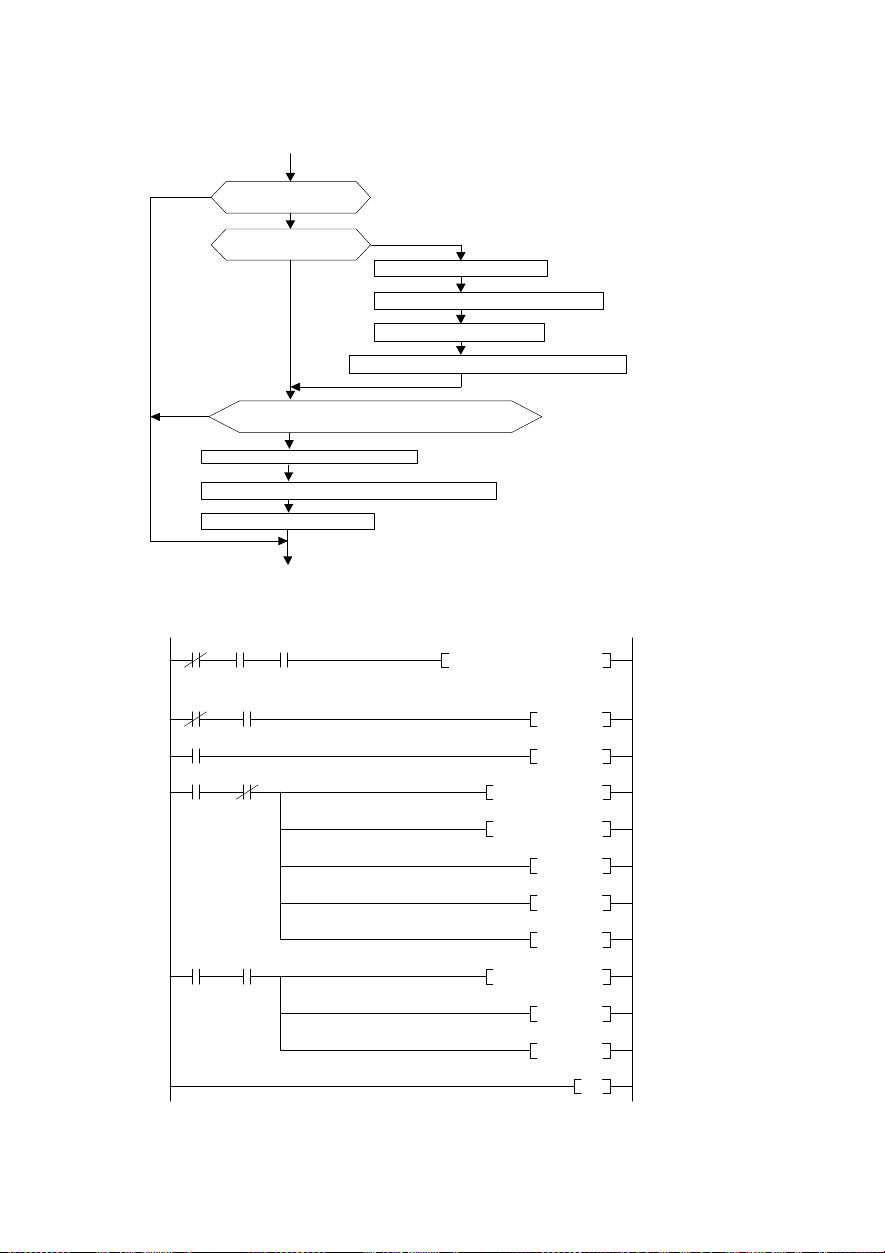
Is th e writin g execu ted?
Turn ON th e com mand code exec
ut ion re quest (RY0F ).
Rea d the respo nse c ode fro m RW r2.
No
12.9 Proc edure for wr iting function codes
Following program change the setting of F07 acceleration time of station 1 RENIC-Eco to 3.0s.
No
Turn OFF t he co mman d cod e exe cutio n requ est (R Y0F).
Turn OFF the d uring-w riting flag.
Yes
Is the du ring-wr iting
Ha s the c omm and c ode ex ecutio n been com pleted ?
flag ON?
Yes
Yes
No
Turn ON t he du ring- writing flag.
Set the co mman d cod e (008 7H) to RWw 2.
Se t the data (
(RX 0F=O N?)
12C
H
) to RWw3 .
Figure
27
X0
Unit f ailure
M0
M300
M301 X100F
Comman d code
X0F X1
Unit
Self-station
readyィ
X20
Writing
ON
execution
complete d
in link
BMOV S W80 K4M0 K4
PLS M 300
SET M 301
MOV H 87 W102
MOV H 12C W103
SET Y 100F
RST M 301
Check the data li nk status of the
station 1
Write F07 write (H87) to R Ww2 and
acceleration time setting data
(H12C) to RWw3.
The command code execution
request (RY0F) is turned ON.
M302
Comman d code
X100F
execution
complete d
Figure
45
SET M 302
MOV W 2 D2
RST Y 100F
RST M 302
28
END
After the command code execution
complete (RX0F) has been turned
ON, the r es ponse code is read out
from the remote register (RWr2) into
D2.
(0: the writing has normally finished.)
The command code execution
request (RY0F) is turned OFF.
Page 48

No
No
Check the data link status of the
Read reply code(RWr2) to D 2 when
the frequency setting comp letion
12.10 Procedure for settin g the command fr equen cy
Following program example changes the command frequency of station 1 RENIC-Eco to 50.00Hz.
No
Is the writing executed?
Yes
Is the during-writing
flag ON?
Yes
Frequency setting complete RAM?
(RX0D=ON?)
Yes
Turn OFF the frequency setting command RAM
Turn OFF the during-writing flag.
Turn ON the during-writing flag.
Set the frequency command (5000) to RWw1.
Turn ON the frequency setting command RAM
Figure
29
X0
Unit f ailure
M0
M300
M301 X100D
Frequency setting
complete
M302
Frequency setting
complete
X0F X1
Unit
Self-station
ready
X20
Writing
ON
X100D
in link
BMOV SW80 K4M0 K4
PLS M300
SET M301
MOV K5000 W101
SET Y100D
RST M301
SET M302
MOV W2 D2
RST Y100D
RST M302
Figure
30
46
END
station 1
Write set frequency to RWr 1
Turn on the frequency sett ing
command RAM(RY0D)ON
(RX0D) turns on.
Turn off the frequency set ting
command RAM(RY0D)ON
Page 49

Is t he du ring
-
read ing
Turn ON t he du ring
-
read ing fl ag.
) to RWw 2.
Rea d out the data fr om R Wr3.
Tur n OF F the c omm and c ode executi on r equest (RY 0F).
Tur n OF F the d uring
-
read ing fl ag.
No
Check the data link status of the
Write error history No.1 a nd No.2
code(RWr2) to D1 and D2 wh en the
12.11 Procedure for reading alarm di finit ion
The following program reads alarm difinitions of station 1
No
Is t he rea ding
exe cuted?
Yes
flag ON?
Yes
Has the c omm and c ode ex ecut ion be en co mple ted?
Yes
Rea d out the r espon se co de fro m RW r2.
Figure
31
No
Set the c omm and c ode (
Turn On t he com ma nd cod e exe cutio n req uest ( RY0F ).
(RX 0F=O N?)
X0
X0F X1
Unit f ailure
Unit
Self-station
ready
in link
X20
M0
Writing
M300
ON
M301 X100F
Command code
execution
complet ed
FRENIC-Eco
74
H
BMOV SW80 K4M0 K4
PLS M300
SET M301
MOV H74 W102
SET Y100F
RST M301
to D1
station 1
read code(H74) to RWw2.
The command code execution
request (RY0F) is turned ON.
M302
Command code
X100F
execution
complet ed
Figure
47
SET M302
MOV W3 D1
MOV W2 D2
RST Y100F
RST M302
32
END
Read alarm data(RWr3) and reply
instruction code execution
completion(RX0F) turns on.
Turn off the command code
execution request (RY0F) .
Page 50

Turn on the error reset request flag
12.12 Pro cedure for resettin g the inverter
The following is a example for resetting station 1
No
Is the error status flag
reset OK?
Yes
Turn off the error reset request flag
Turn off the error status flag
Figure
X0
X0F X01
Unit failure
M0
status flag
Unit
Self-station
ready
X101A X20
Error
in link
Error
reset ON
FRENIC-Eco
33
BMOV SW80 K 4M0 K4
Figure
34
Y101A
END
Turn on the error reset requ est
flag(RY1A)
Turn off the error reset requ est
flag(RY1A), when the error
status flag(R X1 A) is off.
48
Page 51

Chapter13 Troubleshooting
(1)
Option error
Does n ot the profile of
the master station and
the slave station differ?
(master station is ve r1,
but slave station is ver2
etc.)
The installation of the
inverter and the option is
certain.
Install the option again
referring to this manual.
(3)
The command from the CC-Link is not reflected.
The command from
the CC-Link is not
reflect ed.
Has the setting of the
function code y98
"link operation" been
made?
Is [LE] allocated to the
X f unction?
Is the LED (L. ERR) on
the option card lighting
or fl ickering?
Is the setting of the
function c ode o30
"Extended setting"
corre ct?
Is the setting of the
link number correct? It
must be set in
hexadecimal.
Is the data written to
the buffer memory
area (RX, RY, RW w,
RWr) acc ording to
address allocation?
The option card or
inverter unit is
suspected. Contact
Fuji.
(Er4) (2)
Option error (Er4)
has occurred.
Match the profile of the
NO
master station and the
slave station
(communications protocol).
YES
YES
The option card or inverter
unit is suspected. Conta ct
Fuji.
NO
NO
Set y98 correctly.
YES
NO
NO
YES
YES
YES
YES
Turn ON the
appropriate contact.
Check the CC-Link
YES
wiring and th e setting
of the sequencer
CPU.
Match the content set
NO
by "Extended sett ing"
and the syst em
definition.
NO
Recheck the function
code list contained in
the User's Manual
(MHT271□).
NO
Review w riting to the
I/O memory area.
Network error (Er5)
In case of a network error (CC-Link error),
analyze the c ause of the failure by referring
to the RAS information on the sequencer
CPU. For the procedure for referring to the
RAS information and its contents, see the
Sequencer User’s Manual.
A n etwork error
(Er5) has occurred.
Is the power to the
sequencer turned
OFF, or is the master
CPU detached?
Does the detailed RAS
information on the
CPU module indicate
that t he error exists?
Is the station number
setting of the o31
corre ct?
Is wiring cor rect?
・Is any wire broken ?
・Are wires prope rly
connected to the
terminal board?
・Is the
communication line
parallel to the power
line?
・Is the terminal
resiste r connecte d?
・Are t he special
cables used?
・Are the maximum
length of the cable,
the length of the cable
between the stati ons,
and the number of the
connected uni ts as
specif ied.
The option card or
inverter unit i s
suspected. Contact
Fuji.
NO
NO
YES
YES
Turn ON the power to
YES
the seque ncer, reset
the CPU, and clear the
failure of the inverter.
Operation can be
resumed.
YES
Correct the failure of
the station concerned,
and clear the failure
of the inverter.
Match the station
NO
number setting of the
o31 with the station
number set in the
system configuration
definition.
NO
Recheck t he wiring.
49
Page 52

(4) Noise measures
The operation status indicate LED (L. ERR) on the option card is lighting or flickering frequently, there is a
possibility that the communication abnormality by the influence of the noise has been generated. For this case,
following measures are effective. Refer to "Appendix A" of "FRENIC-Eco user's manual (MEH456)" for details.
1) Separate the earth pole of the inverter and the earth pole of other equipment.
2) Separate the power supply system of other equipment and the inverter with the insulation transformer.
3) Separate the main circuit wiring of the inverter with the wiring for the control signal line and other equipment.
4) Use the equipment for the noise measures shown in Figure 35.
Power supply
MCCB
or
ELCB
MC
L1/R L2/S L3/T
R S T
U V W
Inverter
U V W
M
Motor
Name Function
EMC
compliance
filter
Ferrite ring for
reducing radio
noise
Filter capacitor
for reducing
radio noise
This is a special filter which
complies with the European EMC
(Emission) Directive.
Reduces radio frequency noise.
If the wiring between motor and
inverter is shorter than 20m, use
the firrite ring in the power
supply side. If longer than 20m,
use it in the output side.
It uses it to decrease the noise.
The effect of the noise decrease
is achieved for the frequency
band of 1MHz or less that is the
AM Radio Frequency belt.
Never connect it with the output
side of the inverter.
Figure 35
Type
EFL series,
FS5536 series
ACL-40B,ACL-74B,
F200160
NFM25M315KPD1(for
200V),
NFM60FM315KPD(for
400V)
Fuji Electric Technica
Co., Ltd. is supported.
50
Page 53

Chapter14 Speci fications
・
The system does not operate if the setting of the station number (o31) is not correct. Confirm the
following settings, and set the switches to the proper settings.
・Set the option functions with the power to the inverter turned OFF.
Table 16
Hardware specifications
Item
Name CC-Link interface option
Station type Remote device station
Number of
42 units max, compatible with other options
connectable units
・・・・・・・・・・・・・・・・・・・・・・・・・・・・・・・・・・・・・・・・・・・・・・・・・・・・・
Unused
Number of stations
occupied
One station is exclusively occupied
One station is exclusively occupied
One station is exclusively occupied
One station is exclusively occupied
Connection term inal
board
Connection cable
5-terminal board
Use CC-Link dedicated cables (FANC-SBH)
(M3×5
screws
For further information, see the CC-Link catalogue or Mitsubishi FA device
technical information service MELFANS web site
Specifications
(CC-Link Ver1.1)
/double(CC-Link Ver2)
/ quadrople(CC-Link Ver2)
/ octuple (CC-Link Ver2)
)
・・・・・・・・・・・・・
・・・・・・・・
・・・・・
・・・・・・
o30=0
o30=1
o30=2
o30=3
o30=4
o31
o32
Operation status
indication LED
(http://www.nagoya.melco.co.jp/).
Sets station number (address). An arbitrary station number 1 to 64 can be
assigned.
Sets communication speed (Baud rate), 10M / 5M / 2.5M / 625k / 156kbps
L.RUN..............Turned on when refresh data is normally received. Turned off
when the data stops for a certain period of time.
L.ERR..............Turned on when communication error of the self-station occurs.
Flickers if the rotary switch is operated during the power on.
RUN
................. It lights normally, and it blinks CC-Link Ver set by mistake.
SD ...................Turned on during transmission.
RD...................Turned on during reception.
51
Page 54

* Number of connectable units …… Because the number of occupied stations differ according to the number of other
units (remote I/O station, remote device station) and mixed other profiles, the
number of connectable units is required to meet both of the following formulas:
CC-LinkVer 1.10
Formula 1: (1 a) + (2 b) + (3 c) + (4 d) 64
a: Number of stations occupying one station, b: Number of stations occupying two station,
c: Number of stations occupying three station, d: Number of stations occupying four station
Formula 2: (16 A) + (54 B) + (88 C) 2304
A: number of the units in the remote I/O stations 64 units max.
B: number of the units in the remote device stations
C: number of the units in the local stations, waiting master stations,
and intelligent device stations
CC-Link Ver 2.00
Formula 1: { ( a + a2 + a4 + a8 ) + ( b + b2 + b4 + b8 )×2 + ( c + c2 + c4 + c8 )×3 + ( d + d2 + d4 + d8 )×4 }
≦ 64
Formula 2: { ( a×32 + a2×32 + a4×64 + a8×128 ) + ( b×64 + b2×96 + b4×192 + b8×384 ) + ( c×96 +
Formula 3: { ( a×4 + a2×8 + a4×16 + a8×32 ) + ( b×8 + b2×16 + b4×32 + b8×64 ) + ( c×12 + c2×24 +
c2×160 + C4×320 + C8×640 ) + ( d×128 + d2×224 + d4×448 + d8×896 ) } ≦ 8192
C4×48+ C8×96 ) + ( d×16 + d2×32 + d4×64 + d8×128 ) } ≦ 2048
a1: Number of single setting devices occupying one station.
b1: Number of single setting devices occupying two stations.
c1: Number of single setting devices occupying three stations.
d1: Number of single setting devices occupying four stations.
a2: Number of double setting devices occupying one station.
b2: Number of double setting devices occupying two stations.
c2: Number of double setting devices occupying three stations.
d2: Number of double setting devices occupying four stations.
a3: Number of quadruple setting devices occupying one station.
b3: Number of quadruple setting devices occupying two stations.
c3: Number of quadruple setting devices occupying three stations.
d3: Number of quadruple setting devices occupying four stations.
a4: Number of octuple setting devices occupying one station.
b4: Number of octuple setting devices occupying two stations.
c4: Number of octuple setting devices occupying three stations.
d4: Number of octuple setting devices occupying four stations.
・・・・・・・・・・・・・・・・・・・・・・・・・・・・・・・・・・・・・・
・・・・・・・・・・・・・・・・・・・・・・・
42 units max.
26 units max.
Formula 4: (16×A) + (54×B) + (88×C) ≦ 2304
A: number of the units in the remote I/O stations
B: number of the units in the remote device stations
C: number of the units in the local stations, waiting master stations,
and intelligent device stations 26 units max.
・・・・・・・・・・・・・・・・・・・・・・・・・・・・
・・・・・・・・・・・・・・・・・・・・・・・・・
64 units max.
42 units max.
52
Page 55

Do not change the setting of t he station number while the inverter is energized. If the station
number is changed while energized, data communication can not be made with the changed
used or out of the rang e, normal communication can
Set the station number consecutively in order of connections. (If the station number is discontinued,
Do not change the setting of the station number while the inverter is energized. If the station
number is changed while energized, data communication can not be made with the changed
Setting
of station number
(o31)
After turning on the power to the inverter, set the station number of the inverter from 1 to 64.
Table 17
station number specifications
No. station number
0 Setting error (The LED of the L. ERR comes ON.)
1~64 1~64
65~255 Setting error (The LED of the L. ERR comes ON.)
Not e 1)
Transm ission Baud rate
station number.
Not e 2) If the station number is set to a number already
not be made. (The LED of the L. ERR comes ON.)
Not e 3)
(o32)
Set the transmission Baud rate from 0 to 4, after turning on the power to the inverter.
Table 18
Baud rate specifications
No.
0 156kbps
1 625kbps
2 2.5Mbps
3 5Mbps
4 10Mbps
5~255
Not e 1)
(Initial value)
Setting error (the LED of L. ERR comes on.
Baud rate
)
station number.
53
Page 56

Operation status indication LED
The link status of the CC-Link can be confirmed with five LED’s.
Table 19
L.RUN
●:ON, ○:OFF, ★:Flicker (may look like turned on depending on the transmission Baud rate.)
Table 20
Operation
Function code Function codes assigned to the link numbers of the function code list can
Option function code o27, o28, o30, o31, o32
Protective function
Specifications of the operating status indication LED's
L.ERR RUN SD RD
● ○ ● ★ ● Normally communicating
● ★ ● ★ ●
● ★ ● ○ ●
● ○ ● ○ ● Data to the self-station do not come.
○ ★ ● ★ ●
○ ★ ● ○ ● Data to the self-station is CRC error.
○ ○ ● ○ ●
○ ● ● ○ ●○
●
○ ○ ● ★ ● No link startup
○ ○ ● ○ ○
○ ○ ★ ○ ○
Note 1)If the LED’s comes on in other patterns than the above, it can be considered as hardware failure.
★
(0.8s period)
Please contact our company.
Software specifications
Item Specifications
Operation command Forward/Reverse rotation comm ands, alarm reset command, X1~X5
Speed command 16-bit binary data
Operation status
output
Statu s
Normally communicating, but CRC error occurs from
time to time due to noise.
The received data is CRC error, and no response can
be made.
Making the polling response, but received refresh data
is CRC error.
There is no data to the self-station, or data to the
self-station cannot be received due to noise.
Incorrect setting of Baud rate or station number、error
of writing outside range
● ★ ● Baud rate or station number has changed halfway.
Data cannot be received due to broken wire, etc., the
power is off, hardware is being reset, Er3 has
occurred, or the power supply is in failure.
Master station is connected to CC-Link Ver.1 and self
station is connected to CC-Link Ver.2.
CC-Link extended setting is 0,5~255.
commands
Bit data, such as running, braking, torque limitation, and alarm relay output
Word data, such as motor speed and torque current commands
be referred to and changed.
(Refer to Chapter 11.)
Er5: CC-Link error
Option failure (the method of stopping the option can be selected with the
function code o27 or o28.)
・・・・・・・・・・・・・・
Perform ance
The factory-shipped value is 0.
54
Page 57

CC-Link Interface Card "OPC-F1-CCL"
Instr ucti on Manual
Fuji Electric FA Components & Systems Co., Ltd.
The purpose of this manual is to provide accurate information in the handling, setting up and operating of CC-Link Interface
Card "OPC-F1-CCL" for the FREN IC-Eco series of inverters. Please feel free to send your comments regarding any errors or
omissions you may have found, or any suggestions you may have for generally improving the manual.
In no event will Fuji Electric FA Components & Systems Co., Ltd. be liable for any direct or indirect damages resulting from
the application of the information in this manual.
First Edition, June 2006
Page 58

Fuji Electric FA Components & Systems Co., Ltd.
Mitsui Sumitomo Bank Ningyo-cho Bldg., 5-7, Nihonbashi, Odemma-cho, Chuo-ku, Tokyo, 103-0011, Japan
Phone: +81 3 5847 8011 Fax: +81 3 5847 8172
URL
http ://www.f uj iel ectr ic .co.jp /fcs /
2006-06 (K06/G06) CM
 Loading...