

Page 1

Instruction Manual
PG Interface Card "OPC-E1-PG"
Thank you for purchasing our PG interface card.
• Read through this instruction manual and be familiar with the option card
before proceeding with installation, connections (wiring), operation, or
maintenance and inspection.
• Deliver this manual to the end user of this product. Keep this manual in a safe
place until this product is discarded.
• Specifications of this option card are subject to change without prior notice for
improvement.
Fuji Electric Systems Co., Ltd. INR-SI47-1118a-EU REV 052010
Page 2

Copyright © 2006 Fuji Electric FA Components & Systems Co., Ltd.
All rights reserved.
No part of this publication may be reproduced or copied without prior written permission from Fuji Electric Systems Co., Ltd.
All products and company names mentioned in this manual are trademarks or registered trademarks of their respective holders.
The information contained herein is subject to change without prior notice for improvement.
Page 3
Table of Contents
Preface
Thank you for purchasing our PG interface card "OPC-E1-PG."
Mounting this optional card into your FRENIC-Multi inverter enables speed control with PG (e.g. V/f control with PG and dynamic torque vector
control with PG), pulse train input and positioning control.
Read through this instruction manual in conjunction with the FRENIC-Multi Instruction Manual (INR-SI47-1204-E) and be familiar with proper
handling and operation of this product. Improper handling might result in incorrect operation, a sh ort life, or even a failure of this product.
This instruction manual does not contain inverter handling instructions. Refer to the FRENIC-Multi Instruction Manual (INR-SI 47-1204-E), and kee p
this manual in a safe place.
Safety precautions
Read this manual thoroughly before proceeding with installation, connections (wiring), operation, or maintenance and inspection. Ensure you have
sound knowledge of the device and familiarize yourself with all safety information and precautions before proceeding to o perate th e inverter.
Safety precautions are classified into the following two categories in this manual.
Failure to heed the information indicated by this symbol may lead to dangerous conditions, possibly r esulting in
death or serious bodily injuries.
Failure to heed the information indicated by this symbol may lead to dangerous conditions, possibly r esulting in
minor or light bodily injuries and/or substantial property damage.
Failure to heed the information contained under the CAUTION title can also result in serious consequences. These safety precautions are of utmost
importance and must be observed at all times.
Installation and wiring
• Turn the inverter's power OFF and wait for at least five minutes before starting installation and wiring.
• Qualified electricians should carry out wiring.
Otherwise, electric shock could occur.
• Do not use the product that is damaged or lacking parts.
Doing so could cause failure or injuries.
• Prevent lint, paper fibers, sawdust, dust, metallic chips, or other foreign materials from getting into the inverter.
Otherwise, a fire or an accident might result.
• Incorrect handling in installation/removal jobs could cause a failure.
A failure might result.
• Noise may be emitted from the inverter, motor and wires. Implement appropriate measure to prevent the nearby sensors an d devices from
malfunctioning due to such noise.
Otherwise, an accident could occur.
Operation
• Be sure to install the terminal cover before turning the power ON.
Do not remove the cover while the power is on.
Doing so could cause electric shock.
• Confirm and adjust the setting of the function codes before running the inverter.
Otherwise, an accident could occur.
i
Page 4
Maintenance and inspection, and parts replacement
• Turn the power OFF and wait for at least five minutes before starting inspection or parts replacement.
Otherwise, electric shock could occur
• Maintenance, inspection, and parts replacement should be made only by qualified persons.
• Take off the watch, rings and other metallic objects before starting work.
• Use insulated tools.
Otherwise, electric shock or injuries could occur.
Disposal
• Treat the PG interface card as an industrial waste when disposing of it.
Otherwise injuries could occur.
Others
• Never attempt to modify the PG interface card or inverter.
Doing so could cause electric shock or injuries.
Icons
The following icons are used throughout this manual.
This icon indicates information which, if not heeded, can result in the inverter not operating to full efficiency, as well as information
concerning incorrect operations and settings which can result in accidents.
This icon indicates information that can prove handy when performing certain settings or operations.
This icon indicates a reference to more detailed information.
ii
Page 5

Table of Contents
Preface................................................i
Safety precautions ........................... i
Chapter 1
BEFORE USING THE INVERTER ...1-1
1.1 Acceptance Inspection.............1-1
1.2 Mounting the PG Interface Card1-2
1.3 PG Specifications and PG Mounting
Instructions ............................ 1-3
1.3.1 PG specifications.............1-3
1.3.2 Mounting the PG to the
motor ...............................1-3
1.3.3 Wiring between the PG
Interface card and PG...... 1-4
1.3.4 Setting up the power supply
for the PG or pulse train
generator......................... 1-5
1.3.5 Connecting to option
terminals..........................1-5
1.3.6 Option terminals...............1-6
Chapter 2
CONNECTION DIAGRAMS .............2-1
2.1 For Frequency Control with Pulse
Rate Input................................2-1
2.2 For Speed and Positioning
Controls .................................2-2
Chapter 3..............................................
PREPARATION FOR OPERATING .. 3-1
Chapter 4..........PG INTERFACE CARD
FUNCTIONS.......................4-1
4.1 Speed Control..........................4-1
4.2 Frequency Control with Pulse
Rate Input................................4-1
4.3 Positioning Control...................4-1
Chapter 5..............................................
FREQUENCY CONTROL WITH
PULSE RATE INPUT.......... 5-1
5.1 Specifications...........................5-1
5.2 T erminal Functions...................5-1
5.3 Function Code List................... 5-1
5.4 Function Code Details..............5-2
5.5 Description of the Control........ 5-3
5.5.1 Input pulse polarity .......... 5-3
5.5.2 Block diagram..................5-3
Chapter 6
SPEED CONTROL ..........................6-1
6.1 Specifications ..........................6-1
6.2 T erminal Functions .................. 6-1
6.3 Function Code List................... 6-2
6.4 Function Code Details ............. 6-2
Chapter 7
POSITIONING CONTROL ............... 7-1
7.1 Specifications ..........................7-1
7.2 T erminal Functions .................. 7-1
7.3 Function Code List................... 7-2
7.4 Description of the Control........ 7-3
7.4.1 Symbols........................... 7-4
7.4.2 Input/output term functions7-5
7.5 Function Code Details ............. 7-6
7.6 Monitoring................................ 7-6
7.6.1 Monitoring items ..............7-6
7.6.2 Displaying system on the LED
monitor ............................7-7
7.6.3 Positioning control status. 7-7
7.7 Serial Pulse Receiving Function7-8
7.8 Assignment of PG Terminals
When Shared ................................7-9
Chapter 8
PROTECTIVE FUNCTIONS ............ 8-1
8.1 Overspeed Alarm (os).............. 8-1
8.2 Excessive Speed Deviation
Alarm (ere).................................... 8-1
8.2.1 Function codes ................8-2
8.2.2 Excessive speed deviation
detection.......................... 8-2
8.3 Positioning Control Alarm (ero )8-3
8.3.1 Function codes ................8-3
i
Page 6
Chapter 1 BEFORE USING THE INVERTER
1.1 Acceptance Inspection
Unpack the package and check the following:
(1) The PG interface card is the model you ordered.
(2) The PG interface card is not damaged during transportation--no defective parts or lacking parts.
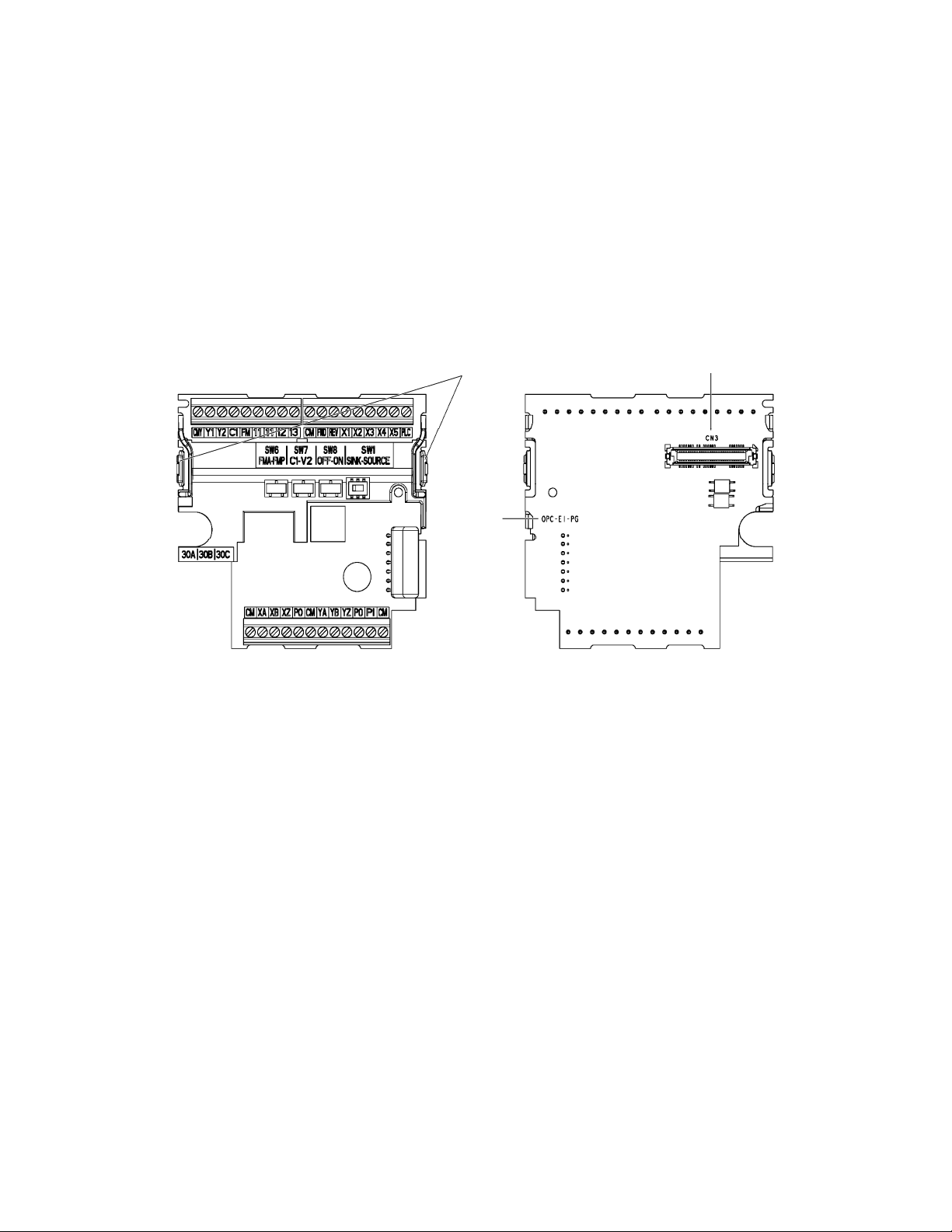
(3) The model name "OPC-E1-PG" is printed on the PG interface card. (See Figure 1.2.)
If you suspect the product is not working properly or if you have any questions about your product, contact your Fuji Electric representative.
Hooks CN3
Model
name
Figure 1.1 Figure 1.2
1-1
Page 7
1.2 Mounting the PG Interface Card
• Turn the power OFF and wait for at least five minutes before starting installation.
Otherwise, electric shock could occur.
• Do not use the product that is damaged or lacking parts.
Doing so could cause a failure and injuries.
• Prevent lint, paper fibers, sawdust, dust, metallic chips, or other foreign materials from getting into the inverter.
Otherwise, a fire or an accident might result.
• Incorrect handling when mounting or removing the product could cause a failure.
A failure might result.
When handling the PG interface card and interface printed circuit board (interface PCB), take any antistatic measure or hold their hooks taking care not
to directly touch their circuit boards; otherwise, the static electricity charged in your body may damage them.
(1) Remove the terminal cover.
For details on how to remove the terminal cover, refer to the FRENIC-Multi Instruction Manual (INR-SI47-1204-E), Chapter 2, Section 2.3
"Wiring."
(2) If the interface PCB is installed on the inverter, push the hooks provided on both ends of the interface PCB and pull it up and out of the inverter with
both hands. (Store the removed interface PCB for future use.)
(3) Connect the CN3 connector (shown in Figure 1.2) on the PG interface card to the connector on the inverter until it clicks into place.
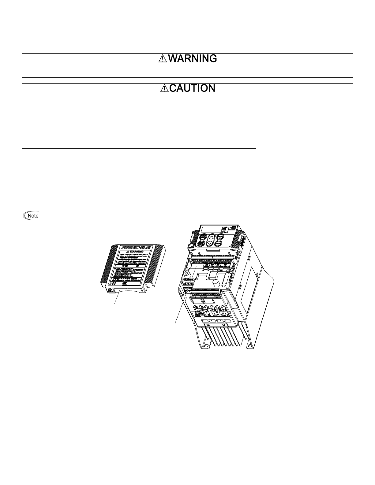
(4) For inverters of 1 HP or below: Before reinstalling the terminal cover, cut off the barrier (see Figure 1.3) of the te rminal cover using nippers or the
like
(5) Reinstall the terminal cover, taking care not to pinch control signal lines.
When reinstalling the terminal cover, refer to the FRENIC-Multi Instruction Manual (INR-SI47-1204-E), Chapter 2, Section 2.3 "Wiring."
For inverters of 5 HP or below: When performing the wiring for the main circuit terminals, you need to remove the PG interface card
beforehand.
Barrier of th
e cable
PG interface card
Figure 1.3
1-2
Page 8
1.3 PG Specifications and PG Mounting Instructions
• Using the PG whose specifications are not satisfied may cause the inverter and equipment to malfunction.
Doing so could cause failure or injuries.
1.3.1 PG specifications
Table 1.2 lists the applicable PG specifications.
Table 1.2 Specifications of Applicable PG and PG Inte rface Card
Item Specifications
Encoder system Incremental system
Applicable PG
PG power
supply
Output signal
Pulse resolution 20 to 3000 P/R
Input power
requirements
5 VDC ±10% / 100 mA
(200 mA, when a single PG is mounted.)
Internal power supply +5 VDC ±10% / 200 mA
External power supply +5 VDC ±10%, 200 mA or more
Open collector (pull-up resistor: 620)
Complementary (totem-pole push-pull) voltage output
Note 1: The wiring length between the PG and inverter should not exceed 20 m.
Note 2: When the PG power is 200 mA or more, use an external power supply.
Note 3: The external power supply should satisfy the voltage specifications of the PG.
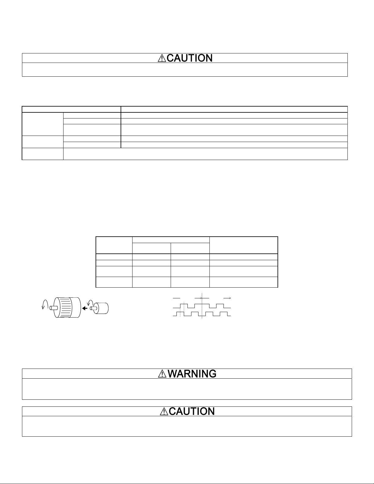
1.3.2 Mounting the PG to the motor
The counterclockwise rotation when viewed from the motor output shaft is regarded as "forward rotation" (see Figure 1.4). During rotation in the forward
direction, the PG output pulse forms the forward signal as shown in Figure 1.5 (B phase advances 90 degrees from A phase). During rotation in the
reverse direction, the PG output pulse forms reverse signal (A phase advances 90 degrees from B phase).
Mount the PG to the motor with a coupling, etc.
Table 1.3 lists the correct configurations of commands, rotational directions, and motor wiring. Any other configuration fails to perform speed control
normally.
Table 1.3 Rotational Direction of Encoder and Motor Shafts
Run
command
Rotational direction
Encoder
shaft
Motor shaft
Motor wiring
FWD Forward Forward U V W phases in order
REV Reverse Reverse U V W phases in order
Figure 1.4
Forward direction
Motor
Forward Direction of Motor and
FWD Forward Reverse U V W phases in reverse
REV Reverse Forward U V W phases in reverse
Forward
signal
A phase
PG
B phase
Figure 1.5 Rotational Direction and Output Signal of PG
90°
order
order
Reverse
signal
PG
Y
ou can monitor the digital input status of the PG interface card with the inverter keypad. For details, refer to the FRENIC-Multi Instruction Manual
(INR-SI47-1204-E), Chapter 3, Section 3.4.5 "Checking I/O signal status."
1.3.3 Wiring between the PG interface card and PG
• Turn the inverter's power OFF and wait for at least five minutes before starting connection.
• Qualified electricians should carry out wiring.
Otherwise, electric shock could occur.
• Noise may be emitted from the inverter, motor and wires. Implement appropriate measure to prevent the nearby sensors and devices from
malfunctioning due to such noise.
Otherwise, an accident could occur.
1-3
Page 9
Wire the PG to the PG interface card, observing the following precautions and referring to the connection diagrams given in Figures 2.1 to 2.3.
(1) Turn the inverter's power OFF.
(2) Use a shielded wire for wiring between the PG and the PG interface card.
(3) To prevent malfunction due to noise, keep the wiring a way from the main circuit wiring of the inverter and the power wiring of other d evices as far as
possible (at least 10 cm(3.94 in)). Do not route them in the same duct.
(4) Complete the wiring for the PG before turning the inverter's power ON.
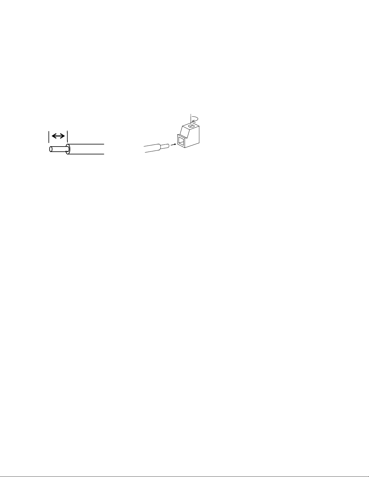
(5) The wire size applicable to the option connection terminal on the inverter is AWG 18-24(0.82 to 0.2 mm
2
).
When using a wire with its end being stripped, strip its end by 5 to 7 mm(0.2 to 0.28 in). When using a ferrule, use a vinyl-insulated ferrule.
Loosen the fixing screw, insert the wire end into the opening of the terminal block, and tighten the screw.
Approx.
6.0 mm(0.24 in)
Figure 1.6 Stripping the Wire End Before Connection to Terminal Board
Recommended wire: AWG 18-24(0.82 to 0.2 mm2) for rated temperature 105°C(221°F) (UL)
1-4
Page 10
1.3.4 Setting up the power supply for the PG or pulse train generator
The external power supply should match the PG power voltage or pulse train generator voltage.
Otherwise, a failure might result.
When using an internal power supply
Connect the power supply wire to the terminal [PO] on the PG interface card.
When using an external power supply
Connect the power supply wire to the terminal [PI] on the PG interface card.
1.3.5 Connecting to option terminals
Table 1.4 lists terminal symbols, names and functions of the option terminals on the PG interface card.
Table 1.4 Option Terminals and Their Specifications
Classif
i-catio
n
Termin
al
symbol
PI
Name Functions
External power
supply input
PO Power supply for PG
Power input terminal from the external device
External power supply capacity:
5 VDC ±10%, 200 mA or more
Power output terminal
5 VDC ±10%, Maximum output 200 mA
CM PG common Common terminal for power supply and PG input
A phase pulse input
XA
X
B phase pulse input
XB
X
PG/ Pulse input
Z phase pulse input
XZ
X
A phase pulse input
YA
Y
B phase pulse input
YB
Y
YZ
Z phase pulse
input Y
Pulse input terminal for commands
To supply speed commands from the pulse train generator or PG, connect an open-collector output signal
or complementary output signal to these terminals.
Since [XZ] is not used for train input control, connection to [XZ] is not required if there is no
corresponding output at the PG. In positioning control, however, connection to [XZ] enables positioning
correction.
Pulse input terminal for feedback
These terminals are for the detection of the inverter-driven motor speed. Connect an open-collector
output signal or complementary output signal to these terminals
Since [YZ] is not used for speed control, connection to [YZ] is not required if there is no corresponding
output at the PG. In positioning control, however, connection to [YZ] enables positioning correction.
Note: Incorrect wiring of A/B phase could fail to run the motor normally or cause an inverter trip.
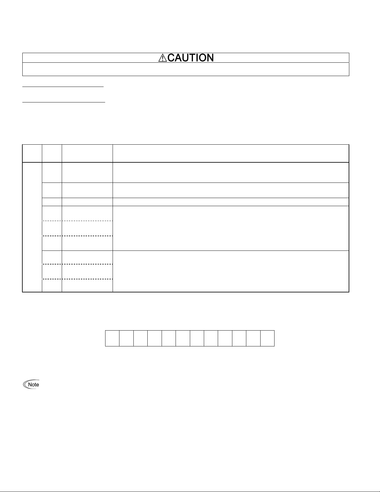
1.3.6 Option terminals
CM XA XB XZ PO CM YA YB YZ PO PI CM
Screw size: M2
Tightening torque: 0.22 to 0.25 N·m(0.16 to 0.18 lbf·ft)
Terminal [PLC] on the PG interface card cannot su pply power to external equipment. Use the terminal onl y for receiving power from external
equipment.
Figure 1.8 Option Terminals
1-5
Page 11
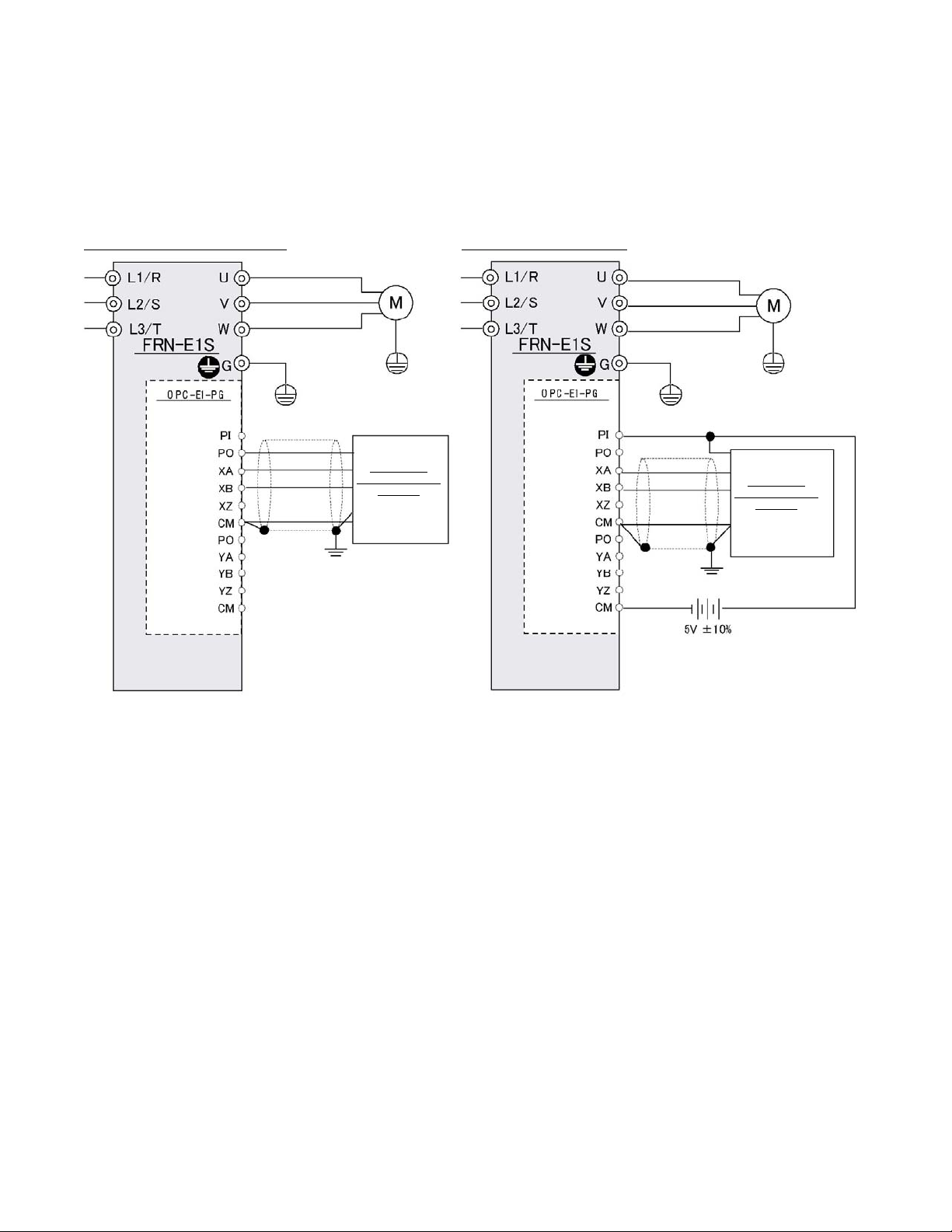
Chapter 2 CONNECTION DIAGRAMS
2.1 For Frequency Control with Pulse Rate Input
Figure 2.1 sh o ws connec tion di agram e xampl es for fr eq uenc y c ont rol wi th puls e r ate input.
Note 1)
Figure 2.1 Connection Diagrams for Frequency Control with Pulse Rate Input
When using inverte r inter nal pow er sup ply
Pulse Train
Generator or PG
(Note 1)
When using exte rnal p o we r s uppl y
For details about applicable PG specifications, refer to Table 1.2 in Chapter 1, Section 1.3.1 "PG specifications."
Pulse Train
Generator or PG
(Note 1)
2.1
Page 12

Chapter 3 PREPARATION FOR OPERATING
After completion of mounting/wiring but before turning the inverter's power ON, check the followings.
(1) The wiring is correct.
(2) There is no cable waste or screws left.
(3) The screws and terminals are firmly tightened.
(4) The straggling wires at ferrules are not short-circuited to other terminals.
Furthermore, after powering the inverter ON but before starting inverter operation, check the followings.
• Check the wiring surely before running the inverter. Incorrect wiring causes the inverter or other devices to malfunction.
Failure to do so could cause failure or injuries.
• Be sure to mount the terminal cover before turning the power ON.
Do not remove any cover while the power is ON.
Doing so could cause electric shock.
• Confirm and adjust the setting of the function codes before running the inverter.
Otherwise, an accident could occur.
3-1
Page 13

Chapter 4 PG INTERFACE CARD FUNCTIONS
The combination of the PG interface card and the PG (open collector or complementary output) makes feedback signals available, enabling the following
controls.
4.1 Speed Control
This refers to speed control with PG. (For details, refer to Chapter 6.)
4.2 Frequency Control with Pulse Rate Input
This control specifies a frequency command with pulse trains. (For details, refer to Chapter 5.)
It can be used together with speed control with PG at the same time.
4.3 Positioning Control
This refers to simplified positioning control that detects the pulse count with feedback signals sent from the PG. (For details, refer to Chapter 7.)
This control can be used together with speed control with PG and frequency control with pulse rate input at the same time.
4-1
Page 14

Chapter 5 FREQUENCY CONTROL WITH PULSE RATE INPUT
r
The pulse rate input feature supplies a frequency command to the inverter in pulse trains. Two pulse input modes are available--B phase pulse (with signs)
and forward/reverse rotation pulse trains.
The frequency control with pulse rate input can be enabled concurrently with the speed and positioning controls with PG.
5.1 Specifications
Table 5.1 lists the specifications of frequency control with pulse rate input.
Table 5.1 Specifications for Pulse Train Inputs
Item Specifications
Reference frequency range 0 to 400 Hz
Frequency accuracy
Output circuits
Input pulse level
Maximum cable length and maximum input
pulse rate
0.2% of maximum frequency
Open collector
Complementary
5 VDC 10%
20 m, 30 kp/s
5.2 Terminal Functions
Table 5.2 lists terminal specifications.
Table 5.2 Terminal Specifications
Terminal
symbol
Name Descriptions
PI Power input terminal Receives power for the PG from an external source.
PO Power output terminal Outputs power to the PG.
CM Common terminal Common terminal for the PG power.
XA
XB
Command input terminal
for A phase pulse train
Command input terminal
for B phase pulse train
Receives an A phase feedback pulse train.
Receives a B phase feedback pulse train.
XZ -- Reserved.
The pulse count of [XA] and [XB] terminal inputs can be displayed on the keypad by using Menu #4 "I/O Checking," Check item 4_15. Fo
details, refer to the inverter’s instruction manual. (See the description of function code E52.)
5.3 Function Code List
Table 5.3 lists function codes to be used for pulse rate input. Mounting the PG interface card can display o codes.
Table 5.3 Related Function Codes
Code Name
F01
Frequency Command 1
(C30
(Frequency Command 2)
)
Com-
o01
mand/Feedback
(Input mode)
Input
Command:
o06
(Pulse train
(Filter time constant)
input)
o07
o08
(Pulse count factor 1)
(Pulse count factor 2)
Data
setting
range
0 to 3, 5.
7. 11, 12
0, 1, 2,
10, 11, 12
20, 21, 22
0.000 to
5.000
1 to
9999
1 to
9999
Unit
Default
setting
-
0
(2)
Change when running
N
- 0 N
s 0.005 Y
- 1 N
- 1 N
5-1
Page 15

5.4 Function Code Details
F01 Frequency Command 1 (C30: Frequency Command 2)
To drive the inverter with the pulse input frequency command, set the F01 (C30) data to "12" for frequency command 1 (frequency command 2).
o01 Command/Feedback Input (Input mode)
This function code switches the pulse input mode with the data in the ones place as listed in Table 5.4.
Table 5.4 Data for o01
Pulse input mode Data for
B phase pulse
input
Pulse input with
polarity
A/B phase pulse
input
o01
0
1
2
Not available (This setting produces 0
p/s.)
o06 Command (Pulse train input) (Filter time constant)
This function code specifies a time constant determining a linear delay of the low pass filter for the reference speed given by pulse train. Adjusting this
time constant can stabilize the speed command in low pulse rate.
o07
o08
Command (Pulse train input) (Pulse count factor 1)
Command (Pulse train input) (Pulse count factor 2)
For the pulse input command, these function codes define the relationship between the input pulse rate and reference frequency.
Reference frequency
*
f
(Hz)
o08
Remarks
Input pulse rate
Np (kp/s)
0
o07
Figure 5.1 Relationship between the Input Pulse Rate and Reference Frequency
As shown in Figure 5.1, set the input pulse rate (kp/s) to the o07 data and set the reference frequency (Hz) at the pulse rate (specified by o07) to the o08
data. The relationship between the input pulse rate at A or B phase input and the reference frequency f* (or reference speed) can be calculated by the
following expression.
Pulse count factor 2
f* (Hz) = Np (kp/s)
(o08)
Pulse count factor 1
(o07)
f* (Hz)
Np
(kp/s)
: Reference frequency (In speed control, the frequency corresponding
to the speed)
: Input pulse rate at A or B phase input
5-2
Page 16

5.5 Description of the Control
5.5.1 Input pulse command polarity
In the B phase pulse input system shown in Figure 5.2, the A phase voltage determines the polarity of commands. In the run forward/reverse pulse input
system shown in Figure 5.3, the presence of A or B phase input determines the polarity of commands.
The combination of the command pulse input and FWD/REV command determines the actual motor rotational direction. Table 5.5 lists the relationship
between the polarity of the pulse input, FWD/REV command and motor rotational direction.
Polarity
+ -
A phase input
B phase input
Figure 5.2 Polarity of the B Phase Pulse Input
Polarity
+ -
A phase input
B phase input
Figure 5.3 Polarity of the Run Forward/Reverse Pulse Input
Table 5.5 Relationship between Polarity of the Pulse Input, FWD/REV Command
and Motor Rotational Direction
Command polarity deter-
mined by pulse input
+ FWD Forward
+ REV Reverse
- FWD Reverse
- REV Forward
5.5.2 Block diagra m
Figure 5.4 shows a block diagram of the pulse train input command system.
Run command
Motor rotational direc-
tion
[XA]
[XB]
o01
Input
mode
Frequency
measuring
Pulse count
factoring
o08
o07
o06
UP/DOWN keys on keypad
[12]
UP/DOWN keys on keypad
[12]
[C1]
Frequency
command 1
12
0
1
Frequency
command 2
0
1
2
Select frequency
command 2/1
Hz2/Hz1
F01
C30
Figure 5.4 Block Diagram of the Pulse Train Input System
5-3
Rotation
direction
processing
FWD
REV
Drive frequency
command
Page 17

Chapter 6 SPEED CONTROL
r
Using a PG feedback signal enables V/f control with PG and dynamic vector control with PG.
It speed-controls the detection speed of the motor via the PG and compensates the frequency with PI control so that the motor speed follows the speed
command.
The speed control with PG can be enabled concurrently with the frequency control with pulse rate input and positioning control.
6.1 Specifications
Table 6.1 lists the specifications of speed control with PG.
Table 6.1 Specifications of Speed Control with PG
Item Specifications Remarks
Speed control
Control
Electrical
specifica-
tions
range
Speed control
accuracy
Input pulse rate 75 p/s to 30 kp/s
6.2 Terminal Functions
Table 6.2 lists terminal functions.
Loca-
tion
Termi-
nal
symbol
PI Power input terminal Receives power for the PG from an external source.
PG
interface
card
PO Power output terminal Outputs power to the PG.
CM Common terminal Common terminal for the PG power.
YA Feedback input terminal for A phase pulse train Receives an A phase feedback pulse train.
YB Feedback input terminal for B phase pulse train Receives a B phase feedback pulse train.
YZ -- Reserved.
Terminal
Inverter
"Switch speed control" terminal Temporarily cancels speed control with PG.
[X]
(Note)
The pulse count of [YA] and [YB] terminal inputs can be displayed on the keypad by using Menu #4 "I/O Checking," Check item 4_17. Fo
details, refer to the inverter’s instruction manual. (See the description of function code E52.)
(Note) "Switch speed control" terminal
Setting "27" to any of function codes E01 to E05, E98 and E99 assigns the "Switch speed control" command PG/Hz to the corresponding one of digital input
terminals [X1] to [X5], [FWD] and [REV]. This setting enables the assigned terminal to be used for cancelling the speed control with PG. While the inverter
is running, turning this terminal on or off will be ignored. After the inverter stops, it will be validated. If n o PG/Hz is assigned, speed control with PG is always
enabled.
180 to 3600 r/min
When running at constant speed
0.2% of maximum
speed
(The maximum speed refers to the speed corresponding to the maximum frequency.)
Maximum wiring length: 20 m when using A/B phase pulse input
Table 6.2 Terminal Functions
Name Functions
Table 6.3 Function of PG/Hz Terminal Command
Terminal command PG/Hz Function
ON Enable speed control with PG
OFF Disable speed control with PG
6-1
Page 18

6.3 Function Code List
Table 6.4 lists function codes to be used for speed control with PG.
Mounting the PG interface card can display o codes.
Table 6.4 Related Function Codes
Cod
e
F42
Control Mode Selection 1
(A14
(Control Mode Selection 2)
)
Command/
o01
Feedback Input
o02 Speed Control (P Gain) 0.01 to 200.00 Times 10.00 Y
o03 (Integral time) 0.000 to 5.000 s 0.100 Y
o04 (Filter time constant) 0.000 to 5.000 s 0.020 Y
Feedback Input
o09
o10 (Filter time constant) 0.000 to 5.000 s 0.005 Y
o11 (Pulse count factor 1) 1 to 9999 - 1 N
o12
o13 Speed Control (Output limiter) 0.00 to 100.00 % 100.00 Y
6.4 Function Code Details
F42 Control Mode Selection 1 (A14: Control Mode Selection 2)
To select the V/f control with PG interface or dynamic torque vector control with PG interface, set the F42 (A14) data to "3" or "4," respectively.
o01 Command/Feedback Input (Input mode)
This function code switches the feedback pulse input mode with the data in the tens place as listed below.
o02
o03
These function codes specify the PI constants of a speed controller. The expression below shows the transfer function of the controller.
Speed Control (P Gain)
Speed Control (Integral time)
Name Data setting range Unit
0 to 4 - 0 N
(Input mode)
(Encoder pulse resolu-
(Pulse count factor 2) 1 to 9999 - 1 N
0, 1, 2,
10,11,12,
20,21,22
20 to 3600 P/R 1024 N
tion)
Table 6.5 Data for o01
Feedback pulse input mode Data for o01
B phase pulse input 0
Forward/reverse pulse input 1
A/B phase pulse input 2
- 0 N
Default
setting
Change
when
running
1
I
ε)
×+=
is 1% of the maximum frequency.
S
6-2
(1kf
PS
sT
: P gain (o02)
K
p
T
: Integral time (o03)
I
f
: Slip frequency
S
: Speed deviation
s : Laplace operator
Suppose that the P gain is 1.0 when the speed deviation = 100% (Maximum Frequency F03 (A01)) and f
Suppose that the I integral time = 1.000 seconds when the o03 data is 1.000.
Setting an excessive P gain may cause system hunting. A roughly recommended P gain should not exceed 35.00 in the ordinary system.
Modifying F03 (A01) data requires readjustment of o02 and o03 data.
Page 19

o04 Speed Control (Filter time constant)
This function code specifies a time constant determining a linear delay of the low pass filter for the speed command given by pulse train. Use this
function code to suppress an overshoot that occurs, for example, when the speed command varies.
o09 Feedback Input (Encoder pulse resolution)
This function code specifies the resolution of the encoder mounted on the inverter-driven motor.
o10 Feedback Input (Filter time constant)
This function code specifies a time constant determining a linear delay of the low pass filter for the speed feedback given by pulse train. Use this
function when large ripple components superpose the feedback pulse train.
o11
o12
Feedback Input (Pulse count factor 1)
Feedback Input (Pulse count factor 2)
These function codes specify pulse count factors 1 and 2.
Use these function codes when the motor shaft speed differs from the encoder (PG) shaft speed depending upon a transmission reduction ratio.
Refer to Figure 6.1 and the expressions below for calculation of the count factors.
Conveyer
Ge a r tr ain
(Trans m iss ion
ratio: a/b)
Pu lle y
(Trans m iss ion
ratio: c/d)
Radius: d
[YA],[YB]
Power
supply
Motor shaft speed =
o13 Speed Control (Output limiter)
This function code specifies the output limit percentage for the speed controller (PI controller). Specification of 100.00% is equivalent to the maximum
speed (maximum frequency).
T o suppress the frequency control amount (PI controller output) to the extent of the motor's slip frequency in the speed control mode, use this function.
Pulse count factor 2
(o12)
Pulse count factor 1
(o11)
Pulse count factor 2
(o12)
Pulse count factor 1
(o11)
PG
Radius: c
L1/R, L2/S, L3/T
=
Inve rte r
FRN-E1S
Figure 6.1 Speed Control Model Using a PG
Encoder shaft speed
b d
a c
No. of teeth: b
No. of teeth: a
No. of teeth: a
Motor
U, V, W
6-3
Page 20

Chapter 7 POSITIONING CONTROL
Using PG feedback signals enables positioning control. The inverter internally counts the feedback pulses and controls the motor so that the control object
moves from the previously specified start point, decelerates and switches to the creep speed operation to arrive at the specified stop position.
The positioning control can be enabled concurrently with the frequency control with pulse rate input and speed control with PG.
7.1 Specifications
Table 7.1 lists the specifications of positioning control.
Table 7.1 Specifications of Positioning Control
Item Specifications Remarks
Speed
control
Pulse input
Range
Maximum pulse
rate
7.2 Terminal Functions
T able 7.2 list s terminal functions for the positioning control alone (no concurrent use of the speed control with PG or frequency control with pulse rate input).
Table 7.2 Terminal Functions
(no concurrent use of speed control with PG or frequency control with pulse rate input)
Terminal
symbol
PI Power input terminal
PO Power output terminal Outputs power to the PG.
CM Common terminal Common terminal for the PG power.
Command input terminal
XA
for A phase pulse train
Command input terminal
XB
for B phase pulse train
XZ -- Reserved.
Feedback input terminal
YA
for A phase pulse train
Feedback input terminal
YB
for B phase pulse train
Feedback input terminal
YZ
for Z phase pulse train
• The pulse count of [XA], [XB], [YA], [YB] and [YZ] inputs can be displayed on the keypad by using Menu #4, "I/O Checking," Check items 4_15,
4_17, and 4_18. For details, refer to the inverter's instruction manual. (See the description of function code E52.)
• When the positioning control is enabled concurrently with the speed control with PG or frequency control with pulse rate input, the specif ications
of terminals [XA], [XB], [XZ], [YA], [YB], and [YZ] differ from the ones listed above. For details, refer to Section 7.8 "Assignment of PG Terminals
When Shared." (Refer to the description of function code o01.)
Name Functions Remarks
Receives power for the PG from an external source.
Receives an A phase command pulse
train.
Receives a B phase command pulse train.
Receives an A phase feedback pulse train.
Receives a B phase feedback pulse train.
Receives a Z phase feedback pulse train.
180 to 3600
r/min
30 kp/s
Wiring length: Max.
20 m
Specify the input mode with J86.
Specify the input mode with o01.
No connection needed if no preset positions are specified with
J76 and J77.
7-1
Page 21

7.3 Function Code List
Table 7.3 lists function codes to be used for positioning control. Mounting the PG interface card can display o codes.
Table 7.3 Function Codes
Code Name Data setting range Unit Default setting
E01
to
E05,
Terminal [Xn] Function
E98,
E99
E20,
E21,
E27
Terminal [Y1] Function
Terminal [Y2] Function
Terminal [30A/B/C]
Function
Positioning Control
J73
(Start timer)
J74 (Start point, upper digits) -999 to 999 p 0 Y
J75 (Start point, lower digits)
J76
J77
(Preset point, upper
(Preset point, lower dig-
(Creep speed switch
J78
upper digits)
(Creep speed switch
J79
lower digits)
J80 (Creep speed) 0 to 400 Hz 0 Y
J81 (End point, upper digits) -999 to 999 p 0 Y
J82 (End point, lower digits) 0 to 9999 p 0 Y
J83 (Positioning allowance) 0 to 9999 p 0 Y
J84 (End timer)
J85
(Coasting compensa-
J86 (End point command)
J87
J88
(Preset positioning re-
quirement)
(Position detection di-
rection)
Command/Feedback
o01
Input
(Input mode)
1 [P]: Current position (Absolute position)
*
Switching between "0" and [P] requires the simultaneous keying:
*2 Even if wrong wiring of the PG inverts the position detection direction, using J88 can correct the direction without rewiring.
42 (1042): Activate the limit switch at start point, LS
43 (1043): Start/reset, S/R
44 (1044): Switch to the serial pulse receiving mode, SPRM
- - N
45 (1045): Enter the return mode, RTN
80 (1080): Stop position override alarm, OT
81 (1081): Timer output, TO
82 (1082): Positioning completed, PSET
- - N
83 (1083): Current position count overflowed, POF
0.0: Disable
0.1 to 1000.0: Preset time
[P], 0 to 9999 *1
-999 to 999 p 0 Y
digits)
[P], 0 to 9999 *1
its)
0 to 999 p 0 Y
point,
point,
0 to 9999 p 0 Y
0.0: Disable.
0.1 to 1000.0: Preset time
0 to 9999 p 0 Y
tion)
0: B phase pulse input
1: Pulse input with polarity
s 0.0 Y
p 0 Y
p 0 Y
s 0.0 Y
- 0 Y
0: Forward rotation direction
1: Reverse rotation direction
- 0 N
2: Both forward/reverse rotation direction
2
*
0: Forward direction
1: Invert the current direction ( -1).
- 0 N
0, 1, 2,
10,11,12,
- 0 N
20,21,22
+ keys from "0" to [P] and + keys from [P] to "0."
Change when
running
7-2
Page 22

7.4 Description of the Control
The PG interface card allows the inverter to internally count feedback pulses issued from the encoder (PG) and control the motor so that the control object
starts moving from the previously specified start point (S point), decelerates and switches to the creep speed operation to arrive at the specified stop
position (E point).
Turning a run command ON with "Start/reset" command S/R being ON starts the positioning control.
See Figure 7.1 "Positioning Control Model" and Table 7.4.
Frequency Hz
Reference
frequency
Creep speed (J80)
Time
ST (J73)
)
0
1
E
/
7
0
F
(
e
m
i
t
l
c
c
A
L (J78, J79)
D
e
c
l
t
i
m
e
CP (J85)
ER (J83)
(
F
0
8
/
E
1
1
)
Time
ET (J84)
t
0
S point
(J74, J75)
Z point
(J76, J77)
Start/reset S/R OFF
Run command
Timer output TO
Positioning
completed PSET
OFF
OFF
OFF
Note: The current position must be within E +/- ER
point after the tim e ET has elapsed.
Figure 7.1 Positioning Control Model
• The positioning control applies to motor 1 only.
• During jogging (inching) operation or when the PID control is enabled (J01 0), the positioning control is disabled.
• An undervoltage alarm that occurs in positioning control triggers an alarm ero; however, the inverter does not enter the restart mode
(specified by F14).
• Enabling the positioning control disables the auto-reset function specified by H04 and H05.
The operation status in positioning control can be displayed on the keypad by using Menu #3 "Drive Monitoring." For details, refer to Section
7.6 "Monitoring." (See the description of function code E52.)
ON
ON
Decl time
(F08/E11)
ON
E point
(J81, J82)
ON
7-3
Page 23

7.4.1 Symbols
Table 7.4 lists the meanings of symbols used in Figure 7.1.
Table 7.4 Symbol Details
Symbol Name
S point Start point J74, J75
ST Start timer J73 This specifies the waiting time from when a run command comes ON with the S/R terminal command being ON until
Z point Preset
position
L Creep
speed
switch
point
CP Coasting
correction
E point End point J81, J82 This specifies a target stop position.
ER Positioning
allowance
ET End timer J84 This specifies the waiting time from when the control object stops at E point until the inverter can receive the next
Function
code
Descriptions
This specifies the start position data for the positioning control. It can be the current position [P] (absolute position)
or numerical value (relative position). Specification of an absolute position and that of a relative position produce
different results as described below.
[Absolute position]
Specifying [P] regards the current position as a start point. When starting the positioning control, the inverter applies
the current position pulse count as start point data.
(Example) Suppose that the current position pulse count = 10,000, the start point data = [P], and the stop point (E
point) pulse count = 20,000.
Then, when starting the positioning control, the inverter moves the control object from the current position (10,000,
as start point data) to the E point (20,000). Accordingly, the object moving pulse count is 10,000 (20,000 - 10,000).
[Relative position]
Specifying "a" (numerical value) substitutes "a" for the current position data. When starting the positioning control,
the inverter applies "a" pulses as start point data.
(Example) Suppose that the current position pulse count = 10,000, start point data "a" = 4,000, and the stop position (E point) pulse count = 20,000.
Then, when starting the positioning control, the inverter moves the control object from the start point pulse count "a"
(4,000) instead of the current position data (10,000) to the E point (20,000). Accordingly, the object moving pulse
count is 16,000 (20,000 - 4,000).
the inverter starts running the motor. (This covers the delay of brake OFF.)
If the output frequency has not been zero (inverter running), turning the terminal command S/R ON does not start
the timer count. (During deceleration triggered by turning the run command OFF, the start timer does not start as
well.)
J76, J77 When the inverter detect s that the Z signal is turned from Low to High first after the LS terminal command is turned
from OFF to ON, it corrects the current position data for the preset position data (Z point). This is functionally
equivalent to a mechanical position correction or origin point reset.
Specifying [P] to the preset position does not perform the Z point correction.
It is also possible to restrict the application of the Z point correction with the LS to the motor rotational direction
specified by function code J87.
J78,
J79
This specifies an absolute position pulse count required from a deceleration start point (towards the creep speed
specified by J80) to the E point.
J85 This specifies the deceleration start point that follows the end of creep-speed operation. Specify it with the pulse
count from the E point.
Take into account the inertia produced when the control object decelerates to stop.
J83 This specifies the positioning allowance at the E point, that is, "Actual stop position - E point position."
After the end timer counts up:
If "Actual stop point - E point " ER, the inverter issues the "Positioning completed" signal PSET.
If "Actual stop point - E point " ER, the inverter issues the "Stop point alarm" signal OT.
positioning control signal.
After completion of positioning, when this waiting time has elapsed or when 0.5 second has elapsed if ET < 0.5
second, the inverter issues the "Positioning completed" signal PSET or "Stop point alarm" signal OT.
Turning the run command OFF when the ET is counting interrupts the counting, so the inverter does not issue PSET
or OT.
The inverter ensures that PSET and OT signals are kept ON for at least 100 ms.
7-4
Page 24

7.4.2 Input/output terminal functions
Termi-
Terminal
function
Activate
the limit
switch at
start
point
Start/reset S/R
Switch to
the serial
pulse
receiving
mode
Enter the
return
mode
Terminal
function
Stop position override alarm
Timer output
Positioning completed
Current
position
count
overflowed
nal
com-
mand
This is used when the inverter corrects the current position data for the preset position data (Z point) specified by function codes
J76 and J77.
When the inverter detects that the Z signal is turned from Low to High first after the LS terminal command is turned from OFF to
LS
ON, it triggers the Z point correction.
In any other conditions, the LS terminal command produces nothing.
This enables or disables the positioning control.
ON: Enable
OFF: Disable
This enables or disables the serial pulse receiving mode.
When the serial pulse input shares an input terminal with other functional pulse inputs (when the positioning control is concurrently enabled with frequency control with pulse rate input and/or speed control with PG) with function code setting, the
inverter counts input pulses only from the PG for the stop position when the SPRM terminal command is ON.
SPRM
ON: Enable
OFF: Disable
If the serial pulse receiving is exclusively assigned to the digital input terminal for the PG input, however, the inverter counts the
input pulses for the stop position, regardless of the SPRM status.
Turning the SPRM ON zero-clears the pulse count (E point data previously specified by J81 and J82).
Starting the positioning control with the RTN terminal command being ON enables the return mode in which the inverter moves
the control object in the reverse direction while keeping the S and E point data.
RTN
Using the RTN enables the reciprocal positioning control; moving from S to E points and returning from E to S points.
ON: Enable
OFF: Disable
The zero-clear function of the received pulse count (E point specified by J81 and J82), which can be triggered by turning the SPRMfrom OFF to
ON, is always enabled. Take care not to zero-clear the E point mistakenly.
When the positioning control is enabled concurrently with the speed control with PG or frequency control with pulse rate input, the specifications
of terminals [XA], [XB], [XZ], [YA], [YB], and [YZ] dif fer from the ones listed above. For details, refer to Section 7.8 "Assignment of PG Terminals
When Shared." (Refer to the description of function code o01.)
Sym-
bol
ON conditions
O
The ET time has elapsed (or after 0.5 second if ET < 0.5 s) or
"Actual stop position – E-point" > ER data.
T
OFF conditions
Except the above ON conditions.
ON conditions
TO
Until the ET time has elapsed after the start timer (J73) starts.
OFF conditions
Except the above ON conditions. When the ET is cancelled, the output frequency becomes 0 Hz, turning this signal OFF..
ON conditions
The ET time has elapsed (or after 0.5 second if ET < 0.5 s) or
PSET
"Actual stop position – E-point" > ER data.
OFF conditions
Except the above ON conditions.
ON conditions
The current position pulse count goes out of the range from -9,999,999 to +9,999,999, regardless of the ON/OFF state of the
SR terminal command.
OFF conditions
POF
The position count comes within the specified range after going out of the range,
Any run command is turned ON with the S/R being ON, or
A Z point correction is performed.
Table 7.5 Input Terminal Functions
Description
Table 7.6 Output Terminal Functions
Description
7-5
Page 25

7.5 Function Code Details
o01 Command/Feedback Input (Input mode)
This function code switches the feedback pulse input mode with the data in the tens place as listed below.
Table 7.7 Data for o01
Feedback pulse input mode Data for o01
B phase pulse input 0
Forward/reverse pulse input 1
A/B phase pulse input 2
When the positioning control is enabled concurrently with the speed control with PG or frequency control with pulse rate input, the specifications
of terminals [XA], [XB], [XZ], [YA], [YB], and [YZ] dif fer from the ones listed above. For details, refer to Section 7.8 "Assignment of PG Terminals
When Shared." (Refer to the description of function code o01.)
7.6 Monitoring
The positioning control status and the pulse count can be displayed on the keypad by using Menu #3 "Drive Monitoring" as described in this section.
7.6.1 Monitoring items
Table 7.8 Function Code E43 (LED Monitor, Item selection)
Data
for
E43
21
22
LED
moni-
tor
shows:
3_17
3_18
3_19
3_20
Monitor items Unit Descriptions Refer to:
Current position pulse
count
Position deviation
pulse count
Monitor items Unit Descriptions Refer to:
E point pulse count p
Current position pulse
count
Position deviation
pulse count
Positioning control
status
Displays the current position pulse count.
p
Displays the pulse count deviation between the current position
p
and the stop position.
Table 7.9 Menu #3 "Drive Monitoring"
Displays the E point of positioning control in the pulse count.
Turning RTN OFF displays E point (J81 and J82); turning it ON
displays S point (J74 and J75).
Displays the current position pulse count.
p
Displays the pulse count deviation between the current position
p
and S point.
Displays the position control status shown in Section 7.6.3 "Posi-
--
tioning control status."
Section 7.6.2
Section 7.6.2
Section 7.6.3
7.6.2 Displaying system on the LED monitor
The positioning control handles the pulse count ranging from 9,999,999 to +9,999,999. To display it, the 4-digit LED monitor alternately the upper and lower
four digits for one second and three seconds, respectively. The lower four digits is followed by a decimal point.
Table 7.10 Displaying System for Pulse Count
- Running status in Running mode and running info in
Pulse
count
+9,999,999 +999 9999. Maximum display
+19,999 +1 9999.
+10,000 +1 0000.
+9,999 +0 9999.
-9,999 -0 9999.
-10,000 -1 0000.
-19,999 -1 9999.
-9,999,999 -999 9999. Minimum display
Programming mode on the standard keypad
- Running status in Running mode on the multi-function
keypad
Upper 4 digits Lower 4 digits
+10 +0 0010.
0 0 0000.
-10 -0 0010.
Remarks
value
The lower digits
are not
zero-suppressed.
value
7-6
Page 26

7.6.3 Positioning control status
In positioning control, the keypad can display the current control status. Figure 7.2 shows a control status transition model and T able 7.11 lists details of the
status.
ON
CP = 6
L
CP
Time
ET
Once entering into CAN
status, the inverter remains
Time
in this state even if any run
ST
command turns ON.
t
S point
ON
ON
ON
ON
ON
CAN=10L = 5 ET = 7
WAIT
=1
ON
ON
PSET=8
or OT=9
Descriptions
WAIT
=1
RUN = 3
= 2
ON
ST
Frequency Hz
Reference frequency
Creep speed
0
Start/reset S/R
Run command
Timer output
TO
Positioning
completed PSET
Stop position
override alarm OT
Positioning
control status
OFF
OFF
OFF
OFF
STOP
= 0
Time
ST
S point E point
WAIT
ST
= 1
= 2
RUN = 3
Z point
ON
- After ET has elapsed, the current
position is within the range of E +/- ER.
- After ET has elapsed, the current
position is out of the range of E +/- ER.
Z = 4
Figure 7.2 Positioning Control Status Transition Model
Table 7.11 Status Name and Number in Positioning Control
Positioning
control status
Positioning
control
stopped
Waiting for run
command
Status
name
STOP 0 Status where S/R is OFF. Turning S/R ON shifts to "WAIT = 1" where the inverter waits for a run command.
WAIT 1 Status where S/R is ON and a run command is OFF.
Status
number
1
*
*2
If the inverter output frequency is other than 0 Hz (Gate output) when S/R is turned ON, it shifts to "RUN = 3"
since the start timer does not count.
Turning a run command ON in this status shifts to "ST = 2."
If the start timer (J73 data) is 0.0 s, the status shifts from "WAIT = 1" to "RUN = 3."
Start timer
counting
Running RUN 3
ST 2 Status where S/R and run command are ON and the start timer is counting.
Upon completion of timer count, the status shifts to "RUN = 3."
Status until the inverter enters into a control zone "Current position (E point - L point)" in forward operation or
"Current position (E point + L point)" in returning operation, or until Z point correction occurs.
Z point correc-
Z 4 If Z point correction occurs in "RUN = 3," the inverter shifts to this status.
tion completed
Running in
L 5 Status where the inverter is decelerating down to the creep speed (J80) or is running at the creep speed.
creep speed
Coasting CP 6
Status where the inverter is decelerating to a stop after entering the control zone "Current position (E point - CP
point)" in forward operation or "Current position (E point + CP point)" in returning operation.
End timer
ET 7 Status where the end timer is counting.
counting
Positioning
PSET 8 Status where the positioning control is completed and the inverter is issuing PSET.
control completed
Stop position
OT 9 Status where the inverter is issuing a stop position override alarm OT.
override alarm
Stopped by
cancellation
CAN 10 If any inverter operation under po sitioning control is canceled during any status of "ST = 2" to "ET = 7," the
inverter enters "CAN = 10." After that, the inverter turns the "Timer output" TO OFF and issues the "Positioning
completed" PSET or "Stop position override alarm" OT.
Once the inverter enters "CAN = 10", the inverter remains in this status and keeps the reference frequency at 0
Hz as long as the run command is not turned OFF.
*1 The status name can be displayed in "Drive Monitoring" menu on the LCD monitor of the multi-function keypad.
*2 The status number can be displayed in Menu #3 "Drive Monitoring," Display item 3_20 on the standard keypad or on the LCD monitor of the
multi-function keypad.
7-7
Page 27

7.7 Serial Pulse Receiving Function
When the S/R terminal command is assigned to any digital input terminals [X]s and the serial pulse receiving function is enabled, the pulse train input from
host equipment can specify the stop position (E point). Function codes J81 and J82 (Stop position) save the input pulse count.
Function code J86 specifies the pulse input mode for the serial pulse train input.
When the serial pulse receiving input shares an input terminal with other function input (e.g. Section 7.8), the inverter counts the PG input pulse
train as the serial pulse receiving input for E point pulse count only when SPRMis ON. On the contrary, if the serial pulse receiving input terminal
is exclusively assigned, the inverter counts the input for E point data independently the ON/OFF status of SPRM.
7.8 Assignment of PG Terminals When Shared
Table 7.12 lists input assignments for terminals [XA], [XB], [XZ], [YA], [YB] and [YZ] when the positioning control, speed control with PG and speed control
with pulse rate input share the PG terminals
The specifications of those terminals when shared differ from the ones when not shared.
Table 7.12 Function Assignments of PG Terminals
Pulse
train
input,
F01/C30
data is
12.
No
Yes
Symbol "X" in the above table stands for PG terminals [XA], [XB] and [XZ]. Specify their input modes with the data in the ones place of function code o01.
Symbol "Y" stands for PG terminals [YA], [YB] and [YZ]. Specify their input modes with the data in the tens place of function code o01.
Switching to the serial pulse receiving mode with SPRM involves switching of the input mode, so the idle time insertion is required for a stable sw itching as
listed below.
Speed
control with
PG,
F42/A14
data is 3 or
4.
No
Yes
No
Yes
Positioning
control,
S/R is
assigned.
No
Yes
No
Yes
No
Yes
No
Yes
(Except the right column mode)
Normal mode
X: Pulse monitor (o01)
Y: Pulse monitor (o01)
X: Serial pulse (J86)
Y: Positioning control (o01)
X: Pulse monitor (o01)
Y: Speed control (o01)
X: Positioning control (o01) X: Serial pulse (J86)
Y: Speed control (o01)
X: Pulse train input (o01)
Y: Pulse monitor (o01)
X: Pulse train input (o01) X: Serial pulse (J86)
Y: Positioning control (o01)
X: Pulse train input (o01)
Y: Speed control (o01)
X: Pulse train input (o01) X: Serial pulse (J86)
Y: Speed control / Positioning control (o01)
Serial pulse receiving mode,
SPRM is ON
7-8
Page 28

Function
switching
Positioning
control
to/from serial
pulse receiving
Pulse train input
to/from serial
pulse receiving
receiving mode
Serial pulse train
When SPRM is
turned from OFF to
Insert a minimum of
100 ms idle time
before the start of
the serial pulse
receiving input after
SPRM is turned
ON.
Serial pulse
SPRM
(+ polarity)
ON:
Pulse train input
Table 7.13 Idle Time Required for Stable Mode Switching by SPRM
When SPRM is turned from ON to OFF:
Do not input the serial pulse within 100 ms before or after
SPRM is turned OFF.
Stop the serial pulse receiving input before a minimum of 100
ms before SPRM is turned OFF.
Start the pulse train input within 100 ms after SPRM is turned
OFF.
During the "serial pulse receiving mode
(SPRM being ON) + 100 ms," the inverter
holds the pulse train input count applied
when SPRM is turned ON.
Holds the pulse count applied when SPRM is turned ON.
Pulse train input holding period
100 ms max.
ON
100 ms min.
100 ms min.
Remarks
--
For the pulse train
input control, restart
pulse train input
within 100 ms.
t
t
Pulse train input
Turning SPRM ON
Stop point
(J81, J82
zero-clears the pulse
count.
)
Figure 7.3 Switching the Input Mode between the Pulse Train Input and Serial Pulse Receiving Mode
t
7-9
Page 29

Chapter 8 PROTECTIVE FUNCTIONS
If any inverter protective function is activated to issue an alarm, the inverter displays the corresponding alarm code on the LED monitor of the keypad
and shuts down its output. Accordingly, the motor coasts to a stop.
Table 8.1 lists alarm codes related to the PG interface card. For other alarm codes, refer to the FRENIC-Multi Instruction Manual (INR-SI47-1204-E),
Chapter 6 "TROUBLESHOOTING."
Table 8.1 Related Alarm Codes
Alarm
code
os
ere
ero
Alarm name
Overspeed alarm NA Y NA 8.1
Excessive speed deviation
alarm
Positioning control alarm NA N
Frequenc
y control
with pulse
rate input
Speed
control
Positioni
ng
control
NA C NA 8.2
Y and C 8.3
A
Y: Always active. The protective function for the alarm is always active when the control is enabled.
C: Conditionally active. The protective function for the alarm is active when the control is enabled and the protective function is enabled with the
function code. The factory default is "enabled."
Alarm for:
NA: Not available when the control is enabled.
If any of the protective functions has been activated, first remove the cause. Then, after checking that the all run commands are set to off, reset
the alarm. Note that if the alarm is reset when any run command is set to on, the inverter may supply the power to the motor which may cause
the motor to rotate.
Injury may occur.
8.1 Overspeed A la rm (os)
Table 8.2 Overspeed Alarm Specifications
Alarm
code
Descriptions
• The inverter issues this alarm when the detected speed exceeds the 1.2 times the minimum value of either (1) or (2) below.
(1) For the selected motor,
os
Maximum frequency (F03 or A01) + Torque limiter (Frequency increment limit for braking, H76)
(2) Frequency limiter, High (F15)
• This protective function works when the inverter is outputting with the speed control with PG being enabled (F42 or A14 = 3 or 4
and PG/Hz is ON).
8.2 Excessive Speed Deviation Alarm (ere)
Table 8.3 Excessive Speed Deviation Alarm Specifications
Alarm
code
ere
• This protective function recognizes a PG error by software based on the relationship between the speed command and the
detected speed.
• When the speed deviation between the speed command and the detected speed has exceeded the excessive speed deviation
level specified by o17 during the period longer than the timer setting specified by o18, the protective function issues this alarm.
• This protective function provides two choices--"Stop running" (o19 = 1 or 2) and "Continue to run" (o19 = 0) when it is activated.
When the latter is selected, the inverter continues to run with output to terminal [Y] without issuing an alarm.
• This protective function works when the inverter is outputting with the speed control with PG being enabled (F42 or A14 = 3 or 4
and PG/Hz is ON). It does not, however, during DC braking or idling due to overload.
Descriptions
Refer
to
Sectio
n:
8-1
Page 30

8.2.1 Function codes
Table 8.4 lists function codes related to excessive speed deviation alarms.
Table 8.4 Related Function Codes
Cod
e
Excessive Speed
o17
Deviation Level
Excessive Speed
o18
Deviation Timer
o19 PG Error Processing
Terminal [Y1] Function
E20 0
Terminal [Y2] Function
E21 7
Terminal [30A/B/C]
E27
Function
Name
Data setting range Unit
0 to 50 % 10 Y
0.0 to 10.0 s 0.5 Y
0: Continue to run
1: Stop running
(Alarm mode 1)
2: Stop running
(Alarm mode 2)
76(1076):
PG error signal
PG-ERR
- 2 N
-
Default
setting
99
Change
when
running
N
8.2.2 Excessive speed deviation detection
Table 8.5 lists the relationship between PG error detection conditions and error proc essing (o19.)
Table 8.5 Data for o19 Data and Error Detection
Data for o19 Conditions determining the excessive speed deviation Alarm
0: Continue to run None Active
1: Stop running (Alarm mode
1)
2: Stop running (Alarm mode
2)
Detected speed
Any status of
o18.
Any status of to in Figure 8.1 is kept exceeding the timer setting specified by
o18.
to in Figure 8.1 is kept exceeding the timer setting specified by
ere
, :
A/B phases of the PG inversely wired
PG-ERR
output
Inactive
⑥
Hysteresis width
(o17 x Maximum
frequency)
⑤
Speed command
⑧
①
③
-0.1 Hz to +0.1 Hz
⑦
②
④
Figure 8.1
ere alarm occurs, the current error factor (any of
When
Item 6_21 "Error sub code." The relationship between the error code and error factors in Figure 8.1 are: 1 for
or , and 7 for or . For details, refer to the inverter’s instruction manual. (Refer to the description of function code E52.)
Excessive Speed Deviation Detection and Speed Command
, :
Excessive speed deviation
|Detected speed| > |Speed command|
, :
PG wire broken or the load locked
, :
Excessive speed deviation
|Detected speed| < |Speed command|
to ) can be displayed on the keypad by using Menu #6 "Alarm Information,"
or , 3 for or , 5 for
8-2
Page 31

8.3 Positioning Control Alarm (ero)
Table 8.6 Positioning Control Alarm Specifications
Alarm
code
Descriptions
• When the protective function detects an undervoltage during operation in positioning control, it issues this alarm. This alarm is
contained in alarm category "Y" in Table 8.1, so it cannot be disabled by any function code.
• This protective function recognizes a PG error by software based on the position pulse feedback status against its output
frequency.
• This alarm occurs if:
ero
(1) The position pulse input count does not change when the inverter output frequency has exceeded the hysteresis width
(specified by E30 Frequency Arrival, for 2.5 Hz min.) during the period longer than the timer setting specified by o18.
(2) The polarity is being incongruent between the inverter output frequency and feedback position pulse when the inverter
output frequency has exceeded the hysteresis width (specified by E30 Frequency Arrival, for 2.5 Hz min.) during th e period
longer than the timer setting specified by o18.
• If the o18 data (Excessive speed deviation timer is set to 0.0 s (Disable detection), however, any alarm will not occur in both
cases (1) and (2). This alarm is contained in alarm category "C" in Table 8.1.
8.3.1 Function codes
Table 8.7 lists function codes related to positioning control alarms.
Table 8.7 Related Function Codes
Cod
e
Name Data setting range Unit
o18 Excessive Speed Deviation Timer 0.0 to 10.0 s 0.5 Y
Frequency Arrival
E30
(Hysteresis width)
0.0 to 10.0 Hz 2.5 Y
0: Forward direction
Positioning Control
J88
(Position detection direction)
1: Reverse direction
(Inverts the current
direction (x -1))
Alarm (2) in Table 8.6 could occur due to wrong wiring of the PG. Using J88 can correct the direction without rewiring.
Default
setting
- 0 N
Change
when
running
8-3
Page 32

PG Interface Card "OPC-E1-PG"
Instruction Manual
First Edition, June 2006
Fuji Electric FA Components & Systems Co., Ltd.
The purpose of this instruction manual is to provide accurate information in handling, setting up and operating of the PG interface card. Please feel free to
send your comments regarding any errors or omissions you may have found, or any suggestions you may have for generally improving the manual.
In no event will Fuji Electric FA Components & Systems Co., Ltd. be liable for any direct or indirect damages resulting from the application of the information
in this manual.
Page 33

MEMO
Page 34

Fuji Electric Systems Co., Ltd.
Fuji Electric Corp. of America
47520 Westinghouse Drive Fremont, CA 94539, U.S.A.
Tel.+1-510-440-1060 Fax.+1-510-440-1063
Toll-free support 1-888-900-FUJI(3854)
INR-SI47
-1118a-EU Rev 052010 Information subject to change without notice.
http://www.fujielectric.com/fecoa/
 Loading...