

Fuji Electric FRN0025C2S-2U, FRN0033C2S-2U, FRN0060C2S-2U, FRN0013C2S-4U, FRN0024C2S-4U Instruction Manual
...Page 1
Instruction Manual
Supplement for FRN-C2S-2U/4U (7.5 to 20 HP)
Compact Inverter
Three-phase 200 V series: FRN0025 to 0060C2S-2U
Three-phase 400 V series: FRN0013 to 0030C2S-4U
Thank you for purchasing our FRENIC-Mini series of inverters.
• This manual is a supplement to the FRENIC-Mini Instruction Manual (INR-SI47-1729-E,
INR-SI47-1745-E). It describes the FRENIC-C2S (Inverter types FRN0025 to 0060C2S-2U
and FRN0013 to 0030C2S-4U). For other descriptions, refer to the original manu
al.
• Improper handling might result in incorrect operation, a short life, or even a failure of this
product as well as the motor.
• Deliver this manual to the end user of this product. Keep this manual in a safe place until this
product is discarded..
Fuji Electric Co., Ltd. INR-SI47-1833-E
Phone: 800.894.0412 - Fax: 888.723.4773 - Web: www.clrwtr.com - Email: info@clrwtr.com
Page 2
Chapter 2 MOUNTING AND WIRING OF THE INVERTER
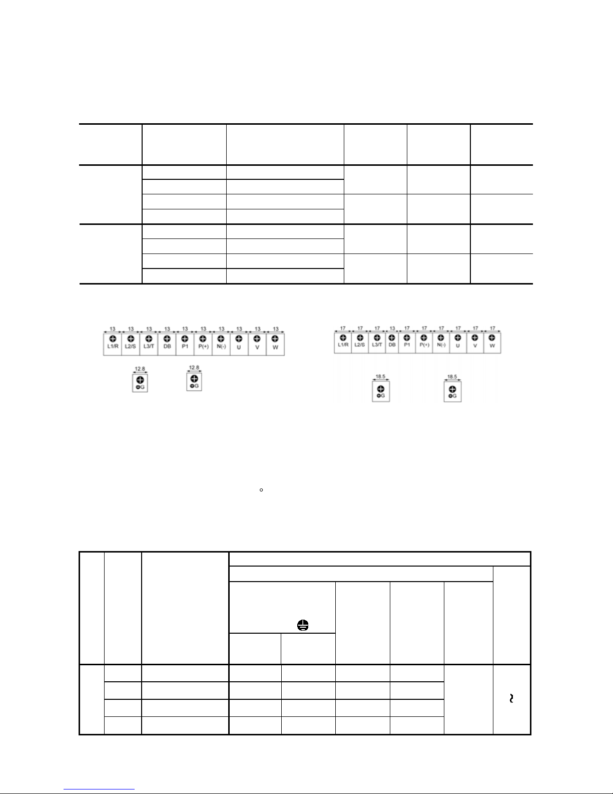
2.3.2 Terminal arrangement and screw specifications
(1) Arrangement of the main circuit terminals
Table 2.3 Main Circuit Terminals
Power
supply
voltage
Nominal ap-
plied motor
(HP)
Inverter type
Terminal
screw size
Tightening
torque
(lb-in)
Refer to:
7.5 FRN0025C2S-2U
10 FRN0033C2S-2U
M5 26.6 Figure E
15 FRN0047C2S-2U
Three-
phase
200 V
20 FRN0060C2S-2U
M6
51.3
Figure
F
7.5 FRN0013C2S-4U
10 FRN0018C2S-4U
M5 26.6 Figure E
15 FRN0024C2S-4U
Three-
phase
400 V
20 FRN0030C2S-4U
M6
51.3 Figure F
Figure E
Figure F
2.3.3 Recommended wire sizes
Table 2.6 lists the recommended wire sizes. The recommended wire sizes for the main circuit terminals for an ambient temperature of 50
C are indicated for two types of wire: HIV single wire (for the
maximum allowable temperature 75°C) (before a sla sh (/)) and IV single wire (for 6 0°C) (after a slash
(/))
Table 2.6 Recommended Wire Sizes
Recommended wire size (AWG) *1
Main circuit
Main circuit power input
[L1/R, L2/S, L3/T]
[L1/L, L2/N]
Grounding [
G]
Power supply voltage
Nomi-
nal
applied
motor
(HP)
Inverter type
w/ DCR*2w/o DCR
Inverter
output
[U, V, W]
DCR
[P1, P (+)]
Braking
resistor
[P (+), DB]
Control
circuit
7.5
FRN0025C2S-2U
14/10 12/ 8 12/10 12/10
10
FRN0033C2S-2U
12/ 8 10/ 6 12 /8 10/ 6
15
FRN0047C2S-2U
10/ 6 6/ 4 8/ 6 8/ 4
Three-phase
200 V
20
FRN0060C2S-2U
6/ 4 4/ 2 6/ 4 6/ 2
14/14
20
16
Phone: 800.894.0412 - Fax: 888.723.4773 - Web: www.clrwtr.com - Email: info@clrwtr.com
Page 3
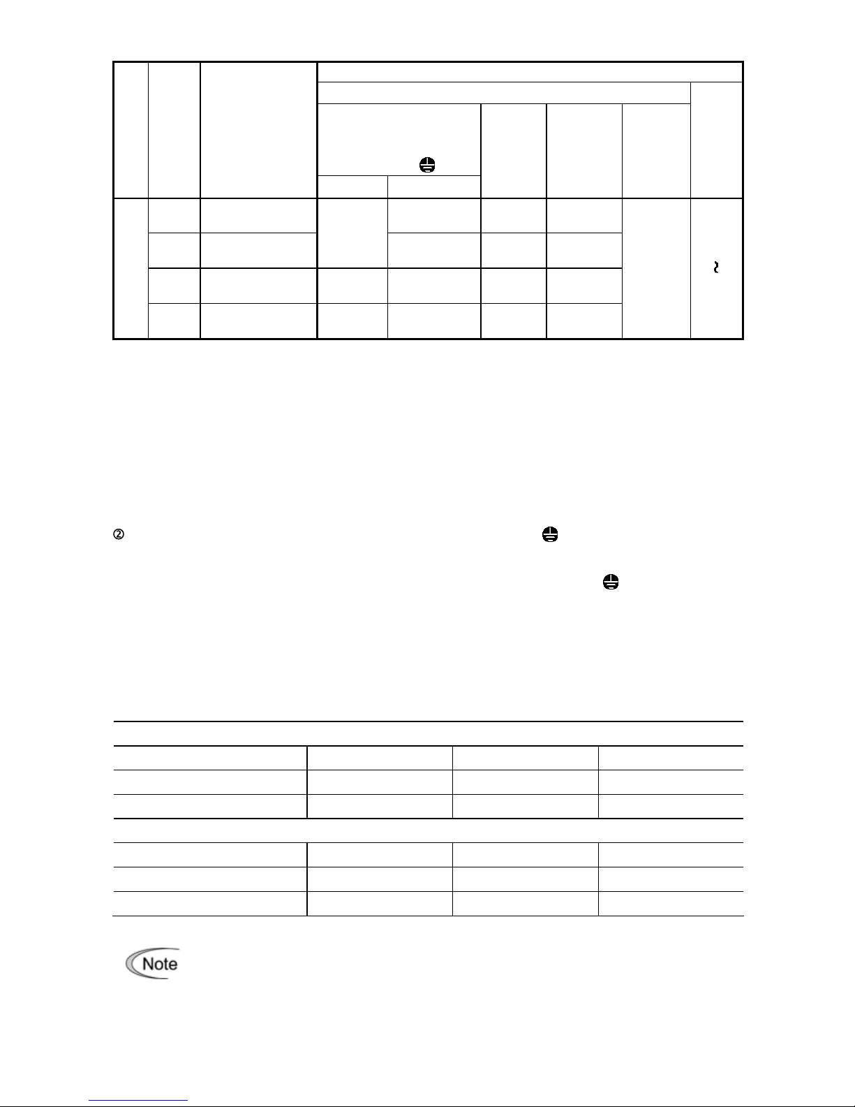
Table 2.6 Recommended Wire Sizes (Continued)
Recommended wire size (AWG) *1
Main circuit
Main circuit power input
[L1/R, L2/S, L3/T]
[L1/L, L2/N]
Grounding [
G]
Power supply voltage
Nomi-
nal
applied
motor
(HP)
Inverter type
w/ DCR w/o DCR *2
Inverter
output
[U, V, W]
DCR
[P1, P (+)]
Braking
resistor
[P (+), DB]
Control
circuit
7.5
FRN0013C2S-4U
14/12
(13)
14/14
(13)
14/14
(13)
10
FRN0018C2S-4U
14/14
(13)
14/10
(11)
14/12
(13)
14/12
(13)
15
FRN0024C2S-4U
14/10
(11)
12 /8
(9)
14/10
(11)
12/10
(11)
Three-phase
400 V
20
FRN0030C2S-4U
12 /8
(9)
10/ 6
(7)
12/ 8
(9)
10 /6
(9)
14/14
(13)
20
16
DCR: DC reactor
*1 Use crimp termina ls covered with an insulated shea th or insulating tube. Recom mended wire sizes are
for HIV
/IV (PVC in the EU).
*2 Wire sizes are calcul ated on the basis of inp ut RMS current under the c ondition that the po wer suppl
y
capacity and impedance are 500 kVA and 5%, respectively.
*3 Insert the DC reactor (DCR) in either of the primary power input lines. Refer to C hapter 10 for more
details.
2.3.5 Wiring for main circuit terminals and grounding terminals
Inverter output terminals, U, V, W and grounding terminal ( G)
1) Connect the three wires of the three-phase motor to terminals U, V, and W, aligning phases each other.
2) Connect the grounding wire of terminals U, V, and W to the grounding terminal (
G).
3) If the cable from the inverter to the motor is very long, a high-frequency current may be generated by stray
capacitance between the cables and resul t in an over current trip o f the inverter, an increase in leakage
current, or a reduction in current indication precision.
When a motor is driven b y a PWM-type inverter, the motor terminals may be subject to surge voltage gen erated by inverter element switching. If the motor cable (with 460 V series motors, in particular) is particularly
long, surge voltage will deteriorate motor insulation. To prevent this, use the following guidelines:
Inverters of 7.5 HP or above
Motor Insulation Level 1000 V 1300 V 1600 V
460 VAC Input Voltage 66 ft (20 m) 328 ft (100 m) 1312 ft (400 m)*
230 VAC Input Voltage 1312 ft (400 m)* 1312 ft (400 m)* 1312 ft (400 m)*
Inverters of 5 HP or below
Motor Insulation Level 1000 V 1300 V 1600 V
460 VAC Input Voltage 66 ft (20 m) 165 ft (50 m) 165 ft (50 m)*
230 VAC Input Voltage 328 ft (400 m)* 328 ft (100 m)* 328 ft (100 m)*
* For this case the cable length is determined by secondary effects and not voltage spiking.
When a motor protective thermal O/L relay is inserted between the inverter and the motor, the
thermal O/L relay may malfunction (particularly in the 460 V series), even when the cabl e
length is 165 ft (50 m) or less. T o correc t, insert a fil ter or red uce the carri er frequenc y. (Use
function code F26 (Motor sound).)
Phone: 800.894.0412 - Fax: 888.723.4773 - Web: www.clrwtr.com - Email: info@clrwtr.com
Page 4
Chapter 5 FUNCTION CODES
5.1 Function Code Tables
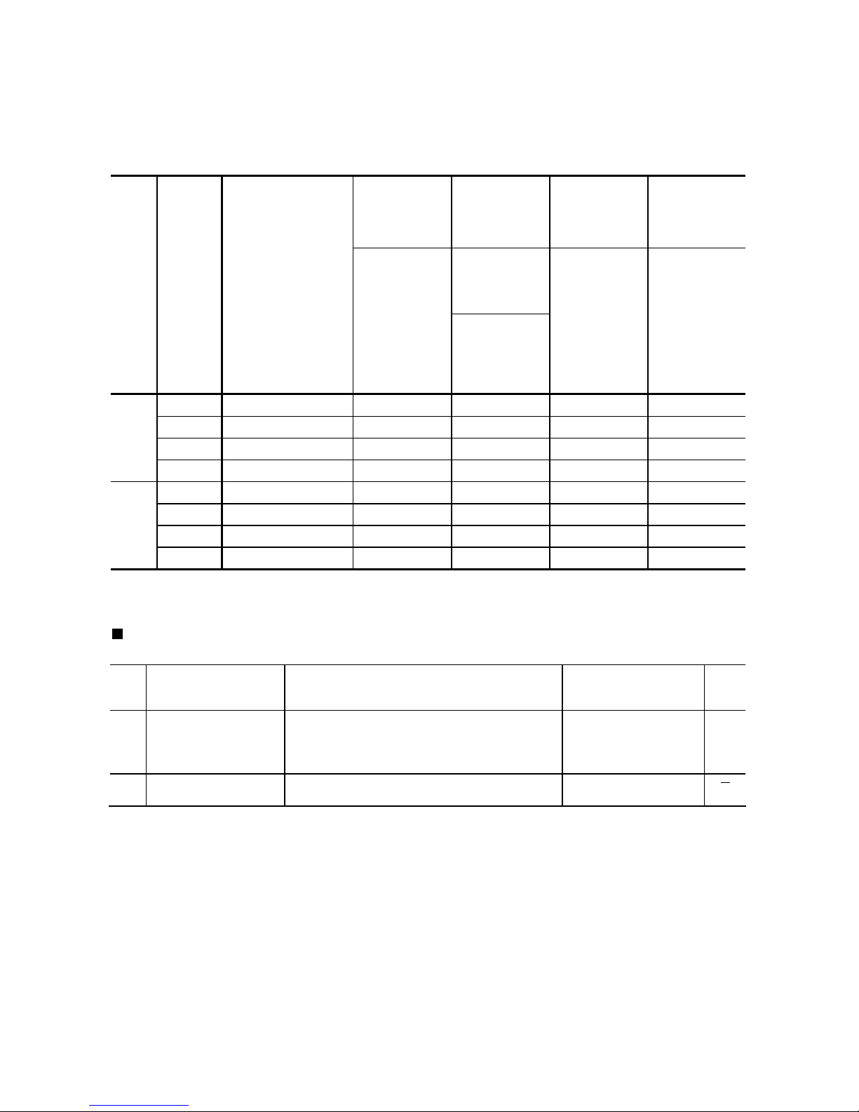
Table A Fuji Standard Motor Parameters
Fuji's standard
torque
boost (%)
Nominal rated
current of
Fuji standard
motor (A)
Nominal rated
capacity of
Fuji standard
motor (kW)
Restart Mode
after Momentary
Power Failure
(s)
Function codes
F11/A07/
E34/E37
Power
supply
voltage
Applicable
motor rat-
ing
(HP)
Inverter type
Function code
F09/A05
Shipping destina-
tion (version)
Function code
P02/A16
Function
code
H13
7.5 FRN0025C2S-2U
4.9
20.06
5.50 0.5
10 FRN0033C2S-2U
4.4
25.72
7.50 0.5
15 FRN0047C2S-2U
3.5
37.21
11.00 1.0
Threephase
200 V
20 FRN0060C2S-2U
2.8
48.50
15.00
1.0
7.5 FRN0013C2S-4U
4.9
10.24
5.50 0.5
10 FRN0018C2S-4U
4.4
12.86
7.50 0.5
15 FRN0024C2S-4U
3.5
18.60
11.00 1.0
Threephase
400 V
20 FRN0030C2S-4U
2.8
24.25
15.00 1.0
The following function code , in the ROM version 0800 or later, the data setting range and the
factory default is change.
Code Name Data setting range Default setting
Refer
to
page:
F44 Current Limiter (Level)
20 to 180 : 3.7kW or below
20 to 200 : 5.5kW or above
(The data is interpreted as the rated output current of the inverter for 100%.)
3.7kW or below : 160
5.5kW or above : 180
5-42
H27
Thermistor for Motor
(Level)
0.00 to 5.00 1.6
Phone: 800.894.0412 - Fax: 888.723.4773 - Web: www.clrwtr.com - Email: info@clrwtr.com
Page 5
5.2 Details of Function Codes
F50, F51
Electronic Thermal Overload Protection for Braking Resistor
(Discharging capability and Allowable average loss)
External Braking Resistors
Standard models
Braking resistor
Continuous braking
(100% braking torque)
Intermittent braking
(Period: 100 s or less)
Power
supply
voltage
Inverter type
Type Qty.
Resistance
(
)
Discharging
capability
(kWs)
Braking
time
(s)
Allowable
average loss
(kW)
Duty
(%ED)
FRN0025C2S-2U
DB5.5-2 20 55
20
0.138
FRN0033C2S-2U
DB7.5-2 15 37 0.188
FRN0047C2S-2U
DB11-2 10 55 0.275
Threephase
200 V
FRN0060C2S-2U
DB15-2
1
8.6 75
10
0.375
5
FRN0013C2S-4U
DB5.5-4 80 55
20
0.138
FRN0018C2S-4U
DB7.5-4 60 38 0.188
FRN0024C2S-4U
DB11-4 40 55 0.275
Threephase
400 V
FRN0030C2S-4U
DB15-4
1
34.4 75
10
0.375
5
10%ED
Braking resistor
Continuous braking
(100% braking torque)
Intermittent braking
(Period: 100 s or less)
Power
supply
voltage
Inverter type
Type Qty.
Resistance
(
)
Discharging
capability
(kWs)
Braking
time
(s)
Allowable
average loss
(kW)
Duty
(%ED)
FRN0025C2S-2U
DB5.5-2C 20 55
20
0.275
FRN0033C2S-2U
DB7.5-2C 15 37 0.375
FRN0047C2S-2U
DB11-2C 10 55 0.55
Threephase
200 V
FRN0060C2S-2U
DB15-2C
1
8.6 75
10
0.75
10
FRN0013C2S-4U
DB5.5-4C 80 55
20
0.275
FRN0018C2S-4U
DB7.5-4C 60 38 0.375
FRN0024C2S-4U
DB11-4C 40 55 0.55
Threephase
400 V
FRN0030C2S-4U
DB15-4C
1
34.4 75
10
0.75
10
Phone: 800.894.0412 - Fax: 888.723.4773 - Web: www.clrwtr.com - Email: info@clrwtr.com
Page 6

Chapter 8 SPECIFICATIONS
8.1 Standard Models
8.1.1 Three-phase 200 V class series
Item Specifications
Type (FRN_ _ _ _ C2S-2U) 0025 0033 0047 0060
Applicable motor rating (HP) *1
7.5 10 15 20
Rated capacity (kVA) *2 9.5 12 17 22
Rated voltage (V) *3 Three-phase, 200 to 240 V (with AVR function)
Rated current (A)
25
(23.5) *10
33.0
(31.0) *10
47.0
(44.0) *10
60.0
(57.0) *10
Overload capability
150% of rated output current for 1 min or 200% of rated output
current for 0.5 min
Output Ratings
Rated frequency (Hz) 50 60 Hz
Phases, voltage, fre-
quency
Three-phase, 200 to 240 V, 50/60 Hz
Voltage and frequency
variations
Voltage: +10 to -15% (Interphase voltage unbalance: 2% or less)
*5, Frequency: +5 to -5%
(w/ DCR) 21.1 28.8 42.2 57.6
Rated current (A) *6
(w/o DCR) 31.5 42.7 60.7 80.0
Input Ratings
Required power supply
capacity (kVA) *7
7.4 10 15 20
Torque (%) *8 20
DC braking
Braking starting frequency*9: 0.0 to 60.0 Hz,
Braking time: 0.0 to 30.0 s, Braking level: 0 to 100%
Braking
Braking transistor Built-in
Applicable safety standards UL508C, IEC 61800-5-1: 2007 (under application)
Enclosure IP20 (IEC 60529:1989), UL open type (UL50)
Cooling method Fan cooling
Mass (lbs)
6.8 6.8 9.8 9.8
*1 Fuji 4-pole standard motors
*2 Refers to the rated capacity assuming the rated output voltage as 220 V for three-phase 200V series.
*3
Output voltages cannot exceed the power supply voltag
e.
*5
2004):3-61800IECto(Refer67
(V)voltageaveragephase-3
(V)eMin.voltag-(V)voltageMax.
(%)unbalancevoltageInterphase
If this value is 2 to 3%, use an optional AC reactor (ACR).
*6 Refers to the estimated value to apply w hen the power supply capacity i s 500 kV A (inv erter capaci ty x 10 when the
inverter capacity exceeds 50 kVA) and the inverter is connected to the %X = 5% power supply.
*7 Refers to the value to apply when a DC reactor (DCR) is used.
*8 Refers to the average br aking torq ue to apply w hen the motor r unning alone decel erates fr om 60 Hz wi th the AVR
control being OFF. (It varies with the efficie ncy of the motor.)
*9 Available only for induction motor drive.
*10The load shall be reduced so that the continuous operating current is the rated current in parentheses or less if the
carrier frequency is set to 4 kHz or above or the ambient temperature exceeds 40°C
104°F .
Phone: 800.894.0412 - Fax: 888.723.4773 - Web: www.clrwtr.com - Email: info@clrwtr.com
Page 7

8.1.2 Three-phase 400 V class series
Item Specifications
Type (FRN_ _ _ _ C2S-4U) 0013 0018 0024 0030
Applicable motor rating (HP) *1 7.5 10 15 20
Rated capacity (kVA) *2 9.9 13 18 22
Rated voltage (V) *3 Three-phase, 380 to 480 V (with AVR function)
Rated current (A) 13.0 18.0 24.0 30.0
Overload capability
150% of rated output current for 1 min or 200% of rated output
current for 0.5 min
Output Ratings
Rated frequency (Hz) 50 60 Hz
Phases, voltage, fre-
quency
Three-phase, 380 to 480 V, 50/60 Hz
Voltage and frequency
variations
Voltage: +10 to -15% (Interphase voltage unbalance: 2% or less)
*5, Frequency: +5 to -5%
(w/ DCR) 10.6 14.4 21.1 28.8
Rated current (A) *6
(w/o DCR) 17.3 23.2 33.0 43.8
Input Ratings
Required power supply
capacity (kVA) *7
7.4 10 15 20
Torque (%) *8 20
DC braking
Braking starting frequency*9: 0.0 to 60.0 Hz,
Braking time: 0.0 to 30.0 s, Braking level: 0 to 100%
Braking
Braking transistor Built-in
Applicable safety standards UL508C, IEC 61800-5-1: 2007 (under application)
Enclosure IP20 (IEC 60529:1989), UL open type (UL50)
Cooling method Fan cooling
Mass (lbs)
6.8 6.8 9.8 9.8
*1 Fuji 4-pole standard motors
*2 Refers to the rated capacity assuming the rated output voltage as 440 V for three-phase 400V series.
*3 Output voltages cannot exceed the power supply voltage.
*5
2004):3-61800IECto(Refer67
(V)voltageaveragephase-3
(V)eMin.voltag-(V)voltageMax.
(%)unbalancevoltageInterphase
If this value is 2 to 3%, use an optional AC reactor (ACR).
*6 Refers to the estimated value to apply when the power supply capacity i s 500 kV A (inv erter capacity x 10 when the
inverter capacity exceeds 50 kVA) and the inverter is connected to the %X = 5% power supply.
*7 Refers to the value to apply when a DC reactor (DCR) is used
.
*8
Refers to the average braking torque t o apply when the motor runni ng al one decel erates fro m 60 Hz wi th the AV
R
control being OFF. (It varies with the efficiency of the motor.)
*9 Available only for induction motor drive.
Phone: 800.894.0412 - Fax: 888.723.4773 - Web: www.clrwtr.com - Email: info@clrwtr.com
Page 8

8.4 External Dimensions
8.4.1 Standard models
Unit inch [mm]
Power supply
voltage
Inverter type
FRN0025C2S-2U
Three-phase
200 V
FRN0033C2S-2U
FRN0013C2S-4U
Three-phase
400 V
FRN0018C2S-4U
Power supply
voltage
Inverter type
FRN0047C2S-2U
Three-phase
200 V
FRN0060C2S-2U
FRN0024C2S-4U
Three-phase
400 V
FRN0030C2S-4U
Phone: 800.894.0412 - Fax: 888.723.4773 - Web: www.clrwtr.com - Email: info@clrwtr.com
Page 9

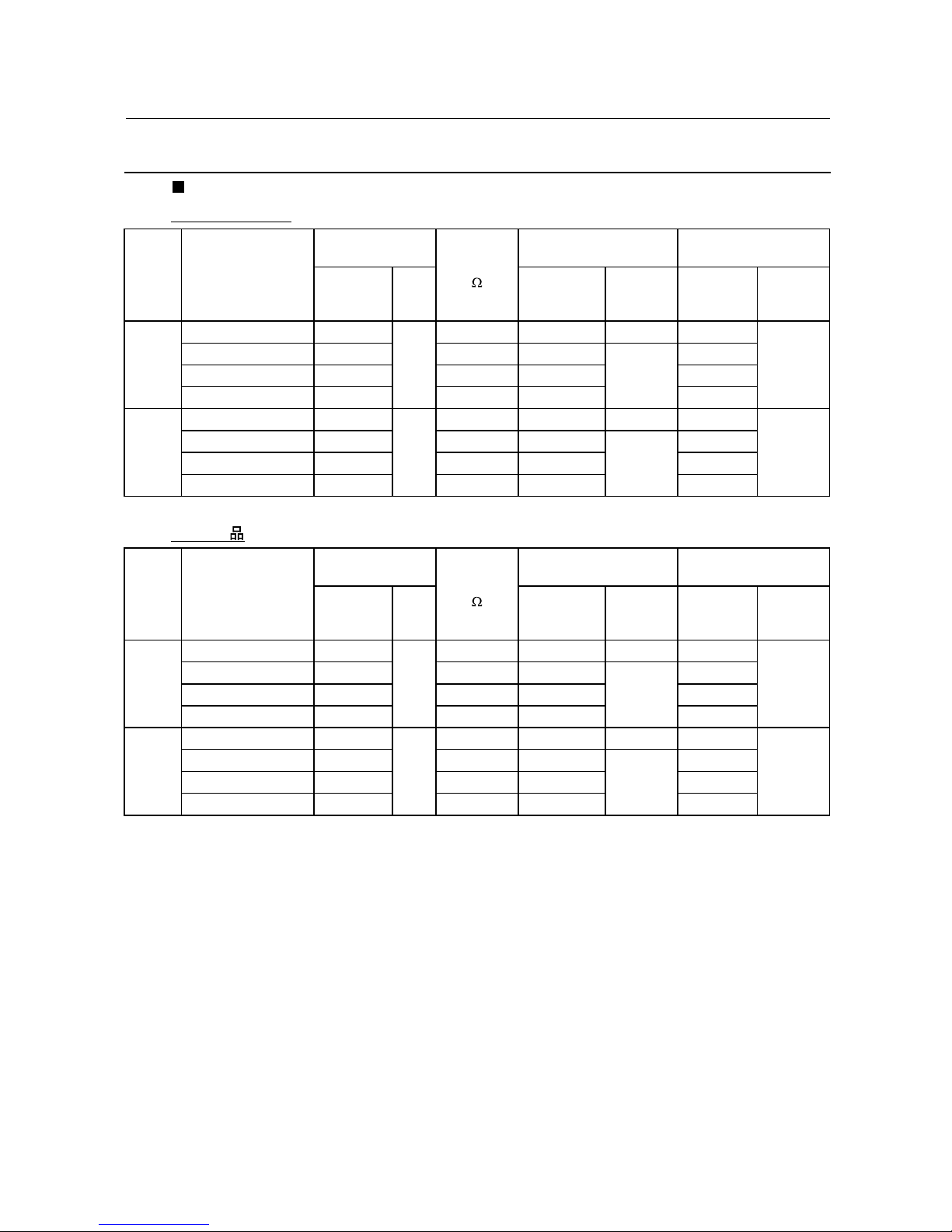
Chapter 9 LIST OF PERIPHERAL EQUIPMENT AND OPTIONS
Name of peripheral
equipment
Function and application
Main peripheral equipment
Molded case
circuit breaker
(MCCB)
Residual-currentoperated protective device (RCD)
/Earth leakage
circuit breaker
(ELCB)
*
*
with overcu
rrent
protection
MCCBs are designed to protect the power circuits between the power control
board and inverter’s main terminals (L1/R, L2/S and L3/T for three-phase
power, L1/L and L2/N for single-phase power) from overload or sh ort-circuit
which in turn prevents secondary disaste rs caused by the inverter malfunctioning.
RCDs/ELCBs function in the same way as MCCBs. Use the MCCBs and
RCDs/ELCBs that satisfy the recommended rated current listed below.
Recommended rated current (A) of
MCCB and RCD/ELCB
Power
supply
voltage
Applicable
motor
rating
(HP)
Inverter type
w/ DC reactor w/o DC reactor
7.5
FRN0025C2S-2U 30 50
10
FRN0033C2S-2U 40 75
15
FRN0047C2S-2U 50 100
Three-
phase
200 V
20
FRN0060C2S-2U 75 125
7.5
FRN0013C2S-4U
15
30
10
FRN0018C2S-4U
20
40
15
FRN0024C2S-4U
30
50
Three-
phase
400 V
20
FRN0030C2S-4U
40
60
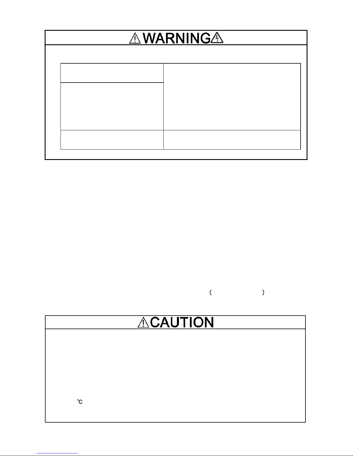
When connecting the inverter to the power supply, add a recommended
molded case circuit breaker (MCCB) or a residual-curre nt-opera ted protective device (RCD)/earth leakage circuit breaker (ELCB)* in the path of power
supply. Do not use the devices with the rated current out of the recommended range. *With overcurrent protection
Fire could occur.
Select the MCCB or RCD/ELCB with appropriate rated current and breaking
capacity according to the power supply capacity.
Chapter 10 APPLICATION OF DC REACTORS (DCRs)
Since the "Japanese Guideline for Suppressing Harmonics in Home and General-purpose Appliances" issued by the Mini stry of Interna tional T rade and Industry (Currently the Ministry of Econom y,
Trade and Industry) was revised in January 2004, the general-purpose inverters have no longer
been subject to the guideline. Individual inverter manufacturers have voluntarily employed harmonics suppression measures. It is recommended that DC reactors (DCRs) specified in Table 10.1
be connected to the FRENIC-Mini series of inverters.
Phone: 800.894.0412 - Fax: 888.723.4773 - Web: www.clrwtr.com - Email: info@clrwtr.com
Page 10

Table 10.1 List of DC Reactors (DCRs)
Power
supply
voltage
Nominal applied
motor (HP)
Applicable inverter type DCR type
7.5 FRN0025C2S-2U
DCR2-5.5
10 FRN0033C2S-2U
DCR
2-7.5
15 FRN0047C2S-2U
DCR2-11
Threephase
200 V
20 FRN0060C2S-2U
DCR
2-15
7.5 FRN0013C2S-4U
DCR4-5
.5
10 FRN0018C2S-4U
DCR4-7
.5
15 FRN0024C2S-4U
DCR
4-1 1
Threephase
400 V
20 FRN0030C2S-4U
DCR
4-15
Chapter 11 COMPLIANCE WITH STANDARDS
11.1 Compliance with European Standards
The CE marking on Fuji products indicates that they comply with the essential requirements of the
Electromagnetic Compatibility (EMC) Directive 2004/108/EC issued by the Council of the European
Communities and Low Volta ge Directive 2006/95/EC.
Inverters that bear a CE marking are compliant with the Low Voltage Directive.
The products comply with the following standards:
Low Voltage Directive EN61800-5-1: 2007
EMC Directives EN61800-3: 2004 +A1: 2012
Immunity: Second environment (Industrial)
Emission: Category C2
(Applicable only when an optional EMC-compliant filter
is attached)
CAUTION
The FRENIC-Mini series of inverters are categorized as a "restricted sales distribution class" of the
EN61800-3. When you use these products with any home appliances or office equipment, you may
need to take appropriate countermeasures to reduce or eliminate any noise emitted from these
products.
11.2 Compliance with EMC Standard
11.2.2 Recommended installation procedure
In case an outboard, EMC-compliant (optional) is used
If noise from the inverter exceeds the permissible level, enclose the inverter and its peripherals
within a metal pane.
For details, refer to the FRENIC-Mini Instruction Manual (INR-SI47-1745-E), Chapter 11
Sec-
tion
11.2 "Comp liance with EMC Standard."
Phone: 800.894.0412 - Fax: 888.723.4773 - Web: www.clrwtr.com - Email: info@clrwtr.com
Page 11

11.2.3 Leakage current of EMC-complaint filter (optional)
Table 11.1 Leakage Current of EMC-compliant Filter (optional)
Inverter type Leakage current (mA)
*1 to *4
For Japan For other countries
Filter type
Normal Worst
FRN5.5C2S-2J FRN0025C2S-2U
FRN7.5C2S-2J FRN0033C2S-2U
FS5956-53-52
11
*1
11
*1
FRN11C2S-2J FRN0047C2S-2U
FRN15C2S-2J FRN0060C2S-2U
EFL-15SP-2
20
*1
20
*1
FRN5.5C2S-4J
FRN0013C2S-4U
FRN7.5C2S-4J
FRN0018C2S-4U
FS21559-24-07-1 4
*2
59
*2
FRN11C2S-4J
FRN0024C2S-4U
FRN15C2S-4J FRN0030C2S-4U
FS21312-44-07 4
*3
167
*3
*1) The values are calculated assuming the power supplies of three-phase 240 V (50 Hz).
*2) The values are calculated assuming the power supplies of three-phase 400 V (50 Hz).
*3) The values are calculated assuming the power supplies of three-phase 480 V (50 Hz).
*4) The worst condition includes a phase loss in the supply line.
11.4 Compliance with the Low Voltage Directive in the EU
11.4.1 General
General-purpose inverters are regulated by the Low Voltage Directive in the EU. Fuji Electric has
obtained the proper certification for the Low V oltage Directi ve from the offi cial inspection agency. Fuji
Electric states that all our inverters with CE marking are compliant with the Low Voltage Directive.
11.4.2 Points for consideration when using the FRENIC-Mini series in a system to be
certified by the Low Voltage Directive in the EU
If you want to use the FRENIC-Mini series of inverters in systems/equipment in the EU, refer to the
guidelines given below.
Phone: 800.894.0412 - Fax: 888.723.4773 - Web: www.clrwtr.com - Email: info@clrwtr.com
Page 12

Conformity to the Low Voltage Directive in the EU
If installed according to the guidelines given below, inverters marked with CE are considered as
compliant with the Low Voltage Directive 2006/95/EC.
12. Use wires listed in IEC60364-5-52.
Recommended wire size (mm2 )
*1
Rated current (A)
of
MCCB or RCD/ELCB
*2
Main circuit
power input
[L1/R, L2/S, L3/T]
[L1/L, L2/N]
Grounding [
G]
Power supply voltage
Appli-
cable
motor
rating
(HP)
Inverter type
w/ DCR
*3
w/o DCR
w/ DCR*3w/o DCR
*2
Inverter
output
[U, V,
W]
*2
DCR
[P1,
P (+)]
Braking
resistor
[P (+),
DB]
Control
circuit
(30A,
30B,
30C)
7.5
FRN0025C2S-2U 30 50 4.0 6.0 4.0 4.0
10
FRN0033C2S-2U 40 75 6.0 10 6.0 6.0
15
FRN0047C2S-2U 50 100 10 16 10 16
3-phase 200 V
20
FRN0060C2S-2U 75 125 16 25 16 25
0.5
7.5
FRN0013C2S-4U 15 30 2.5
10
FRN0018C2S-4U 20 40
2.5
4.0
2.5 2.5
15
FRN0024C2S-4U 30 50 4.0 6.0 4.0 4.0
3-phase 400 V
20
FRN0030C2S-4U 40 60 6.0 10 6.0 6.0
0.5
MCCB: Molded case circuit breaker
RCD: Residual-current-operated protective device
ELCB: Earth leakage circuit breaker
*1 The frame size and model of the MCCB or RCD/ELCB (with overcurrent protection) will vary, de-
pending on the power transformer capacity. Refer to the related technical documentation for details.
*2 The recommen ded wire size for main circuits is for the 70
C 600V PVC wires used at an ambient
temperature of 40
C.
*3 In the case of no DC reactor, the wire sizes are determined on the basis of the effective input current
calculated under the condition that the power supply capacit y and impedance are 500 kVA and
5%, respectively.
Phone: 800.894.0412 - Fax: 888.723.4773 - Web: www.clrwtr.com - Email: info@clrwtr.com
Page 13

Conformity to the Low Voltage Directive in the EU (Continued)
13. To prevent the risk of hazardous accidents that could be caused by damage of the inverter,
install the specified fuses in the supply side (primary side) according to the following tables.
- Breaking capacity: Min. 10 kA
- Rated voltage: Min. 500 V
Power
supply
voltage
Nominal
applied
motor (HP)
Inverter type
Fuse rating
(A)
7.5
FRN0025C2S-2U
125(IEC60269-4)
10
FRN0033C2S-2U
160(IEC60269-4)
15
FRN0047C2S-2U
160(IEC60269-4)
Three-phase
200V
20
FRN0060C2S-2U
200(IEC60269-4)
7.5
FRN0013C2S-4U
80(IEC60269-4)
10
FRN0018C2S-4U
80(IEC60269-4)
15
FRN0024C2S-4U
125(IEC60269-4)
Three-phase
400V
20
FRN0030C2S-4U
160(IEC60269-4)
14. Use this inverter at the following power supply system.
Phone: 800.894.0412 - Fax: 888.723.4773 - Web: www.clrwtr.com - Email: info@clrwtr.com
Page 14
Conformity to the Low Voltage Directive in the EU (Continued)
*1 Use this inverter at the following IT system.
Non-earthed (isolated from earth) IT
system
IT system which earthed neutral
by an impedance
Can be used.
In this case the insu l ation between the control
interface and the main circuit of the inverter is
basic insulation.
Thus do not connect SELV circuit from external
controller directly (make connection using a
supplementary insulation.).
Use an earth fault detector able to disconnect
the power within 5s after the earth fault occurs.
Corner earthed / Phase-earthed IT
system by an impedance
Can not be used
*2 Cannot apply to Corner earthed / Phase-earthed TT system of 400V type.
11.5 Compliance with UL Standards and Canadian Standards (cUL certification)
11.5.1 General
Originally, the UL standards were established by Underwriters Laboratories, Inc. as private criteria
for inspections/investigations pertainin g to fire/accident insurance in the USA. Later , these standards
were authorized as the official standards to protect operators, service personnel and the general
populace from fires and other accidents in the USA.
cUL certification means that UL has given certification for products to clear CSA Standards. cUL
certified products are equivalent to those compliant with CSA Standards.
11.5.2 Considerations when using FRENIC-Mini in systems to be certified by UL and cUL
To use the FRENIC-Mini series of inverters as a part of UL Standards or CSA Standards (cUL certified) certified product, refer to the guidelines given below.
Conformity to UL standards and Canadian standards cUL certification
If installed according to th e guidelines given below, inverters marked with UL/cUL are con sidered a s
compliant with the UL and CSA (cUL certified) standards.
Integral solid state short circuit protection does not provide branch circuit protection. Branch
circuit protection must be provided in accordance with the National Electrical Code and any
additional local codes.
1. Solid state motor overload prote ction ( m otor protection by electr onic thermal ov erload relay )
is provided in each model.
Adjust function codes F10 to F12 and H89 to set the protection level.
2. Connect the power supply satisfying the characte ristics show n in the table below as an input
power supply of the inverter. (Short circuit rating)
3. Use 75
Cu wire only.
4. Use Class 1 wire only for control circuits.
Phone: 800.894.0412 - Fax: 888.723.4773 - Web: www.clrwtr.com - Email: info@clrwtr.com
Page 15

Conformity to UL standards and Canadian standards cUL certification
Short circuit rating
When protected by class J fuses, su it able for use on a circui t capable of delivering not more
than B rms symmetrical amperes, A volts maximum.
Power
supply
voltage
Inverter type
Power supply max. voltage
Volts
Power supply current
Amperes
FRN0025C2S-2U
FRN0033C2S-2U
FRN0047C2S-2U
Three-phase
200V
FRN0060C2S-2U
240VAC 100,000 A or less
FRN0013C2S-4U
FRN0018C2S-4U
FRN0024C2S-4U
Three-phase
400V
FRN0030C2S-4U
480VAC 100,000 A or less
5. Install UL certified fuses rated 600Vac between the power supply and the invert er, referrin g to
the table below.
Required torque
Ib-in (N
m)
Wire size
AWG or kcmil(mm2)
Control circuit Control circuit
Power
supply
voltage
Inverter type
Main
terminal
*1
TERM1
*2
TERM2-1
TERM2-2
*3
Main
terminal
*1
TERM1
*2
TERM2-1
TERM2-2
Class J fuse cur-
rent(A)
FRN0025C2S-2U 60
FRN0033C2S-2U
27
(3.0)
8
(8.4)
75
FRN0047C2S2U
6
(13.3)
100
Three-phase
200V
FRN0060C2S-2U
51.3
(5.8)
3.5
(0.4)
1.7
(0.2)
4
(21.2)
6
(13.3)
20
(0.5)
150
FRN0013C2S-4U
12
(3.3)
10
(5.3)
30
FRN0018C2S-4U
27
(3.0)
10
(5.3)
40
FRN0024C2S-4U 60
Three-phase
400V
FRN0030C2S-4U
51.3
(5.8)
3.5
(0.4)
1.7
(0.2)
8
(8.4)
20
(0.5)
70
Phone: 800.894.0412 - Fax: 888.723.4773 - Web: www.clrwtr.com - Email: info@clrwtr.com
Page 16

Conformity to UL standards and Canadian standards cUL certification (Continued)
*1 Denotes the relay contact terminals for [30A], [30B] and [30C].
*2 Denotes control terminals except for [30A], [30B] and [30C].
*3 Values in [ ] mean the size(AWG) of Grounding wire if exist.
6. To comply with CSA for 400VAC input models, transient surge suppressio n shall be installed
on the line side o f this equipme nt and shall be rated 278V ( phase to gro und), 480V (phase to
phase), suitabl e f or over vol ta g e ca te gor y 3, and s hal l p ro vid e p ro t ecti on for a rat ed im pu ls e
withstand voltage peak of 4k
V.
7. All models rated 380-480 V input voltage ratings shall be connected to TN-C system power
source, i.e. 3-phase, 4-wire, wye (480Y/277V), so that the phase-to-ground rated system
voltage is limited to 300V maxi
mum.
8
. Maximum surrounding air temperature rating of 50 ºC
.
Compact Inverter
Instruction Manual
Supplement for FRN-C2S-2U/4U 7.5 to 20HP
First Edition, March 2014
Fuji Electric Co., Ltd.
The purpose of this instruction manual is to provide accurate information in handling, setting up and
operating of the FRENIC-Mini series of inverters. Please feel free to send your comments regarding
any errors or omissions you may have found, or any suggestions you may have for generally improving the manual.
In no event will Fuji Electric Co., Ltd. be liable for any direct or indirect damages resulting from the
application of the information in this manual.
Phone: 800.894.0412 - Fax: 888.723.4773 - Web: www.clrwtr.com - Email: info@clrwtr.com
 Loading...