

Page 1
Instruction Manual for FD5000 Ser ies UV-33681e 12/12
Instruction Manual for FD5000 Ser ies 1/12
FD 5 X X X - X X
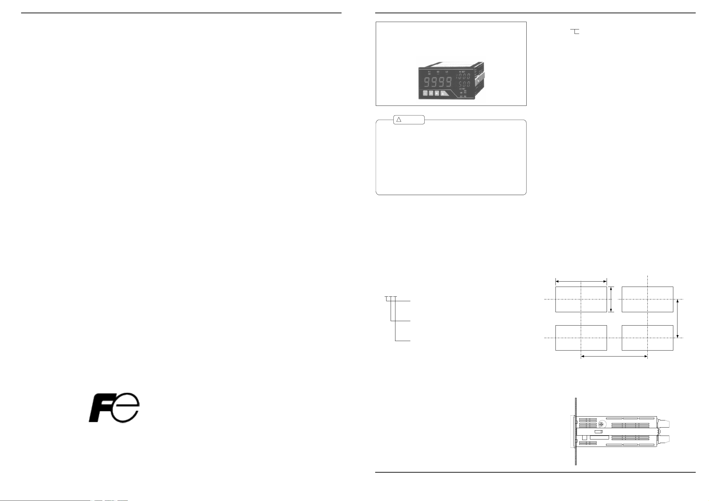
MODEL FD5000 SERIES
INSTRUCTION MANUAL
!
Caution
(1) Do not apply a voltage or current exceeding the maximum allowable
value; otherwise, it may damage the equipment.
(2)
Use a power voltage within the operation range; otherwise, it may result
in a fire, electrical shock, or malfunction.
(3) The contents of this manual are subject to change without notice.
Although the contents of this manual have been prepared with extra
(4)
care, if you have any questions, or find errors or missing information,
contact the sales agent from which you purchased the product or Fuji
Electric Instruments Co.,Ltd.
After reading this manual thoroughly, keep it in a convenient place for
(5)
future reference.
The mark on a label shows the measurement tail range of the input
(6)
specification of 8.1. clause.
1. Before Using the Product
Thank you for purchasing the FD5000 series. This manual should be passed on to
the person who operates the product. Examine the product for damage caused by
transportation or any other defects. If you find any damage or defects, contact
the sales agent from which you purchased the product or Fuji Electric Instru-
ments Co., Ltd.
1.1 Model Codes
The model lineup of the FD5000 series is shown below. Check that the model
code and specifications of your product match those you specified when order-
ing.
2. Mount ing the Product
2.1 Dimensions for Cutting Panel
Cut the panel for mounting according to the following dimensions.
Input unit
01: DC voltage measuring unit
(range 11: ±99.99 mV)
02: DC voltage measuring unit
(range 12: ±999.9 mV ; range 13: ±9.999 V)
(range 14:±99.99 V ; range 15: ±600.0 V)
03: DC current measuring unit
(range 23: ±9.999 mA; range 24: ±99.99 mA)
(range 25: ±999.9 mA)
04: AC voltage measuring unit (average rms)
(range 11: 99.99 mV; range 12: 999.9 mV)
(range 13: 9.999 V)
05: AC voltage measuring unit (average rms)
(range 14: 99.99 V; range 15: 600.0 V)
06: AC voltage measuring unit (true rms)
(range 11: 99.99 mV; range 12: 999.9 mV)
(range 13: 9.999 V)
07: AC voltage measuring unit (true rms)
(range 14: 99.99 V; range 15: 600.0 V)
08: AC current measuring unit (average rms)
(range 23: 9.999 mA; range 24: 99.99 mA)
(range 25: 999.9 mA)
09: AC current measuring unit (average rms)
(range 26: 5 A)
10: AC current measuring unit (true rms)
(range 23: 9.999 mA; range 24: 99.99 mA)
(range 25: 999.9 mA)
11: AC current measuring unit (true rms)
(range 26: 5 A)
12: Resistance measuring unit
13: Temperature measuring unit (TC)
14: Temperature measuring unit (RTD)
15: Frequency measuring unit
(inputs: open collector, logic, and magnet)
16: Frequency measuring unit(input: 50 to 600 Vrms)
17: Strain gauze input unit (load cell)
18: Process signal measuring unit (4 to 20 mA or 1 to 5 V)
+0.8
92
-0
e-Front runners
Fuji Electric Systems Co.,Ltd.
International Sales Dept.
No.1,Fuji-machi,Hino-city,Tokyo,191-8502 Japan
Phone +81-42-585-6201,6202
Fax +81-42-585-6187
FD 5 X X X - X X
Power unit
1: 100 to 240 V AC ±10%
2: 9 to 60 V DC
Display unit
1: Single display
2: Multi display
Output unit
0: None
1: Comparison
2: Analog
3: RS-232C
4: RS-485
5: Comparison and analog
6: Comparison, analog, and RS-232C
7: Comparison, analog, and RS-485
45
+0.6
-0
70 mm
min.
120 mm min.
2.2 Mou nting the Prod uct to the Panel
To mount the FD5000 to the panel, remove its fittings and insert it through the
hole in the front of the panel. From the back of the panel, fix the product to the
panel with the fittings.
(UU-33 554e)
2006.0 3
Fuji Electric Systems Co.,Ltd
Page 2
Instruction Manual for FD5000 Ser ies 2/12
Comparison
Serial
Instruction Manual for FD5000 Ser ies
11/12
!
Caution
(1) Mount the product to a panel that is strong enough to hold the product.
If the panel is not strong enough or the product is not fixed tightly, it
may fall down and cause injury.
(2) The FD5000 does not have a power switch, and will thus be immediately
ready for operation upon connecting it to a power supply.
(3) If the product is installed inside other equipment, provide sufficient heat
dissipation to ensure that the temperature inside the equipment does
not exceed 50℃.
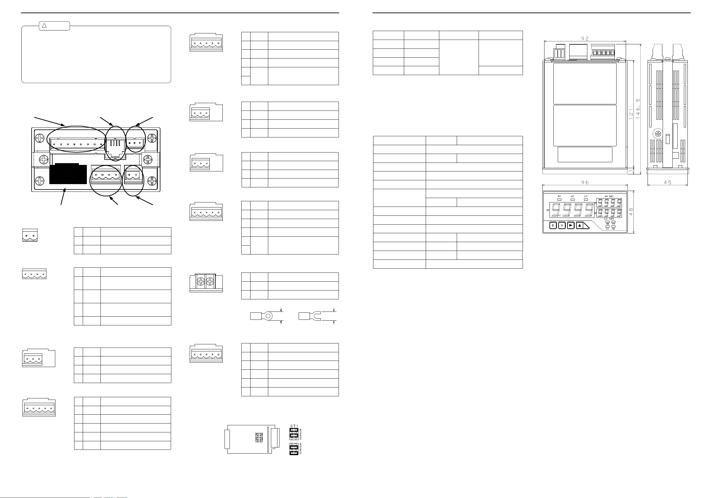
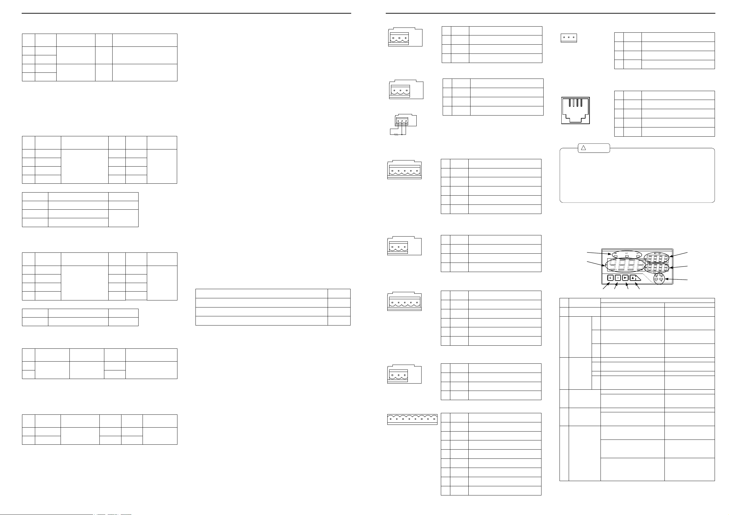
3. Terminal Arrangement
output
12 13 14 15 1 6 1 7 1 8 19
communication
6 7 8 9 10 11
Input (the shape depends on the unit.)
3.1 Power
No. Name Description
Power terminal without polarity for both
DC and AC
Power terminal without polarity for both
DC and AC
10 11
10 POWER
11 POWER
3.2 Ext ernal Cont rols
Name Description
No.
6 7 8 9
6 HOLD
7 DZ
89PH
Control for hold function. Enabled when
short-circuited or at the same potential as
COM.
Control for digital zero function. Enabled
when short-circuited or at the same
potential as COM.
Control for peak hold function. Enabled
when short-circuited or at the same
potential as COM.
COM
Common for all external control terminals.
3.3 Input Signa ls
3.3.1 DC Volta ge Measu ring Unit (Range 11)
Name Description
No.
1 HI Positive input terminal
1 2 3
3.3.2 DC Volt age Measur ing Unit (Ra nge 12)
1 2 3 4 5
2 NC Do not connect this terminal.
3 LO
No.
1 12
2 13
3 14
4 15
5 LO Negative input terminal
Negative input terminal
Name Description
Positive input terminal for range 12
(±999.9 mV)
Positive input terminal for range 13
(±9.999 V)
Positive input terminal for range 14
(±99.99 V)
Positive input terminal for range 15 (±300
V)
202122
23
External
control
Analog output
24 2 5 26
Power
connector
3.3.3 DC Cur rent Measur ing Unit
Name Description
No.
Positive input terminal for range 23
(±9.999 mA)
Positive input terminal for range 24
(±99.99 mA)
Positive input terminal for range 25
(±999.9 mA)
LO5Negative input terminal
1 2 3 4 5
1 23
2 24
3 25
4
3.3.4 AC Volta ge Measu ring Unit (Ranges 11 to 13)
Name Description
No.
Positive input terminal for ranges 11
(99.99 mV) and 12(999.9 mV)
Positive input terminal for range 13 (9.999
V)
LO
Common input terminal
1 2 3
1 11-12
2 13
3
3.3.5 AC Volta ge Measu ring Unit (Ranges 14 and 15)
Name Description
No.
Positive input terminal for range 14 (99.99
V)
Positive input terminal for range 15 (300
V)
LO
Common input terminal
1 2 3
1 14
2 15
3
3.3.6 AC Cur rent Measur ing Unit (Ranges 23 t o 25)
Name Description
No.
Positive input terminal for range 23 (9.999
mA)
Positive input terminal for range 24 (99.99
mA)
Positive input terminal for range 25 (999.9
mA)
LO5Negative input terminal
1 2 3 4 5
1 23
2 24
3 25
4
3.3.7 AC Cur rent Measur ing Un it (Range 26)
Name DescriptionNo.
1 HI Input terminal
1 2
2 LO Input terminal
Applicable solderless terminals
min.
5.8 mm
3.3.8 Resistan ce Measurin g Unit
Name Description
No.
1 HI Input terminal for all ranges
1 2 3 4 5
2 LO
3 +S
4
Input terminal for all ranges
Constant current for four-wire resistance
measurement(positive)
Constant current for four-wire resistance
-S
measurement(negative)
Common terminal (grounding terminal for
LO5
input circuit)
※Set to the 4-wire system when shipped.
When changing to the 2-wire system, locate
the ST1 socket on the resistance measurement
unit to the “2” positions.
4-wire
2-wire
8.3.2 Analog Output
8.4 Exter nal Dimensions
Output type Load resistance Accuracy Ripple
0 to 1V
0 to 10V
1 to 5V
4 to 20mA
10kΩ or more
10kΩ or more
10kΩ or more
550Ω or less
±(0.5% of FS)
±50mVp-p
±25mVp-p
Note: The ripple ratings for the 4-20 mA output are when the load resistance of
250Ω and the output current of 20 mA are applied.
Conversion system:PWM conversion
:
Equivalent to 13 bitsResoluton
Scaling:Digital scaling
Response speed:About 0.5 second
8.3.3 Communicating F unct ion
RS-232C RS-485
Synchronization system
Start and stop synchronization
Full duplexCommunication system
(Polling selecting system)
Two-wire half duplex
Communication rate 38400bps/19200bps/9600bps/4800bps/2400bps
Start bit 1bit
Data length
Error detection
Even parity/odd parity/non-parity
7 bits/8 bits
BCC (block, check, and character)
check sum
Stop bit
Character code
Communication control
procedure
Signal name used TXD,RXD,SG
Number of connectable
units
1
Line length 15m
Delimiter CR+LF/CR
1 bit/2 bits
ASCII code
No procedure
Non-inversion (+)
and inversion (-)
1 Up to 31 meters
Up to 500 m (total)
In EN/IEC conformity,it is unber 30m.
9. War r anty and After-service
9.1 War r anty
The warranty period shall be one year from the date of delivery. Any failure that
arises during this period and the cause thereof is judged to be obviously attribut-
able to Fuji Electric Instruments Co., Ltd. shall be remedied at no cost.
9.2 After-service
This product is manufactured, tested, inspected, and then shipped under
stringent quality control. Should the product fail, however, contact (or send
the product to) your vendor or Fuji Electric Instruments directly. (It is
min.
5.8 mm
advisable that you send a memo describing the failure in as much detail as
possible along with the product returned.)
Page 3
Instruction Manual for FD5000 Ser ies 10/12
8.1.14 Temper at ur e Measu ring Unit (RT D)
Input
Range
sensor
PA
PT100Ω
JPA
JPt100Ω
PB
PT100Ω
JPB
JPt100Ω
Input circuit : Single ended type
Operating system : ΔΣ conversion
Maximum sampling rate : 12.5 times per second
Current through RTD : About 1 mA
External resistance : 10Ω or less per wire
Linearizer : Digital linearizer
Burnout alarm : It blinks by ---- display.
Indication
-100.0 to 199.9℃
(-148.0 to 391.8°F)
-100 to 600℃
(-148 to 1112°F)1℃(1°F)
Highest
resolution
0.1℃
(0.1°F)
Accuracy
±(0.15% of FS)
±(0.3% of FS)
8.1.15 Fr equency Measur ing Unit (open collector, logic, and magnet)
Measurement
Range Indication
Open collector
range
11
0.1 to 200Hz
12
1 to 2000Hz
13
0.01 to 20kHz
14
0.1 to 200kHz
Input type Input voltage lebel
Logic
Magnet
Pre-scale : 0.001 to 5
Frequency division : 1 to 100
LO : 1V or less (5V : 4.7kΩ pull up)
LO : 1V or less,HI : 2.5 to 15V
0.3 to 30Vp-p
Duty ratio : 50%
Highest
Renewal time
resolution
of a display
0.1Hz
1Hz
10Hz
100Hz
Maximum
permissible input
30V
15V
10s
1s
100ms
10ms
Accuracy
±(0.2% of FS)
8.1.16 Fr equency Measur ing Unit (500 Vr ms)
Measurement
Range Indication
range
11
0.1 to 200Hz
12
1 to 2000Hz
13
0.01 to 20kHz
14
0.1 to 200kHz
Input type Input voltage lebel
Voltage 500Vrms
Pre-scale : 0.001 to 5
Frequency division : 1 to 100
50 to 500Vrms
Duty ratio : 50%
Highest
Renewal time
resolution
of a display
0.1Hz
1Hz
10Hz
100Hz
Maximum
permissible input
10s
1s
100ms
10ms
Accuracy
±(0.2% of FS)
8.1.17 Strain Gage Unit
Sensor
Zero adjusting range Span adjusting range
power
5V
-0.3 to +1mV/V
10V
Input circuit : Single ended type
Operating system : ΔΣ conversion
Maximum sampling rate : 12.5 times per second
Noise rejection ratio : NMR (normal mode rejection) 50 dB or more (50 or 60 Hz)
1 to 3mV/V
Highest
resolution
0.5μV/digit
1μV/digit
Accuracy
±(0.1% of FS +2digit)
8.1.18 Pr ocess Signal Measur ing Unit
Measurement
Range
Input circuit : Single ended type
Operating system : ΔΣ conversion
Maximum sampling rate : 12.5 times per second
Noise rejection ratio : NMR (normal mode rejection) 50 dB or more (50 or 60 Hz)
range
1V 1 to 5V
2A 4 to 20mA
Indication
Offset : ±9999
Full scale : 0 to ±9999
impedance
About
100MΩ
About
Input
10Ω
Maximum
permissible
input
±100V
±100mA
Accuracy
±(0.2% of FS)
8.2 Common Specifications
Display
Polarity indication
Indication range
Over-range alarm
Decimal point:Can be set at an arbitrary digit.
Zero indication
External control
Operating temperature and humidity range:0 to 50℃, 35 to 83% RH
Storage temperature and humidity range
Power supply
Power consumption
External dimensions
Weight
Withstand voltage
Withstand voltage
Withstand voltage
Insulation resistance
Conformity standard
Grounding environment
Altitude
Fuse K19372 1.0A (DC power supply)
7-segment LED display (character height : 14.2 mm on main display
:
and 8 mm on sub-display)
Automatically indicated when the calculated result is
:
negative.
:
-9999 to 9999
:
OL or -OL for input signals outside the indication range
:
Leading zero suppression
:
HOLD, PH, DZ (reset for frequency measuring unit)
(non-condensing)
:
-10 to 70℃, 60% RH or less
:
100 to 240 V AC ±10% for AC power supply unit
9 to 50 V DC for DC power supply unit
:
7VA max. (AC power supply)
7W max. (DC power supply)
:
96 mm (W) x 48 mm (H) x 146.5 mm (D)
:
450g
Note: Depth (D) denotes the maximum value.
2000 V AC for 1 min. between power terminals and input
:
terminal, and between power terminals and each output
terminal (AC power supply)
500 V DC for 1 min. between power terminals and input
:
terminal, and between power terminals and each output
terminal (DC power supply)
500 V DC for 1 min. between input terminal and each output
:
terminal, and between analog output terminal and
communication terminals
2000 VAC for 1 min between case and each output terminal
(common to both AC and DC supply)
100 MΩ between the above terminals when 500 V DC is
:
applied
:
EN61000-6-2,EN50081-2,IEC1010-1
:
Category Ⅱ,Pollution degree 2
:
:
2000m max
8.3 Output Specificat ions
8.3.1 Output for Compa rison
Conditions for comparison
Indicated value > Upper limit judgment value
Lower limit judgment value ≦ Indicated value ≦ Upper limit judgment value GO
Lower limit judgment value > Indicated value LO
Control system:Micro computer operating system
Judgment value setup range:-9999 to +9999
Hysteresis:Can be set in the range of 1 to 999 digits for each judgment value
Operating speed:Depends on the sampling rate.
Output method:Relay contact output (Make and break contacts for HI and LO
and make contacts for GO)
Output rating:240 V AC, 8 A (resistive load) and 30 V DC, 8 A (resistive load)
Mechanical life
Electric life
:
20,000,000 times or more
:
100,000 times or more
(Resistance load)
Judgment
result
HI
Instruction Manual for FD5000 Ser ies 3/12
3.3.9 Tempera tur e Measur ing Unit (TC )
Name Description
No.
1 + Positive terminal for thermocouple
1 2 3
2 NC
3
Do not connect this terminal.
-
Negative terminal for thermocouple
3.3.10 Temper at ure Measuring Unit (RT D)
Name Description
No.
1 A Resistance sensor wire
1 2 3
Connection of three-wire sensor
2 B
3
When A or B is disconnection, it is displayed as OL, and when
C is disconnection, it is displayed as ----.
The analog output at the time of a burnout becomes + side
at the time of A or B disconnection, and is set to 0V or 1V,
and 4mA at the time of C disconnection.
Resistance sensor wire
C Elimination of wire resistance
3.3.11 Frequency Measuring Unit (Op en collector, logic, and magnet)
Name Description
No.
1 HI Positive input terminal
1 2 3 4 5
2 LO
3 +15V
4
Negative input terminal
Power output for sensor (positive)
0V Power output for sensor (negative)
Common terminal (grounding terminal for
COM5
input circuit)
3.3.12 Fr equ ency Mea sur ing Unit (500 Vr ms)
Name Description
No.
1 HI Input terminal
1 2 3
2 NC
3
Do not connect this terminal.
LO
Input terminal
3.3.13 Str ain Gauge Input Unit (Load cell)
Name Description
No.
1 +SIG Positive input terminal
1 2 3 4 5
2 -SIG
3 +EXC
4
Negative input terminal
Power output for sensor (positive)
-EXC Power output for sensor (negative)
Common terminal (grounding terminal for
COM5
input circuit)
3.3.14 Pr ocess Signal Measur ing Unit
Name Description
No.
1 V-IN Positive input terminal for 1 to 5 V range
1 2 3
2 A-IN
3
Positive input terminal for 4 to 20 mA range
LO
Negative input terminal
3.4 Comp ar ison Output
Name Description
No.
12 13 14 15 16 17 18 19
12 LO-b LO output terminal (b contact)
13 LO-c
14
15 GO-c Common terminal for GO output
16 GO-a
17 HI-b
18 HI-c
19 HI-a
Common terminal for LO output
LO-a
LO output terminal (a contact)
GO output terminal (a contact)
HI output terminal (b contact)
Common terminal for HI output
HI output terminal (a contact)
3.5 Analog Output
Name Description
No.
24 25 26
24 COM Common terminal for analog output
25 A-OUT
26
Current output terminal (4 to 20 mA)
Voltage output terminal (1 to 5 V, 0 to 1 V,
V-OUT
and 0 to 10 V)
3.6 Serial Commu nication
202122 23
!
Caution
Use 12 to 28 AWG wire for the power, input (except for range 26),
(1)
external control, and comparison output connectors.
(2) Tighten the screws for the power, input (except for range 26), external
control, and comparison output connectors to a torque of 0.5 to 0.6 Nm.
(3) Use 16 to 28 AWG wire for the analog output connector.
Tighten the screws of analog output connector to a torque of 0.22 to
(4)
0.25 Nm.
(5)
Each wiring except a power supply is given as under full-length 30m.
If 30m is exceeded, it will become out of the scope of EN/IEC standard.
Name Description
No.
20 RXD(+)
21 TXD(-)
22
23 SG Common terminal for communications
RS-232C: transmission;
RS-485: Non-reverse output
RS-232C: reception;
RS-485: Reverse output
NC
Do not connect this terminal.
4. Comp onents and their F unctions
The front panel design of the FD5000 series of unit meters differs depending on
the display unit selected. The names and functions of each unit are as shown
below.
4.1 Multi-display Unit
(2)
(1)
(6) (7) (8) (9)
No. Name
(1) Main display Indicates the measured value.
HI
Judgment
(2) GO
indicators
LO
ME Turns on if “digital zero backup” is on.
Function
(3)
indicators
(4) Sub-display 1
Sub-display 2(5)
(6) Enter key
PH
RE
During measurement During parameter setup
Indicates the result of judgment and
turns on if the measured value > HI
judgment value.
Indicates the result of judgment and
turns on if LO judgment value ≦ the
measured value ≦ HI judgment value.
Indicates the result of judgment and
turns on if the measured value < LO
judgment value.
Turns on if “peak hold/valley hold/
peak - valley hold” is on.
Turns on if “digital zero” is on.DZ
Turns on if remote control is being
performed through RS-232C or RS485 interface.
Indicates the HI side judgment value.
Indicates the item in the maximum/
minimum/(maximum-minimum)/input
value monitoring mode.
Indicates the LO side judgment value.
Indicates information on the item in
the maximum/minimum/(maximumminimum)/input value monitoring mode.
Pressing the Enter and Mode keys
together changes to the parameter
setting mode.
Pressing the Enter and Increment keys
together changes to the maximum/
minimum/(maximum-minimum)/input
value monitoring mode.
Switches from the maximum/
minimum/(maximum-maximum/
minimum/(maximum-minimum)/input
value monitoring mode to the
comparative judgment reading mode.
Main Functions
IIndicates information on the
parameter to be set.
Indicates the item to be set.
Returns to the measurement
mode.
(4)
(5)
(3)
Page 4

Instruction Manual for FD5000 Ser ies 4/12
Instruction Manual for FD5000 Ser ies 9/12
Pressing the Mode and Enter keys
together changes to the parameter
setting mode.
Mode key(7)
(8) Shift key
Increment key(9)
Pressing the Mode and Shift keys
together changes to the shift function
setup mode.
Pressing the Mode and Incremental
keys together turns on/off the “Digital
zero” indicator.
Pressing the Shift and Enter keys
together changes to the parameter
checking mode. (Comparator data can
be set.)
Pressing the Shift and Mode keys
together changes to the shift function
setup mode.
Selects from items in the maximum/
minimum/(maximum-minimum)/input
value monitoring mode. (Hold down the
key for about one second.)
Pressing the Increment and Mode keys
together turns on/off the “Digital
zero” indicator.
Pressing the Increment and Enter keys
changes to the maximum/minimum/
(maximum-minimum)/input value
monitoring mode.
Resets the maximum/minimum/
(maximum-minimum)/input value
monitoring mode. (Hold down the key
for about one second.)
4.2 Single Display Unit
(1)(2)
(6) (7) (8) (9)
No. Name
Indicates the measured value.
(1) Main display
Judgment
(2) GO
indicators
Function
(3)
indicators
(6) Enter key
Mode key(7)
Indicates information on the item in
the maximum/minimum/(maximumminimum)/input value monitoring mode.
Indicates the result of judgment and
HI
turns on if the measured value > HI
judgment value.
Indicates the result of judgment and
turns on if LO judgment value ≦ the
measured value ≦ HI judgment value.
Indicates the result of judgment and
LO
turns on if the measured value < LO
judgment value.
Turns on if “peak hold/valley hold/
PH
peak - valley hold” is on.
Turns on if “digital zero” is on.
DZ
Flashes when linearization data output
values are set.
ME Turns on if “digital zero backup” is on.
Turns on if remote control is being
performed through RS-232C or RS-
RE
485 interface.
Flashes when linearization data input
values are set.
Pressing the Mode and Enter keys
together changes to the parameter
setting mode.
Pressing the Enter and Increment keys
together changes to the maximum/
minimum/(maximum-minimum)/input
value monitoring mode.
Switches from the maximum/
minimum/(maximum-maximum/
minimum/(maximum-minimum)/input
value monitoring mode to the
comparative judgment reading mode.
Pressing the Mode and Enter keys
together changes to the parameter
setting mode.
Pressing the Mode and Shift keys
together changes to the shift function
setup mode.
Pressing the Mode and Incremental
keys together turns on/off the “Digital
zero” indicator.
Selects the item to be set.
Changes the digit to be set.
Changes the value or content
of a selected digit.
(Increments the value)
(3) (1) (3)
(6) (7) (8) (9)
During measurement During parameter setup
Main Functions
IIndicates information on the
parameter to be set.
Returns to the measurement
mode.
Selects the item to be set.
Pressing the Shift and Enter keys
(8) Shift key
Increment key(9)
together changes to the parameter
checking mode. (Comparator data can
be set.)
Pressing the Shift and Mode keys
together changes to the shift function
setup mode.
Holding down the Shift key for about
one second moves to the HI judgment
value indicator.
Selects from items in the maximum/
minimum/(maximum-minimum)/input
value monitoring mode. (Hold down the
key for about one second.)
Pressing the Increment and Mode keys
together turns on/off the “Digital
zero” indicator.
Holding down the Increment key for
about one second moves to the LO
judgment value indicator.
Pressing the Increment and Enter keys
changes to the maximum/minimum/
(maximum-minimum)/input value
monitoring mode.
Resets the maximum/minimum/
(maximum-minimum)/input value
monitoring mode. (Hold down the key
for about one second.)
Changes the digit to be set.
Changes the value or content
of a selected digit.
(Increments the value)
5. Parameter Setup
5.1 Differences bet ween Display Units
Setup contents Parameter name
5.1.1 Multi-display Unit
Setup contents and parameter name
Note: Pressing the Mode key displays the next parameter.
5.1.2 Single Display Unit
Note 1: Pressing the mode key with the parameter name shown changes the dis-
play to the parameter information indication. If there is no key opera-
tion for about one second when the parameter name is shown, the dis-
play automatically changes to the parameter information indication (how-
ever, this change does not automatically occur for parameters PH/S-HI/
FSC, etc., right after COND/COM/MET is indicated).
Note 2: Pressing the Mode key when the parameter information indication is
shown results in the next parameter being displayed.
Note 3: If there is no key operation for about 8 seconds with the parameter infor-
mation indication shown, the display returns to the parameter name indi-
cation.
8.1.4 AC Voltage Measur ing Unit (aver age value detection: r anges 11 to 13)
Measurement
Range
range
11 99.99mV
12
999.9mV
9.999V 1mV ±250V13
Input circuit : Single ended type
Operating system : ΔΣ conversion
Maximum sampling rate : 12.5 times per second
Frequency range : 40 Hz to 1 kHz
Response speed : About 1 second
Dead zone : 0 to 99 digits
Indication
Offset : ±9999
Full scale : 0 to ±9999
Highest
resolution
10μV
100μV
impedance
Input
1MΩ
or more
Maximum
permissible
input
±100V
Accuracy
±(0.2% of FS
+10digit)
8.1.5 AC Volt age Measu ring Unit (a verage va lue d etect ion: ranges 14 and
15)
Measurement
Range
range
14 99.99V
15
600V
Input circuit : Single ended type
Operating system : ΔΣ conversion
Maximum sampling rate : 12.5 times per second
Frequency range : 40 Hz to 1 kHz
Response speed : About 1 second
Dead zone : 0 to 99 digits
Indication
Offset : ±9999
Full scale : 0 to ±9999
Highest
resolution
10mV
100mV
impedance
Input
1MΩ
or more
Maximum
permissible
input
250V
600V
Accuracy
±(0.2% of FS
+10digit)
±(0.3% of FS
+10digit)
8.1.6 AC Volta ge Measur ing Unit (true rms value: ranges 11 to 13)
Measurement
Range
range
11 99.99mV
12
999.9mV
9.999V 1mV ±250V13
Input circuit : Single ended type
Operating system : ΔΣ conversion
Maximum sampling rate : 12.5 times per second
Frequency range : 40 Hz to 1 kHz
Response speed : About 1 second
Crest factor : 4:1 at full scale
Dead zone : 0 to 99 digits
Indication
Offset : ±9999
Full scale : 0 to ±9999
Highest
resolution
10μV
100μV
impedance
Input
1MΩ
or more
Maximum
permissible
input
±100V
Accuracy
±(0.2% of FS
+20digit)
8.1.7 AC Volta ge Measur ing Unit (true rms value: ranges 14 a nd 15)
Measurement
Range
range
14 99.99V
15
600V
Input circuit : Single ended type
Operating system : ΔΣ conversion
Maximum sampling rate : 12.5 times per second
Frequency range : 40 Hz to 1 kHz
Response speed : About 1 second
Crest factor : 4:1 at full scale
Dead zone : 0 to 99 digits
Indication
Offset : ±9999
Full scale : 0 to ±9999
Highest
resolution
10mV
100mV
impedance
Input
1MΩ
or more
Maximum
permissible
input
250V
600V
Accuracy
±(0.2% of FS
+20digit)
±(0.3% of FS
+20digit)
8.1.8 AC Current Measuring Unit (a vera ge value det ection: ranges 23 to 25)
Measurement
Range
range
23 9.999mA 1μA
24
999.9mA 100μA
25
Input circuit : Single ended type
Operating system : ΔΣ conversion
Maximum sampling rate : 12.5 times per second
Frequency range : 40 Hz to 1 kHz
Response speed : About 1 second
Crest factor : 4:1 at full scale
Dead zone : 0 to 99 digits
Indication
Offset : ±9999
Full scale : 0 to ±9999
Highest
resolution
10μA99.99mA
impedance
Input
About
10Ω
About
1Ω
About
0.1Ω
Maximum
permissible
input
100mA
500mA
3A
Accuracy
±(0.5% of FS
+10digit)
8.1.9 AC Cur rent Measur ing Un it (aver age valu e detection: ra nge 26)
Measurement
Range
range
26 5A 1mA (CT) 8A
Input circuit : CT isoration type
Operating system : ΔΣ conversion
Maximum sampling rate : 12.5 times per second
Frequency range : 50 Hz or 60Hz
Response speed : About 1 second
Crest factor : 4:1 at full scale
Dead zone : 0 to 99 digits
Indication
Offset : ±9999
Full scale : 0 to ±9999
Highest
resolution
impedance
Input
Maximum
permissible
input
Accuracy
±(0.5% of FS
+10digit)
8.1.10 AC Current Measuring Unit (true r ms value: ra nges 23 to 25)
Measurement
Range
range
23 9.999mA 1μA
24
999.9mA 100μA
25
Input circuit : Single ended type
Operating system : ΔΣ conversion
Maximum sampling rate : 12.5 times per second
Frequency range : 40 Hz to 1 kHz
Response speed : About 1 second
Crest factor : 4:1 at full scale
Dead zone : 0 to 99 digits
Indication
Offset : ±9999
Full scale : 0 to ±9999
Highest
resolution
10μA99.99mA
impedance
Input
About
10Ω
About
1Ω
About
0.1Ω
Maximum
permissible
input
100mA
500mA
3A
Accuracy
±(0.5% of FS
+20digit)
8.1.11 AC Cur rent Measuring Unit (tr ue rms value: range 26)
Measurement
Range
range
26 5A 1mA (CT) 8A
Input circuit : CT isoration type
Operating system : ΔΣ conversion
Maximum sampling rate : 12.5 times per second
Frequency range : 50 Hz or 60Hz
Response speed : About 1 second
Crest factor : 4:1 at full scale
Dead zone : 0 to 99 digits
Indication
Offset : ±9999
Full scale : 0 to ±9999
Highest
resolution
impedance
Input
Maximum
permissible
input
Accuracy
±(0.5% of FS
+20digit)
8.1.12 Resista nce Measur ing Unit
Measurement
Range
range
11 99.99Ω
12 999.9Ω
13149.999kΩ
99.99kΩ
Input circuit : Single ended type
Operating system : ΔΣ conversion
Maximum sampling rate : 12.5 times per second
Measuring system : Two-wire system or four-wire system
Open-circuit voltage : About 5 V
Indication
Offset : ±9999
Full scale : 0 to ±9999
(internal socket change-over)
Highest
resolution
10mΩ
100mΩ
1Ω
10Ω
Circuit
current
About
5mA
About
500μA
About
50μA
About
5μA
Accuracy
±(0.2% of FS)
8.1.13 Temper atur e Measur ing Unit (TC)
Input
Range
sensor
KA
K
KB
K
J
J
T
T
S
S
R
R
B
B
Input circuit : Single ended type
Operating system : ΔΣ conversion
Maximum sampling rate : 6.25 times per second
Cold junction compensation error : ±2℃(at 10 through 40℃)
Internal resistance of sensor : 50Ω or less
Linearizer : Digital linearizer
Burnout alarm : It blinks by ---- display.
Indication
-50.0 to 199.9℃
(-58.0 to 391.8°F)
-50 to 1200℃
(-58 to 2192°F)
-50 to 1000℃
(-58 to 1832°F)
-50 to 400℃
(-58 to 752°F)
0 to 1700℃
(32 to 3092°F)
-10 to 1700℃
(14 to 3092°F)
100 to 1800℃
(212 to 3272°F)
Highest
resolution
0.1℃
(0.1°F)
1℃
(1°F)
Note : The accuracy of range B is applicable
to temperatures of 500℃ or more.
±(0.5% of FS)
±(0.2% of FS)
±(0.6% of FS)
±(0.4% of FS)
±(0.4% of FS)
Accuracy
Page 5

Instruction Manual for FD5000 Ser ies 8/12
Default
Equippe d
Indicati on
Name
valueas0102030405060708091011121314151617180123456
7
PVH
Peak hold setup
PH○RANG
Measure ment range setup
*1×○○○○○○○×○×○○○○○×○
111525131513152526252614B
JPB1414
2A
AVG
Number of averaging
1○○○○○○○○○○○○○○××○○
MAV
Number of moving a veraging setu p
OFF
○
S.UD
Step wid e setup
1○BLNK
Indicatio n blank setu p
OFF
○
UNIT
Unit set up
CЧЧЧЧЧЧЧЧЧЧЧЧ○○ЧЧЧЧ
BAUD
Baud ra te setup
9600×××○○×○○
DATA
Data len gth setup
7×××○○×○○
P.BIT
Parity b it setup
E×××○○×○○
S.BIT
Stop bit setup
2×××○○×○○T-Delimite r setup
CR.LF×××○○×○○
ADR
Equipment ID setup
00××××○××○
A.OUT
Analog o utput setup
OFF××○××○○○
B.UP
Digital z ero backup s etup
OFF○LINE
Lineariz ation setup
CLR○I.SEL
Input selection
OCЧЧЧЧЧЧЧЧЧЧЧЧЧЧ○ЧЧЧ
TR T
Trackin g zeroing tim e setup
00○××TR V
Trackin g zeroing widt h setup *2
01○××SNSR
Sensor power setup
5ЧЧЧЧЧЧЧЧЧЧЧЧЧЧЧЧ○Ч
PONPower- on delay setu p
OFF
○
PRO
Protect setup
OFF○U-NO.
Unit num ber Indicat ion setup
ON
○
S-HI
HI side judgment val ue setup
1000×○×××○○○
S-LO
LO side judgment va lue setup
500×○×××○○○
H-HI
HI side hysteresis s etup
0×○×××○○○
H-LO
LO side hysteresis s etup
0×○×××○○○
FSC
Full scal e Indication value setup
*1○○○○○○○○○○○○ЧЧЧЧЧ○
9999
9999
9999
9999
9999
9999
9999
9999
9999
9999
9999
9999
9999
FIN
Full scal e input valu e setup
*1○○○○○○○○○○○○ЧЧЧЧЧ○
9999
9999
9999
9999
9999
9999
9999
9999
5000
9999
5000
9999
*3
OFS
Offset i ndication va lue setup
*1○○○○○○○○○○○○ЧЧЧЧЧ○000000000000
0
OIN
Offset i nput value se tup
*1○○○○○○○○○○○○ЧЧЧЧЧ○
000000000000*4
PS
Pre-sca ling value se tup
1ЧЧЧЧЧЧЧЧЧЧЧЧЧЧ○○ЧЧ
PPR
Freque ncy division setup
1ЧЧЧЧЧЧЧЧЧЧЧЧЧЧ○○ЧЧ
DLHI
Digital l imiter HI value setup
9999○ЧЧЧЧЧЧЧ
×
DLLO
Digital l imiter LO valu e setup
-9999○ЧЧЧЧЧЧЧЧAOHI
Analog o utput HI ind ication setup
9999××○××○○○
AOLO
Analog o utput LO ind ication setu p
0××○××○○○
DEP
Decimal point positio n setup
None
○
*5
○
ZERO
Zero in put value *6
0ЧЧЧЧЧЧЧЧЧЧЧЧЧЧЧЧ○Ч
SPIN
Span inp ut value *6
2000ЧЧЧЧЧЧЧЧЧЧЧЧЧЧЧЧ○Ч
SPAN
Span ind ication
9000ЧЧЧЧЧЧЧЧЧЧЧЧЧЧЧЧ○Ч
SHF
Shift da ta setup
0
○
*1
Each va lue in the lo wer part of a cell in the c olumns on th e right is the default valu e.
*2
Trackin g zero width setup parame ter is not indicated if th e tracking time is set to O FF(0).
*3
5000 fo r 1 V range a nd 2000 for 2 A range
*4
1000 fo r 1 V range a nd 400 for 2 A range
*5
Lineariz ation data a re not set up for the defa ult values.
*6
This va lue is not ind icated if cal ibration is don e using an a ctual load.
The sh aded parts sh ow the param eters that must be set for each unit.
Shift da ta
Lineariz ation data
Calibrati on data
Conditi on data
Comparator data
Scaling data
Instruction Manual for FD5000 Ser ies 5/12
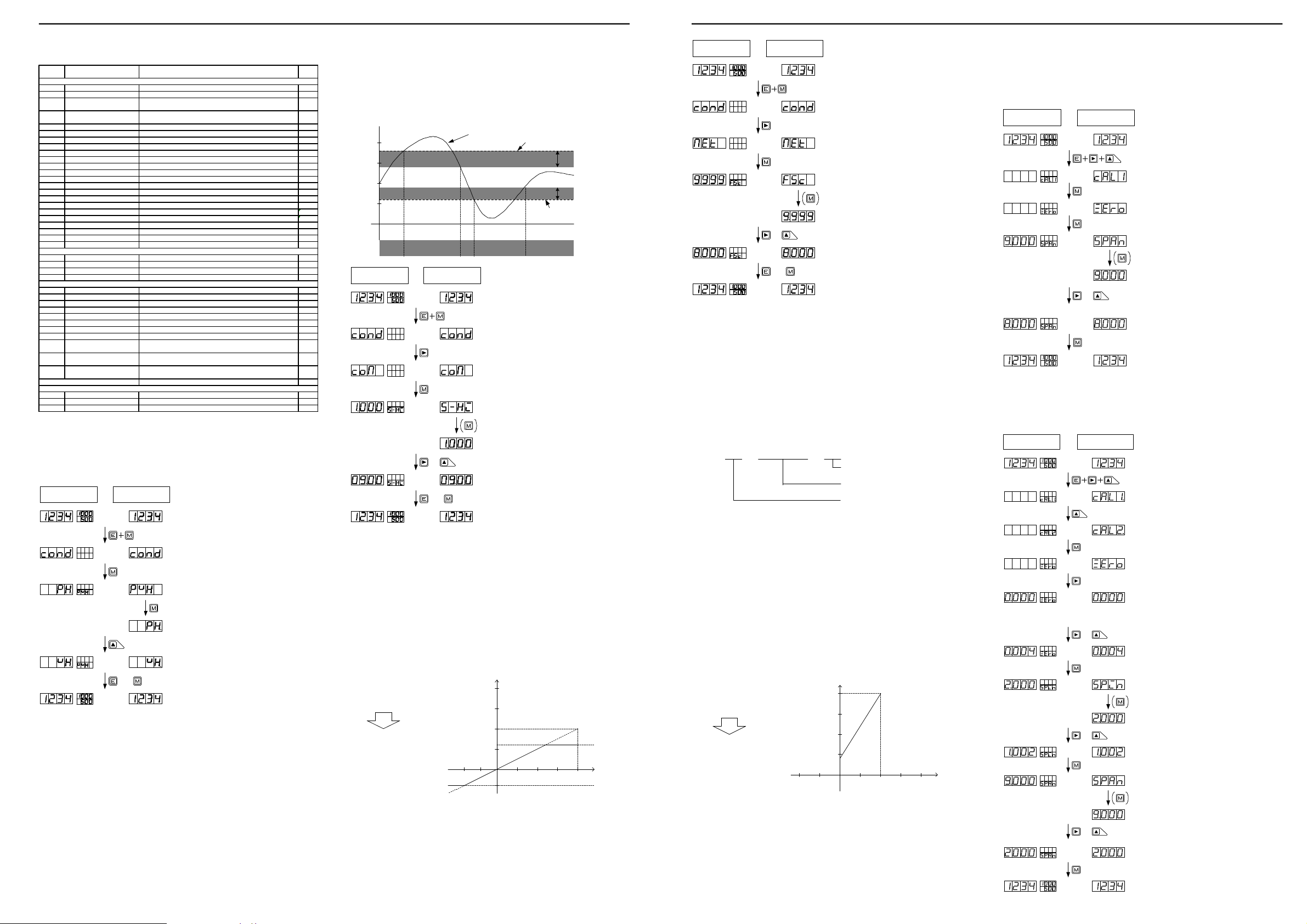
5.4.5 Method of Setting Linear izat ion Data
The linearization function means a function that changes the slope of straight lines in the
relationship between the input and indication by correcting the relations at arbitrary points.
Linearization data are set using the input value (indicated value before correction) and the
output value (indicated value after correction) at each arbitrary point.
Multi-display unit Single display unit
(1) Press the Mode key and the Enter key during
measurement.
(2) Press the Shift k ey a few times to move to the
linearization data menu.
(3) Press the Mode key to move to the setup for the
number of data to be c orrected.
(4) Press the Shift k ey (change digit) and the
&
&
&
&
Increment key (change numeric value) and then press
the Mode Key t o after the number of data to be
corrected has been set.
Note: The decimal point in the selec ted digit
flashes.
(5) For a single display unit, press the Mode key to
change to the parameter information indication.
Note: For a single display unit, the unit
automatically returns t o N-01 indication if there is
no key operation for about 8 seconds. In this case,
RE
press the Mode key to return to the numeric value
indication.
(6) Press the Shift k ey (change digit) and Increment
key (change numeric value) and then press the Mode
key after the N-01 input value has been set.
Note: For a single display unit, RE flashes when
DZ
the input value is s et and DZ flashes when the
output value is s et .
(7) Press the Shift k ey (change digit) and Increment
key (change numeric value) and then press the Mode
key after the N-01 output value has been set.
(8) Press the Mode key to display the set up for output
values of the data to be corrected.
Note: For a single display unit, t he unit is
automatically returned to N-02 indication if there is
no key operation for about 8 seconds. In this case,
RE
press the Mode key to return to the numeric value
indication.
(9) Press the Shift k ey (change digit) and Increment
key (change numeric value) and then press the Mode
key after the N-02 input value has been set.
Repeat steps (5) to (9) until all the s ettings have
been made.
(10) When all the settings have been made, press the
Enter key t o return to the meas urement mode.
Note: The setup conditions are N-1 < N-2 … N-15 < N-16.
6. Contr ol Functions
6.1 Hold Function
The Hold function temporarily retains the indication. The hold function is enabled by
shortcircuiting the HOLD and COM terminals or setting both terminals to the same
voltage level. As a result the display unit retains the indication given at that moment.
6.2 Digital Zero Fun ction
The Digital Zero function zeros the indication given at an arbitrary timing. Thereafter, the function shows the amount of change from the point of zeroing. However, this function serves as an indication resetting function for a frequency measuring unit. Thus, the Digital Zero function can be used to reset the indication
when there is no input signal at all.
Note that, the on/off control of the Digital Zero function can be achieved by means
of terminal control or front panel keys. In the case of terminal control, the Digital
Zero function is turned on by shortcircuiting the DZ and COM terminals or setting
both terminals to the same voltage level. The indication at that moment is zeroed.
In the case of control with the front panel keys, hold down the Mode key and press
the Increment key for about 1 second to zero the indication at that moment.
Note: Operation with the control terminals takes priority over operation
with the front panel keys. The Digital Zero function is disabled if the
control terminals are made to go through the off-on-off sequence with
the function enabled by means of the front panel keys.
6.3 Peak Hold Function
The Peak Hold function retains one of the maximum (peak hold)/minimum (valley
hold)/maximum - minimum (peak-valley hold) values and provides output for that
value. Selection from these values is made using the condition data. The peak
hold function is enabled by shortcircuiting the PH and COM terminals or setting
both terminals to the same voltage level.
7. Out put Function
7.1 Compar ison Output Function
The FD5000 series of unit meters is designed so that the two judgment values HI
and LO can be set for the measured (indicated) value to provide the results of
judgment as relay contact output. (This function is effective when the meter is
equipped with a comparison output unit.) For details on the contact ratings and
other specifications, refer to the section “Output Specifications.”
7.2 Analog Output Function
The FD5000 series of unit meters can output an analog signal for an indicated
value (when the meter is equipped with an analog output unit). There are four
output ranges, 0 to 1 V/0 to 10 V/1 to 5 V/4 to 20 mA, from which a selection
can be made using the condition data. In addition, the analog output of the
A5000 series allows for arbitrary output scaling. This scaling can be achieved
by setting the indication value for an output of the maximum scale value (20 mA
for 4–20 mA output range) in the AOHI parameter of the scaling data.
7.3 RS-485 I nterfa ce Function
The FD5000 series can be equipped with an RS-485 interface (when the meter is
provided with an RS-485 unit). For details on the RS-485 function, see the sepa-
rate manual on communication functions.
7.4 RS-232C Inter face Fun ction
The FD5000 series can be equipped with an RS-232C interface (when the meter
is provided with an RS-232C unit). For details on the RS-232C function, see the
separate manual on communication functions.
8. Specifications and External Dimensions
8.1 Input Specification s
8.1.1 DC Volta ge Measu ring Unit (range 11)
Measurement
Range
range
11 ±99.99mV
Input circuit : Single ended type
Operating system : ΔΣ conversion
Maximum sampling rate : 12.5 times per second
Noise rejection ratio : NMR (normal mode rejection) 50 dB or more (50 or 60 Hz)
Indication
Offset : ±9999
Full scale : 0 to ±9999
Highest
resolution
10μV
impedance
8.1.2 DC Volta ge Measu ring Unit (ranges 12 to 15)
Measurement
Range
range
12 ±999.9mV
13 ±9.999V 1mV
1415±99.99V
±600V
Input circuit : Single ended type
Operating system : ΔΣ conversion
Maximum sampling rate : 12.5 times per second
Noise rejection ratio : NMR (normal mode rejection) 50 dB or more (50 or 60 Hz)
Indication
Offset : ±9999
Full scale : 0 to ±9999
Highest
resolution
100μV
10mV
100mV
impedance
8.1.3 DC Cur rent Measur ing Unit
Measurement
Range
range
23 ±9.999mA 1μA
24
±999.9mA 100μA
25
Input circuit : Single ended type
Operating system : ΔΣ conversion
Maximum sampling rate : 12.5 times per second
Noise rejection ratio : NMR (normal mode rejection) 50 dB or more (50 or 60 Hz)
Indication
Offset : ±9999
Full scale : 0 to ±9999
Highest
resolution
10μA±99.99mA
impedance
Input
About
100MΩ
Input
About
100MΩ
About
1MΩ
About
10MΩ
About
10MΩ
Input
About
10Ω
About
1Ω
About
0.1Ω
Maximum
permissible
input
±100V ±(0.1% of FS)
Maximum
permissible
input
±100V
±250V
±250V
±600V
Maximum
permissible
input
±100mA
±500mA
±3A
Accuracy
Accuracy
±(0.1% of FS)
±(0.15% of FS)
Accuracy
±(0.2% of FS)
±(0.3% of FS)
5.2 Moving to t he Par ameter Setup M ode
Measurement
Shift data
Condition data Comparator data Scaling data Linearization data
Pressing the ENTER key saves the data and returns to the measurement mode.
(Data are backed up with EEPROM even when the power is turned off.)
Calibration data
5.3 Data Lists and Default Settings
Input u nit number Output unit number
Page 6
Instruction Manual for FD5000 Ser ies 7/12Instruction Manual for FD5000 Ser ies 6/12
Comparator data
Scaling data
Calibration data
Linearization data
and PPR=1 by default). Therefore, the parameters should be set as PS=2 and PPR=1 so that
5.4 Information on Each Parameter
Indication Name Setup options
Condition data
PVH Peak hold setup PH (peak hold)/VH (valley hold)/PVH (peak-valley hold) PH
RANG M eas urement range setup * 1 *1
Number of averaging operations
AVG
setup
Number of moving average
MAV
operations setup
S.UD Step width s etup 1(1digit)/2(2digit)/5(5digit)/0(10digit) 1
BLNK Indication blank setup OF F/B-3/B-2/B-1/ON OFF
UNIT Unit s etup C/F C
BAUD Baud rate set up 9600/4800/2400/384(38400)/192(19200) 9600
DATA Data length s etup 7(7bit)/8(8bit) 7bit
P.BIT Parity bit setup E (even number), O (odd number), N (none) E
S.BIT Stop bit setup 2(2bit)/1(1bit) 2
T- Delimiter s etup CR.LF(CR+LF)/CR CRLF
ADR Equipment ID setup 01 to 99 00
A.OUT Analog output setup OFF/ 0-1(0 to 1V)/0-10(0 to 10V)/1-5(1 to 5V)/4-20(4 to 20mA) OFF
B.UP Digital zero backup setup OFF/ON OFF
LINE Linearization setup OFF/ON CLR
I.SEL Input select ion OC (open collector)/LGC (logic)/MAG (magnet) O.C
TR T Tracking zeroing time s etup 00 to 99 00
TR V Tracking z eroing width setup *2 00 to 99 01
SNSR Sensor power setup 10(10V)/5(5V) 5
PONPower on delay time setup OFF/ ON OFF
PRO Protect setup OFF/1 t o 30 OFF
U-NO. Unit number indication setup OF F/ON ON
S-HI HI side judgment value setup -9999 to 9999 1000
S-LO LO side judgment value setup -9999 to 9999 500
H-HI HI side hysteresis setup 0 to 999 0
H-LO LO side hys teresis setup 0 to 999 0
FSC Full scale indic ation value setup -9999 to 9999 *1
FIN Full scale input value setup -9999 to 9999 *1
OFS Offset indication value setup -9999 to 9999 *1
OIN Offset input value setup -9999 to 9999 *1
PS Pre-scaling value setup 0.001 to 5.000 1.000
PPR Frequency division setup 1 to 100 1
DLHI Digital limiter HI value setup -9999 to 9999 9999
DLLO Digital li miter LO value setup -9999 to 9999 -9999
Analog output HI indication
AOHI
setup
Analog output LO indication
AOLO
setup
Decimal point indication positi on
DEP
setup
ZERO Zero input value -0.300 to 2.000 0.000
SPIN S pan input value 1.000 t o 3.000 2.000
SPAN S pan indication 0 to 9999 9000
1/2/4/8/10/20/40/80 1
OFF/2/4/8/16/32 OFF
-9999 to 9999 9999
-9999 to 9999 0
None/place of 100/place of 101/place of 102/place of 10
*2 *2
3
5.4.1M ethod of Setting Condition Data
This section shows a typical example of setting the peak hold parameter. The
same method applies to other parameters.
Multi-disp lay unit Si ngle dis play unit
(1) Press the Mode and Enter keys toge ther
during meas urement.
(2) Press the Mode key to change to the peak
hold s etup mode.
(3) For a sing le disp lay unit, pres s the Mode key
to change to the par ameter inform ation indicatio n.
(The dis play automatical ly change s to this
indic ation in about 1 s econd, except right after
COND is indicated.)
(4) Press the Increm ent key a few times to s et to
Valley Hold.
or
(5) Press the Enter key to return to meas ureme nt
mo de. (Pressi ng the Mode key change s to the
next paramete r).
Default
value
None
5.4.2 Method of Sett ing Compar ator Data
This section explains comparator data and shows a typical example of setting the
HI side judgment value. The same method applies to all other parameters.
HI side judgment value
HI side hysteresis value 200:
LO side judgment value
1000
900
500
300
0
Judgment
Multi-disp lay unit Si ngle dis play unit
: 900
: 300
150:LO side hyst eresis value
Indicated value
HIGO GO LO GO
&
or
HI side judgment value
LO side judgment value
(1) Press th e Mode and Enter keys together
during meas urement.
(2) Press th e Shift key a few times to disp lay the
comp arator data men u.
(3) Press th e Mode key a few times to disp lay th e
param eter to be se t.
(4) For a sing le disp lay unit, pres s the Mode key
to change to the par ameter inform ation indica tion.
(The dis play automatical ly changes to this
indic ation in about 1 s econd, except for parameter
S-HI right after COM is indi cated.)
(5) Press th e Shift key (change di git) and pres s
the Increme nt key (cha nge num eric va lue) to set
to 10.
Note:The decim al point in the se lected digit
flash es.
(6 ) P re ss th e E nte r ke y to re tur n t o t he
me asurem ent mode (Pres sing the Mode key
change s to the next param eter).
HI side hysteresis
200
range
LO side hyst eresis
150
range
Note: The setup conditions are HI side judgment value > LO side judgment
value, HI side judgment value LO side judgment value + LO side hys-
teresis, and LO side judgment value HI side judgment value-HI side
hysteresis. If these conditions are not satisfied, an error indication ap-
pears and the display returns to the HI side judgment value setup.
5.4.3 Method of Sett ing Scaling Data
This section explains comparator data and shows a typical example of setting the
full scale indication parameter. The same method applies to all other parameters.
Indication
Input volt age : 0 to 10V
0 to 5.000:Indication
Multi-display unit Single display unit
(1) Pr ess th e M ode and Ent er key s toge ther
during measurement.
(2) Press the Shift k ey a few times t o change to
the scaling data menu.
(3) Press the Mode key a few times to display the
parameter to be set.
(4) For a single display unit, press the M ode key
to change to the parameter information indication.
(The di spl ay aut oma tic all y c han ges to th is
indication in about 1 sec ond, except for parameter
FSC right after MET is indicated.)
(5) Press the Shift k ey (change digit) and press
&
or
the Increment key (change numeric value) to set
to 10.
Note:The decimal point in the selected digit
flashes.
( 6) P re s s t he E nt e r ke y t o r et ur n t o t he
me asur emen t mode (P ress ing th e M ode key
changes to the next parameter).
Note: For the process signal measuring unit, set the full scale input value to
5.000 for the 1 V range and to 20.00 for the 2 A range, and set the offset
input value to 1.000 for the 1 V range and to 4.00 for the 2 A range.
The following explains the frequency measuring unit. (The same method applies
to the full scale indication parameter.)
Determining the revolution speed (rpm) using the rotary encoder set to 30 pulses per minute:
(1)Determine the measurement range by calculating the maximum frequency.
The figure below shows an example where the revolution rises to a maximum speed of
about 100 rpm.
30 × 100 60
= 50
Number of pulses per second
Revolution speed per second
Number of pulses per revolution at the
rotary encoder
(2)Since the number of pulses determined in (1) is 50 per second (50 Hz), set the range to
range 11(for how to set the range, see the section on setting condition data).
(3)The display unit shows 500 if 50 Hz pulse input is measured under range 11 (when PS=1
the decimal point is positioned in the 101 digit(100.0 is is indicated 50 Hz input).
Note: For the frequency measuring unit, set the relationship between the input
and indication using the PS and PPR parameters (parameters of FSC,
FIN, OFS, and OIN are not indicated).
The following explains the scaling of analog output (The same method applies to
the full scale indication parameter.)
Output
Indication
Output
:
0.0 to 500.0
4 to 20mA
:
20mA
5.4.4 Method of Setting Calibra tion Dat a
5.4.4.1 Actual Loa d Ca libr at ion
Actual load calibration means that calibration is carried out by applying actually
measured pressure to a sensor such as a load cell connected to the meter.
Multi-display unit Single display unit
(1) Pr ess the Shift, Inc reme nt, and Enter keys
together during measurement.
(2) Press the M ode key t o ch ange to t he a ctual
load calibration mode.
(3) Press the M ode ke y whi le ap plying pressure
that will cause the display to show zero.
Err1: When the input at the time of zero calibration
is below -0.3mV/V, it displays.
Err2:
When the input at the time of zero calibration is
more than 1mV/V, it displays.
(4) For a s ingle display unit, press the Mode key to
change to the parameter information indication.
(5 ) Pr es s the S hi ft k ey (c ha ng e dig it ) and
Increment key (change numeric value) to set 8000.
&
No te:T he deci mal poi nt in the sel ecte d d igit
flashes.
Err3: It is the same as that of the time of being an
input at the time of span calibration at the zer o
proofreading time, or when small, it displays.
Err4:
When the input at the time of span calibration is
more than 3.3mV/V, it displays.
Err5:
When the setup more than the highest
decomposition ability is performed, it displays.
( 6) Pr es s th e M od e ke y t o re tu rn to th e
measurement mode.
5.4.4.2 Equ ivalent Calibration
Equivalent calibration means that calibration is carried out according to the rat-
ings (specifications) of such a sensor as a load cell. It is not necessary to connect
the sensor or to apply pressure to the sensor.
Mult i-displa y unit Sing le displ ay unit
(1) P ress the Shift, In cremen t, and En ter key t ogether
durin g meas urement .
(2) P ress the Increm ent key to select the equi valent
calib ration m ode.
(3) P ress the Mode k ey to mo ve to the equiva lent
calib ration m ode.
(4) P ress the Shift ke y to disp lay the z ero-inpu t setup
mod e.
Note :For a s ingle dis play unit , the uni t
auto matically returns to ZERO indicat ion if the re is
no k ey oper ation for about 8 second s. In suc h a
cas e, press the Mod e key to return to the
num erical va lue indic ation.
(5) P ress the Shift ke y (chang e digit) and the
&
Incre ment ke y (chan ge nume ric valu e) to set 0.004.
Note :The de cimal po int in the selecte d digit fla shes.
(6) P ress the Mode k ey to ch ange to the span input
valu e setup mode.
Err1:
Whe n the inp ut at the time of zero cali bration
is be low -0.3m V/V, it d isplays .
Err2: When the inp ut at t he time of zero calibra tion is
more than 1m V/V, it d isplays .
(7) F or a sing le displ ay unit, p ress the mode k ey to
disp lay the p aramete r inform ation ind ication.
5000
F S C : 5000
F I N : 9999
O F S : 0
O I N : 0
DLH I : 3000
DLLO : -2000
D E P : The place of 103 is li t.
0
-2000
10V
DLHI3000
Input
DLLO
Note: For the Digital limiter, values larger than the DLHI setpoint are not indi-
cated even if signals greater that the value set in the DLHI parameter are
input (for DLLO parameter, values smaller than the DLLO setpoint are
not indicated).
AOHI : 5000
AOLO : 0
4mA
5000
0
Indication
Note 1: For analog output scaling, set the indication value for an output current
of 20 mA in the AOHI parameter and set the indication value for an
output current of 4 mA in the AOLO parameter (for 4-20 mA output).
Note 2: The analog signal out of the setting range cannot be accurately output.
&
&
(8) P ress the Shift ke y (chang e digit) and the
Incre ment ke y (chan ge nume ric valu e) to set 1.002.
(9) P ress the Mode k ey to ch ange to the span
indic ating va lue setu p mode.
(10) For a sin gle disp lay unit, press th e Mode key to
disp lay the p aramete r inform ation ind ication.
(11) Press th e Shift k ey (chan ge digit ) and the
Incre ment ke y (chan ge nume ric valu e) to set 2000.
Note :The de cimal po int in the selecte d digit
flash es.
Err3: It is the sam e as tha t of the time of being an
input at the t ime of s pan cal ibration at the zero
proofr eading ti me, or w hen sma ll, it dis plays.
Err4:
When the inpu t at the time of span ca libration is
more than 3 .3mV/V , it disp lays.
Err5:
When the set up more than t he high est
deco mpositio n ability is perfo rmed, it displays .
(12) Press th e Mode key to re turn to t he meas uremen t
mod e.
 Loading...