

Page 1
*8195794*
H14/H17/H22 SERIES
ELECTRIC FRYERS
Service & Parts Manual
Beginning with Series Code AN
Frymaster, a member of the Commercial Food Equipment Service Association, recommends
using CFESA Certified Technicians.
24-Hour Service Hotline 1-800-551-8633
AUG 2005
Page 2
NOTICE
IF, DURING THE WARRANTY PERIOD, THE CUSTOMER USES A PART FOR THIS
ENODIS EQUIPMENT OTHER THAN AN UNMODIFIED NEW OR RECYCLED PART
PURCHASED DIRECTLY FROM FRYMASTER/DEAN, OR ANY OF ITS AUTHORIZED
SERVICE CENTERS, AND/OR THE PART BEING USED IS MODIFIED FROM ITS
ORIGINAL CONFIGURATION, THIS WARRANTY WILL BE VOID. FURTHER,
FRYMASTER/DEAN AND ITS AFFILIATES WILL NOT BE LIABLE FOR ANY
CLAIMS, DAMAGES OR EXPENSES INCURRED BY THE CUSTOMER WHICH
ARISE DIRECTLY OR INDIRECTLY, IN WHOLE OR IN PART, DUE TO THE
INSTALLATION OF ANY MODIFIED PART AND/OR PART RECEIVED FROM AN
UNAUTHORIZED SERVICE CENTER.
DANGER
Copper wire suitable for at least 167°F (75°C) MUST be used for power
connections.
DANGER
The electrical power supply for this appliance MUST be the same as
indicated on the rating and serial number plate located on the inside of the
fryer door.
DANGER
This appliance MUST be connected to the voltage and phase as specified
on the rating and serial number plate located on the inside of the fryer
door.
DANGER
All wiring connections for this appliance MUST be made in accordance
with the wiring diagrams furnished with the equipment. Wiring diagrams
are located on the inside of the fryer door.
DANGER
Do not store or use gasoline or other flammable vapors and liquids in the
vicinity of this or any other appliance.
WARNING
Do not attach accessories to this fryer unless fryer is secured from tipping.
Personal injury may result.
WARNING
Frymaster fryers equipped with legs are for permanent installations. Fryers
fitted with legs must be lifted during movement to avoid damage and
possible bodily injury. For a moveable or portable installation, Frymaster
optional equipment casters must be used.
Questions? Call 1-800-551-8633
Page 3
WARNING
Do not use water jets to clean this equipment.
DANGER
All wiring connections for this appliance MUST be made in accordance
with the wiring diagrams furnished with the equipment. Wiring diagrams
are located on the inside of the fryer door.
WARNING
This equipment is intended for indoor use only. Do not install or operate
this equipment in outdoor areas.
Electrical Requirements
MODEL VOLTAGE PHASE WIRE
SERVICE
H14 208 3 3 6 (16) 39 39 39
H14 240 3 3 6 (16) 34 34 34
H14 480 3 3 8 (10) 17 17 17
H14 220/380 3 4 6 (16) 21 21 21
H14 240/415 3 4 6 (16) 20 20 21
H14 230/400 3 4 6 (16) 21 21 21
ALL
EPH14
SERIES
(SOLID STATE)
H17 208 3 3 6 (16) 48 48 48
H17 240 3 3 6 (16) 41 41 41
H17 480 3 3 6 (16) 21 21 21
H17 220/380 3 4 6 (16) 26 26 26
H17 240/415 3 4 6 (16) 24 24 24
` 230/400 3 4 6 (16) 25 25 25
ALL 208 3 3 6 (16) 48 48 48
EPH17
SERIES
(SOLID STATE)
H22 208 3 3 4 (25) 61 61 61
H22 240 3 3 4 (25) 53 53 53
H22 480 3 3 6 (16) 27 27 27
H22 220/380 3 4 6 (16) 34 34 34
H22 240/415 3 4 6 (16) 31 31 31
H22 230/400 3 4 6 (16) 32 32 32
208 3 3 6 (16) 39 39 39
240 3 3 6 (16) 34 34 34
220/380 3 4 6 (16) 21 21 21
240/415 3 4 6 (16) 20 20 20
240 3 3 6 (16) 41 41 41
220/380 3 4 6 (16) 26 26 26
240/415 3 4 6 (16) 24 24 24
MIN.
SIZE
AWG
(mm2)
AMPS PER LEG
L1 L2 L3
Page 4

TABLE OF CONTENTS
Page #
CHAPTER 1 – SERVICE PROCEDURES
1.1 General
1.2 Replace Computer Controller 1-1
1.3 Replace Interface Board 1-2
1.4 Replace Transformer 1-3
1.5 Replace Temperature Probe 1-3
1.6 Replace Heating Element 1-6
1.7 Replace High-Limit 1-9
1.8 Replace Frypot 1-10
1.9 Replace Contactor 1-10
1.10 Built-in Filter System Service Procedures 1-12
1.11 Basket Lift Service Procedures 1-17
1.12 Electric Interface Board Diagnostic Chart 1-20
1.13 Simplified Wiring Diagrams, Common Electric 1-21
1.14 Wiring Diagrams, Main 1-26
1.15 Wiring Diagrams, Basket Lifts 1-32
1.16 Wiring Diagrams, Filtration Systems 1-34
CHAPTER 2 – PARTS LIST 2-1
2.1 Accessories 2-1
2.2 Basket Lift Assemblies and Component Parts 2-2
2.3 Cabinet Assemblies and Component Parts 2-4
2.4 Casters, Legs and Associated Hardware 2-12
2.5 Component Box Assemblies and Associated Hardware
2.6 Control Panels Assemblies, Doors, and Related Components
2.7 Controller Assemblies
2.8 Electrical Components 2-18
2.9 Filter Base/Pan Assemblies
2.10 Filter Pump and Motor Assemblies and Associated Hardware 2-33
2.11 Drain System Components
2.12 Filtration System Components 2-39
2.13 Frypot Assemblies and Drain Valve Components 2-42
2.14 High-Limit Thermostat and Related Components
1-1
1-1
2-14
2-15
2-17
2-25
2-38
2-44
i
Page 5
H14/H17/H22 SERIES ELECTRIC FRYERS
CHAPTER 1: SERVICE PROCEDURES
1.1 General
Before performing any maintenance on your Frymaster fryer, you must disconnect the electrical
power supply.
When electrical wires are disconnected, it is recommended that they be marked in such a way as to
facilitate re-assembly.
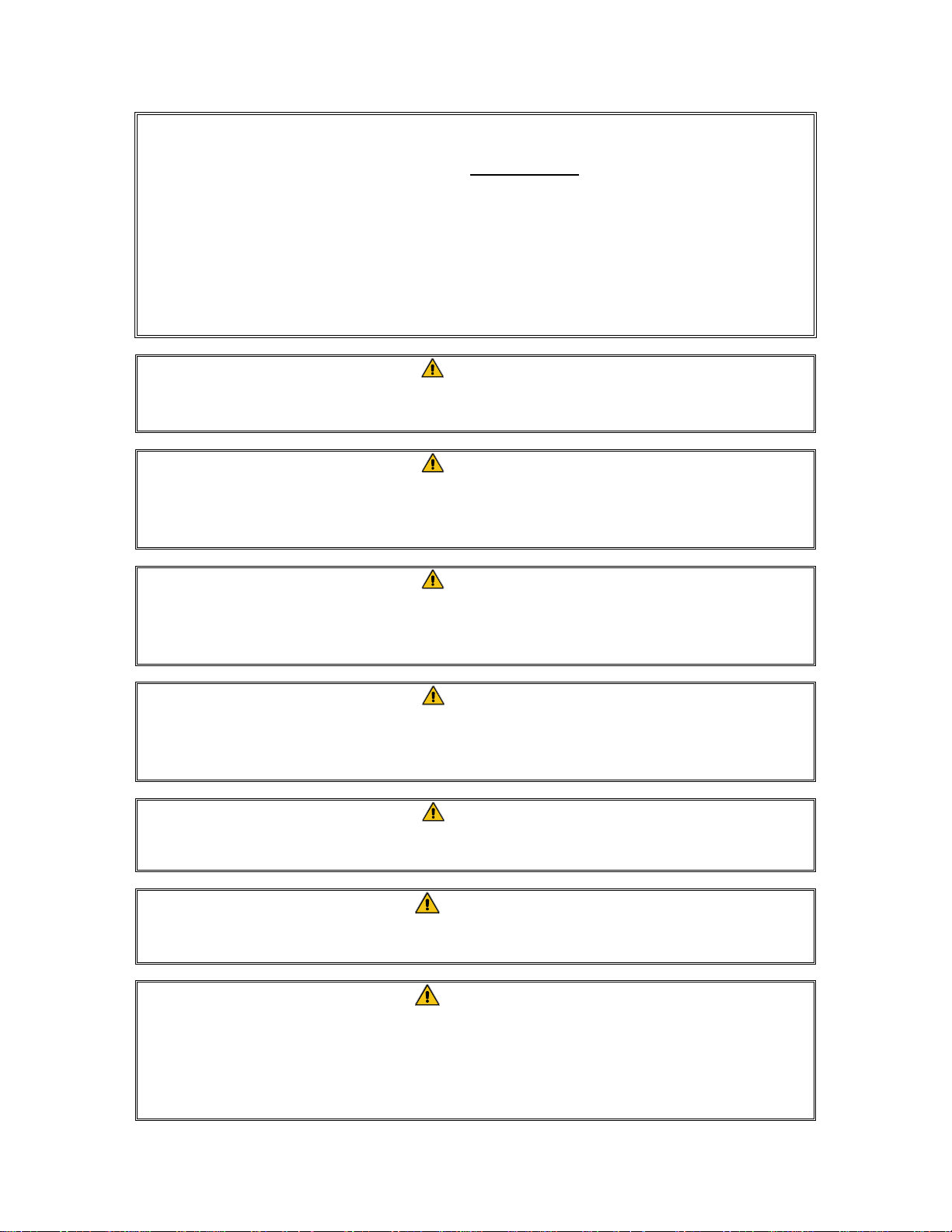
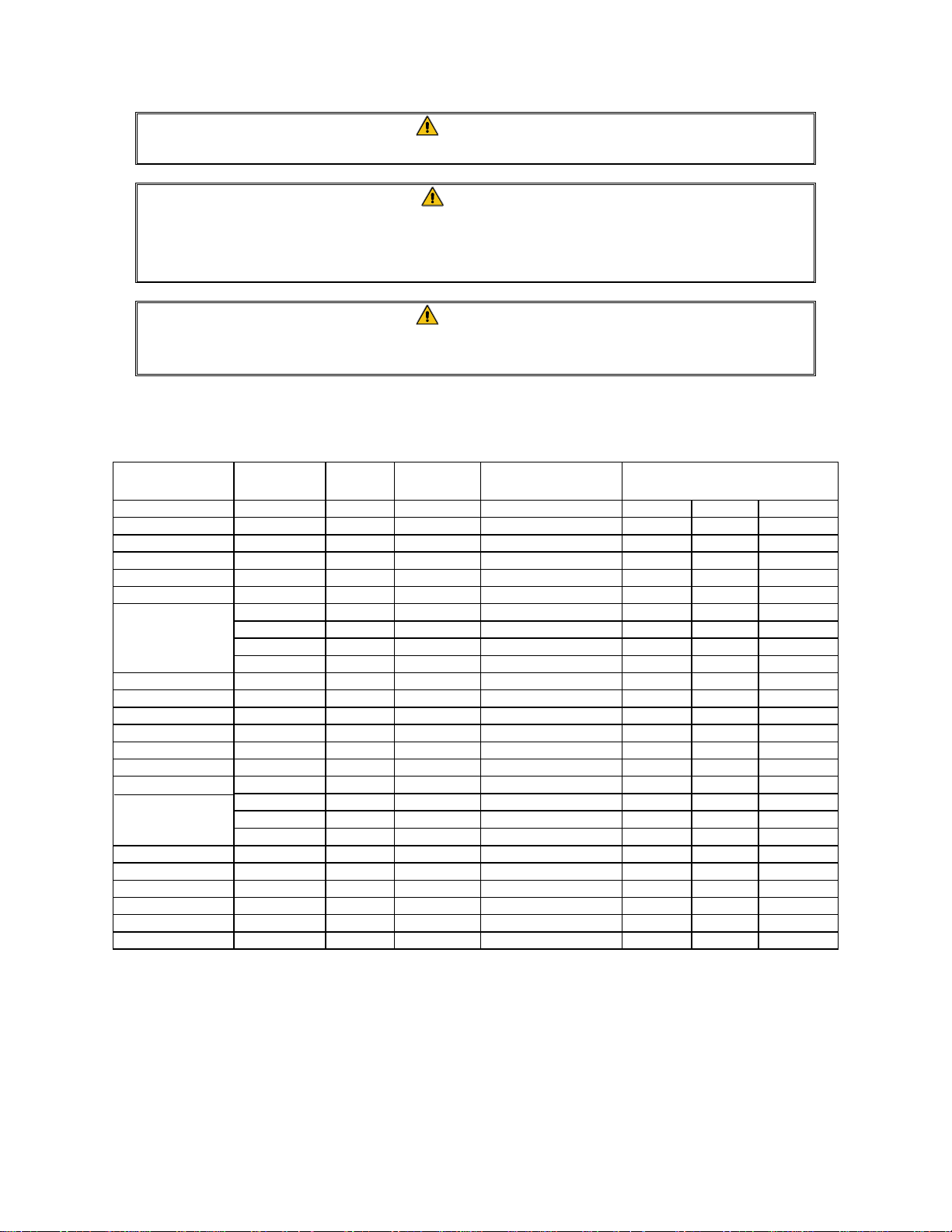
1.2 Replace Computer/Controller
1. Unscrew and remove two control panel
screws.
2. Control panel is hinged at the bottom and will
swing open from the top.
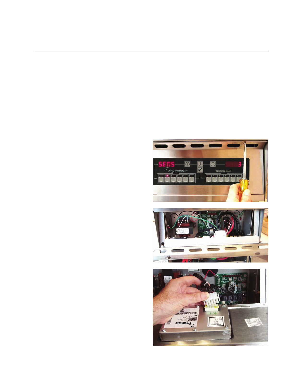
3. Unplug wiring harness at plug on back of
controller.
4. Control panel including controller can be
removed by lifting the assembly from the
hinged slots in the control panel frame.
5. Reverse procedures to install new controller.
1-1
Page 6
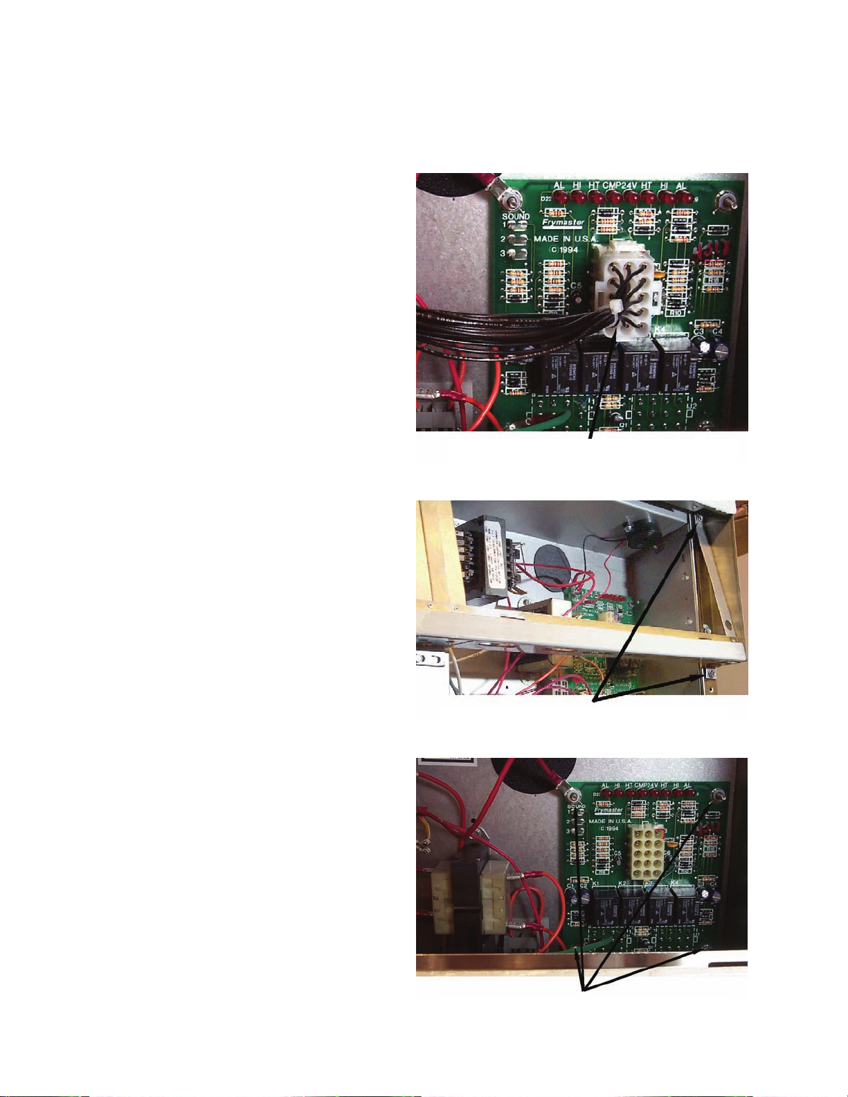
1.3 Replace Interface Board
1. Unplug all power cords. Perform Procedure 1.2, Steps 1-4, Replace Computer/Controller.
2. Unplug wire harness from the interface
board. Remove all wiring from the terminals
of the interface board, ensuring that each wire
is marked for reattachment.
3. Remove the screws securing the control panel
frame. Set the control panel frame/screws
aside.
4. Remove the screws securing the top cap. Set
the top cap/screws aside.
5. Remove the screws securing the component
box. Set the component box drop down
enough so that the wire harness can be
unplugged from the back of the assembly.
6. Remove the nuts from each corner of the
interface board and slide the board from the
studs. Ensure that standoffs remain in place
on studs, prior to installing new interface
board. Install the new interface board by
reversing the previous procedures. Ensure
that wire harnesses are connected to back of
interface board prior to securing component
box. Also ensure that wiring and wire
harnesses are connected to the proper
terminals.
Screws securing control panel frame
Wire harness/connector
Nuts securing interface board
1-2
Page 7
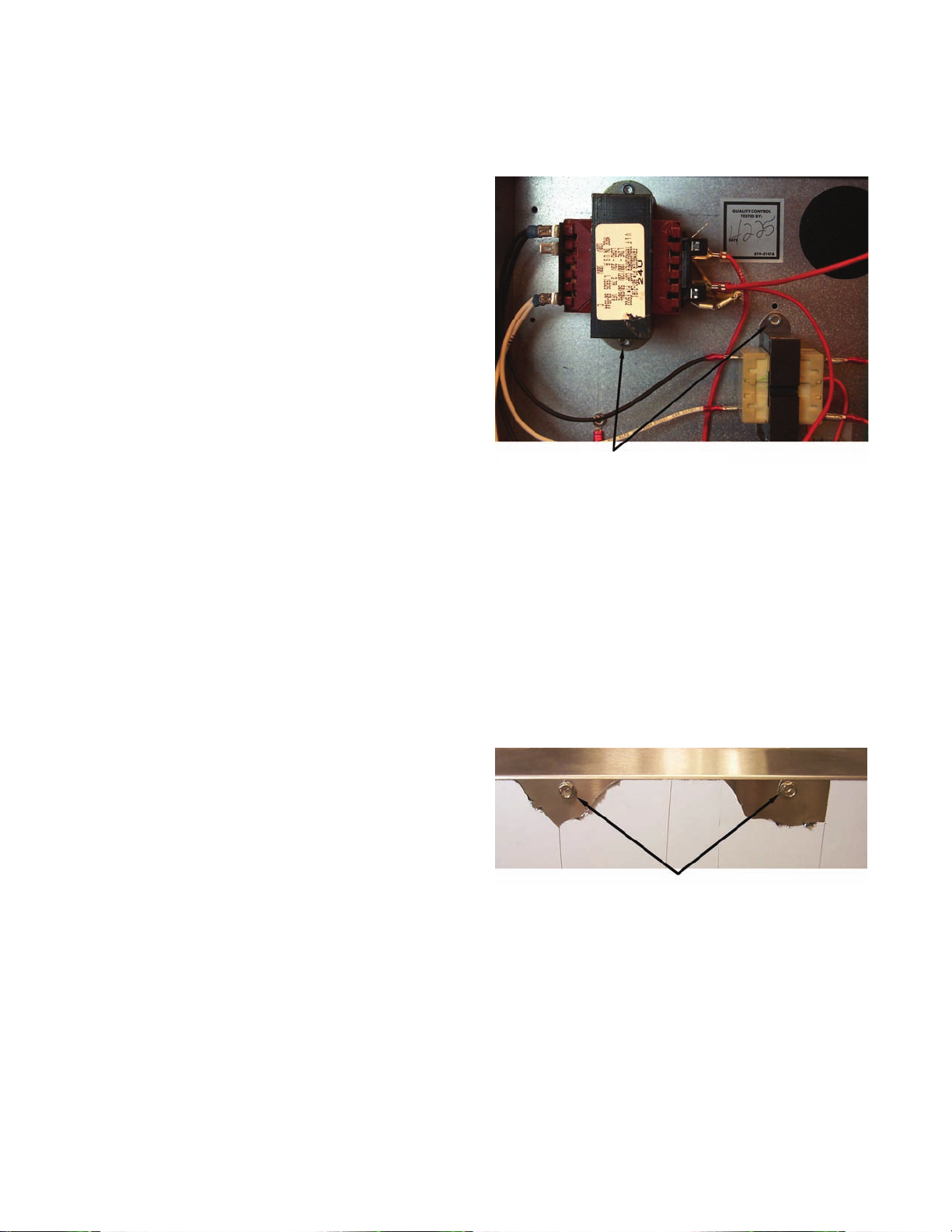
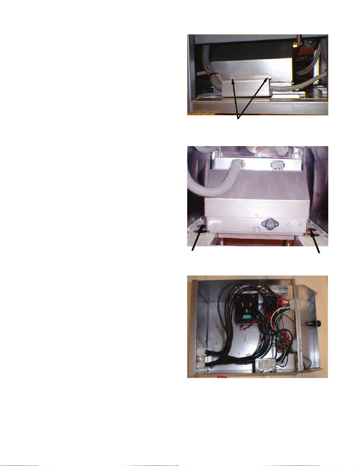
1.4 Replace Transformer
1. Unplug all power cords. Perform Procedure 1.2, Steps 1-4, Replace Computer/Controller.
2. Remove all wiring from the terminals of the
transformer to be replaced.
3. Remove the screws that secure the
transformer to the component box.
4. Install the new transformer by reversing the
preceding procedures. Make sure you
reconnect the wiring to the proper terminals
and the harnesses to the correct connectors.
Screws securing transformers
1.5 Replace Temperature Probe
1. Unplug fryer from the electrical source.
2. Drain the cooking oil from the frypot.
3. Remove the fryer from the exhaust hood to gain access to the rear of the fryer.
4. Remove the screws from the top, center and
bottom back covers. Set the covers and
screws aside.
5. Remove the screws securing the tilt housing
cover. Set the tilt housing cover aside.
Screws securing back covers and tilt housing
1-3
Page 8
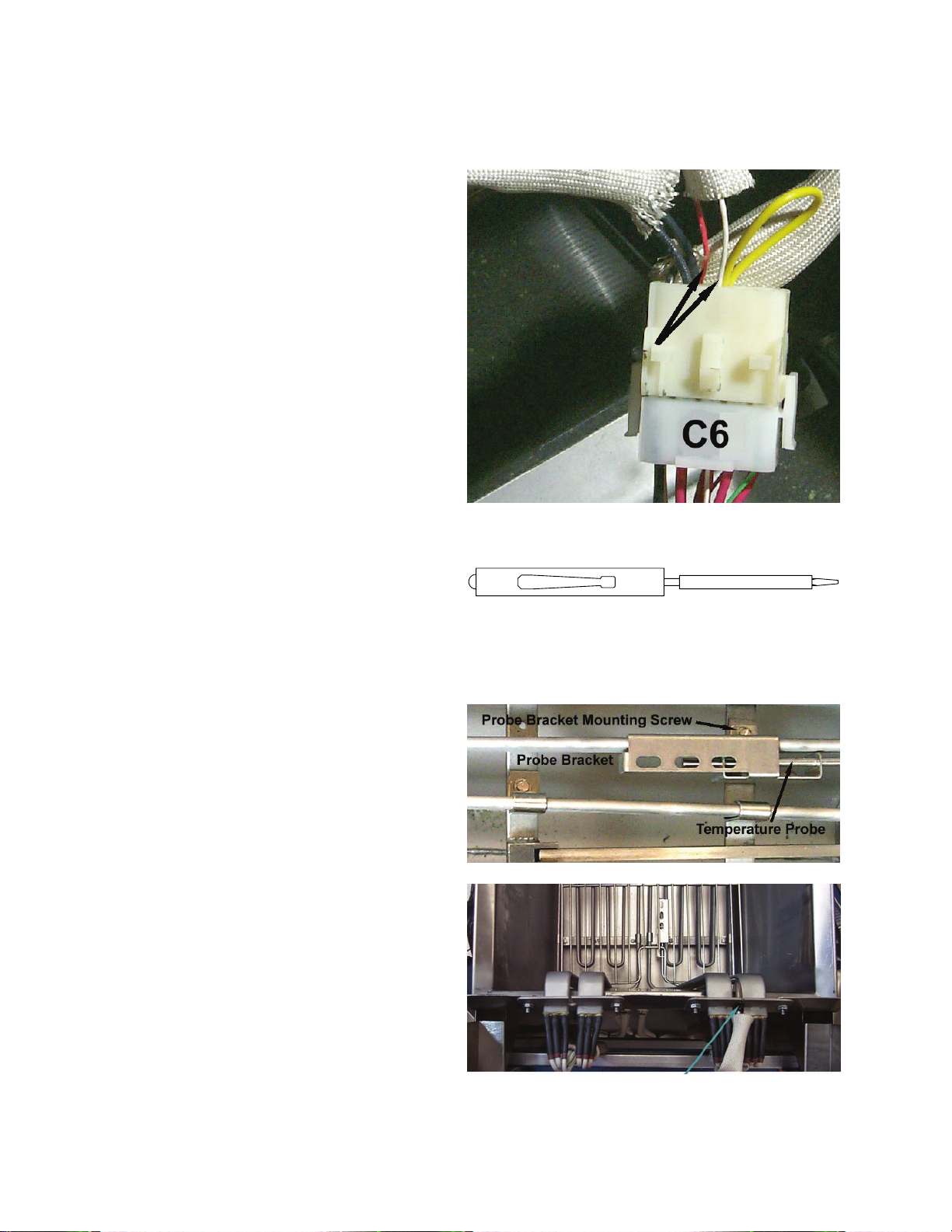
6. Disconnect the wire harness containing the
probe wiring. It may be necessary to remove
the wire ties.
7. Use a pin-pusher (P/N 806-4855 or P/N 807-
0928—see Section 1.7) to remove the probe
wires from the connector. Mark each wire
for re-assembly.
8. Remove the screw(s) securing the probe
bracket to the element.
9. Thread the probe wire through the hole in the
tilt plate assembly and remove the probe and
the securing components from the element.
10. Remove the probe from the probe bracket.
Place the new probe into the bracket.
Use a pin-pusher to remove probe wires from
connector
Pin-pusher (Frymaster P/N 806-4855)
Thread probe wire through hole in tilt plate assembly,
then remove probe and components from element.
1-4
Page 9
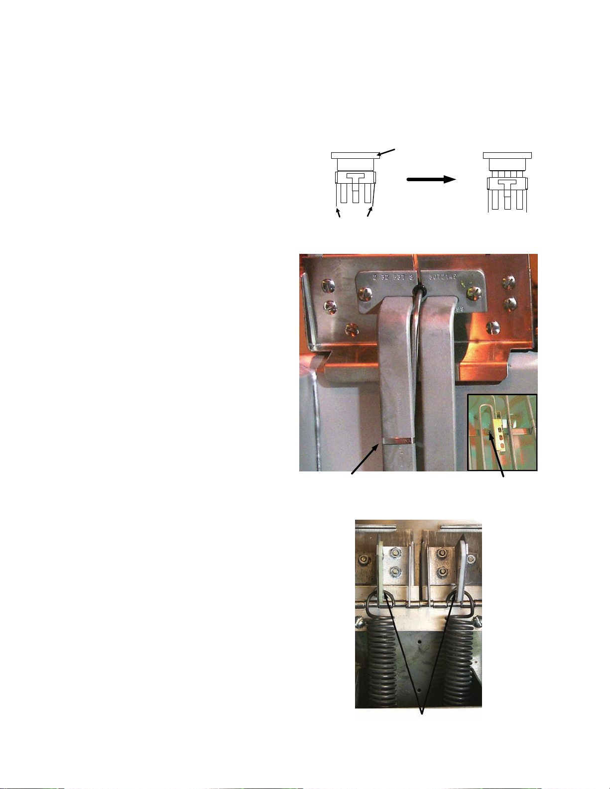
11. Place the new temperature probe assembly
onto the element and secure with the screws
removed earlier. Clip the probe onto the rear
of the element. The temperature probe
assembly should be oriented in the same
manner as the probe being replaced.
12. Thread the probe wires into the harness
connector as removed in Step 7.
13. Lower the element into the frypot.
14. Place the tilt housing cover over the tilt
housing assembly and secure with screws
15. Install the top, center and bottom back covers
and secure with screws.
Secure probe to
element with metal
wire-wrap
Tilt housing cover in place
New probe assembly
properly installed in
tilt plate
1-5
Page 10
1.6 Replace Heating Element
1. Perform Procedure 1.5, Replace Temperature Probe, Steps 1-7.
2. Remove the element wires from the
connector. Press down on either side of the
connector while pulling up on the top portion.
The connector will open from the top. Pull
all wires from the connector.
3. Remove the screws securing the temperature
probe bracket from the element. Remove the
probe clamp (metal wire-wrap). Set the
temperature probe and probe-securing
components aside.
4. Disconnect the element springs.
Push in on tabs to release
Remove probe clamp (metal wire-wrap), and screws
securing probe bracket to element.
Harness
Connector
Closed
top portion
Harness
Connector
Open
Top Portion
1-6
Disconnect element springs here
Page 11
5. Remove the element mounting-screws and
pull the element out of the frypot (split-vats).
On full-vat elements, remove the element
clamps and hardware before removing
mounting-screws and nuts on the defective
element.
6. Install the replacement element in the frypot
and secure with the mounting screws
removed in Step 5.
7. Re-install the temperature probe and probe-
securing components onto the replacement
element.
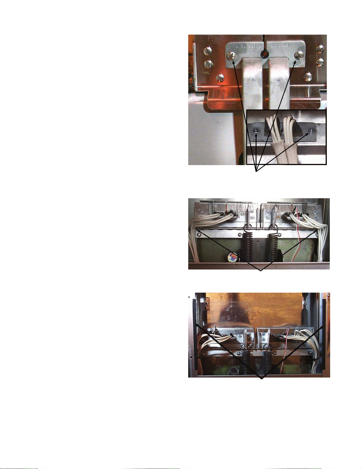
8. Route the element leads (terminals) to the
rear of the fryer. Ensure that chafing guards
are in place to prevent wire chafing while
raising and lowering elements.
Front
Back
Element mounting-screws and nuts. (Inset Photoback of tilt plate)
Proper element-wire routing is essential to prevent
wire chafing while raising and lowering elements.
Chafing guards on cabinet edges also help prevent
wire chafing while raising and lowering elements.
1-7
Page 12
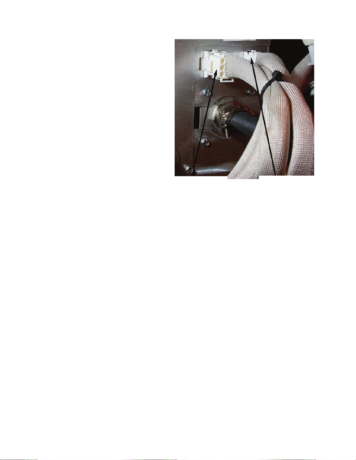
9. When replacing the right element (as viewed
from the rear of the fryer), insert pin
terminals into the corresponding pin-holes in
the 6-pin connector. When all pin terminals
have been fully inserted, close the connector
by sliding the halves together until the tabs
snap back into place (reverse procedure in
Step 2).
10. When replacing the left element (as viewed
from the rear of the fryer), use the 9-pin
connector, inserting the leads from the
replacement element and closing the
connector, see previous step.
11. Insert the connector(s) into the receptacle(s)
on the rear of the contactor box, ensuring that
the latches lock the connectors in place (see
Step 9).
12. Install the temperature probe wires (marked
for re-assembly) in the corresponding pin
locations.
13. Reconnect the element spring.
14. Place the tilt housing cover over the tilt
housing assembly and secure with screws.
15. Install covers and secure with screws.
16. Position fryer under exhaust hood.
Left Element—
9-Pin Connector
Right Element—
6-Pin Connector
1-8
Page 13
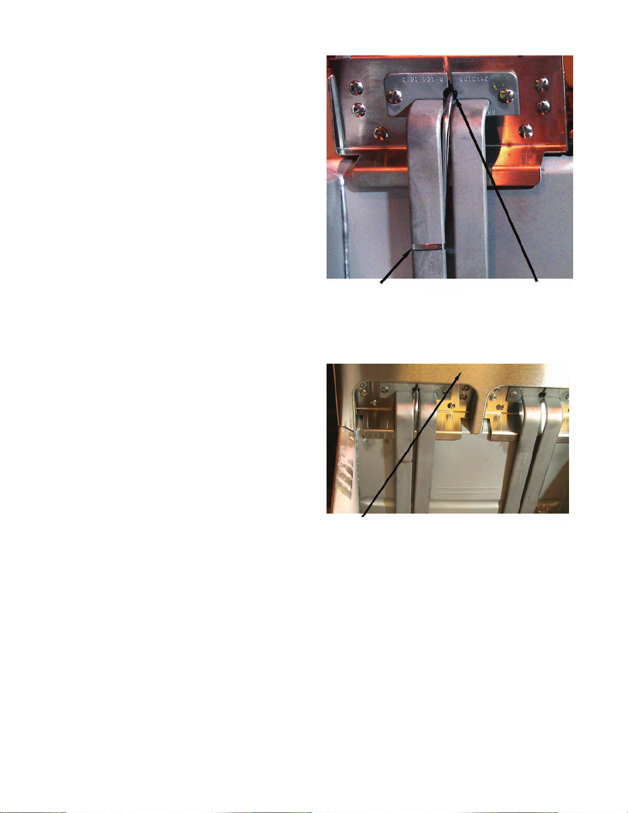
1.7 Replace High-Limit
1. Perform Procedure 1.5, Replace Temperature
Probe, Steps 1-4.
2. Disconnect the wire harness containing the
high-limit wires.
3. Use a pin-pusher (P/N 806-4855 or P/N 807-
0928) to remove the two high-limit wires
from the wire harness connector. For splitpot fryers, remove only the wires for the
high-limit to be replaced. Mark each wire for
re-assembly.
4. Remove the high-limit from the frypot using
an open-end wrench or other suitable tool.
5. Apply Loc-Tite PST 567 sealant to the
replacement high-limit threads.
6. Screw the replacement high-limit into the
frypot and tighten securely. DO NOT
OVERTIGHTEN.
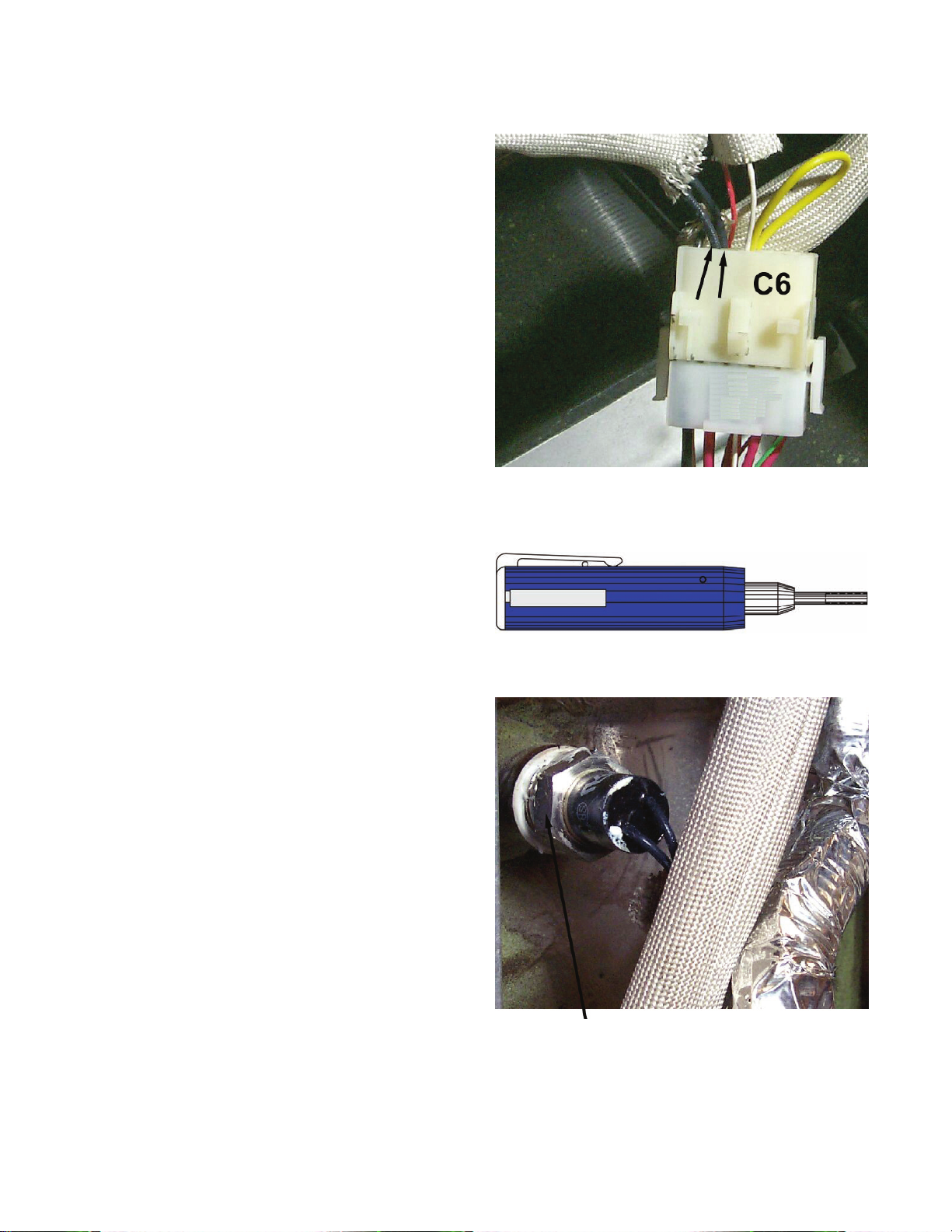
7. Insert the replacement high-limit wires into
the proper pin-holes in the connector. The
same two pin-holes from which the defective
high-limit wires were removed.
8. Reconnect the wire harness connector.
9. Install and secure the back covers.
10. Position the fryer under the exhaust hood.
Proper element-wire routing is essential to prevent
wire chafing while raising and lowering elements.
Pin Pusher— P/N 807-0928
Place wrench here when removing and installing
high-limit.
1-9
Page 14

1.8 Replace Frypot
1. Perform Procedure 1.5, Replace Temperature Probe, Steps 1-7.
2. Perform Procedure 1.2, Replace Computer/Controller, Steps 1-6.
3. Disconnect the wire harness containing the high-limit wires.
4. Use a pin-pusher to remove the high-limit wires from the wire harness connector.
5. Remove the high-limit from the frypot.
6. Disconnect the wire-harnesses connected to the contactor box.
7. Remove the screws securing the capping piece from the fryer. Remove the capping piece and set
aside. It may be necessary to remove the wiring covers from the front of the contactor box.
8. If the fryer has a built-in filtration system, remove all the plumbing from the frypot, including
rear-flush and square-drain plumbing.
9. Remove the screws securing the frypot to the front frame of the fryer.
10. Carefully lift the frypot from the cabinet.
11. Remove the drain valve from the old frypot and install on the new frypot.
12. Apply Loc-Tite Sealant PST 567 to the high-limit threads. Install the high-limit into the new
frypot.
13. Disconnect the tilt plate springs from the old frypot.
14. Remove the securing screws from the tilt plate. Lift the tilt plate/heating element assembly from
the old frypot and install on the new frypot.
15. Follow the preceding steps in reverse to install the new frypot into the fryer.
16. NOTE: Apply Loc-Tite Sealant PST 567 to all pipefittings prior to installation.
1.9 Replace Contactor
1. Perform Procedure 1.4, Replace Temperature Probe, Steps 1-3.
2. Remove the screws securing the bottom and center rear access covers. Set the screws and covers
aside.
1-10
Page 15
3. If present, remove the screws securing the
wiring covers to the front of the contactor box
(optional on old-style contactor boxes). Set
the screws and covers aside.
4. Disconnect the wire harnesses from the front
and rear of the contactor box.
5. Remove the screws securing the contactor
box to the bottom frame of the fryer.
6. Pull the contactor box through the access
opening in the rear of the fryer.
7. Remove the screws securing the contactor
box cover. Set the screws and covers aside.
8. Remove all wiring connected to the contactor
terminals inside the contactor box. Mark
each wire for re-assembly.
Screws securing wire cover to contactor box
(optional on old-style contactor boxes)
Screw location securing contactor box to bottom
frame
Mark each wire for re-assembly, then remove all
wiring connected to the contactor(s) to be replaced.
1-11
Page 16
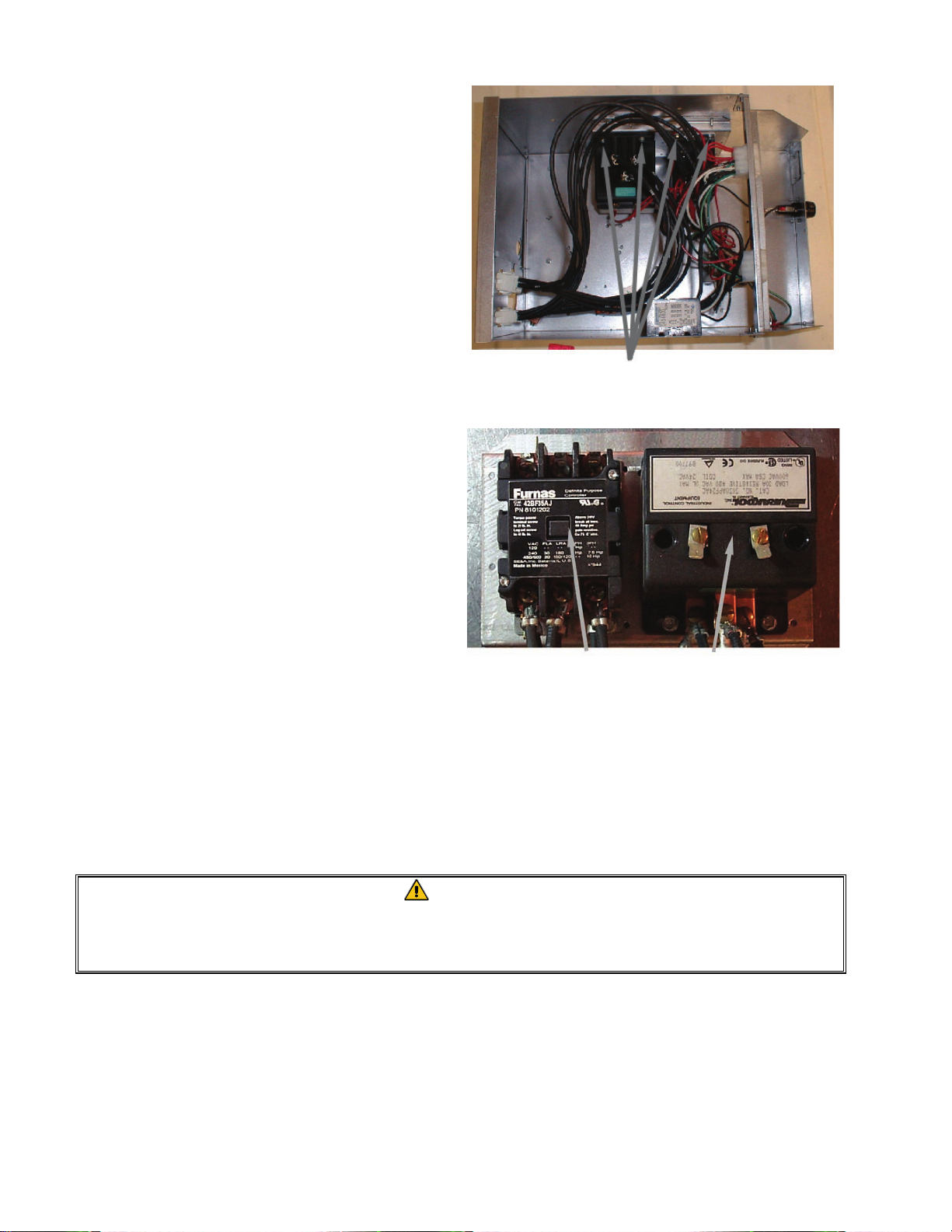
9. Remove the contactor mounting screws and
remove the contactor.
10. Install the new contactor and connect the
wiring removed in Step 8.
11. Install the contactor box by following the
previous steps in reverse order.
Contactor mounting screws
Latching Contactor
Mercury Contactor
1.10 Built-in Filter System Service Procedures
Filtration Problem Resolution
One of the most common errors is placing the filter paper on the bottom of the filter pan rather than
over the filter screen.
CAUTION
Ensure that filter screen is in place prior to filter paper placement and filter pump
operation. Improper screen placement is the major cause of filter system
malfunction.
Whenever the complaint is “the pump is running, but no oil is being filtered,” check the installation
of the filter paper, and ensure that the correct size is being used. While you are checking the filter
paper, verify that the O-ring on the bottom of the filter pan is present and in good condition. A
missing or worn O-ring allows the pump to take in air and decreases its efficiency. Also, oil leaks
on the floor each time a vat is drained.
1-12
Page 17
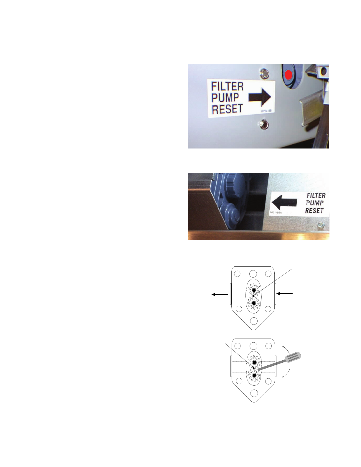
If the pump motor overheats, the thermal overload will trip and the motor will not start until it is
reset. If the pump motor does not start, press the red reset switch (button) located on the rear of the
motor.
If the pump starts after resetting the thermal
overload switch, then something is causing the
motor to overheat. A major cause of overheating
is when several frypots are filtered sequentially,
thus overheating the pump and motor. Allow the
pump motor to cool at least 30 minutes before
resuming operation.
Pump overheating can be caused by:
• Solidified shortening in the pan or filter
lines,
or
• Attempting to filter unheated oil or
shortening.
Cold oil and shortening are more viscous,
causing the pump motor to load up and overheat.
If the motor runs but the pump does not, there is
a blockage in the pump. Incorrectly sized or
installed paper/pads will allow food particles and
sediment to pass through the filter pan and into
the pump. When sediment enters the pump, the
gears bind, causing the motor to overload, again
tripping the thermal overload. Shortening that
has solidified in the pump will also cause it to
seize, with the same result.
A pump seized by debris or hard shortening can
usually be freed by manually moving the gears
with a screwdriver or other instrument.
Disconnect power to the filter system.
Remove the input plumbing from the pump.
Reset switch location: Old-style FPIII
Reset switch location: New-style FPIII
Sediment Particle
Sediment Particle
Oil Flow
Up for reverse
Down for forward
1-13
Freeing a seized pump.
Page 18

Use a screwdriver to manually turn the gears, in which:
● Turning the pump gears in reverse will release a hard particle.
● Turning the pump gears forward will push softer objects and solid shortening through the
pump and allow free movement of the gears.
Incorrectly sized or installed paper/pads will also allow food particles and sediment to pass through
and clog the suction tube on the bottom of the filter carriage. Particles large enough to block the
suction tube may indicate that the crumb tray is not being used.
Pan blockage can also occur if shortening is left in the pan and allowed to solidify. The heater strip
on the suction tube is designed to prevent residual shortening from solidifying in the tube. Heater
strips do not prevent residual shortening from solidifying in the pan.
Blockage removal can be accomplished by forcing the item out with an auger or drain snake.
Compressed air or other pressurized gases should not be used to force out the blockage.
For FootPrint III systems built before October, 1999, all heater tapes are wired directly into the line
VAC source (see wiring diagram, page 1-15). They remain energized as long as the unit is plugged
in. In systems built in October, 1999 and later, oil return line heater tapes have been eliminated. In
these units, the only heater tape used is on the suction tube and pump. This tape is still wired
directly into the line voltage. A pair of vacuum-breaking solenoids is wired into the 24 VAC circuit.
The redesigned FPIII is distinguished from the original design by the absence of casters on the filter
base assembly. The redesign incorporated an improved oil return system that allows oil/shortening
to drain back to the filter pan when the filter system is turned off, eliminating the need for most
heated oil return components.
1-14
Page 19
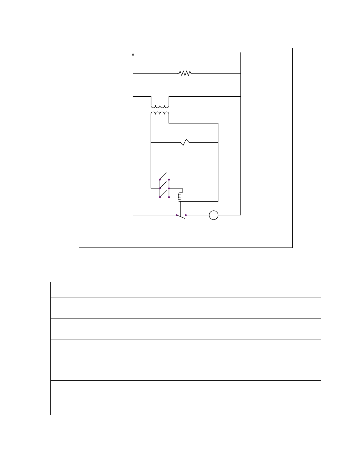
Line
VAC
All Heater Tapes (Original and
Redesigned Models)
(Heater Tapes have been removed from
return lines in Redesigned Models)
24
VAC
Solenoids
(Redesigned Models Only)
Micro-switches
Pump Relay
Coil
Pump Motor
M
Pump Motor Switch
FootPrint III Wiring Diagram
Operation of the redesigned FP-III system is the same as for the original design.
ORIGINAL VS REDESIGNED FP-III FILTRATION SYSTEM
Original System Redesigned System
Return lines and manifolds wrapped with silicone
strip heaters and aluminum tape.
Filter base assembly connected to unit with a
black, heated return hose beneath the filter.
Filter base assembly equipped with swivel
casters.
Operator-removable filter base assembly. (Filter
base assembly stop-locks in cabinet can be
rotated to remove tray.)
Oil/shortening remains in return lines when filter
system is turned off.
Return drain-manifolds are constructed with pipe
nipples, elbows and other plumbing components.
No heater strips or aluminum tape on return
lines.
Non-heated Teflon hose with a swivel joint
connects the filter base assembly to the unit
above the filter.
Filter base assembly has no casters.
Filter base assembly is not removable except by
a qualified service technician. (Filter base
assembly stop-locks fitted with a screw and nut
to prevent filter removal.)
Oil/shortening drains back to the filter pan when
filter system is turned off, leaving no oil or
shortening in return lines.
Return drain manifolds are one-piece with an inline solenoid valve to facilitate drain to filter pan.
1-15
Page 20
Line VAC
Transformer
24VAC
Microswitches
Pump Relay Coil
Pump Motor
M
Relay Contacts
Pump Heater
Filter Magic Simplified Wiring Diagram
1-16
Page 21
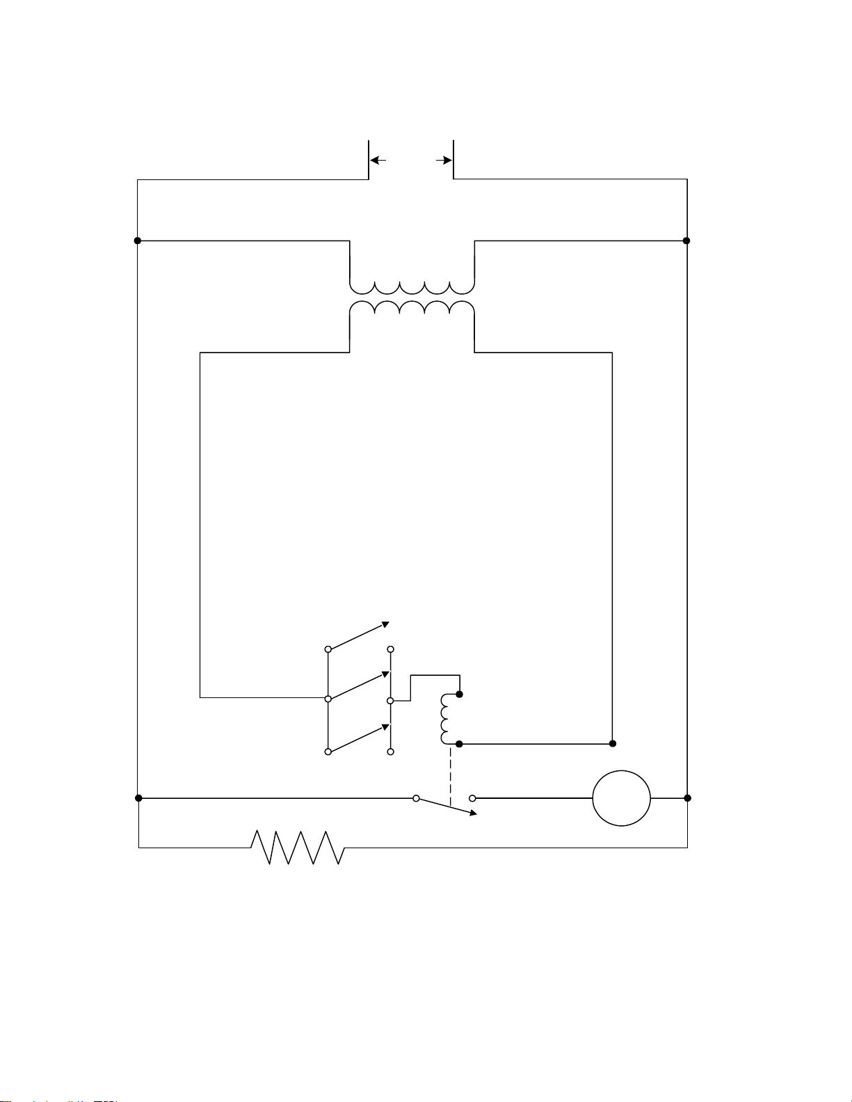
1.11 Basket Lift Service Procedures
H14/H17/H22 Series fryers may optionally be equipped with automatic basket lifts to ensure
uniform cooking times. Basket lifts will always come in pairs, although each operates
independently.
All electric fryers are equipped with “modular” basket lifts.
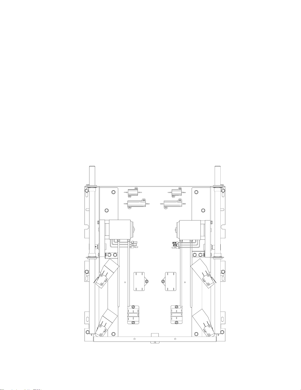
A modular basket lift (illustrated below) consists of a toothed rod to which the basket lift arm is
attached, a reversible-drive gear motor, and a pair of roller-activated microswitches. The gear motor
engages the teeth in the rod, moving it up or down, depending upon the direction of rotation of the
motor. Microswitches at the upper and lower limits of movement stop the motor when the basket is
in the full up or full down position.
Timing circuitry in the controller initiates and stops basket lift operation depending upon the
variables programmed by the operator. When the product button is pressed, the timing circuitry
activates a coil in the basket lift relay to supply power to the lower microswitch. The microswitches
stop the motor at the lift’s upper and lower travel limits and reverse the direction of current flow thus
reversing the motor direction.
Modular Basket LIft Assembly (Typical)
1-17
Page 22
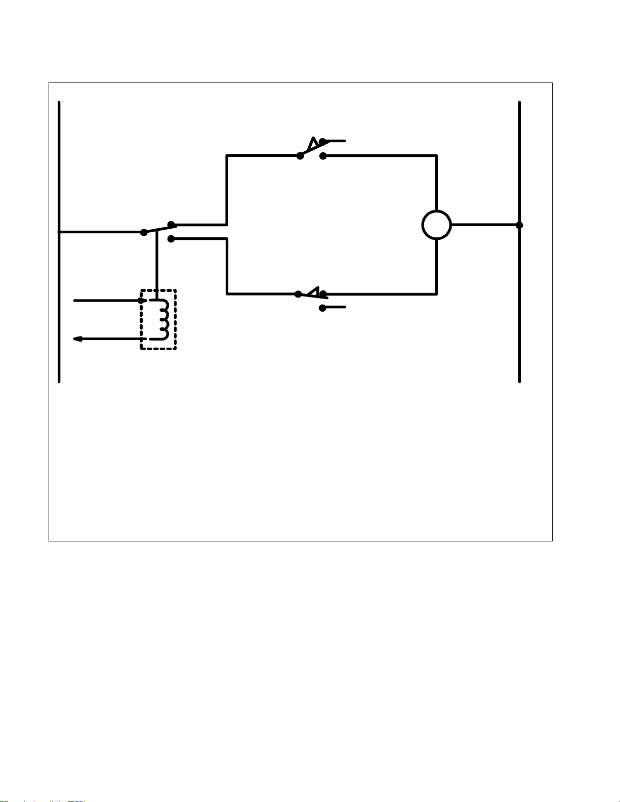
Simplified Schematic
H
5
1 or 4
3
To computer/controller via
interface board
Basket Lift
Relay
Normally Open Upper-limit
Microswitch
M
Normally Closed Lower-limit
Microswitch
N
6
When the product button is pushed on the computer/controller, current flows through a coil
in the basket lift relay, causing the lower circuit to be activated. The basket lift lowers,
closing the normally open upper-micro-switch. When the lower normally closed microswitch is opened by the downward moving lift rod, power to the motor ceases to flow.
When the computer/controller times-out, the current to the relay coil is cut, allowing the
upper circuit to be activated. The basket lift then raises and re-closes the lower microswitch. When the basket lift rod clears the upper micro-switch, the micro-switch reopens
and power to the circuit is cut and the motor stops. Pushing the product button restarts the
cycle.
Problems with the modular basket lift design can be grouped into three categories:
●
Binding/jamming problems
● Motor and gear problems
Electronics problems
●
1-18
Page 23

BINDING/JAMMING PROBLEMS
Noisy, jerky or erratic movement of the lifts is usually due to lack of lubrication of the rods and their
bushings. Apply a light coat of Lubriplate® or similar lightweight white grease to the rod and
bushings to correct the problem.
With the modular basket lift, another possible cause of binding is improper positioning of the motor,
which prevents the gear from correctly engaging the teeth in the rod. To correct the problem, loosen
the screws that hold the motor in place and move it forward or backward until the rod has just
enough slack to be rotated slightly.
MOTOR AND GEAR PROBLEMS
With the modular basket lift, the most likely problem to be encountered in this category is erratic
motion of the lift due to a worn drive gear. Failure to keep the lift rod and bushings properly
lubricated will cause unnecessary wear of the gear. The problem is corrected by replacing the worn
gear.
If the lift cycles correctly but fails to remain in the up position (i.e., goes up, but then slowly settles
back down into the frypot), the problem is a failed motor brake. A failed motor brake cannot be
repaired and requires replacement of the motor itself.
If power is reaching the motor but the motor fails to run, the motor is burned out and must be
replaced.
ELECTRONICS PROBLEMS
Within this category are problems associated with the relays, microswitches, capacitors, resistors,
interface board, wiring, and controls. The most common problem in this category is a lift that
continuously travels up and down. This is usually caused by a microswitch that is out of adjustment.
Troubleshooting the electronics of a modular-type basket lift is simply a process of verifying current
flow through the individual components up to and including the motor. Using a multimeter set to the
250 VAC range, check the connections on both sides of the component for the presence of the
applied line voltage. The accompanying simplified wiring diagrams identify the components and
wiring connection points.
1-19
Page 24
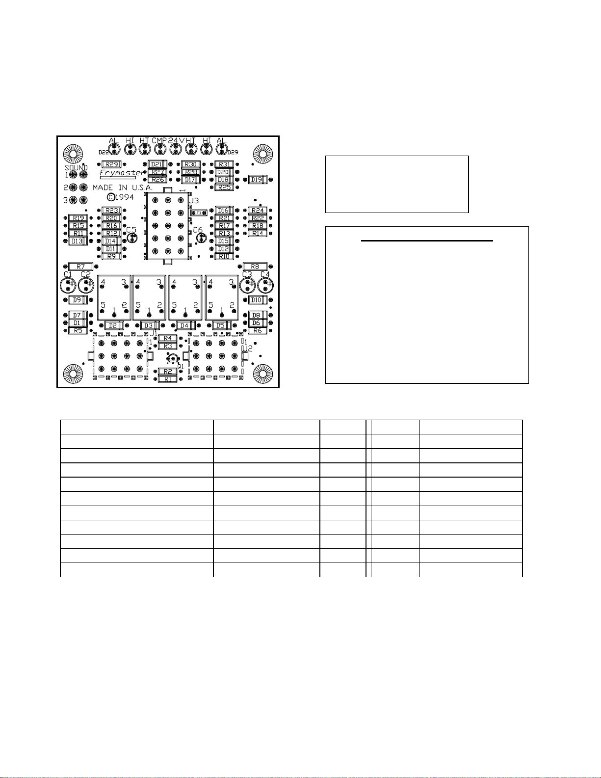
1.12 Electric Interface Board Diagnostic Chart
The following diagram and charts provide ten quick system checks that can be performed using
only a multimeter.
Note: The sealed relays
are not replaceable. If a
relay fails the interface
1
K1
11
12
23
6
5
4
8
7
9
12
11
10
13
15
14
K2
4
7
10
5
8
6
9
1
2
3
K3 K4
10
11
12
4
1
7
5
2
8
6
3
9
board must be replaced.
Diagnostic LED Legend
CMP indicates power from 12V transformer
24 indicates power from 24V transformer
HI (RH) indicates output (closed) from right latch
relay
HI (LH) indicates output (closed) from left latch
relay
HT (RH) indicates output from right heat relay
HT (LH) indicates output from left heat relay
AL (RH) indicates output (open) from right latch
relay
AL (LH) indicates output (open) from left latch
relay
Meter Setting Test Pin Pin Results
12 VAC Power 50 VAC Scale 1 of J2 3 of J2 12-16 VAC
24 VAC Power 50 VAC Scale 2 of J2 Chassis 24-30 VAC
*Probe Resistance (RH) R X 1000 OHMS 11 of J2 12 of J2 See Chart
*Probe Resistance (LH) R X 1000 OHMS 3 of J1 2 of J1 See Chart
Hi-Limit Continuity (RH) R X 1 OHMS 7 of J2 4 of J2 0 - OHMS
Hi-Limit Continuity (LH) R X 1 OHMS 4 of J1 7 of J1 0 - OHMS
Latch Contactor Coil (RH) R X 1 OHMS 8 of J2 Chassis 3-10 OHMS
Latch Contactor Coil (LH) R X 1 OHMS 5 of J1 Chassis 3-10 OHMS
Heat Contactor Coil (RH) R X 1 OHMS 9 of J2 Chassis 18-25 OHMS
Heat Contactor Coil (LH) R X 1 OHMS 6 of J1 Chassis 18-25 OHMS
*Disconnect 15-Pin harness from the computer/controller before testing the probe circuit.
1-20
Page 25
1.13 Simplified Wiring Diagrams, Common Electric
CONTROL CIRCUIT
COMMON ELECTRIC H14/H17/H22 SERIES— FULL-VAT
FUSES
312
GND
3 PHASE POWER TERMINALS
1C
LATCHING
CONTACTOR
2
3
2C
1
HEATING
CONTACTOR
L3
L2
HT
C6-8
J2-9
SD
COMPUTER/CONTROLLER
J3
11
11
HEAT
4
4
T
M
L1
J2
C1-8
J2-8
HI
K3
HEAT
RELAY
C6
TEMP
PROBE
HIGH
LIMIT
24V
12V
7
6
24V
DRAIN
SAFETY
FIRE
CUT-OFF
11 122147
FUSE
SWITCH
3
10
J2
24V
AL
K4
LATCH
RELAY
COMP
13
14
14
10
10 13
5
3
3
1
1
2
25
TROUBLE
ON/OFF
POWER ON
J3
1-21
INTERFACE
BOARD
Page 26
L3
L2
GND
312
1C
LATCHING
CONTACTOR
3
2
2C
1
HEATING
CONTACTOR
C6-8
SD
3 PHASE POWER TERMINALS
L1
J2-8
C6
TEMP
PROBE
67
11 121
24V
HIGH
LIMIT
12V
HIGH
LIMIT
DRAIN
DRAIN
2
SAFETY
SWITCH
47
3
SAFETY
SWITCH
7
HI
24V
COMP
J2-5
K3
HEAT
RELAY
AL
K4
LATCH
RELAY
J2-9
HT
J3
11
11
4
14 1310
5
3
1
HEAT
T
M
14 4
10 13
5
3
1
TROUBLE
ON
POWER
ON
POWER
TEMP
COMMON ELECTRIC H14/H17/H22 SERIES— DUAL-VAT
4
J1 J2
PROBE
1213
C6
32
J1
J2-10
HI
J1-5
K1
LATCH
RELAY
AL
K3
HEAT
RELAY
HT
J1-6
2
2614
12
14
15
15 12
6
J3
TROUBLE
T
M
HEAT
C6-14
HEATING
2
3
3C
LATCHING
CONTACTOR
1
2
3
1
CONTACTOR
4C
COMPUTER/
CONTROLLER
1-22
Page 27

COMMON ELECTRIC H14/H17/H22 SERIES- TRIAC— FULL-VAT
FUSES
CONTROL CIRCUIT
3 PHASE POWER TERMINALS
L3
L2
L1
GND
TEMP
HIGH
2C
C1-11
HT
HEATING TRIACS
C1-9
C6-9
SD
C6-8
COMPUTER/
CONTROLLER
J3
J2-9
11
11
HEAT
4
4
T
M
312
J2
1C
C1-8
HI
LATCHING
CONTACTOR
J2-8
hi relay
J2-5
C6
PROBE
7
6
11 122147
24V
24V
FUSE
24V
LIMIT
12V
DRAIN
SAFETY
SWITCH
3
10
FIRE
CUT-OFF
COMP
K4
AL
LATCH
RELAY
J2
13
13
14
14
10
10
5
5
3
3
1
1
2
2
TROUBLE
ON/OFF
POWER ON
J3
1-23
INTERFACE
BOARD
Page 28

Burn-off Relay option was
discontinued on all Common
Electric fryers manufactured after
mid-98, and is no longer required
for use.
C
GND
312
N
1C
LATCHING
CONTACTOR
2
3
L3
2C
1
HEATING
CONTACTOR
TILT SWITCH
L2L1
NO
BURN-OFF RELAY
NC
COMMON ELECTRIC H14/H17/H22 SERIES— FULL-VAT— EXPORT WYE
3 PHASE POWER
TERMINALS
TEMP
HIGH
C1-8
J2
HI
24V
HI RELAY
J2-8
COMP
K3
HEAT
RELAY
AL
K4
LATCH
RELAY
12 VDC
Control Circuit
Fuses
C6
12
7
PROBE
6
11
24V
LIMIT
12V
21
DRAIN
SAFETY
SWITCH
7
4
3
FIRE
10
CUT-OFF
J2
HT RELAY
SD
J3
11
11
J2-6
J2-9
J2-5
HT
HEAT
4
4
13
13
14
14
1/50
1K
47K
A
4.7K
10
10
5
5
7
7
3
3
1
1
2
2
T
M
TROUBLE
BURN
OFF
POWER ON
COMPUTER/CONTROLLER
ON/OFF
J3
1-24
INTERFACE
BOARD
Page 29

C
NO
RELAY
BURN-OFF
NC
M
Burn-off Relay option was discontinued on all Common Electric fryer s
manufactured after mid-98, and is no longer required for use.
COMPUTER/CONTROLLER
T
M
L3
GND
312
1C
LATCHING
CONTACTOR
3
2
2C
1
HEATING
CONTACTOR
TILT
SWITCH
L2
L1
TERMINALS
TEMP
HIGH
HIGH
N
J2-8
HT
K3
HEAT
RELAY
C6
PROBE
67
11 121
24V
FUSE
24V
LIMIT
12V
2
DRAIN
SAFETY
SWITCH
47
3
J2
LIMIT
DRAIN
SAFETY
SWITCH
7
4
HI
24V
COMP
AL
K4
LATCH
RELAY
K1
LATCH
RELAY
1/50
10K
3 PHASE POWER
J1
1/50
TEMP
PROBE
1213
C6
J1 32
HI
AL
SD
J2-6
J3
J2-9
J2-5
1K
47K
A
A
1K
47K
11
11
4
4
1310
14
14
10 13
5
5
3
3
1
1
9
9
2
2614
12
14
15
15 12
6
HEAT
T
TROUBLE
BURN
OFF
POWER
ON
BURN
OFF
POWER
ON
TROUBLE
COMMON ELECTRIC McDONALD'S H14 SERIES— DUAL-VAT— EXPORT WYE
K2
HEAT
J2-10
2
3
J1-5
1
3C
LATCHING
CONTACTOR
3
RELAY
HT
J1-6
2
1
J3
HEAT
J1-9
C
NO
TILT
RELAY
4C
HEATING
CONTACTOR
SWITCH
BURN-OFF
NC
1-25
Page 30

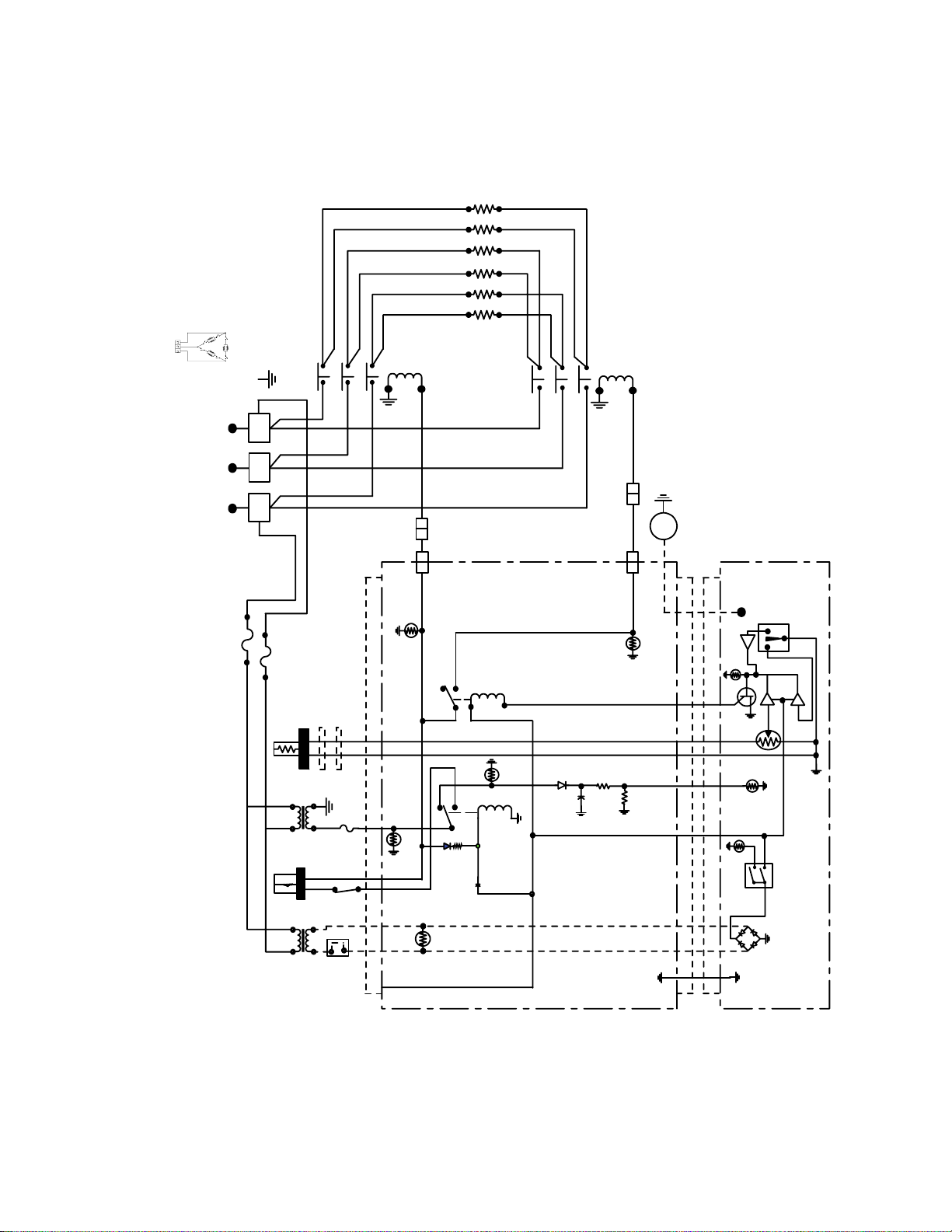
1.14 Wiring Diagrams, Main
Domestic Wiring Diagram
1-26
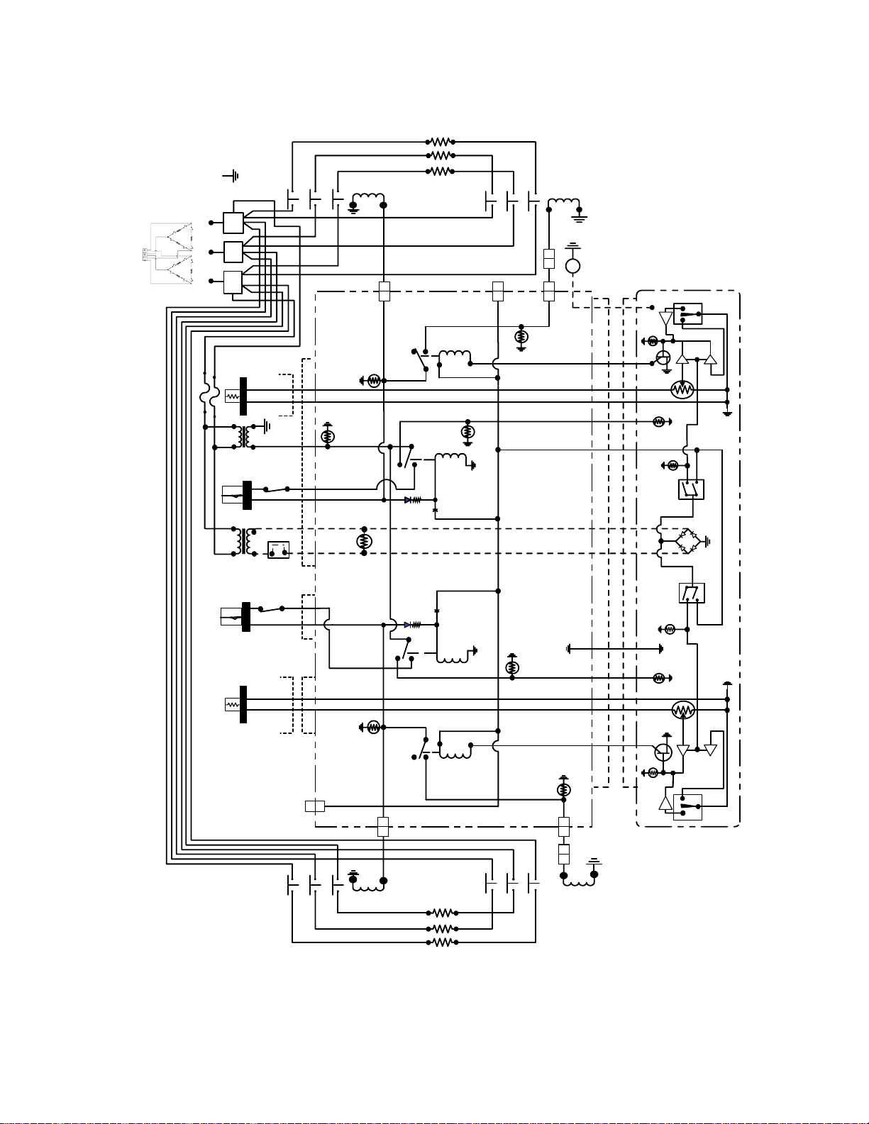
Page 31

FPH114/117/122 CE Wiring Diagram
1-27
Page 32

Delta Wiring Diagram
1-28
Page 33

WYE Wiring Diagram
1-29
Page 34

Delta 480V Non-filter Wiring Diagram
1-30
Page 35

Delta 480V With FootPrint/Filter Magic II Wiring Diagram
1-31
Page 36

1.15 Wiring Diagrams, Basket Lifts
Modular Basket Lift, 100—120V w-Relay Wiring Diagram
1-32
Page 37

1.15 Wiring Diagrams, Basket Lifts (cont.)
Modular Basket Lift, 208—250V w-Relay Wiring Diagram
NOTE: Some units will have four 50ohm resistors rather than two 100ohm resistors.
1-33
8050888C
Page 38

1.16 Wiring Diagrams, Filtration Systems
Filter Magic II (Prior to October 98)
Eliminated on Filter Magic
II systems manufactured
after 10/98
1-34
Page 39

Filter Magic II (October 98 and later)
1-35
Page 40

Footprint III, Early Configuration.
3C
NOTE: REFER TO ABOVE CHART
FOR LINE VOLTAGE CONNECTIONS
24
56
3
1
32C
12C
RED
1 2 4 5 6
78
LINE
LOAD
12 1011 9
9
6
852
74
RED
8C
41C
30C
3
1
45C
52C
RED
NOTE: USE TERMINALS 7 AND 8 FOR 24V OUTPUT.
USE TERMINALS 11 AND 12 FOR 12V OUTPUT.
92C
TO PIN 7
TO PIN 9
VOLTS LINE
100
9
7
8
4
6
5
3
2
1
TO PIN 4
TO PIN 6
TO PIN 1
TO PIN 3
12011
208
220
230
BLACK
WHITE
BLACK
WHITE
10C
11C
9C
62C
T2T1
COM
1
1
1
1240
HOSE
HEATER
4
6
2
4
5
6
PUMP
HEATER
LINE
HEATER
(OPTIONAL)
FILTER WIRING DIAGRAM
NON-REVERSING PUMP
Footprint III, Late Configuration
13
24
108C
11C
RED
RED
12C
LINE
9C
26C
13C
TO PUMP
MOTOR
8050538H
TO PIN 1
TO PIN 3
TO PIN 7
TO PIN 9
32C
45C
52C
T-4
24V/50VA
PUMP
HEATER
PUMP
SOLENOID
T2T1
14C
92C
62C
10C
3
6
2
5
147
4
7
8
5
9
6
9
8
27C
51C
1
2
3
8C
41C
30C
13C
FILTER BOX WIRING DIAGRAM
1-36
26C
9C
TO PUMP
MOTOR
8050902C
Page 41

H14/H17/H22 SERIES ELECTRIC FRYERS
2.1 Accessories
CHAPTER 2: PARTS LIST
1
3
4 5
2
6 7
ITEM PART # COMPONENT
1 803-0209 Brush, FV/DV Frypot
2 803-0046 Cup, Measuring, Plastic, #1040
3 803-0197 Fryer Friend 27-inch (Clean-out Rod)
4 803-0099 Basket, Full-vat
* 803-0271 Basket, Dual-vat
5 803-0113 Sediment Tray, Full-vat
* 803-0122 Sediment Tray, Dual-vat, Left
* 803-0123 Sediment Tray, Dual-vat, Right
6 803-0106 Rack, Electric Dual-Vat Basket Support
7 803-0132 Rack, H50 Full-Vat With Probe Guard Basket
* 803-0002 Carton, Filter Powder
* 803-0170 Filter Pack– 100 Sheets
* 806-3068 Cover, Full Vat Frypot
* 806-3071 Cover, Dual Vat Frypot
* Not illustrated.
2-1
Page 42

2.2 Basket Lift Assemblies and Component Parts
15
16
2
14
1
8
5
6
12
7
3
10
11
13
9
4
2-2
Page 43

ITEM PART # COMPONENT
Common Components
1 813-0035 Bushing, Bronze, .640-inch ID
2 901-8499 Chassis, Modular Basket Lift, Left
3 902-8499 Chassis, Modular Basket Lift, Right
4 807-0158 Connector, 6-Pin Female, Panel Mount
5 900-5529 Gusset, Modular Basket Lift Motor
6 812-0442 Insulation, Microswitch
7 807-2572 Microswitch
8 806-5964SP Motor Assembly, Modular Basket Lift
9 200-2942 Mount, MBL (for old mount w/6-pin plug use 900-7655)
10 809-0082 Ring, Retaining – Truarc
11 810-1012 Rod, Modular Basket Lift
* 823-2704 Left Basket Lift Arm
* 823-2705 Right Basket Lift Arm
12 807-2133
Capacitor, 12.5 μFarad, 250VAC Motor
Resistors
13 807-1683 Relay, 12V (All Basket Lifts w/Relays)
14 806-9185 Resistor Assembly, Modular Basket Lift (used in 806-8532SP)
15 806-8530 Resistor Assembly, Modular Basket Lift (used in 806-8531SP)
16
Resistor Assembly, Modular Basket Lift (see NOTE below)
106-2770 200-220V (used in 806-8086SP and 806-8685SP)
106-2771 230-250V (used in 806-8087SP and 806-8686SP)
Wire Assemblies
WIR00482 For 106-1807SP (for 6-pin MBL assembly 806-8531SP, use WIR0073SP)
WIR0292 For 806-8532SP
WIR0166 For 806-8086SP & 806-8087SP
806-8555SP For 6-pin assemblies 806-8685SP & 806-8686SP
106-1804SP For 12-pin assemblies 106-1809SP & 106-1810SP
Complete Assemblies
106-1807SP 100/120V w/o Relay (for 6-pin assembly, use 806-8531SP)
106-1808SP 100/120V w/Relay (for 6-pin assembly, use 806-8532SP
106-1809SP 200/208/220V w/o Relay (for 6-pin assembly, use 806-8685SP
106-1805SP 200/208/220V w/Relay (for 6-pin assembly, use 806-8086SP
106-1810SP 230/240/250V w/o Relay (for 6-pin assembly, use 806-8686SP
106-1806SP 230/240/250V w/Relay (for 6-pin assembly, use 806-8087SP
* Not illustrated.
NOTE: Item 16 replaces all previous resistors and resistor assemblies used in 200-250V modular
basket lifts.
2-3
Page 44

2.3 Cabinet Assemblies and Component Parts
2.3.1 H114/117/122 Cabinet Assembly, Single FootPrint and Non-Filter
8
6
3
4
7
1
2
5
2-4
Page 45

ITEM PART # COMPONENT
1 806-4910SP Rail Assembly, Single FootPrint
* 200-0129 Rail, Top Front Single Common Electric N/F
2 806-4897SP Base, Single FootPrint
* 806-7003SP Base Assembly, Single Common Electric, N/F
3 900-4393SP Brace, Top, Single FootPrint
4 900-4391SP Brace, Cabinet Front
* 900-2733 Brace, Contactor Box, Front, N/F
* 900-2734 Brace, Support Contactor Box, Common Electric, N/F
* 200-0130 Brace, Rear Horizontal, Common Electric, N/F
* 201-0137 Upright- rear enclosure, Common Electric, N/F
* 202-0137 Upright- rear enclosure, Common Electric, N/F
5 Side, Cabinet – Left Side
911-9314 Stainless Steel
901-9314 Enameled Steel
6 Side, Cabinet – Right Side
912-9314 Stainless Steel
902-9314 Enameled Steel
* 910-2456SP Cabinet Side, Common Electric N/F
7 900-1621 Plate, Rail Mount
8 910-2912 Back, Upper Cabinet, Single FootPrint
* 900-5204 Back, Cabinet, 22kW Single FP
* 900-4412 Bracket, Component, 22kW Single FP
* 900-2717SP Back, Upper Cabinet, Common Electric, N/F
* 900-5141 Back, Center Cabinet, MH114
* 900-8449 Back, Lower Cabinet with U-shaped Cutout
* 200-4581 Back, Lower Cabinet without U-shaped Cutout
* 910-7925 Leg, Cabinet, Front Filter
* 900-9585 Heat Shield, Wire, Common Electric
* 826-1374 Screw, #10-1/2 Hex Head (Pkg. of 25)
* 826-1389 Screw, ¼-20 x ¾ Hex Head (Pkg. of 10)
* 826-1334 Bolt, ¼-20 X 1 ¼ Hex Head (Pkg. of 5)
* 826-1368 Nut, Flange ¼-20 Serrated (Pkg. of 10)
* 809-0070 Nut, Hex ¼ x 20 SS
* 809-0191 Washer, Lock, ¼-inch
* Not illustrated.
2-5
Page 46

2.3.2 H114/117/122 Cabinet Assembly, Battered Option—Filter Ready
9
2
8
7
11
13
3
1
5
10
4
6
12
14
ITEM PART # COMPONENT
1 806-4897 Base, Single FP
2 806-5317 Filter Rail Assembly, Single FP
3 809-0361 Screw, 8 x ½ Hex
4 809-0412 Screw, #10-½ Hex
5 900-1786 Motor Mount, Cantilever Bracket
6 900-4391 Brace, Cabinet Front
7 900-4551 Motor Mount, Single FootPrint
8 900-4813 Brace, Cabinet Top Single
9 900-7448 Back, Top, FPH 50
10 901-1405 Gusset, Cabinet FP-TCF Left
11 902-1405 Gusset, Cabinet FP-TCF Right
12 910-8673 Leg, Front Filter w/Swivel Caster
13 Side, Cabinet, Left
911-9324 Side, Stainless Steel
901-9324 Side, Cold Rolled Steel
14 Side, Cabinet, Right
912-9324 Side, Stainless Steel
902-9324 Side, Cold Rolled Steel
* 910-0889 Cover, 4” x 4” S/S (for enameled steel, use 900-0889)
* 910-0890 Cover, 4” x 6” S/S (for enameled steel, use 900-0890)
* 809-0359 Screw, #8 x ¼” Hex Washer Head
* Not illustrated.
2-6
Page 47

2.3.3 Filter Magic Under-Counter Cabinetry (after 8/2000)
3
5
9
15
17
See Detail
2
14
7
12 16
1
10
6
8
Detail
11
ITEM PART # COMPONENT
1 201-0483 Side, Cabinet U/C Enameled – Left
2 202-0483 Side, Cabinet U/C Enameled – Right
* 211-0483 Side, Cabinet U/C Stainless Steel – Left
* 212-0483 Side, Cabinet U/C Stainless Steel – Right
3 806-8059 Leg Pad Assembly
4 806-8062SP Filter Rail Assembly, Common Electric FM
5 806-8935SP Base Assembly, FM 3-Piece
6 826-1362 Nut, ¼ - 20 Hex (Pkg. of 10)
7 826-1389 Screw, Hex Head ¼ -20 x ¾ (Pkg. of 10)
8 809-0191 Washer, ¼ Lock
9 826-1374 Screw, #10- ½ Hex Head (Pkg. of 25)
10 809-0429 Bolt, ¼ -20 x 2
11 810-0665 Nut, Leveling
12 823-2827 Mount (Weld Assembly), Common Electric Single FP
13 900-4391 Brace, Cabinet Front
14 900-4785 Brace, Cabinet – Top and Center
15 900-8582 Mount, Motor Single FP Common Electric
16 900-8591 Bracket, Mount Common Electric Single FP
17 910-8659 Leg, Cabinet Front Common Electric Single FP
* Not illustrated.
13
4
2-7
Page 48

2.3.4 FootPrint III, Filter Magic II and Non-Filter Options
4
27
28
1
23
8
3
30
24
21 7 8 13
22
See Detail A
26
See
Detail B
18
11 142
ITEM PART # COMPONENT
1 200-0076 Divider, Cabinet, Common Electric
2 200-0084 Brace, Rear Horizontal, 2 Battery (Quad and Double)
* 200-0085 Brace, Rear Horizontal, 3 Battery (Triple)
3 200-0091 Rail, Top- Quad Cabinet
* 200-0072 Rail, Top- Triple Cabinet
* 200-0081SP Rail, Top- Double Cabinet
4 200-0092 Support, Rear, Common Electric
5 200-0126 Brace, Rear Support
6 200-0138 Door Post, Common Electric
7 201-0093 Enclosure, Rear Upright with Hole (Quad Only)
8 201-0137 Upright, Rear Enclosure, Common Electric
9 202-0093 Enclosure, Rear Upright with Hole (Quad Only)
10 202-0137 Upright, Rear Enclosure, Common Electric
11 806-7005SP Base, Filter Assembly, Common Electric- Quad
* 806-6513SP Base, Filter Assembly, Common Electric- Triple
* 806-6511SP Base, Filter Assembly, Common Electric- Double
* 806-6997SP Base Assembly, Common Electric N/F- Double
* 806-6999SP Base Assembly, Common Electric N/F- Triple
* 806-7001SP Base Assembly, Common Electric N/F- Quad
12 826-1376 Nut, 10-32 (Pkg. of 10)
13 826-1374 Screw, #10 ½-Inch (Pkg. of 25)
Continued on following page.
5
32
Detail B
25
10
6
29
31
17 16
20
12
Detail A
19
15
2-8
Page 49

ITEM PART # COMPONENT
14 809-0413 Spacer, Door Post (Quad and Triple Only)
15 809-0422 Screw, Shoulder- 10-32 x .40
16 809-0538 Bolt, Shoulder- ¼-20 x 3/8
17 823-2290 Front Bridge Support, Left
18 823-2291 Front Bridge Support, Right
19 900-1957 Lock Filter
20 900-1959 Bracket, Mounting, Filter Lock
21 900-2463 Post, Center Door, Common Electric
22 900-2464SP Brace, Lower, Front Horizontal, Common Electric
23 900-2514 Bridge, Common Electric
24 900-2653 Plate, Swivel, Common Electric
25 900-2718 Brace, Contactor, Front, Common Electric w/Filter-Quad
* 200-0078 Brace, Contactor, Front, Common Electric [(w/Filter-Triple), N/F- Quad)]
* 200-0075 Support, Contactor, Front, Common Electric N/F
26 900-2720 Brace, Contactor, Rear, Common Electric-Quad
* 200-0077 Brace, Contactor, Rear, Common Electric [(w/Filter-Triple), N/F- Quad)]
* 200-0074 Support, Contactor, Rear, Common Electric N/F
27 900-2861SP Support, Bottom, Common Electric
28 900-5988 Support, Rear, Bridge Filter, Common Electric
29 901-1810 Gusset, Cabinet, Left
* 902-1810 Gusset, Cabinet, Right
30 901-1948 Channel, Side Support
31 910-2456SP Side, Cabinet – Stainless Steel, Common Electric
* 900-2456SP Side, Cabinet – Enameled Steel, Common Electric
* 901-2843SP Side, FM Common Electric w/Cut-out Left Cabinet, Enameled Steel
* 902-2843SP Side, FM Common Electric w/Cut-out Right Cabinet, Enameled Steel
* 911-2843SP Side, FM Common Electric w/Cut-out Left Cabinet, Stainless Steel
* 912-2843SP Side, FM Common Electric w/Cut-out Right Cabinet, Stainless Steel
* 900-8451 Back, Lower Triple
* 900-8450 Back, Lower Double
* 900-5145 Back, Center Triple
* 900-5143 Back, Center Double
* 900-9635 Back, Upper Triple
* 900-9637 Back, Upper Double
32 900-9585 Heat Shield, Wire, Common Electric
* Not illustrated.
2-9
Page 50

2.3.5 Common Electric Filter Magic Unitary Cabinetry (after 8/2000)
See Detail "A"
67 8
25
1213 14
11
22
123 4
910
5
24
See Detail "B"
Detail "A"
19
16
17
21
18 20
15
Detail "B"
26
23
28
27
2-10
Page 51

ITEM PART # COMPONENT
1 106-0215 Base Assembly, Quad—FM Common Electric (1F24)
* 106-0217 Base Assembly, Quad—FM Common Electric (31F2)
* 106-0218 Base Assembly, Quad—FM Common Electric (531F)
* 106-0220 Base Assembly, Quad—FM Common Electric (F246)
* 106-0214 Base Assembly, Triple—FM Common Electric (1F2)
* 106-0216 Base Assembly, Triple—FM Common Electric (31F)
* 106-0219 Base Assembly, Triple—FM Common Electric (F24)
* 106-0221 Base Assembly, Double—FM Common Electric (F2)
* 106-0222 Base Assembly, Double—FM Common Electric (1F)
2 200-0020 Shield, Filter Magic Pan CE
3 200-0074 Support, Rear Contactor Box
4 200-0075 Support, Front Contactor Box
5 200-0076 Divider, Cabinet Common Electric
6 200-0077 Brace, Rear Contactor Box
7 200-0078 Brace, Front Contactor Box Common Electric
8 200-0091 Brace (Rail), Top Quad Common Electric
* 200-0072 Brace (Rail), Top Triple Common Electric
* 200-0081SP Brace (Rail), Top Double Common Electric
9 200-0092 Support, Rear Common Electric
10 200-0126 Brace, Rear Support
11 200-0138 Doorpost, Common Electric
12 200-0343 Brace, Rear Horizontal-Quad Common Electric
* 200-0085 Brace, Rear Horizontal-Triple Common Electric
* 200-0084 Brace, Rear Horizontal-Double Common Electric
13 201-0137 Upright, Rear Enclosure, Left, Common Electric
14 202-0137 Upright, Rear Enclosure, Right, Common Electric
15 806-8062SP Filter Rail Assembly, Common Electric FM
16 826-1362 Nut, ¼ - 20 Hex (Pkg. of 10)
17 809-0191 Washer, ¼ Lock
18 826-1374 Screw, #10 - ½ Hex (Pkg. of 25)
19 809-0429 Bolt, ¼ - 20 x 2
20 826-1379 Screw, #10 x ½ Phillips (Pkg. of 10)
21 810-0665 Leveling Nut
22 900-2861SP Support, Bottom Common Electric
23 900-4391SP Brace, Cabinet Front
24 900-8582 Mount, Motor- Single FP Common Electric
25 910-2456SP Side, Cabinet—Stainless Steel Common Electric
* 900-2456SP Side, Cabinet—Cold Rolled Steel Common Electric
26 826-1389 Screw, Hex Head— ¼-20 x ¾ (Pkg. of 10)
27 823-2827 Mount (Weld Assembly) Common Electric Single FP
28 900-8591 Bracket, Mount – Common Electric Single FP
* Not illustrated.
2-11
Page 52

2.4 Casters, Legs and Associated Hardware
1 2 3 4
6 7
8
5
9 10
11 12 13
14
19
15
2016 17 18
2-12
Page 53

ITEM PART # COMPONENT
1 810-0005 Caster, Rigid
2 810-0006 Caster, Swivel-Rokite
3 810-0327 Caster, Adjustable, Without Brake
4 810-1565 Caster, Stud, Single FP 3-inch, With Lock
* 823-2844 Caster, With Brake – Single FP Electric
5 810-0944 Caster, Adjustable 3-inch With Brake
6 810-0356 Caster, 5-inch Wheel Without Brake
7 810-0357 Caster, 5-inch Wheel With Brake
8 810-0651 Caster w/Brake –FootPrint II
9 810-1239 Caster, 8.5-inch Swivel w/Brake (for Cracker Barrel units, use 810-2737)
10 810-1242 Caster, 8.5-inch Rigid
11 810-1367 Caster, Adjustable 3-inch w/o Brake
12 810-1494 Caster, 8.5-inch Swivel w/o Brake (for Cracker Barrel units, use 810-2738)
13 810-1365 Caster, Adjustable 3-inch w/Brake
14 810-0378 Caster, Stationary Rigid, 5-inch Wheel
15 826-0900 Chain Restraint Kit (for use on fryers w/casters)
16 806-3811 Leg, Package (4 per set)
17 810-0007 Leg, Adjustable (For 1 ¼-inch square tubing)
18 826-1234 Leg, Adjustable, 8.5-inch (with hardware)
19 810-1414 Insert, Square Leg, Baby FootPrint
* 910-7925 Leg ,Single FootPrint w/Caster Front Filter
* 910-1601 Leg, Square, Filter Cabinet Front
* 910-8659 Leg, Cabinet Front— Common Electric Single FootPrint
20 900-2941 Strap, Anchor—Common Electric
* 900-1835 Strap, Anchor—Single Fryers with Legs
* Not illustrated.
2-13
Page 54

2.5 Component Box Assemblies and Associated Hardware
8
6
3
123
456
789
10
13
1415
1112
2
4
119
1
5
7
ITEM PART # COMPONENT
1 810-1164 Terminal Block Wire Assembly
2 806-8244 Component Box/Stud Assembly
3 Transformer, 12VAC
807-2191 208-240 V
807-0979 208-240V
807-2192 100-120V
807-0855 120V, 20VA
4 Transformer, 24VAC
807-0680 208-240 V (without fuse)
807-2180 208-240 V (with fuse)
807-2181 100-120V, 62VA (with wires)
807-0800 120V, 50VA (without wires)
* 807-1999 12/24 VAC Transformer, 208/220/230/240, 20/50 VA (Single FootPrint)
5 Interface Board
806-6336 Standard Models
806-3850 HE EF Models w/Rear Probe
806-6347 Solid State (Triac) Models
106-2982 Fast Computer
* 807-3932 Relay, Heat/Latch 12VDC SPDT 12A
6 807-1084 Bushing
7 806-6854SP Wiring Assembly, Transformer
8 806-7179SP Sound Device
9 826-1337 Terminal Tab (Pkg. of 5)
10 806-2071 Cable Assembly, Computer/Interface Board
* Not illustrated.
10
10
9 8 7
6 5 4
3 2 1
15 141312 11
2-14
Page 55

2.6 Control Panel Assemblies, Doors, and Related Components
2.6.1 Control Panel Assemblies, Top Caps, and Associated Components
4
10
1
9
6
8
2
3
5
7
ITEM PART # COMPONENT
1 Control Panel Assembly
806-7171SP Single Fryer
806-7172SP Two-Fryer Battery
806-7173SP Three-Fryer Battery
806-7174SP Four-Fryer Battery
106-2171SP Five-Fryer Battery
106-2324SP Applebee’s Fryer with Dump Station on Left
106-2325SP Applebee’s Fryer with Dump Station on Right
2 823-2307 Control Panel Bezel, with Slot
3 823-0768 Control Panel Bezel, without Slots (for Digital and Analog Controllers)
4 Topcap
106-3034SP Single Non-Filter
824-0409 Single FootPrint (requires Item 9 also)
106-3033SP Double
106-3035SP Triple
106-3036SP Quad Common Electric
824-1037 5-Battery (requires Item 9 also)
824-1047 Applebee’s Fryer with Dump Station on Left (requires Item 9 also)
824-1048 Applebee’s Fryer with Dump Station on Right (requires Item 9 also)
5 Tilt Housing
824-0791 Single
824-0789 Double
824-0798 Triple
824-0799 Quad
824-0852 5-Battery
6 Basket Hanger, Aluminum (No longer available, use Item 7)
7 810-1403 Basket Hanger, Wire
8 809-0171 Screw, Basket Hanger
9 826-1351 Cage Nut (Pkg. of 10) (receives Basket Hanger Screw)
10 823-1885 Top Connecting Strip
2-15
Page 56

2.6.2 Door Assembly Components
5
4
3
2
1
6
7
8
ITEM PART # COMPONENT
806-6545SP Door Assembly, Universal
1 809-0266 Screw, #10- ½-inch
2 824-0137SP Panel, Door
3 806-4487SP Door Pin Assembly
* 809-0193 Washer, Flat ¼-Inch Nylon (Door Pin Bushing)
4 826-1343 Spring, Door Hinge (Pkg. of 10)
5 900-2485 Liner, Door
6 810-1422 Handle, Wireform, Door
7 810-1105 Magnet, Door
8 810-1508 Hinge, Universal Door
* Not illustrated.
2-16
Page 57

2.7 Controller Assemblies
1
3
ITEM PART # COMPONENT
1
Computer Magic III
106-1193 Full-vat (CE)
106-1194 Dual-vat (CE)
806-7158 Full-vat (Domestic)
806-7159 Dual-vat (Domestic)
806-7162 Full-vat (Triac/Solid-State)
806-7163 Dual-vat (Triac/Solid-State)
2
Analog Controller
806-7422 Full-vat
806-7423 Dual-vat
3
Basket Lift Timer
106-2090SP Full-vat (CE)
106-2091SP Dual-vat (CE)
106-2088SP Full-vat (Domestic)
106-2076SP Dual-vat (Domestic)
4
Digital Controller
106-1507 Full-vat (CE)
106-1508 Dual-vat (CE)
106-1503 Full-vat (Domestic)
106-1952 Dual-vat (Domestic)
2
4
2-17
Page 58

2.8 Electrical Components
2.8.1 Contactor Box Components, Mercury Contactor
12
13
14
2
8
7
6
5
4
9
15
16
17
9
111
10
3
1
2-18
Page 59

ITEM PART # COMPONENT
1 900-5445 Front Cover, Contactor Box
2 900-5446 Top Cover, Contactor Box
3 807-0922 Holder, Buss Fuse
* 807-2278 Fuse, 20 Amp
* 807-2279 Fuse, 15 Amp
* 807-0501 Fuse Block 3-Pole Buss (22kW)
* 807-2240 Fuse 60 Amp (22kW)
* 807-2865 Block Support, Fuse (22kW)
4 816-0217 Paper, Insulating Terminal Block (CE)
5 810-1164 Terminal Block
6 807-1973 Terminal Post
7 C1 Wiring Assembly
806-7198SP For Dual-vat Applications
806-7199SP For Full-vat Applications
8 807-2464 Power Block, Delta
* 807-2465 Power Block, WYE
9 810-1202 Contactor, 3-Pole 600V 40 Amp
10 C2 Wiring Assembly
806-7191SP Dual- and Full-vat
11 807-1071 Contactor, Mercury 24 VAC 30 Amp
* 807-0884
Contactor, Mercury 24 VAC 50 Amp (See NOTE)
12 806-7183SP Wire Assembly, Left, Dual-vat
* 806-7186SP Wire Assembly, Left, Full-vat
* 807-2136 Connector, 6-Pin Female
* 807-2135 Connector, 6-Pin Male
13 806-7185SP Wire Assembly, Right (Full- and Dual-vat)
* 807-2138 Connector, 9-Pin Female
* 807-2137 Connector, 9-Pin Male
14 807-0070 Terminal, Ground Lug
15 900-5447 Back Cover, Contactor Box
16 900-5782 Bracket, Connector Common Electric
17 900-5444 Box, Contactor Common Electric
* Not illustrated.
NOTE: For H22 Models using 208-240V, but not 480V.
2-19
Page 60

2.8.2 Contactor Box Components, Solid State Relays (Triac)
21
22
6
19 15
3
9
11
23
10
8
25
2
7
1614
4
24
5
1
18
12
13
2017
26
27
.312 ± .030
.775
Triac
.130 REF.
Circuit Board
28
Triac board for fryers with serial
numbers of 9809XX0000 and lower
(XX is the series code).
2-20
Page 61

ITEM PART # COMPONENT
1 806-7185SP Wire Assembly, HV Right Contactor
* 806-7184SP Wire Assembly, HV Right FV H22 Contactor
2 806-7186SP Wire Assembly, HV Left FV Contactor
* 806-7188SP Wire Assembly, HV Left FV H22 Contactor
* 806-7183SP Wire Assembly, HV Left DV Contactor
3 806-7191 C2 Wire Assembly, Common Electric
4 806-7198 C1 Wire Assembly, Dual-vat Common Electric
* 806-7199 C1 Wire Assembly, Full-vat Common Electric
5 806-8589 Front Assembly, Fuse Contactor Box Common Electric
6 806-8673 Heat Sink Assembly, Full-vat Solid State Relay
* 806-8674 Heat Sink Assembly, Dual-vat Solid State Relay
* 826-1562 Kit, 40A 280V Relay w/Heat Sink Compound
7 806-0070 Terminal, Ground Lug
8 807-0501 Fuse Block, Buss #2968 3-Pole
9 807-0922 Holder, Buss Fuse HPS
10 807-2240 Fuse, Buss 60 Amp 300 VAC
11 807-2278 Fuse, 20 Amp
12 807-2464 Power Block, Delta Common Electric
* 807-2465 Power Block, WYE Common Electric
* 806-9124 Filter Assembly (WYE Solid-State/Triac Contactor Box Only)
13 810-0743 Button, Plug ¾-inch
14 810-1164 Terminal Block, 1 PLC Screwless
* 807-0064 Transformer-150VA, 480V Applications, w/o Basket Lift
* 807-0331 Transformer-250VA, 480V Applications, w/Basket Lift
15 810-1202 Contactor, 3-Pole 600V 40 Amp
16 816-0217 Paper, Insulating Terminal Block CE
17 900-2519 Hinge, Control Box Common Electric
18 900-2752 Plate, Cordset Common Electric
19 900-5782 Bracket, Connector Common Electric Box
20 900-5784 Box, Contactor Common Electric
21 900-5785 Rear, Triac Contactor Box Common Electric
22 900-5786 Rail, 2-Contactor Common Electric
23 900-5797 Support, Fuse Block Common Electric
24 900-5895 Top, Triac Contactor Box Common Electric
25 900-8239 Rear, Split Triac Contactor Box
26 806-5072 Triac Board Assembly (2 required for Dual-vat Applications)
* 812-1283 Heat Sink, Triac Board
27 807-1276 Triac 600/40A TO-218
* 815-0554 Heat Sink Compound (required for installing Triac Board to Heat Sink)
28 807-1337 Standoff, Triac Board
* Not illustrated.
2-21
Page 62

2.8.3 Elements and Related Components
11
1
2
3
Dual Vat Full Vat
4
5
6 7
11
8
9
10
19
18
16
16
Full Vat
12
13
17 14
15
Dual Vat
2-22
Page 63

ITEM PART # COMPONENT
1 826-1339 Bushing, .375 Split (Pkg. of 10)
2 809-0567 Ty-Wrap, Metal
3 Heating Element
807-2639 208V 7 kW
807-2640 208V 8.5 kW
807-2641 220V 8.5 kW
807-2642 230V 7 kW
807-2643 230V 8.5 kW
807-2644 240V 7 kW
807-2645 240V 8.5 kW/ 220V 7 kW
807-2646 200V 8.5 kW
807-2647 380V 7 kW
807-2648 380V 8.5 kW
807-2649 440V 7 kW
807-2650 440V 8.5 kW
807-2651 480V 7 kW
807-2652 480V 8.5 kW
807-2653 400V 8.5 kW
807-3171 220V 11 kW
807-3172 230V 11 kW
807-3173 240V 11 kW
807-3174 200V 11 kW
807-3175 380V 11 kW
807-3176 440V 11 kW
807-3177 480V 11 kW
807-3178 400V 11 kW
807-3237 208V 11 kW
* Heating Element Assemblies
806-3141SP 208V, 14kW Full-vat
806-3142SP 240V 7kW Dual-vat
806-8474SP 240V 14 kW Full-vat
806-7887SP 230V H22, Dual-vat
806-8497SP 440V H14/17, Full-vat
806-8677SP In-N-Out 208V 22kW
4 807-2478 Temperature Probe
5 816-0480 Dome Plug, .375 OD. (Full-vat Only)
6 809-0518 Screw #8 32 x 3/8-inch
7 910-2042 Clamp, Element
8 910-3681 Element Support, Full-vat
* 910-5214 Element Support, Dual-vat
9 910-5022 Bracket, Temperature Probe
10 910-5213 Clamp, H14/H17 Element
11 106-0003SP Tilt Plate Assembly, Full-vat
* 106-0004SP Tilt Plate Assembly, Dual-vat
12 106-0573SP Spring Slot Bracket Assembly, Right
13 106-0572SP Spring Slot Bracket Assembly, Left
* 810-0297 Spring, Element (14 and 17kW only)
Continued on following page.
2-23
Page 64

ITEM PART # COMPONENT
* 810-1546 Spring, Element (22kW only)
Tilt Plate Assembly, Individual Components
14 826-1330 Screw, 10-32 x 3/8 (Pkg. of 25)
15 826-1376 Nut, 10-32 (Pkg. of 10)
16 810-0035 Hinge, Stainless Steel Split—14-Inch
17 901-8509 Bracket, Element Support, Left
18 902-8509 Bracket, Element Support, Right
19 910-9640 Plate, Tilt, Full-vat (1 Required)
19 910-9641 Plate, Tilt, Dual-vat (2 Required)
* 826-1061 Tilt Switch, Mercury Non-CE (Full-Vat requires one switch and Dual-Vat
requires two.)
* 826-2228 Tilt Switch, CE (Full-Vat requires one switch and Dual-Vat requires two.)
* Not illustrated.
2-24
Page 65

THIS PAGE INTENTIONALLY LEFT BLANK
2-25
Page 66

2.9 Filter Base/Pan Assemblies
2.9.1 Filter Base Assemblies and Components, FootPrint III
6
5
4
1 2
7 8
3
2-26
Page 67

ITEM PART # COMPONENT
806-8648SP Filter Base Assembly, FootPrint III (After 8/97)
806-5985SP Filter Base Assembly, FootPrint III w/Casters (Before 8/97)
1 810-0180 Handle, Filter Base Assembly
* 826-1360 Screw, #10-24 x 5/16 [Pkg. of 25 (to attach P/N 810-0180)]
2 901-8542 Filter Base, Left Side
3 902-8542 Filter Base, Right Side
4 823-2289 Filter Pan Support
5 900-5396 Motor Support
6 826-1374 Screw, #10-1/2 Hex Head (Pkg. of 25)
* 900-5477 Cover, Motor (August 1997 and later)
* 824-0558 Cover, Motor (Prior to August 1997)
* 900-1949 Standoff, Filter Wiring Box
7 810-1423 Hose, Oil Return
8 823-2638 Bracket, Oil Return Hose
* Not illustrated.
NOTE: Item 1 (P/N 810-0180 Handle, Filter Base Assembly) is available as a replacement for
damaged handles on base assemblies manufactured from 8/97 to 8/99. If damaged filter bases need
replacement, they must be replaced with P/N 901-8542 and 902-8542, which include handles.
Filter bases with replaceable handles are no longer available.
2-27
Page 68

2.9.2 Filter Pan Assemblies, Single FootPrint and FootPrint III
2
1
8
3
4
5
7
6
9
20
19
18
17
14
13
12
16
1011
15
21
2-28
Page 69

ITEM PART # COMPONENT
Filter Pan Assembly, Single FootPrint [See Section 2.9.3 Filter Magic II
1 806-9546SP
(Before 2/99)] for filter screen, crumb screen and other inner-pan
components)
* 823-2828 Filter Pan
2 806-9547SP Cover Assembly, Filter Pan
* 809-0045 Nut, 10-32
* 809-0117 Screw, 10-32 x 3/8 SS
* 809-0185 Washer, Flat #10
* 910-1816 Handle, Filter Pan, Single FootPrint
3 826-1360 Screw, 10-24 x 5/16 (Pkg. of 25)
4 810-0005 Caster, Rigid
5 810-0006 Caster, Swivel
6 826-1376 Nut, 10-32 (Pkg. of 10)
7 810-0180 Handle, Door
8 813-0411 Plug, Pipe-1/8 Internal Hex
9 806-5618SP Filter Pan Assembly, FootPrint III
10 810-1388 Tube, Check Valve
11 810-0948 Ball, Check Valve
12 810-0946 Spring, Check Valve
13 809-0422 Screw, Shoulder 10-32 x 7/16
14 900-5448 Strain Plate, Check Valve
15 816-0181 O-Ring, Check Valve
16 823-1979SP Filter Pan
17 810-1387 Retainer, Check Valve
18 900-8819 Screen, Filter
19 810-1405 Hold-down Ring
20 823-2027 Cover, Filter Pan
21 824-0430 Screen, Crumb
* 826-1490 Kit, Filter Pan Check Valve Service (Items 10, 11, 12, 14, 15, and 17)
* Not illustrated.
2-29
Page 70

2.9.3 Filter Pan Assemblies, Filter Magic II (Before 2/99)
20
21 22
1
10
1514131211
19
2
4
18
17
5
3
7
6
8
33
9
12 14 16
Contact Block Assembly
(Not shown to scale.)
40
38
32
34
11
37
27
35
26
36
39
41
Fitting on outside
24 25
302928
bottom of inner pan.
23
31
2-30
Page 71

ITEM PART # COMPONENT
806-7411SP Outer Pan Assembly (Includes Items 1-22)
1 823-1360SP Outer Pan
2 823-2332 Base, Filter Pan Assembly
3 806-9471 Channel, Caster Mounting
4 900-2805 Channel, Caster Lift Base
5 810-0006 Caster, Swivel
6 810-0005 Caster, Rigid
7 826-1376 Nut, 10-32 Hex Keps (Pkg. of 10)
8 824-0291 Cover, Suction Tube
9 810-0695 Contact, Pan
10 807-1270 Washer, Insulated Shoulder
11 809-0053 Nut, 10-32 Hex
12 809-0184 Washer, #10 Lock
13 826-1337 Tab, Terminal (Pkg. of 5)
14 809-0185 Washer, #10 Flat
15 807-1367 Washer, Non-Conductive Flat
16 809-0020 Nut, 10-24 Cap
17 809-0189 Washer, ¼-inch Flat
18 826-1362 Nut, ¼-20 Hex (Pkg. of 10)
19 826-1374 Screw, #10 X ½-inch Hex Washer Head (Pkg. of 25)
20 813-0411 Plug, ⅛-inch Hex Head Pipe
* 806-4373 Heater Strip Assembly, 24V 25W
* 811-0861 Insulation, Foam (Heater Strip)
* 811-0746 Tape, Aluminum (50-yard Roll)
* 810-0441 Clamp, Heater (Aluminum)
21 910-1350 Clamp, Suction Tube
22 826-1371 Screw, #8 X ½-inch Hex Head Drill Point (Pkg. of 25)
806-5282SP Inner Pan Assembly (Includes Items 23-31)
23 823-1731SP Inner Pan
24 810-0180 Handle, Filter Pan
25 809-0024
Screw, 10-24 X
5
⁄16-inch Slotted Round Head
26 900-8827 Screen, Filter (SanaGrid)
27 810-1406 Ring, Hold Down
28 910-1366 Handle, Filter Pan
29 809-0117
Screw, 10-32 X
5
⁄16-inch Slotted Truss Head
30 809-0045 Nut, 10-32 Hex Cap
31 816-0117 O-Ring
32 824-0416 Screen, Crumb
33 823-1390 Cover, Filter Pan
806-4694SP Contact Block Assembly (Includes Items 11 and 34-41)
34 810-0694 Block, Contact
35 810-0693 Pin, Contact
36 810-0696 Spring, Contact Pin
37 809-0185 Washer, #10 Flat
38 816-0126 Insulator, Contact Block
39 900-1521 Bracket, Contact Block
40 809-0291 Screw, ¼-20 X 1.5-inch
41 826-1372 Nut, ¼-20 Hex Grip (Pkg. of 10)
* Not Illustrated.
2-31
Page 72

2.9.4 Filter Pan Assembly, Filter Magic II One-Piece
6
7
1 2
ITEM PART # COMPONENT
Complete Pan Assemblies
106-0361SP After July 2000
806-9449SP Between March 1999 and July 2000
106-0090SP Carl’s Jr. w/Magnasol Filter
1 810-0006 Caster, Swivel
2 810-0005 Caster, Rigid
3 Pan, Filter
823-2828SP Used with Filter Pan Assembly 106-0361SP
823-2751SP Used with Filter Pan Assembly 806-9449SP
823-2951SP Used with Filter Pan Assembly 106-0090SP
4 Screen, Filter (SanaGrid)
900-8933 Used with Filter Pan Assembly 106-0361SP
900-8827 Used with Filter Pan Assembly 806-9449SP
5 Ring, Hold Down
823-2899 Used with Filter Pan Assembly 106-0361SP
810-1406 Used with Filter Pan Assembly 806-9449SP
6 824-0416 Screen, Crumb
7 810-0180 Handle, Filter Pan
* 826-1360 Screw, 10-24 X 5⁄16-inch Slot Head
* Not illustrated.
5
4
3
2-32
Page 73

2.10 Filter Pump and Motor Assemblies and Associated Hardware.
1
13
11
3
2
4
10
9
12
7
8
5
ITEM PART # COMPONENT
1 Pump and Motor Assembly (Illustration Purposes Only)
2 826-1270 Motor and Gasket Kit, 230V-250V 50/60 Hz
* 826-1756 Motor and Gasket Kit, 208V 50/60 Hz
* 826-1712 Motor and Gasket Kit, 100V-115V 60 Hz
3 826-1264 Kit—Pump and Gasket
* 807-1995 Pump, Viking 4 GPM
* 809-0514 Cap Screw, 5/16-18 Hex Head
* 809-0194 Washer, Flat 5/16-inch
* 816-0093 Gasket, Pump/Motor
4 810-0278 Gemini Valve w/o Handle
5 810-1067 Flex Line, Oil Return, 11-inch
6 813-0022 Nipple, ½-inch x Close (Dual-vat Configuration)
7 813-0062 Elbow, ½-inch 90° (Dual-vat Configuration)
8 813-0165 Elbow, ½ x ½-inch 90° Street
9 813-0253 Nipple, ½ x 10-inch (Dual-vat Configuration)
10 813-0331 Elbow, ½-inch, With Side Outlet
11 900-2935 Nut, Retainer; Oil Return Valve
12 901-2772 Handle, Valve, Rear Flush Left (Dual-vat Configuration)
13 902-2772 Handle, Valve, Rear Flush Right
14 813-0098 Nipple, ½ x 6.5-inch
15 813-0469 Cap, Pipe ½-inch
* Not illustrated.
6
14
15
Full-Vat Only
2-33
Page 74

2.10 Filter Pump and Motor Assemblies and Associated Hardware (cont.)
Standard FP III Configuration (Prior
to August 1997)
2
1
3
4
Standard FP III Configuration (August
1997 and Later)
12
11
Filter Magic Oil Return Plumbing
(Typical)
13
5
6
7
910
8
15 11
11
16
14
17 18
Dual-vat Configuration (Typical)
1920
2-34
Page 75

ITEM PART # COMPONENT
1
Hose, Heated Oil Return
810-0945 120VAC
810-1037 208-250VAC
2 810-1159 Flexline, 7½-inch (19cm) Oil Return
3 900-1958 Support, Oil Return
4 810-1404 Flexline, Oil Return (pump to rear manifold)
5 813-0265 Nipple, ½-inch x 2 ½-inch
6 813-0460 Nipple, ½-inch x 3-inch
7 813-0331 Elbow, ½-inch 3-way
8 813-0304 Bushing, ½-inch to ¼-inch Reducer
9 810-1373 Flexline, Pump Bypass
10 807-2484 Valve, Solenoid Vent
11 810-1057 Flexline, 15½-inch (39.4 cm) Oil Return
12 813-0537 Nipple, ¼-inch x 2-inch
13 813-0368 Nipple, ½-inch x 16-inch
14 813-0156 Pipe Plug, ½-inch
15 813-0275 Nipple, ½-inch x 9-inch
16 810-1488 Flexline, 7-inch (17.8 cm) Oil Return
17 810-1668 Adapter, ½-inch, Female to Female (Used with Item #11, #16 and #18)
18 810-1160 Flexline, 5½-inch (14 cm) Oil Return
19 826-1392 O-Ring (2 required) (Pkg. of 5)
20 823-1356 Disconnect Fitting
* 816-0102 Grommet, Disconnect Fitting
* 900-1472 Diverter, Oil
* 910-1627 Bracket, Disconnect Fitting Support
* 826-1668 Kit, 100V-120V Heater Tape Replacement
* 826-1669 Kit, 108V-250V Heater Tape Replacement
* 811-0746 Aluminum Tape
* 811-0861 Foam Tape
* 811-0208 Spaghetti Insulation
* Not illustrated.
2-35
Page 76

2.10.1 Filter Pump Boxes and Components
4 5
3
BOTTOM SLOT
6
TOP SLOT
2
FootPrint III Filter Box
Components
7
10
Filter Magic Filter Box
Components
1
37 8
9
2-36
Page 77

ITEM PART # COMPONENT
1 900-5250 Box, Filter FP III
2 810-0044 Plug Button .875, #SS48155 K1110
3 Relay
807-2434 18A 1/3 HP 24V Coil (before 09/2000)
807-0012 18A 1/3 HP 24V Coil (after 08/2000)
4 810-1164 Terminal Block, 1 PLC Screwless
* 810-1168 Terminal, Block Screwless End (230V, 50 Hz Filter Magic)
* 807-0276 Block, UL Male 12 Pin Terminal
* 816-0217 Paper, Insulating Terminal Block CE
5 806-7494 Plug Assembly, FPIII Non-Reversing
6 806-8021 Plug Assembly, Filter Box
7 Transformer
807-0800 120V/24VAC, 50/60 Hz, 50VA
807-0680 208/240/24VAC, 50/60 Hz, 43VA
807-1238 105V/24VAC, 50/60 Hz, 50VA
807-2176 100/120VAC – 12/24V
807-1999 208/250VAC – 12/24V
8 806-6203 Wiring Assembly, Filter Magic, 9-Pin
9 806-6204 Wiring Assembly, 6-Pin
10 900-2250 Box, Control, Filter Magic
* 900-2251 Box, Control, Filter Magic, Under Cabinet
* 200-0410 Box, Control, Filter Magic Common Electric
* 200-0409 Box, Control, Filter Magic, Common Electric, Under Cabinet
*
Heater Tape Assemblies, FootPrint and Filter Magic
806-9245SP 120V 25W, 36-inch
806-5932SP 240V 45W, 36-inch
806-5933SP 120V 25W, 18-inch
806-5934SP 240V 25W, 18-inch
*
Heater Tape Assemblies, FootPrint 56-inch
806-6730SP 100V 40W
806-6731SP 120V 40W
806-6732SP 240V 70W
806-6733SP 250V 70W
*
Harness and Wire Assemblies
807-2862 FootPrint III Filter Cable (2-pin, 9-pin, and 15-pin connectors)
WIR0146SP 230V/50Hz Filter Box
WIR0010SP 120V Standard Filter Control
WIR0250SP Filter Control Box
WIR0394SP CE Filter Box
* Not illustrated.
2-37
Page 78

2.11 Drain System Components
1 2 3
4 5 6
7
8
12
9
ITEM PART # COMPONENT
1 823-0718 Drain Tube, Left End, 2.5 x 8.0-inch
2 823-0725 Drain Tube, Left End, Dual-vat, 2.5 x 8.0-inch
3 823-1551 Drain Tube, Right End, Dual-vat
4 823-2636 Drain Tube, Left End, Dual-vat
* 823-2637 Drain Tube, Left End, Full-vat
5 823-1549 Drain Tube, Right End, Full-vat
6 823-1543 Drain Tube, Right End, Dual-vat
* 823-1508 Drain Tube, Right End, Full Vat 15.5-inch
* 823-0724 Drain Tube, Dual-vat FM 15.5-inch
* 823-0717 Drain Tube, FM Standard Cabinet 15.5-inch
* 823-0720 Elbow, Drain-EF Right FM
* 823-0721 Elbow, Drain-EF Left FM
7 823-2336 Drain, FootPrint
8 826-1348 Cover, Drain Cleanout (Pkg. of 5)
* 816-0021 Gasket, Drain Cover
* 826-1382 Wingnut, Drain Cover (Pkg. of 10)
* 816-0092 Grommet, 1” Drain
* 826-1345 Washer, Drain Nut (Pkg. of 25)
* 809-0347 Drain Nut
9 810-0396 Clamp, 2.5-inch Drain, Filter Magic (Two Required Per Union)
10 826-1375 Screw, 10-32 x 3/4 Hex Trim HD SS (Pkg. of 5)
11 826-1376 Nut, 10-32 Hex (Pkg. of 10)
12 816-0032 Gasket, Square Drain
* Not illustrated.
10
11
2-38
Page 79

2.12 Filtration System Components
2.12.1 Oil Return Plumbing Assemblies and Components
5 6 7
1 32 4
Manifold assembly for all H214, 314 and 414 fryers manufactured after 9/99.
Multiple-battery fryers of five or more require a special one-piece manifold
14 15
Manifold components for all H214, 314, 414 and 514 fryers
manufactured before 9/99.
8
12
13
16
9 10
11
ITEM PART # COMPONENT
1 106-0002SP Flex Line Assembly, With Male/Female Ends
2 813-0062 Elbow, ½-inch 90°
3 813-0469 Cap, Pipe ½-inch
4 106-0054SP Flex Line Assembly, With Female Ends
5 813-0165 Elbow, Street, ½ x ½-inch 90°
6 810-0278 Gemini Valve, Without Handle
7 813-0022 Nipple, ½-inch Close NPT
8 813-0265 Nipple, ½ x 2.5-inch NPT
9 807-2484 Vent Valve, Solenoid ¼-inch NPT
* 826-1720 Vent Tube, Teflon 3/8-inch OD. X 2-foot
10 810-1372 Fitting, 90°, ¼-inch NPT: 3/8 Tube (includes ferrule and end nut)
11 806-9439SP Flex Line Assembly, 14-inch with Male/Female Ends
12 810-1517 Manifold, Oil Return, RF H314/17/22
* 810-1516 Manifold, Oil Return, RF H214/17/22
* 810-1518 Manifold, Oil Return, RF H414/17/22
13 810-1067 Flex Line, Oil Return, 11-inch
14 813-0509 Nipple, ½ x 14.5-inch NPT
15 813-0003 Tee, ½ x ½ x ½-inch
16 813-0275 Nipple, ½ x 9-inch NPT
* 813-0093 Nipple, ½ x 4-inch NPT
* Not illustrated.
2-39
Page 80

2.12.2 Power Shower and P.S. Oil Return Manifold Assemblies
11
3
6
4
5
7
910
2
1
8
ITEM PART # COMPONENT
1 807-2484 Vent Valve, Solenoid ¼ NPT
2 810-1372 Fitting, 90 Degree ¼ NPT X ⅜-inch Tube (includes ferrule and end nut)
* 826-1720 Vent Tube, Teflon 3/8-inch O.D. X 2-foot
3 806-9828 Flexline, with Male/Female Ends
4 810-0278 Valve, Gemini without Handle
5 810-1507 Manifold, H414/17 PS Oil Return
* 810-1505 Manifold, H214/17 PS Oil Return
* 810-1506 Manifold, H314/17 PS Oil Return
6 813-0469 Cap, Pipe ½-inch
7 806-4527SP
8 806-4505SP
Power Shower Assembly, Dual Vat, Complete
Power Shower Assembly, Full Vat, Complete
9 809-0415 Screw, Cleanout
10 814-0001 Grip, Handle
11 816-0026 Seal (Gasket) (2 required)
* Not illustrated.
2-40
Page 81

2.12.3 Rear Flush Oil Return Linkage Assemblies and Components
NOTE 1: Items 8 through 16 are
used in all four assemblies.
806-9802SP
5
16
14
13
11
15
12
10
1
17
NOTE 2: In assemblies 806-9802SP and 806-6875SP, the "R"
on the cam (Item 10) must face the handle; in 806-9803SP and
806-6874SP, the "L" must face the handle.
9
2
17
8
6
1
17
172
NOTE 3: The "L" and "R" marks on Items 3, 4, and 10 and the
references to right and left in the descriptions of Items 5 and 6
refer to the relative positions of the drain valves to the servicer
when viewed from the rear of the fryer.
4
806-9803SP
3
806-6875SP
7
806-6874SP
ITEM PART # COMPONENT
806-9802SP FootPrint III Dual Vat Left Oil Return Linkage Assembly
806-9803SP FootPrint III Dual Vat Right or Full Vat Oil Return Linkage Assembly
806-6875SP Filter Magic Dual Vat Left Oil Return Linkage Assembly
806-6874SP Filter Magic Dual Vat Right or Full Vat Oil Return Linkage Assembly
1 823-2337 Handle, Oil Return, Left
2 823-2338 Handle, Oil Return, Right
3 901-2772 Handle, Rear Flush Valve, Left
4 902-2772 Handle, Rear Flush Valve, Right
5 810-1764 Rod, FootPrint III Oil Return, Right
6 810-1765 Rod, FootPrint III Oil Return, Left
7 810-1180 Shaft, Filter Magic Oil Return
8 809-0601 Clip,
5
⁄16-inch Clevis
9 826-1377 Screw, Set 10-32 x ¼ (Pkg. of 25)
10 810-1186 Cam, Microswitch
11 826-1366 Nut, 4-40 Hex with External Tooth (Pkg. of 25)
12 807-2103 Microswitch
13 816-0220 Insulation, Microswitch/Bracket
14 826-1359 Screw, 4-40 x ¾-inch Round Head (Pkg. of 25)
15 900-2571 Bracket, Microswitch
16 809-0359 Screw, #8 x ¼-inch Slotted Hex Washer Head
17 816-0047 Sleeve, Red Plastic Valve Handle
4
3
2-41
Page 82

2.13 Frypots and Drain Valve Assemblies
Drain Valve Assemblies for Units with Built-in Filtration
11
8
14
10
13
15
A B
6
4
Plastic Washer
12
Compression
Washers
Flat
Washer
2
3
1
9
14
10
13
15
7
5
Plastic Washer
Plastic Washer
NOTE: Compression washers, flat
washers, and plastic washers are
integral parts of Items 1 and 16.
Compression
Washers
19
18
10
15
C
2
3
17
16
Drain Valve Assemblies for Units without Built-in Filtration
22
D
E
23
20
1
24
21
F
2-42
Page 83

ITEM PART # COMPONENT
* Frypot Assemblies
823-2450SP Full-Vat Non-Filter without Insulation
823-2451SP Full-Vat Filter without Insulation
823-2458SP Dual-Vat Non-Filter without Insulation
823-2459SP Dual-Vat Filter without Insulation
823-0815SP Dual-Vat Filter without Insulation (for use in single fryers)
806-8167SP Full-Vat Non-Filter with Insulation (for use on Triac units)
806-8168SP Full-Vat Filter with Insulation (for use on Triac units)
806-8170SP Dual-Vat Non-Filter with Insulation (for use on Triac units)
806-8171SP Dual-Vat Filter with Insulation (for use on Triac units)
806-4951SP Dual-Vat Filter with Insulation (for use in single Triac units)
A 806-7433SP Valve Assembly, Dual-Vat Left Drain
B 806-7432SP Valve Assembly, Dual-Vat Right Drain
C 806-7434SP Valve Assembly, Full-Vat
D 810-1569 Valve Assembly, Full-Vat Non-Filter Drain
E 806-7915SP Valve Assembly, Dual-Vat Non-Filter Left Drain
F 806-7916SP Valve Assembly, Dual-Vat Non-Filter Right Drain
1 810-1338 Valve, 1-inch Drain
2 807-2103 Switch, Drain Safety
3 816-0220 Insulation, Drain Safety Switch
4 106-2671 Bracket Assembly, Dual-Vat Left Drain Safety Switch
5 106-2672 Bracket Assembly, Dual-Vat Right Drain Safety Switch
6 901-2348 Cover, Dual-Vat Left Drain Safety Switch
7 902-2348 Cover, Dual-Vat Right Drain Safety Switch
8 201-3916 Handle, Dual-Vat Left Drain Valve
9 200-4304 Handle, Dual-Vat Right Drain Valve
10 814-0047 Sleeve, Red Valve Handle
11 809-0539 Nut, ⅜-16 2-Way Lock
12 900-2934 Retainer, Dual-Vat Drain Valve Nut
13 809-0196 Washer, ⅜-inch Flat
14 810-1165 Washer, Teflon Drain Valve
15 826-1366 Nut, 4-40 Keps Hex (Pkg. of 25)
16 810-1020 Valve, 1 ¼-inch Inlet X 1-inch Outlet
17 806-8137 Bracket Assembly, Full-Vat Drain Safety Switch
18 900-2609 Handle, Full-Vat Drain Valve
19 809-0540 Nut, ½-13 2-Way Lock Hex
20 810-1568 Handle, Dual-Vat Left Drain Valve w/Lock Pin
21 810-1567 Handle, Dual-Vat Right Drain Valve w/Lock Pin
22 809-0589 Nut, ½-13 2-Way Lock Hex
23 812-1226SP Extension, Full-Vat Drain Valve (1¼-inch)
24 812-1227 Extension, Dual-Vat Drain Valve (1-inch)
* Not illustrated.
2-43
Page 84

2.14 High-Limit Thermostat and Related Components
1 2
ITEM PART # COMPONENT
1 High-Limit Thermostat
806-7543 Non-CE Full-vat (Color-Coded Black)
806-8035 Non-CE Dual-vat (Color-Coded Red)
806-8132 CE other than 22kW (Color-Coded Yellow)
806-8536 CE 22kW
2 826-1332 Terminal, Female Disconnect Pin (Pkg. of 25)
* Not illustrated.
2-44
Page 85

THIS PAGE INTENTIONALLY LEFT BLANK
Page 86

Frymaster, L.L.C., 8700 Line Avenue, PO Box 51000, Shreveport, Louisiana 71135-1000
Shipping Address: 8700 Line Avenue, Shreveport, Louisiana 71106
TEL 1-318-865-1711 FAX (Parts) 1-318-219-7140 FAX (Tech Support) 1-318-219-7135
Price: $16.00
PRINTED IN THE UNITED STATES
SERVICE HOTLINE
1-800-551-8633
819-5794
AUG 2005
 Loading...