

Page 1
NAVY SURFACE SHIP ELECTRIC FRYERS
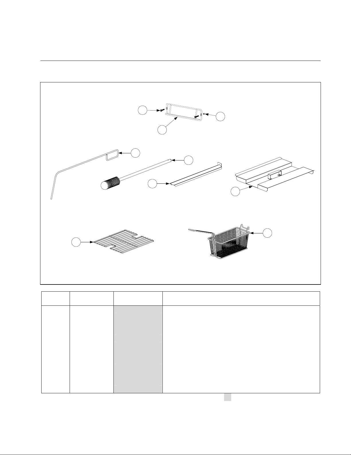
8.1 Accessories
CHAPTER 8: PARTS LIST
1
3
2
4
5
6
7
9
8
ITEM
STANDARD
PART #
**EURO-LOOK
PART #
COMPONENT
1 809-0171 Thumbscrew, ¼ -20 X 13/8-inch
2 810-2793 Hanger, Wireform Basket
3 809-0921 Spacer, Basket Hanger
4 803-0197 Cleanout Rod, 27-inch
5 803-0209 Brush, Frypot
6 823-1885 Connecting Strip, Frypot
7 806-4041 Cover, Full-Vat Frypot
8 803-0132 Rack, Full-Vat Basket Support
9 803-0271 Basket, Twin
* 812-1226SP Drain Nipple 1¼-inch Painted
* 803-0002 Powder, Filter (80 1-Cup Applications)
* 803-0170 Paper, Filter (100-Sheet Pack)
* Not illustrated. Use standard part.
** Euro-Look fryers have rounded topcaps and round drains whereas, standard fryers have square
drains and topcaps.
8-1
Page 2
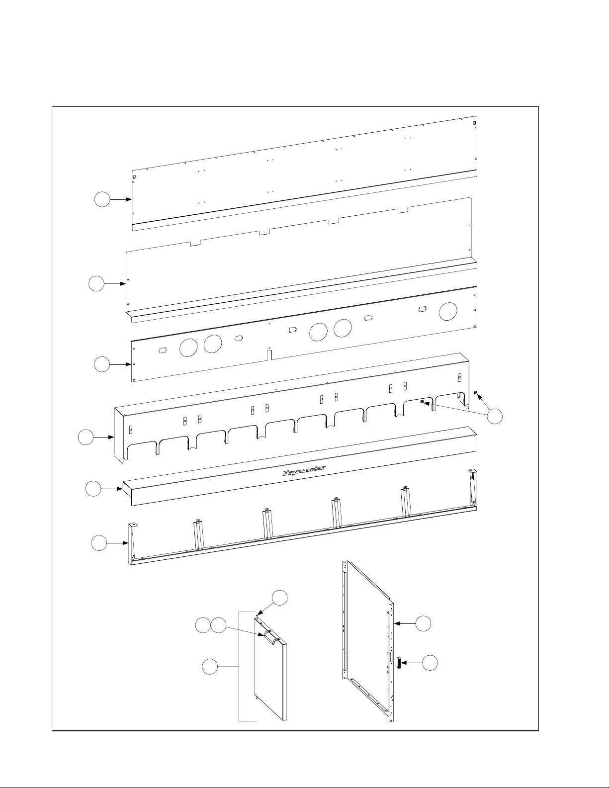
8.2 Cabinetry
8.2.1 Backs, Control Panels, Doors, Handles, Sides, Tilt Housings & Top Caps
1
2
3
5
4
6
7
11
109
12
8
13
8-2
Page 3

8.2.1 Backs, Control Panels, Doors, Handles, Sides, Tilt Housings & Top Caps (cont.)
ITEM
STANDARD
PART #
EURO-LOOK
PART #
COMPONENT
1 210-9367 Back Panel, Upper (Single)
210-2299 200-6630 Two Station Fryer
210-2380 200-6785 Three Station Fryer
210-3490 200-6786 Four Station Fryer
210-3670 200-6787 Five Station Fryer (Panel for five station fryer shown)
2 210-9336 Back Panel, Center (Single)
210-2298 200-2298 Two Station Fryer
210-2379 200-2379 Three Station Fryer
210-3489 200-3489 Four Station Fryer
210-3669 200-3669 Five Station Fryer (Panel for five station fryer shown)
3 210-9339 Back Panel, Lower (Single)
210-4430 200-4426 Two Station Fryer
210-4431 200-4427 Three Station Fryer
210-4432 200-4428 Four Station Fryer
210-4433 200-4429 Five Station Fryer (Panel for five station fryer shown)
4 824-1526 Tilt Housing (Single)
824-1061 824-1303 Two Station
824-1062 824-1335 Three Station
824-1063 824-1336 Four Station
824-1065 824-1337 Five Station (Housing for five station fryer shown)
5 826-1351 826-1351 Nut Retainer, ¼-20 (Pkg. of 10 – receives basket hanger thumbscrew)
6 106-5205 106-5195 Top Cap (Single) (Top cap for five station fryer shown)
106-5206 106-5196 Two Station
106-5207 106-5197 Three Station
106-3036SP 106-5198 Four Station
106-4441 106-5199 Five Station (Also requires ten 809-0078 10-32 Nutserts)
7 106-4956 Frame, Control Panel (Frame for five station fryer shown)
806-7172SP 106-4378 Two Station Fryer
806-7173SP 106-4391 Three Station Fryer
806-7174SP 106-4392 Four Station Fryer
106-2171SP 106-4393 Five Station Fryer
8 806-6545SP 106-4397 Door, Left or Right (Left shown – move handle to opposite side for Right)
9 809-0266 Screw, #10 X ½-inch Phillips Truss Head
10 810-1422 210-6816 Handle, Wireform Door
11 806-4487SP Pin Assembly, Door
* 826-1343 Spring, Door Pin (Pkg. of 10)
* 106-5008 106-4979 Door Assembly (Single)
12 210-4435 Side, Standard Cabinet Left or Right
* 211-8479 Side, Cabinet Single Left (Use 212-8479 for Rt. Side)
13 810-2346 810-1105 Magnet, Door
Handle (Grab Rail) (For handle end use 910-0915)
* 823-0839 823-0839 One Station Fryer
* 823-2908 823-2908 Two Station Fryer
* 823-2901 823-4585 Three Station Fryer
* Not illustrated. Use standard part.
8-3
Page 4
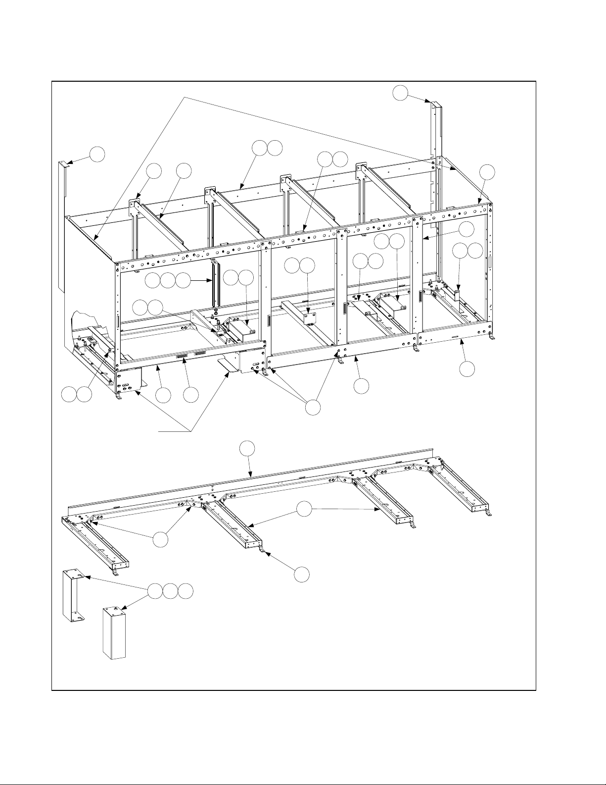
8.2.2 Cabinet Bases, Braces, and Associated Parts
See Page 8-2 for cabinet sides.
See Page 8-24 for rear br idge
support/oil return manifold.
2
1
2415
See Page 8-14 for filter rails
and associated hardware.
8 25
21 23
20
2414
4
2410
2412
282218
17
3
2410
26
30
11 24
6
7
16
9 24
5
29
27 28 32
31
19
The 5-Station cabinet illustrated is typical of all
Navy Surface Ship Electric cabinets. All
components used in Navy Surface Ship cabinets
are identified, but not all comp onents are used in
every configuration.
8-4
Page 5

8.2.2 Cabinet Bases, Braces, and Associated Parts (cont.)
ITEM
STANDARD
PART #
EURO-LOOK
PART #
COMPONENT
1 106-1265 Upright Assembly, Left (Use 106-3828 for singles)
2 106-1266 Upright Assembly, Right (Use 106-3829 for singles)
3 200-1651 Support, Cross Cabinet
4 200-1659 Divider, Cabinet
5 200-2293 Brace, Single Station Lower
6 200-3774 Brace, Double Station Lower
7 Brace, Front Horizontal (Use 200-7036 for singles)
200-2331 Two-Station Fryer
200-2296 Three-Station Fryer
200-2733 Four-Station Fryer
200-3590 Five-Station Fryer
8 Brace, Rear Horizontal (Use 200-5356 for singles)
200-2284 Two-Station Fryer
200-2295 Three-Station Fryer
200-2725 Four-Station Fryer
200-3592 Five-Station Fryer
9 200-4422 Support, Contactor Box Right Station 3 or Station 5
10 201-4425 Support, Contactor Box Left Station 4 or Station 5
11 202-4425 Support, Contactor Box Right Station 3
12 200-4423 Support, Contactor Box Stations 3 and 4
13 200-4447 Support, Contactor Box Front to Rear
14 201-5369 Support, Contactor Box Station 2
15 202-5369 Support, Contactor Box Station 1
* 200-6498 Support, Contactor Box (Singles)
16 200-4424 Post, Door
17 810-2346 Magnet, Door
18 200-4786 Support, Oil Return Manifold
19 210-5595 Hinge, Door (Use 210-6862 for singles)
20 210-1490 Bracket, Rear Support
21 900-1224 Bracket, Frypot
22 826-1389 Bolt, ¼-20 X ¾-inch Hex Head (Pkg. of 10)
23 826-1371 Screw, #8 X ½-inch Drill Point Hex Head (Pkg. of 25)
24 826-1330 Screw, 10-32 X ⅜-inch Slotted (Pkg. of 25, used to attach contactor box)
25 826-1376 Nut, 10-32 Keps Hex (Pkg. of 10)
26 826-1374 Screw, #10 X ½-inch Hex Washer Head (Primary cabinet screw) Qty 25
27 809-0417 Nut, ¼-20 Hex Flange (used with item #22)
28 809-0429 Bolt, ¼-20 X 2-inch Hex Head
29 200-5417 Brace, Rear Channel Corner
30 Channel, Base Rear (Use 106-4901 for singles base assembly)
200-5463 Two-Station Fryer
200-5538 Three-Station Fryer
200-5537 Four-Station Fryer
200-5536 Five-Station Fryer
31 824-1131 Channel, Base Side
32 823-4386 Leg, Navy Shipboard (Mounts with Items 27 and 28)
Use Standard part.
8-5
Page 6
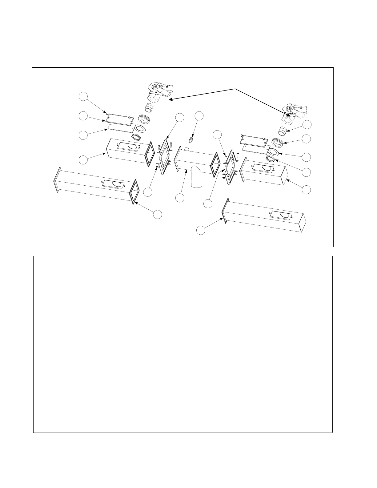
8.3 Drain System Components
8.3.1 Drain Tube Sections and Associated Parts
See Page 8-9 for Drain Valve detail.
5
6
7
10
16
13
14
9
8
15
17
12
ITEM
STANDARD
PART #**
COMPONENT
1 813-0284 Nipple, ¾ X 1-inch NPT
2 816-0092 Grommet, 1-inch Drain
3 826-1345 Washer, 1-inch Drain (Pkg. of 25)
4 809-0347 Nut, 1-inch NPT Retainer
5 809-0893 Nut, 8-32 High Crown Acorn
6 826-1348 Cover, Drain Cleanout (Pkg. of 5)
7 816-0021 Gasket, Drain Cleanout
8 810-2492 Fitting, Quick-Connect Straight (receives Teflon vent tube)
9 823-3229 Drain Outlet
10 823-3380 Drain Tube, Left End
11 823-1549 Drain Tube, Right End Short
12 823-1508 Drain Tube, Right End Long
13 823-0717 Drain Tube, Open End Long
14 810-0396 Clamp, Square Drain
15 826-1375 Screw, 10-32 X ¾-inch Hex Head (Pkg. of 5)
16 826-1376 Nut, 10-32 Keps Hex (Pkg. of 10)
17 816-0032 Gasket, Square Drain
* 826-0877 Kit, Square Drain Clamp (2 each of Items 14-16 and 1 of Item 17)
* 811-1071 Tube, Teflon Vent ¼-inch OD
* Not illustrated.
** See page 8-8 for a Euro-Look parts list.
1
2
3
4
11
8-6
Page 7
8.3.1.1 Euro-Look Drain Tube Section and Associated Parts
1
7
6
2
2
5
8
6
3
3
See Page 8-10 for Drain
Valve Detail
7
1
4
4
8-7
Page 8

8.3.1.1 Euro-Look Drain Tube Section and Associated Parts (cont.)
EURO-LOOK
ITEM
PART# **
COMPONENT
1 Drain Tube, Left/Right End Short
823-4625 Full-Vat 3”
823-4624 Dual-Vat 3”
2 Drain Tube, Left/Right Open Short
823-4643 Full-Vat 3”
823-4642 Dual-Vat 3”
3 Drain Tube, Right End Long
823-4639 Full-Vat 3”
823-4638 Dual-Vat 3”
4 Drain Tube, Left/Right Open Long
823-4641 Full-Vat 3”
823-4640 Dual-Vat 3”
5 823-4892 Drain Outlet Center Dump
6 816-0625 Sleeve 3”
7 809-0969 Clamp, 3” T-Bolt
8 810-2492 Fitting, Quick-Connect Straight (receives Teflon vent tube)
* KIT6033 Kit, Round Drain Clamp (2 or Item 7 and 1 of Item 6)
* 811-1071 Tube, Teflon Vent ¼-inch OD
* Not illustrated.
** See page 8-6 for a standard parts list.
8-8
Page 9
8.3.2 Drain Valve Assembly and Component Parts
Compression Washers
(furnished with Item 1)
Plastic Washer
(furnished with Item 1)
8
7
6
5
4
3
2
1
10
9
Full-Vat Drain Valve
Assembly 806-7434SP
ITEM
STANDARD
PART #**
COMPONENT
1 810-1020 Valve, 1-inch Full-Vat Drain
2 806-8137 Bracket Assembly, Full-Vat Drain Safety Switch
3 816-0220 Insulation, Drain Safety Switch
4 807-2103 Microswitch, CE Straight Lever
5 901-2348 Cover, Dual Vat Drain Safety Switch
6 826-1366 Nut, 4-40 Keps Hex (Pkg. of 25)
7 824-1602 Handle, Full-Vat Drain Valve
8 809-0540 Nut, ½-13 2-Way Hex Lock
9 816-0639 Sleeve, Red Handle
10 900-2936 Retainer, Nut Drain Valve FV
* 806-6993SP Valve, 1 ¼-inch Drain Assembly (Includes handle and sleeve)
* 823-1168 Valve, 1 ¼-inch Drain Assembly with bracket (used on non-filter fryers)
* WIR0572 Wire Bundle, Drain Safety Switch
* Not illustrated.
* See page 8-11 for a Euro-Look parts list.
8-9
Page 10

8.3.2.1 Euro-Look Drain Valves and Associated Parts
(Units with Built-In Filtration)
8-10
Page 11

8.3.2.1 Euro-Look Drain Valves and Associated Parts
(Units with Built-In Filtration) cont.
ITEM
EURO-LOOK
COMPONENT
PART # **
1 809-0539 Nut, ⅜-16 2-Way Hex Lock
2 900-2934 Retainer, Dual-Vat Drain Valve Nut
3 823-5369 Handle, Dual-Vat Drain Valve
4 810-0677 Grip, Drain Handle
5 826-1366 Nut, 4-40 Keps Hex (Pkg. of 25)
6 901-2348 Cover, Dual Vat Drain Safety Switch
7 807-2103 Microswitch, CE Straight Lever
8 816-0220 Insulation, Drain Safety Switch
9 810-1165 Washer, Teflon Drain Valve
10 809-0196 Washer, ⅜-inch Flat
11 106-2671 Bracket Assembly, Dual-Vat Drain Safety Switch
12 810-1114 Valve, 1-inch Dual-Vat Drain
13 809-0540 Nut, ½-13 2-Way Hex Lock
14 824-1602 Handle, Full-Vat Drain Valve
15 816-0639 Sleeve, Red Handle
16 806-8137 Bracket Assembly, Full-Vat Drain Safety Switch
17 810-1018 Valve, 1.25-inch Full-Vat Drain
18 200-6496 Support, 3” Drain
19 900-2936 Retainer, Full-Vat Drain Valve Nut
20 816-0135 Round Drain O-Ring
* WIR0572 Wire Bundle, Drain Safety Switch
* Not illustrated.
** See page 8-9 for a standard parts list.
8-11
Page 12

8.4 Electronics and Wiring Components
8.4.1.1 Single Component Box
ITEM
STANDARD
PART #
EURO-LOOK
PART #
COMPONENT
106-0580 Component Box Assembly Single Navy
1 106-0313 Wire Assembly, Component SFP120
2 806-7179SP Sound Device
3 806-7935 PCB Assembly, Interface
4 806-9559 Component Box W/ Studs
5 807-0012 Relay, 18AMP 1/3 HP 24V Coil
6 807-0065 Block, Terminal
7 807-0069 Circuit Breaker, 10A
8 807-0070 Terminal, Ground Lug
9 807-0855 Transformer, 120V 50/60 – 12V 20A
10 807-1612 Clamp, 3/8 Connector Type (Thin Screw)
11 807-2181 Transformer, Power 100-120V/24V 62VA
12 809-0102 Screw, 8 – 32 x 3/8 TR SL HD ZP
13 809-0104 Screw, 8 – 32 x ½ TR SL HD ZP
14 809-0247 Nut, 8 – 32 Hex KEPS ZP
15 809-0250 Nut, 6 – 32 Hex KEPS ZP
16 809-0349 Spacer, 4mm x 6mm Aluminum
17 809-0360 Screw, 8 x 3/8 Type 8 Hex Washer SL HD ZP
18 826-1374 Screw, #10 – ½ Hex Head (Pkg. of 25)
19 810-0045 Bushing, .875 Dia Hole 11/16
20 810-1164 Block, 1 Plc Screwless Terminal
21 812-0368 Conduit, Flex 3/8”
22 816-0217 Paper, Insulating Terminal Block CE
23 WIR-0428 Wire Assembly, Navy SFP Component
24 WIR-0581 Wire Assembly, Transformer 440V
Use standard part.
8-12
Page 13

8.4.1.2 Multiple Vat Component Boxes
19163
21
20
16
4 12 1516 189 11 16165
10 16
11 16
7
6
162
22
1
COMPONENT
ITEM
STANDARD
PART #
98 13 14 17
NOTE 1: The transformer on the left side of the component
box (Item 11) is present only in the left component box.
NOTE 2: See Page 8-20 for Component Box 15-Pin Wiring
Harnesses.
EURO-LOOK
PART #
106-2458 Assembly, Component Box w/ filter
106-2449 Assembly, Component Box without filter
1 106-1531 Box, Component
2 200-3300 Bracket, Component Box Strain Relief
3 200-3746 Bracket, Circuit Breaker
4 806-9495SP Terminal Block and Wire Assembly
5 807-0012 Relay, 18 Amp ⅓ HP 24V Coil
6 826-1337 Terminal, ¼-inch Push-on (Pkg. of 5)
7 807-0121 Bushing, Heyco Plastic AB-625-500
8 807-1321 Holder, AGC Panel-Mount ¼-inch Fuse
9 807-1597 Fuse, 3 Amp Slow-Blow
10 807-0855 Transformer, 100-120V/24V 20VA
11 807-2181 Transformer, 100-120V/12V 60VA
12 826-1366 Nut, 4-40 Keps Hex (Pkg. of 25)
13 809-0250 Nut, 6-32 Keps Hex
14 809-0349 Spacer, 4mm X 6mm Aluminum
15 826-1359 Screw, 4-40 X ¾-inch Slotted Round Head (Pkg. of 25)
16 809-0359 Screw, #8 X ¼-inch Hex Washer Head
17 806-7935 Interface Board
807-3932 Relay, 12VDC SPDT 12 Amp
18 806-7179SP Sound Device
19 807-0069 Circuit Breaker, 10 Amp
20 200-3844 Guard, Finger
21 810-2445 Plug, Button
22 200-3243 Brace, Component Box
* 106-2400 Handle Assembly, FPP Power Shower FV
*Not illustrated. Use standard part.
8-13
Page 14

8.4.2.1 Single Contactor Box
ITEM
STANDARD
PART #
EURO-LOOK
PART #
COMPONENT
106-0581 Box, Assembly Contactor Single Navy
1 106-0595 Wire Assembly, CI Single FP
2 806-9628SP Wire Assembly, HV DV LT Contactor Single
3 806-9629SP Wire Assembly, HV DV RT Contactor Single
4 807-0012 Relay, 18 AMP 1/3 HP 24V Coil
5 807-0067 Block, Terminal 8 Pin
6 807-0878 Block, Terminal 3 Lug 12 P
7 807-1338 Fitting, Plastic ¾ Dia Conduit
8 807-1683 Relay, 12 VDC
9 809-0096 Screw, 6 – 32 x ⅝ Bindings SL HD ZP
10 809-0102 Screw, 8 – 32 x ⅜ TR HD ZP
11 809-0250 Nut, 6 – 32 KEPS HX ZP
12 809-0266 Screw, 10- ½ Phil TR HD ZP
13 809-0360 Screw, 8 x ⅜ HX Washer SL HD ZP
14 809-0362 Screw, Drill #8 x 1 ¼ Hex Washer HD ZP
15 826-1374 Screw, #10-½ Hex Head (Pkg. of 25)
16 810-0044 .875 Plug Button
17 810-1202 Contactor, 40 AMP 600V 3 Pole
18 812-0971 Conduit, ¾ x 12 LG Flexible
19 900-8608 Box, Contactor Common El. Single FP
20 900-8609 Cover, Contactor Box Common El. Single FP
21 900-8647 Bracket, Contactor Box Single FP
22 WIR0427 Wire Assembly, Navy Single FP
Use standard part.
8-14
Page 15

8.4.2.2 Multiple Vat Contactor Boxes
1
4 17
16155
10 13 14
1898
1896
OR
1897
2
173
11 9 18
12 13 14
NOTE 1: Left and right contactor box assemblies are mirror images of one another. With the
exception of the box itself, all components of a left-hand assembly, including the lid, are the same as
those in the corresponding right-hand assembly and vice versa.
NOTE 2: See Page 8-18 and 8-19 for Contactor Box Wiring Assembly
ITEM
STANDARD
PART #
EURO-LOOK
PART #
COMPONENT
106-2440 Assembly, Contactor Box Left (Use 106-2442 for H22)
106-2441 Assembly, Contactor Box Right (Use 106-2443 for H22)
1 106-1536 Box, Left Contactor
2 106-1537 Box, Right Contactor
3 200-4712 Door, Contactor Box w/o Hinge
4 200-2337 Bracket, Contactor Box
5 807-0070 Terminal, Ground Lug
6 807-2284 Contactor, 24V 50 Amp Mechanical (used in 14 & 17kW units only)
7 807-2283 Contactor, 24V 63 Amp Mechanical (used in 22kW units only)
8 810-1202 Contactor, 24V 40 Amp 3-Pole
9 809-0448 Clip, Tinnerman
10 807-0012 Relay, 18 Amp ⅓ HP 24V Coil
11 807-0064 Transformer, 480V/120V 150VA
12 807-1683 Relay, 12VDC
13 826-1358 Nut, 6-32 Keps Hex (Pkg. of 25)
14 826-1365 Screw, 6-32 X ⅜-inch Slot Head (Pkg. of 25)
15 809-0123 Screw, #10 X ¾-inch Slot Head
16 826-1376 Nut, 10-32 Keps Hex (Pkg. of 10)
17 809-0360 Screw, #8 X ⅜-inch Hex Washer Slot Head
18 826-1374 Screw, #10 X ½-inch Hex Head (Pkg. of 25)
* 200-5627 Lid, Left or Right Contactor Box
* 807-2240 Fuse, 60 AMP 300VAC (replaced 45 AMP)
* 807-0501 Fuseholder block
** Not illustrated. Use standard part.
8-15
Page 16

8.4.3 Heating Element Assembly and Associated Parts
3
4
9
7
6
8
10
20
5
11
1
1
2
1312
15
1413
16
17
18
19
22
NOTES:
The only difference between element assem blies for different voltage and kW ratings is the element it self (Item 1)
Items 21 and 22 are shown as assoc i at ed parts. They are not part of the element assembly.
21
8-16
Page 17

8.4.3 Heating Element Assembly and Associated Parts (cont.)
ITEM
STANDARD
PART #
EURO-LOOK
PART #
COMPONENT
1 Element
807-2649 440V 17.0 kW
807-2650 440V 18.5 kW
807-3176 440V 11.0 kW
807-2651 480V 17.0 kW
807-2652 480V 18.5 kW
807-3177 480V 11.0 kW
2 826-1526 Probe, Temperature
3 106-0004SP Tilt Plate Assembly
4 106-0572SP Bracket, Left Spring Slot
5 106-0573SP Bracket, Right Spring Slot
6 910-9641 Tilt Plate
7 810-0035 Hinge
8 826-1330 Screw, 10-32 X ⅜-inch Slotted Truss Head (Pkg. of 25)
9 826-1376 Nut, 10-32 Keps Hex (Pkg. of 10)
10 826-1339 Bushing, .375-inch Split (Pkg. of 10)
11 816-0480 Plug, .375-inch Dome
12 910-5022 Bracket, Temperature Probe
13 809-0518 Screw, 8-32 X ⅜-inch Slotted Hex Head
14 910-2042 Clamp, Element (Short)
15 910-5213 Clamp, Element (Long)
16 910-3681 Support, Full-Vat Element Rear
17 823-2377 Support, Full-Vat Element Front
18 810-1233 Handle, Element Lift
19 810-1212 Pin, .125 X .5-inch Split
20 809-0567 Tie-Wrap, Metal
21 200-2060 Bracket, Lower Spring Slot
22 810-0297 Spring, Element
Use standard part.
8-17
Page 18
8.4.4 Controller
Controller P/N 806-3798
Knob P/N 810-0387
Toggle Switch P/N 807-3308
8.4.5 Wiring
8.4.5.1 Contactor Box Wiring Assembly – 12-Pin Full-Vat C-1
1
2
3
4
5
6
7
8
9
10
11
12
BLACK
GREEN/YELLOW
WHITE
BROWN
WHITE
BLACK
RED
ORANGE
BLACK
YELLOW
P/N 106-2477SP
8.4.5.2 Contactor Box Wiring Assemblies – 6-Pin (Left Element)
1
2
3
4
5
6
BLUE
BLUE
BLUE
BLACK
BLACK
BLACK
P/N 106-3468SP 14/17kW or P/N 106-2473SP 22kW
8-18
Page 19

8.4.5.3 Contactor Box Wiring Assemblies – 9-Pin (Right Element)
1
2
3
4
5
6
7
8
9
BLUE
BLUE
BLUE
BLACK
BLACK
BLACK
P/N 106-3467SP 14/17kW or P/N 106-2472SP 22kW
8.4.5.4 Single Contactor Box Wiring Assembly
8.4.5.5 Main Wiring Harness
15-Pin Male Connector
807-0804 (Rear of Fryer)
C6
1
12-Pin Male Connector
807-0160 (Contactor Box)
12-Pin Male Connector
807-0160 (Interface Board)
J1
J4
J5
J6
4-Pin Female Connector
C1
P/N 807-3769
807-3232 (Drain Safety Switches)
J2
15-Pin Male Connector
807-0804 (Component Box)
6-Pin Male Connector
807-0157 (Not used in Navy units)
12-Pin Male Connector
807-0160 (Interface Board)
8-19
Page 20

8.4.5.6 Single Main Wiring Harness
8.4.5.7 Component Box Wiring Harness – 15-Pin
P/N 106-2506SP
8.4.5.8 Single Component Box Wiring Harness – 15-Pin
8.4.5.9 Single Component Box Wiring Harness – 15-Pin without Filter
8.4.5.10 Interface Board to Controller Wiring Harness – 15-Pin
P/N 806-2071
8-20
Page 21
8.5 Filtration System Components
8.5.1 FPH117/122 Filtration Components
8-21
Page 22

8.5.1 FPH117/122 Filtration Components (cont.)
ITEM PART # EURO-LOOK
COMPONENT
PART#
806-9546SP 106-4945 Assembly, Filter Pan FPH117
1 806-9547 Lid, Single FPH117
2 810-2743 Crumb Tray
3 823-2899 Hold Down Ring
4 900-8933 SanaGrid Filter Screen
5 823-2828 823-5141 Pan, Filter
6 826-1360 Screw, 10-24 x 5/16 RD SL HD ZP (Pkg. of 25)
7 826-1376 Nut, KEPS, 10 – 32 HX ZP (Pkg. of 10)
8 810-0180 Handle, Door
9 810-2805 Caster, 2” Filter Pan
10 810-2807 Caster, 2” Rigid
11 813-0568 Pipe Plug 1/8 NPT Socket Head
12 823-5142 Tube, Pan Suction Single FP
106-4976 Plumbing Assembly, FV Single FP
13 826-1712 Kit, Motor and Gasket 115V (807-3859 Motor)
14 810-2944 Gemini Valve without Handle
15 810-1057 Flex Line 5/8” O.D. x 13” Long
16 810-1067 Flex Line 5/8” O.D. x 8.5” Long
17 810-1668 Adapter, Male 7/8” O.D. x ½”
18 813-0022 Nipple, ½” x Close N.P.T. B.M.
19 813-0098 Nipple, ½” x 6.50” N.P.T. B.M. Pipe
20 813-0616
Elbow, ST ½” x ½” NPT 90° BM
21 813-0331 Elbow, W/Side Outlet – ½” NPT
22 813-0469 Cap, Pipe ½” BM
23 210-9197 Handle, Right RF Valve
24 826-1264 Kit, Pump and Gasket, Viking 4 GPM 2-piece
25 816-0093 Gasket, Pump / Motor
26 809-0514 Cap Screw, 5/16” – 18 NC SAE Grade 5, HX HD
27 809-0194 Washer, Flat 5/16” SAE ZP
106-4951 Rail Assembly, Filter Pan Single FPH117
28 809-0500 Screw, 10 – ½” HX HD SS
29 210-9145 Angle, Joining, Pan Rails Filter Magic
30 211-9147 Leg, Pan Rail FM Left
31 211-9146 Bracket, Attaching Filter Pan Left
32 212-9147 Leg, Pan Rail FM Right
33 212-9146 Bracket, Attaching Filter Pan Right
34 211-9455 Rail, Filter Pan Left
35 212-9455 Rail, Filter Pan Right
36 823-5151 Mount W/A, Male Connector
37 810-0697 Disconnect, Filter Pan Connection (Male)
38 826-1392 O-Ring, Filter Pan Connection (Pkg. of 5)
Use standard part.
8-22
Page 23

8.5.2 FPH217/317 Multiple Battery Filtration System Components
NOTE: Some early production
1
units were confi gur e d this way.
37
38
24
29
2
3
4
19
17
25
16
30
28
12119
14
8
20
121110
18
36
35
34
25
18
22
24
23
21
8
27
26
32
33
31
6
5
13
7
15
8-23
Page 24

8.5.2 FPH217/317 Multiple Battery Filtration System Components (cont.)
ITEM
STANDARD
PART #
* 826-1979 Filter Pan Roller Kit (four each of Items 7 and 8)
* 826-1980 Service Filter Pan (Item 5 minus Item 2)
* 826-1981 Service Filter Pan Assembly (Service Filter Pan above plus Items 3 & 4)
* 826-1392 O-Ring (Pkg. of 5; used with Item 5)
* 813-0568 Plug, ⅛-inch Socket Head Pipe (component of Item 5; two required)
* 811-1071 Tubing, ¼-inch OD Teflon Vent (sold by the foot)
* 806-5933SP Heater Strip Assembly, 120V 18” 25W
1 823-4637 823-4787 Lid (for units built before Feb 04, use 823-4391)
2 810-2743 Crumb Tray (component of Item 5)
3 810-2091 Hold Down Ring
4 200-2124 SanaGrid Filter Screen
5 106-2617SP Pan, One-Piece Filter (includes Item 2 and o-rings)
6 810-2012 Rail Set, Filter Pan Roller (includes one left and one right)
7 810-2198 Roller, Filter Pan and Rail
8 826-1372 Nut, ¼-20 Hex (Pkg. of 10)
9 823-4589 823-4675 Bracket, Lid Support (for units built before Feb 04, use 823-3875)
10 200-3556 Guide, Filter Pan Lid
11 809-0104 809-0503 Screw, 8-32 X ½-inch Slotted Truss Head
12 809-0247 Nut, 8-32 Hex Keps
13 823-3879 Suction Tube
14 200-4408 Rail, Left Filter
15 200-4409 Rail, Right Filter
16 826-1712 Kit, Motor and Gasket 115V 60Hz (807-3859 Motor)
17 826-1264 Pump and Gasket Kit
18 807-2484 Valve, ¼-inch Solenoid
19 813-0165 Elbow, ½-inch 90° Street
20 813-0342 Elbow, ½-inch 45° Street
21 813-0530 Tee, ½-inch X ¼-inch X ½-inch Reducing
22 813-0022 Nipple, ½-inch Close
23 813-0838 Nipple, ¼-inch Close
24 813-0304 Bushing, ½-inch to ¼-inch Flush
25 810-1668 Adapter, ⅝-inch to ½-inch NPT Male
26 810-1669 Adapter, ⅝-inch to ½-inch NPT Female
27 810-1159 Flexline, 5.0-inch Oil Return
28 810-1369 Flexline, 17.5-inch Oil Return
29 810-1055 Flexline, 11.5-inch Oil Return
30 807-3828 Cable, FootPrint Pro Pump Motor
31 826-1375 Screw, 10-32 X ¾-inch Hex Trim Head (Pkg. of 5)
32 200-5950 Bridge, Filter Motor
33 210-3149 Support, Contactor Box
34 813-0003 Tee, ½-Inch
35 813-0298 Nipple, ½-inch 2.0-inch
36 813-0537 Nipple, ¼-inch 2.0-inch
37 810-2493 Fitting, ¼-inch X 90° Quick-Connect
38 810-1160 Flexline, 3.0-inch Oil Return
* 810-1043 Flexline, 9.5-inch Oil Return
* 810-1057 Flexline, 13.0-inch Oil Return
* Not illustrated. Use standard part.
EURO-LOOK
PART #
COMPONENT
8-24
Page 25

8.6 Frypot Assembly and Thermostat
Frypot P/N 823-2451SP Thermostat P/N 806-7543
8-25
Page 26

8.7 Oil Return System Components
23
22
21
18
17
20
19
5
11
13
9
12
6
10
8
3
16
15
7
14
4
2
8-26
1
Page 27

8.7 Oil Return System Components (cont.)
ITEM
STANDARD
PART #
EURO-LOOK
PART #
COMPONENT
1 806-4505SP Power Shower Assembly, Full-Vat
2 826-0992 Seal, Power Shower (Pkg. of 3)
3 809-0415 Screw, Power Shower Cleanout
4 814-0001 Grip, Power Shower Handle
5 807-2103 Microswitch, Oil Return
6 810-2330 Handle, Oil Return Valve
7 809-0601 Clip, Clevis
8 810-0677 Grip, Oil Return Valve Handle
9 200-5401 Bracket, Handle Retainer
10 106-3349 Bracket, Oil Return Microswitch
11 816-0220 Insulation, Oil Return Microswitch
12 826-1359 Screw, 4-40 X ¾-inch Slotted Pan Head (Pkg. of 25)
13 826-1366 Nut, 4-40 Keps Hex (Pkg. of 25)
14 813-0165 Elbow, ½-inch X 90° Street
15 810-0278 Valve, ½-inch Ball
16 810-1668 Adapter, ⅝-inch to ½-inch NPT Male
17 810-1680 Flexline, 6.5-inch
18 810-1669 Adapter, ⅝-inch to ½-inch NPT Female
19 813-0469 Cap, ½-inch NPT Pipe
20 810-2255 Manifold, Two-Station Fryer
21 810-2256 Manifold, Three-Station Fryer
22 810-2257 Manifold, Four-Station Fryer
23 810-2312 Manifold, Five-Station Fryer
Use standard part.
8-27
Page 28

8.8 WIRING CONNECTORS, PIN TERMINALS, AND POWER CORDS
1 2
6
11
7 9 10
3
8
12
4
13
ITEM
STANDARD
PART #
* 807-3834
*
1 807-1068
2 807-0158
3 807-0156
5 807-0159
5 807-0875
6 807-1067
7 807-0157
8 807-0155
9 807-0160
10 807-0804
11 826-1341
12 826-1342
13 807-2518
* Not illustrated. Use standard part.
EURO-LOOK
PART #
Power Cords
Cable, 3-Phase 4-Wire (Fryer Power Cable)
Cord, Filter System Power
Connectors
2-Pin Female
6-Pin Female
9-Pin Female
12-Pin Female
15-Pin Female
2-Pin Male
6-Pin Male
9-Pin Male
12-Pin Male
15-Pin Male
Terminal, Female Split Pin
Terminal, Male Split Pin
Plug, Mate-N-Lock (Dummy Pin)
COMPONENT
(Pkg of 25)
(Pkg of 25)
5
8-28
 Loading...