

Page 1
Installation, Operation, Service and Parts Manual
PRO SERIES MARINE ELECTRIC
FRYERS
Frymaster, a member of the Commercial Food Equipment Service Association, recommends
using CFESA Certified Technicians.
www.frymaster.com Email: service@frymaster.com
24-Hour Service Hotline 1-800-551-8633
*8196118*
JULY 2005
PDF compression, OCR, web optimization using a watermarked evaluation copy of CVISION PDFCompressor
Page 2
NOTICE
IF, DURING THE WARRANTY PERIOD, THE CUSTOMER USES A PART FOR THIS ENODIS
EQUIPMENT OTHER THAN AN UNMODIFIED NEW OR RECYCLED PART PURCHASED
DIRECTLY FROM FRYMASTER/DEAN, OR ANY OF ITS AUTHORIZED SERVICE CENTERS,
AND/OR THE PART BEING USED IS MODIFIED FROM ITS ORIGINAL CONFIGURATION, THIS
WARRANTY WILL BE VOID. FURTHER, FRYMASTER/DEAN AND ITS AFFILIAT ES WILL NOT BE
LIABLE FOR ANY CLAIMS, DAMAGES OR EXPENSES INCURRED BY THE CUSTOMER WHICH
ARISE DIRECTLY OR INDIRECTLY, IN WHOLE OR IN PART, DUE TO THE INSTALLATION OF
ANY MODIFIED PART AND/OR PART RECEIVED FROM AN UNAUTHORIZED SERVICE CENTER.
DANGER
Copper wire suitable for at least 167°F (75°C) must be used for power connections.
DANGER
The electrical power supply for this appliance must be the same as indicated on the rating and
serial number plate located on the inside of the fryer door.
DANGER
This appliance must be connected to the voltage and phase as specified on the rating and serial
number plate located on the inside of the fryer door.
DANGER
All wiring connections for this appliance must be made in accordance with the wiring diagrams
furnished with the equipment. Wiring diagrams are located on the inside of the fryer door.
DANGER
Do not store or use gasoline or other flammable vapors and liquids in the vicinity of this or any
other appliance.
NOTICE
Drawings and photos used in this manual are intended to illustrate operational, cleaning and
technical procedures. They may differ slightly in appearance or placement between fryers but
functionality should remain the same. They may not conform to onsite management operational
procedures.
WARNING
Frymaster fryers equipped with legs are for permanent installations. Fryers fitted with legs
must be lifted during movement to avoid damage and possible bodily injury. For a moveable or
portable installation, Frymaster optional equipment casters must be used.
Questions? Call 1-800-551-8633 or email Service @Frymaster.com
DANGER
The front ledge of the fryer is not a step. Do not stand on the fryer. Serious injury can result
from slips or contact with the hot oil.
DANGER
All wiring connections for this appliance must be made in accordance with the wiring diagrams
furnished with the equipment. Wiring diagrams are located on the inside of the fryer door.
WARNING
This equipment is intended for indoor use only. Do not install or operate this equipment in
outdoor areas.
PDF compression, OCR, web optimization using a watermarked evaluation copy of CVISION PDFCompressor
Page 3
NOTICE
This appliance is intended for professional use only and is to be operated by qualified
personnel only. A Frymaster/DEAN Factory Authorized Service Center (FASC) or other qualified
professional should perform installation, maintenance, and repairs. Installation, maintenance,
or repairs by unqualified personnel may void the manufacturer’s warranty.
NOTICE
This equipment must be installed in accordance with the appropriate national and local codes of
the country and/or region in which the appliance is installed.
NOTICE TO U.S. CUSTOMERS
This equipment is to be installed in compliance with the basic plumbing code of the Building
Officials and Code Administrators International, Inc. (BOCA) and the Food Service Sanitation
Manual of the U.S. Food and Drug Administration.
WARNING
No structural material on the fryer should be altered or removed to accommodate placement of
the fryer under a hood. Questions? Call the Frymaster Dean Service Hotline at 1-800-551-8633.
NOTICE TO OWNERS OF UNITS EQUIPPED WITH COMPUTERS
U.S.
This device complies with Part 15 of the FCC rules. Operation is subject to the following two
conditions: 1) This device may not cause harmful interference, and 2) This device must accept
any interference received, including interference that may cause undesired operation. While
this device is a verified Class A device, it has been shown to meet the Class B limits.
CANADA
This digital apparatus does not exceed the Class A or B limits for radio noise emissions as set
out by the ICES-003 standard of the Canadian Department of Communications.
Cet appareil numerique n’emet pas de bruits radioelectriques depassany les limites de classe A
et B prescrites dans la norme NMB-003 edictee par le Ministre des Communcations du Canada.
DANGER
Improper installation, adjustment, maintenance or service, and unauthorized alterations or
modifications can cause property damage, injury, or death. Read the installation, operating,
and service instructions thoroughly before installing or servicing this equipment.
DANGER
The crumb tray in fryers equipped with a filter system must be emptied into a fireproof container
at the end of frying operations each day. Some food particles can spontaneously combust if left
soaking in certain shortening material.
WARNING
Do not bang fry baskets or other utensils on the fryer’s joiner strip. The strip is present to seal
the joint between the frypots. Banging fry baskets on the strip to dislodge shortening will
distort the strip, adversely affecting its fit. It is designed for a tight fit and should only be
removed for cleaning.
WARNING
Never spray the fryer with water or use water jets to clean the fryer.
PDF compression, OCR, web optimization using a watermarked evaluation copy of CVISION PDFCompressor
Page 4

Pro Series Marine Electric Fryers
Installation, Operation, Service and Parts Manual
TABLE OF CONTENTS
CHAPTER 1: Introduction
1.1 General ..............................................................................................................................1-1
1.2 Safety Information............................................................................................................. 1-1
1.3 Controller Information ......................................................................................................1-2
1.4 Shipping Damage Claim Procedure..................................................................................1-2
1.5 Service Information........................................................................................................... 1-2
CHAPTER 2: Installation Instructions
2.1 Introduction....................................................................................................................... 2-1
2.2 Power Requirements..........................................................................................................2-2
2.3 Installation.........................................................................................................................2-3
2.4 After the Fryers are Anchored at the Frying Station.........................................................2-3
2.5 Dimensions and Weights...................................................................................................2-4
CHAPTER 3: Operating Instructions
3.1 Equipment Setup and Shutdown Procedures.....................................................................3-1
3.2 Operation of the Solid-State Digital Controller ................................................................3-2
CHAPTER 4: Filtration Instructions
4.1 Introduction....................................................................................................................... 4-1
4.2 Preparing the Filter for Use...............................................................................................4-1
4.3 Operation of the Filter.......................................................................................................4-3
4.4 Draining and Disposing of Waste Oil ...............................................................................4-4
CHAPTER 5: Preventive Maintenance
5.1 Cleaning the Fryer.............................................................................................................5-1
5.1.1 Clean Inside and Outside of the Fryer Cabinet ..................................................5-1
5.1.2 Clean the Built in Filtration System...................................................................5-1
5.1.3 Clean the Frypot and Heating Elements (Boil-Out)........................................... 5-2
5.1.4 Clean Detachable Parts and Accessories............................................................5-3
5.2 Annual/Periodic System Inspection ..................................................................................5-3
i
PDF compression, OCR, web optimization using a watermarked evaluation copy of CVISION PDFCompressor
Page 5

CHAPTER 6: Operator Troubleshooting
6.1 Introduction....................................................................................................................... 6-1
6.2 Troubleshooting.................................................................................................................6-2
6.2.1 Control and Heating Problems........................................................................... 6-2
6.2.2 Filtration Problems.............................................................................................6-4
CHAPTER 7: Service Procedures
7.1 General ..............................................................................................................................7-1
7.2 Replacing a Remote Digital Controller.............................................................................7-1
7.3 Replacing Component Box Components.......................................................................... 7-1
7.4 Replacing a Temperature Probe or High-Limit Thermostat .............................................7-2
7.5 Replacing a Heating Element............................................................................................7-4
7.6 Replacing Contactor Box Components.............................................................................7-5
7.7 Replacing a Frypot ............................................................................................................7-6
7.8 Built in Filtration System Service Procedures .................................................................. 7-8
7.8.1 Filtration System Problem Resolution ...............................................................7-8
7.8.2 Replacing the Filter Motor, Filter Pump and Related Components...................7-9
7.8.3 Replacing the Filter Transformer or Filter Relay............................................. 7-11
7.9 Interface Board Diagnostic Chart....................................................................................7-12
7.10 Wiring Diagram, Simplified H17.................................................................................... 7-13
7.11 Wiring Diagram, System................................................................................................. 7-14
7.11.1 FP117 Single ....................................................................................................7-14
7.11.2 FPPH217 .......................................................................................................... 7-15
7.12 Wiring Diagram, Contactor Box..................................................................................... 7-16
7.12.1 FP117 Single ....................................................................................................7-16
7.12.2 FPPH217 .......................................................................................................... 7-17
7.13 Wiring Diagram, Filter Box FP117 Single...................................................................... 7-18
7.14 Wiring Diagram, Wiring Harnesses................................................................................7-19
7.14.1 FP117 Single ....................................................................................................7-19
7.14.2 FPPH17 ............................................................................................................ 7-20
7.15 Wiring Diagram, Remote Cable...................................................................................... 7-21
CHAPTER 8: Parts List
8.1 Accessories........................................................................................................................ 8-1
8.2 Cabinetry........................................................................................................................... 8-2
8.2.1 FPPH217 Backs, Panels, Doors, Handles, Sides, Tilt House & Topcap............8-2
8.2.2 Cabinet Bases, Braces and Associated Parts......................................................8-4
8.2.2.1 FPH117 Single ..................................................................................... 8-4
8.2.2.2 FPPH217 Double..................................................................................8-6
8.3 Drain System Components................................................................................................ 8-8
8.3.1 FPPH217 Euro-Look Drain Tube Sections and Parts........................................8-8
8.3.2 Drain Valve Assembly and Component Parts.................................................... 8-9
8.3.2.1 FPH117 Single Drain Valve Assembly............................................... 8-9
8.3.2.2 FPPH217 Euro-Look Drain Valve Assembly................................... 8-10
ii
PDF compression, OCR, web optimization using a watermarked evaluation copy of CVISION PDFCompressor
Page 6

8.4 Electronics and Wiring Components............................................................................... 8-11
8.4.1 Component Boxes ............................................................................................8-11
8.4.1.1 FPH117 Single Component Box.......................................................8-11
8.4.1.2 FPPH217 Component Box................................................................ 8-13
8.4.2 Contactor Boxes............................................................................................... 8-15
8.4.2.1 FPH117 Single Contactor Box..........................................................8-15
8.4.2.2 FPPH217 Contactor Box...................................................................8-17
8.4.3 Heating Element Assembly and Associated Parts............................................ 8-18
8.4.4 Remote Digital Controller................................................................................8-20
8.4.5 Wiring Assemblies and Harnesses................................................................... 8-20
8.4.5.1 FPPH217 Contactor Box Wiring Assembly 12-Pin.......................... 8-20
8.4.5.2 FPPH217 Contactor Box Wiring Assembly 6-Pin............................ 8-20
8.4.5.3 FPPH217 Contactor Box Wiring Assembly 9-Pin............................ 8-21
8.4.5.4 FPH117 Single Contactor Box Wiring Assembly............................. 8-21
8.4.5.5 FPPH217 Main Wiring Harness........................................................8-21
8.4.5.6 FPH117 Single Main Wiring Harness...............................................8-22
8.4.5.7 FPPH217 Component Box Wiring Harness...................................... 8-22
8.4.5.8 FPH117 Single Component Box Wiring Harness............................. 8-22
8.5 Filtration System Components........................................................................................8-23
8.5.1 FPH117 Single Filtration Components ............................................................8-23
8.5.2 FPPH217 Filtration Components .....................................................................8-25
8.6 Frypot Assembly and Thermostat ...................................................................................8-27
8.7 FPPH217 Oil Return System Components ..................................................................... 8-27
8.8 Wiring Connectors, Pin Terminals, Seals and Power Cords........................................... 8-29
iii
PDF compression, OCR, web optimization using a watermarked evaluation copy of CVISION PDFCompressor
Page 7
PRO SERIES MARINE ELECTRIC FRYERS
CHAPTER 1: INTRODUCTION
1.1 General
Read the instructions in this manual thoroughly before attempting to operate this equipment. This
manual covers all configurations of Pro Series Electric Fryer models specifically configured for use
aboard surface ships, including FPH17 kW and FPPH17 kW models. The fryers in this model family
have most parts in common, and when discussed as a group, will be referred to as “Pro Series
Marine Electric” fryers.
The Pro Series Marine Electric fryers feature a built-in filtration system and also include features
such as deep cold-zones and open frypots with tilt-up elements. These fryers are equipped with
remote mounted solid-state digital controllers. Fryers in this series can be single units or grouped in
batteries of two or more fryers.
1.2 Safety Information
Before attempting to operate your unit, read the instructions in this manual thoroughly.
Throughout this manual, you will find notations enclosed in double-bordered boxes similar to the
one below.
DANGER
Hot cooking oil causes severe burns. Never attempt to move a fryer containing hot
oil or to transfer hot oil from one container to another.
CAUTION boxes contain information about actions or conditions that may cause or result in a
malfunction of your system.
WARNING boxes contain information about actions or conditions that may cause or result in
damage to your system, and which may cause your system to malfunction.
DANGER boxes contain information about actions or conditions that may cause or result in
injury to personnel, and which may cause damage to your system and/or cause your system to
malfunction.
Fryers in this series are equipped with the following automatic safety features:
1. Two high-temperature detection features one of which sounds an alarm and the other shuts off
power to the elements should the temperature control fail and the temperature continue to rise.
2. A safety switch built into the drain valve, which prevents the elements from heating with the
drain valve even partially open.
3. A magnetic tilt switch that shuts off the elements when lifted for frypot cleaning.
PDF compression, OCR, web optimization using a watermarked evaluation copy of CVISION PDFCompressor
1-1
Page 8

1.3 Controller Information
This equipment has been tested and found to comply with the limits for a Class A digital device,
pursuant to Part 15 of the FCC rules. While this device is a verified Class A device, it has been
shown to meet the Class B limits. These limits are designed to provide reasonable protection against
harmful interference when the equipment is operated in a commercial environment. This equipment
generates, uses and can radiate radio frequency energy and, if not installed and used in accordance
with the instruction manual, may cause harmful interference to radio communications.
The user may find the following booklet prepared by the Federal Communications Commission
helpful: "How to Identify and Resolve Radio-TV Interference Problems". This booklet is available
from the U.S. Government Printing Office, Washington, DC 20402, Stock No. 004-000-00345-4.
1.4 Shipping Damage Claim Procedure
What to do if this equipment arrives damaged:
Please note that this equipment was carefully inspected and packed by skilled personnel before
leaving the factory. The freight company assumes full responsibility for safe delivery upon
acceptance of the equipment.
1. File Claim for Damages Immediately—Regardless of extent of damage.
2. Visible Loss or Damage—Be sure this is noted on the freight bill or express receipt and is signed
by the person making the delivery.
3. Concealed Loss or Damage—If damage is unnoticed until equipment is unpacked, notify the
freight company or carrier immediately and file a concealed damage claim. This should be done
within 15 days of date of delivery. Be sure to retain container for inspection.
1.5 Service Information
For non-routine maintenance or repairs, or for service information, contact your local Frymaster
Authorized Service Center (FASC). Service information may also be obtained by calling the
Frymaster Technical Services Department at 1-800-551-8633 or via e-mail at
service@frymaster.com. The following information will be needed in order to assist you efficiently:
Model Number:
Serial Number:
Voltage:
Also be prepared to describe the specific problem.
RETAIN AND STORE THIS MANUAL IN A SAFE PLACE FOR FUTURE USE.
PDF compression, OCR, web optimization using a watermarked evaluation copy of CVISION PDFCompressor
1-2
Page 9
PRO SERIES MARINE ELECTRIC FRYERS
CHAPTER 2: INSTALLATION INSTRUCTIONS
2.1 Introduction
The instructions in this chapter cover all configurations of Pro Series Electric Fryer models
specifically configured for use aboard surface ships, including FPH17 kW and FPPH17 kW models.
The instructions do not cover and may not be used for installations ashore.
Proper installation is essential for the safe, efficient, trouble-free operation of this appliance.
Any unauthorized alteration of this equipment will void the Frymaster warranty.
NOTICE
If this equipment is wired directly into the electrical power supply, a means for
disconnection from the supply having a contact separation of at least 3-mm in all
poles must be incorporated in the fixed wiring.
NOTICE
This equipment must be positioned so that the plug is accessible unless other
means for disconnection from the power supply (e.g., a circuit breaker) is provided.
NOTICE
If this appliance is permanently connected to fixed wiring, it must be connected by
means of copper wires having a temperature rating of not less than 167°F (75°C).
NOTICE
If the electrical power supply cord is damaged, it must be replaced by a Frymaster
Dean Factory Authorized Service Center technician or a similarly qualified person in
order to avoid a hazard.
DANGER
This appliance must be connected to a power supply having the same voltage and
phase as specified on the rating plate located on the inside of the appliance door.
DANGER
All wiring connections for this appliance must be made in accordance with the
wiring diagram(s) furnished with the appliance. Refer to the wiring diagram(s)
affixed to the inside of the appliance door when installing or servicing this
equipment.
DANGER
The appliance area must be kept free and clear of combustible material at all times.
WARNING
Do not block the area around the base or under the fryers.
PDF compression, OCR, web optimization using a watermarked evaluation copy of CVISION PDFCompressor
2-1
Page 10
All installation and service on FRYMASTER equipment must be performed by qualified, certified,
licensed, and/or authorized installation or service personnel.
Service may be obtained by contacting a local Frymaster DEAN Factory Authorized Service Center.
In the event of a power failure, the fryer(s) will automatically shut down. If this occurs, turn the
power switch OFF. Do not attempt to start the fryer(s) until power is restored.
A clearance of 6 inches (15cm) must be provided at both sides and back adjacent to combustible
construction. A minimum of 24 inches (61cm) should be provided at the front of the equipment for
servicing and proper operation.
Connections should be made by means of an approved, flexible-metallic or rubber-covered electrical
cable and quick-disconnect plug. The fryers may be installed with “hard-wired” connections, but
use of quick-disconnect plugs will facilitate service if required. Connections are made to the fryer
power input terminal block located in the contactor box(es) in the bottom of the fryer(s).
2.2 Power Requirements
Use copper wire ONLY, suitable for at least 167°F (75°C)
MODEL VOLTAGE PHASE
FPH17 440 3 3 6 (4.11) 23
FPH17 480 3 3 6 (4.11) 21
FPPH17 440 3 3 6 (4.11) 23
FPPH17 480 3 3 6 (4.11) 21
WIRE
SERVICE
MINIMUM WIRE
SIZE
AWG mm
AMPS
(per leg)
Pro Series Marine electric fryers are equipped with a filter system that requires a separate 120VAC,
single-phase, 3-wire, 20 amp service (refer to wiring diagrams in paragraphs 7.10 and 7.11).
NOTICE
If this appliance is permanently connected to fixed wiring, it must be connected by
means of copper wires having a temperature rating of not less than 167°F (75°C).
DANGER
This appliance must be connected to a power supply having the same voltage and
phase as specified on the rating plate located on the inside of the appliance door.
DANGER
All wiring connections for this appliance must be made in accordance with the
wiring diagram(s) furnished with the appliance. Refer to the wiring diagram(s)
affixed to the inside of the appliance door when installing or servicing this
equipment.
PDF compression, OCR, web optimization using a watermarked evaluation copy of CVISION PDFCompressor
2-2
Page 11
2.3 Installation
Shipboard installations are often unique, however, here’s a list of do’s and don’ts to avoid trouble:
Do ensure the fryer is adequately attached to the deck.
Do ensure the fryer is mounted well away from appliances, which are
sprayed with water.
Do mount the remote controller within easy reach of the operator and away
from the heat and vapors of the fryer vat and other cooking equipment.
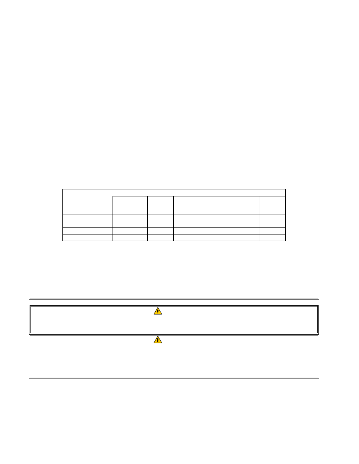
Do remove the 15-pin plug from the controller cable with a pin pusher
before routing it to the fryer and carefully reattach, using the provided
DO use a pin pusher
to remove the 15-pin
plug on the controller
cable for routing.
diagram in section 7.15.
Don’t mount the remote controller on the fryer’s flue cap or on the
bulkhead above the fryer vat.
Don’t cut and splice the remote controller’s cable to facilitate routing it to
the fryer.
DO NOT mount the
controller on the fryer’s
flue cap or on the
bulkhead above the
fryer’s vat
DANGER
No structural material on the fryer should be altered or removed to accommodate
placement of the fryer under a hood. Questions? Call the Frymaster and Dean
Service Department at 1-800-551-8633 or via e-mail at service@frymaster.com
2.4 After Fryers Are Anchored At the Frying Station
DANGER
Hot oil can cause severe burns. Avoid contact. Under all circumstances, oil must be
removed from the fryer before attempting to move it to avoid oil spills, falls and
severe burns. This fryer may tip and cause personal injury if not secured in a
stationary position.
1. Close frypot drain-valve(s) and fill frypot(s) with water to the bottom oil level line.
2. Boil out frypot(s) in accordance with the instructions in Section 5.1.3 of this manual.
3. Drain, clean, and fill frypot(s) with cooking oil. (See Equipment Setup and Shutdown
Procedures in Chapter 3.)
PDF compression, OCR, web optimization using a watermarked evaluation copy of CVISION PDFCompressor
2-3
Page 12
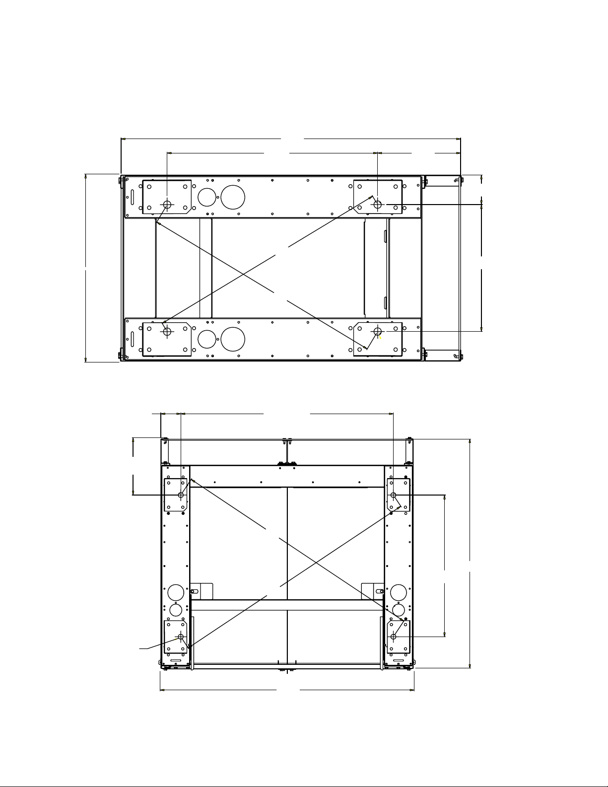
2.5 Dimensions and Weights
Single Fryer: LWH(inches) 28.29 X 15.67 X 45.5 – 190 lbs. empty.
2-Fryer Battery: LWH (inches) 28.30 X 31.45 X 45.5 – 490 lbs. empty.
28.29
17.534 6.913
20.48
15.67
20.48
2.465
10.580
BACK
OF
FRYER UNIT
TYPICAL
7.098
TYPICAL
MOUNTING
HOLES
Ø .625
4 PLACES
2.470
Single Fryer
BACK OF FRYER UNIT
31.62
31.62
26.316
28.30
17.515
31.45
2-Fryer Battery
PDF compression, OCR, web optimization using a watermarked evaluation copy of CVISION PDFCompressor
2-4
Page 13
PRO SERIES MARINE ELECTRIC FRYERS
CHAPTER 3: OPERATING INSTRUCTIONS
3.1 Equipment Setup and Shutdown Procedures
Setup
DANGER
Never operate the appliance with an empty frypot. The frypot must be filled with
water, oil or shortening before energizing the elements. Failure to do so will result in
irreparable damage to the elements and may cause a fire.
DANGER
Remove all drops of water from the frypot before filling with oil or shortening.
Failure to do so will cause spattering of hot liquid when the oil or shortening is
heated to cooking temperature.
1. Fill the frypot with oil to the bottom OIL LEVEL line located on the rear of the frypot. This will
allow for oil expansion as heat is applied. Do not fill cold oil any higher than the bottom line;
overflow may occur as heat expands the oil.
NOTE: If solid shortening is used, first raise the elements, then pack the shortening into the
bottom of the frypot. Lower the elements, and then pack the shortening around and over the
elements to the lower mark. It may be necessary to add shortening to bring the level up to the
upper mark after the packed shortening has melted. Cooking oil/shortening capacity of H17
series fryer is 50 lbs. (25 liters) at 70°F (21°C).
DANGER
Never set a complete block of solid shortening on top of the heating elements.
When using solid shortening, always pre-melt the shortening before adding it to the
frypot. If the shortening is not pre-melted, it must be packed down into the bottom of
the frypot and between the elements, and the fryer must be started in the melt-cycle
mode.
Never cancel the melt-cycle mode when using solid shortening. Doing so will result
in damage to the elements and increase the potential for a flash fire.
2. Replace the basket support rack on top of the heating elements.
3. If the fryer is not hard-wired into the power supply, ensure that the power cord is plugged into
the appropriate receptacle. Verify that the face of the plug is flush with the outlet plate, with no
portion of the prongs visible.
PDF compression, OCR, web optimization using a watermarked evaluation copy of CVISION PDFCompressor
3–1
Page 14
4. Ensure that the oil level is at the top OIL LEVEL line when the oil is at its cooking temperature.
It may be necessary to add oil to bring the level up to the upper mark, after it has reached
cooking temperature.
Shutdown
1. Turn the fryer off.
2. Filter the oil and clean the fryers (See Chapters 4 and 5).
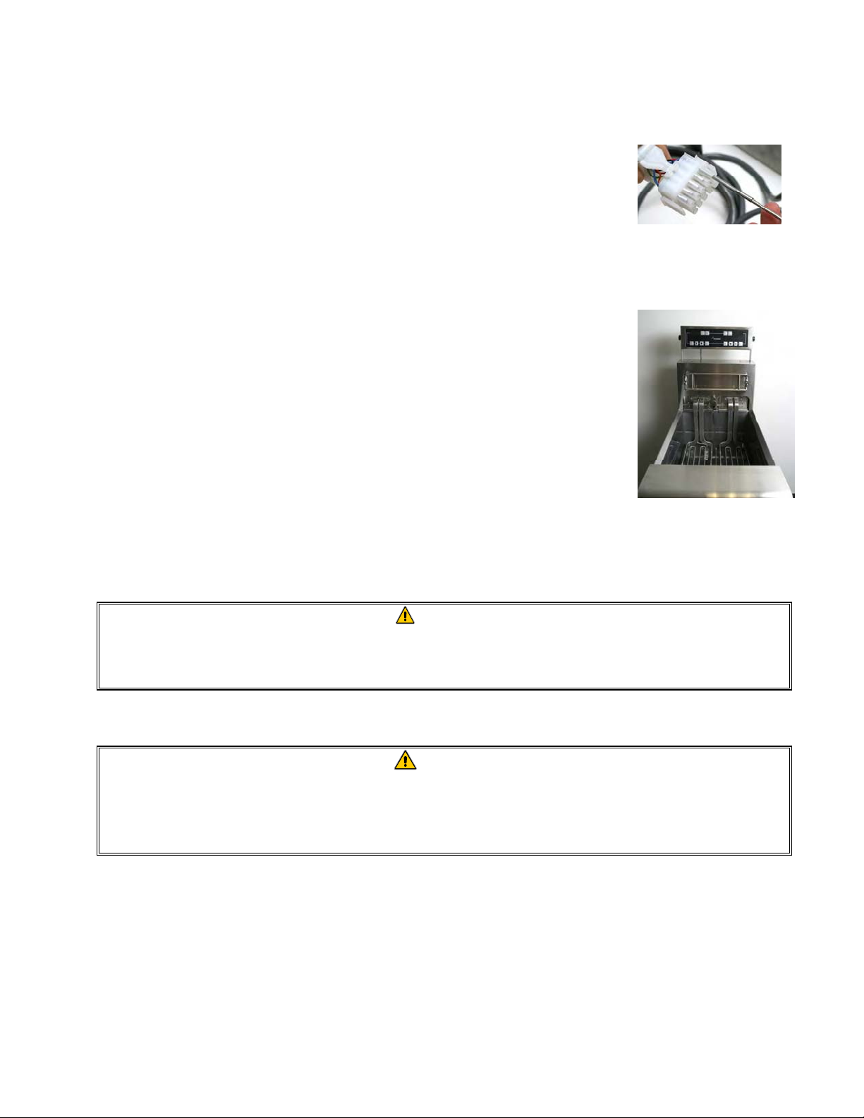
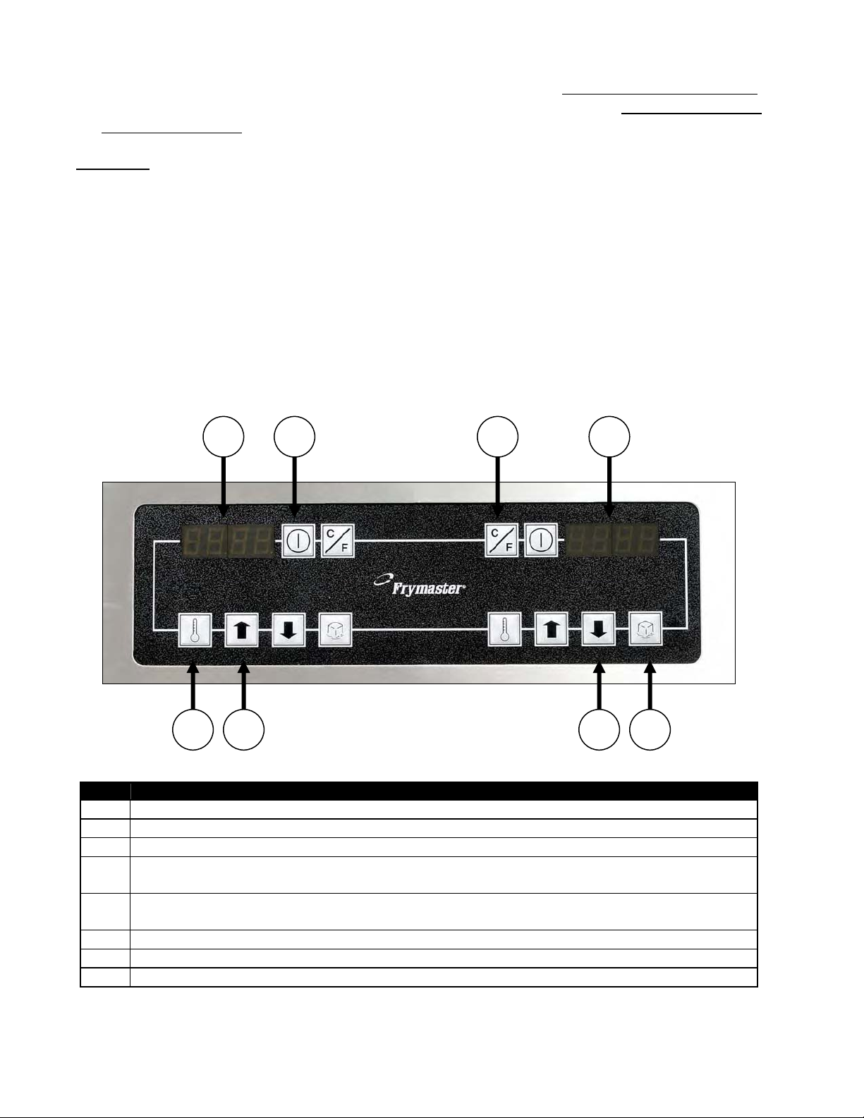
3.2 Operation of the Solid-State Digital Controller
NOTE: Refer to Chapter 4 of this manual for operating instructions for the built-in filtration system.
Fryers configured for marine use are equipped with remotely mounted solid-state digital controllers.
1 2
3 4
5 6 7 8
Marine Solid-State Digital Controller
ITEM DESCRIPTION
1 Lighted Display – LED display for a full-pot fryer. Displays setpoint temperature.
2 On/Off Switch – Switches the power On or Off.
3 C/F Switch – Toggles the display between Fahrenheit and Celsius
Lighted Display- LED Display – Displays current frypot temperature and heat mode light (decimal)
4
will alternately illuminate as the elements cycle on and off.
Temperature / Setpoint Display Switch –Toggles the display between frypot temperature and
5
setpoint temperature.
6 Up Arrow – Raises setpoint temperature.
7 Down Arrow – Lowers the setpoint temperature.
8 Melt-Cycle Cancel Switch – Cancels the melt-cycle mode.
The digital controller, illustrated above, is used to maintain oil at the temperature indicated by the
controller.
PDF compression, OCR, web optimization using a watermarked evaluation copy of CVISION PDFCompressor
3–2
Page 15

The fryer has two built-in high-limit protection features. If the temperature in the frypot reaches
411°F (210°C), an alarm will sound. In the event that the temperature continues to rise, there is a
second and separate high limit circuit that will shut down the system at 425° (218°C), sound an
alarm and display “help”.
A shunt trip device is integrated into the Cruise Line specifications. The shunt trip is a contact,
which is closed by a coil in the fryer’s 24-volt safety circuit. Leads from the shunt trip extend from
the fryer and can be wired to a specialized shipboard circuit breaker. Voltage from the ship passes
through the closed shunt trip on the fryer, keeping the ship’s circuit breaker closed. If the fryer’s
safety circuit opens due to the hi-limit opening or the opening of a drain valve while the fryer is on,
the shunt-trip circuit on the fryer opens, which opens the ship’s circuit breaker, killing power to the
fryer.
The digital controller has no timing features, so the operator must monitor cooking.
WARNING
Before pressing the power switch to the ON position, ensure that the frypot is
properly filled with oil. See Section 3.1.
CONTROLLER OPERATING PROCEDURE
1. Turn the power switch ON.
2. Verify that the control is set to the desired cooking temperature.
3. Press the power switch to the ON position. The POWER light will illuminate.
4. If the frypot temperature is below 180°F (82°C), the controller will automatically enter a warm-
up cycle (often called a melt cycle). The heating elements will cycle on and off repeatedly,
allowing the oil to heat gradually, without scorching. During the warm-up cycle, the heating
mode light (decimal point) will alternately illuminate and go off as the elements cycle on and off.
When the frypot temperature reaches 180°F (82°C), the controller will exit the warm-up cycle
and the heating mode light will remain continuously illuminated.
5. When the oil temperature reaches the setpoint, the elements will cycle OFF and the HEAT light
will go off, indicating that the fryer is ready for the cooking process to begin.
INTRODUCTION
The Digital Controller allows the operator to program th e frypot setpoint and to toggle the display
between the frypot temperature and the programmed setpoint. The setpoint is an operatordetermined frying temperature. When the controller is turned on, it automatically brings the cooking
oil to the setpoint and maintains it at that temperature until the controller is turned off. Units display
the setpoint by default. This controller also features a programmable melt-cycle cancel switch and a
switch for toggling the temperature display between Fahrenheit and Celsius as well as toggling
between the setpoint and the actual temperature.
PDF compression, OCR, web optimization using a watermarked evaluation copy of CVISION PDFCompressor
3–3
Page 16
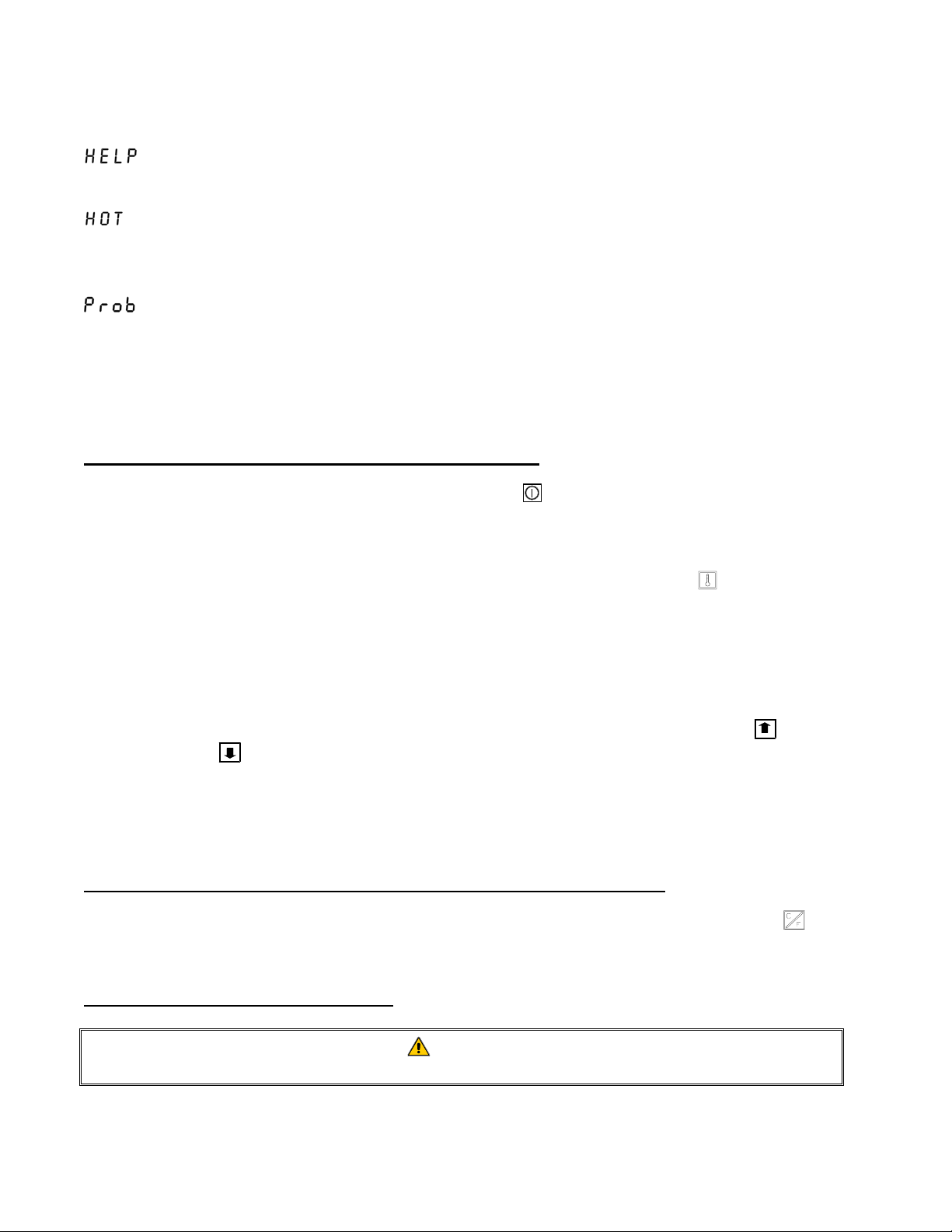
The controller has three error display messages:
, indicating a heating problem or drain valve problem. Turn the fryer off reset the drain
handle and try again. If the error still appears, call the Frymaster hotline.
and actual frypot temperature, indicating that the shortening temperature is above 411°F
(210°C). If this display is seen, turn the fryer off immediately and contact an authorized service
center.
, indicating that the controller has detected a problem in the temperature measuring circuits
and control circuits. Turn the fryer off and contact an authorized service center.
NOTE: This controller is configured for the fryer on which it installed (i.e., gas or electric and full-
or split-pot). Although identical in appearance, controllers configured for use on one type of fryer
are not interchangeable with those configured for use on another type.
CONTROLLER OPERATING INSTRUCTIONS
1. Turn the controller on by pressing the ON/OFF switch .
The controller software version number will display for four seconds then, in non-CE units, the
setpoint temperature will appear in the display. In CE units, the frypot temperature will appear
in the display – to view the setpoint temperature, press the temperature switch for the frypot
in question.
A decimal point will appear between the first two numbers of the display, indicating that the unit
is heating. When the frypot has reached the setpoint temperature, the heat indicator decimal
point will go out, indicating that the fryer is ready for cooking.
2. Adjust the setpoint if necessary. To raise the setpoint temperature, press an up arrow . Press
a down arrow to lower the setpoint temperature.
The display will change at the rate of approximately one-degree per second initially. If the arrow
is pressed and held, after a change of about 12°, the rate of change will increase, allowing large
changes in setpoint temperature to be made quickly.
SELECTING FAHRENHEIT OR CELSIUS DISPLAY MODE
To toggle the temperature display between Fahrenheit and Celsius, press the right C/F switch .
The display(s) will change from xxx°F to xxx°C, where “xxx” is the frypot or setpoint temperature.
CANCELING THE MELT-CYLE
DANGER
Do not cancel the melt-cycle mode if using solid shortening!
The melt-cycle is designed to prevent scorching shortening and overheating the frypot or elements
while gradually melting blocks of shortening. The controller automatically starts the fryer in the
PDF compression, OCR, web optimization using a watermarked evaluation copy of CVISION PDFCompressor
3–4
Page 17

melt-cycle mode and remains in this mode until the frypot temperature reaches 180°F (82°C) or the
melt-cycle is cancelled by the operator. If you are not using solid shortening, you may cancel the
melt-cycle.
To cancel the melt-cycle on a full-pot unit, press the right melt-cycle cancel switch . On a splitpot unit, press the left switch for the left frypot or the right switch for the right frypot.
DISABLING OR ENABLING THE MELT-CYCLE CANCEL SWITCH
The controller can be programmed to disable the melt-cycle cancel switch to prevent accidentally
canceling the melt-cycle.
1. With the controller in the OFF mode, press the melt-cycle cancel switch . The display will
show either "0", meaning that the melt-cycle can be bypassed or a "1" meaning that the meltcycle cannot be bypassed.
2. To change the bypass configuration, press and hold the melt-cycle cancel switch for five to six
seconds to toggle the "0" to "1" or "1" to "0". Release the switch when the display shows the
desired setting.
PDF compression, OCR, web optimization using a watermarked evaluation copy of CVISION PDFCompressor
3–5
Page 18
PRO SERIES MARINE ELECTRIC FRYERS
CHAPTER 4: FILTRATION INSTRUCTIONS
4.1 Introduction
The FootPrint Pro filtration system allows the oil in one frypot to be safely and efficiently filtered
while the other frypots in a battery remain in operation. Section 4.2 covers preparation of the filter
system. Operation of the system is covered in section 4.3.
WARNING
The work center supervisor is responsible for ensuring that operators are made
aware of the inherent hazards of operating a hot oil filtering system, particularly the
aspects of oil filtration, draining and cleaning procedures.
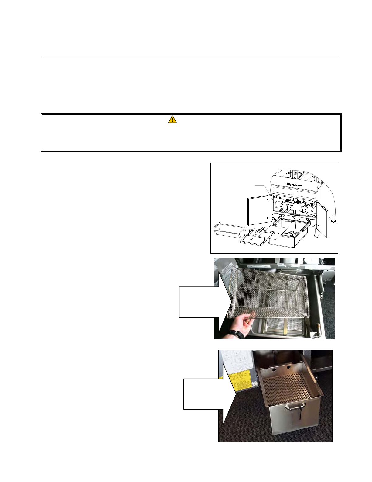
4.2 Preparing the Filter for Use
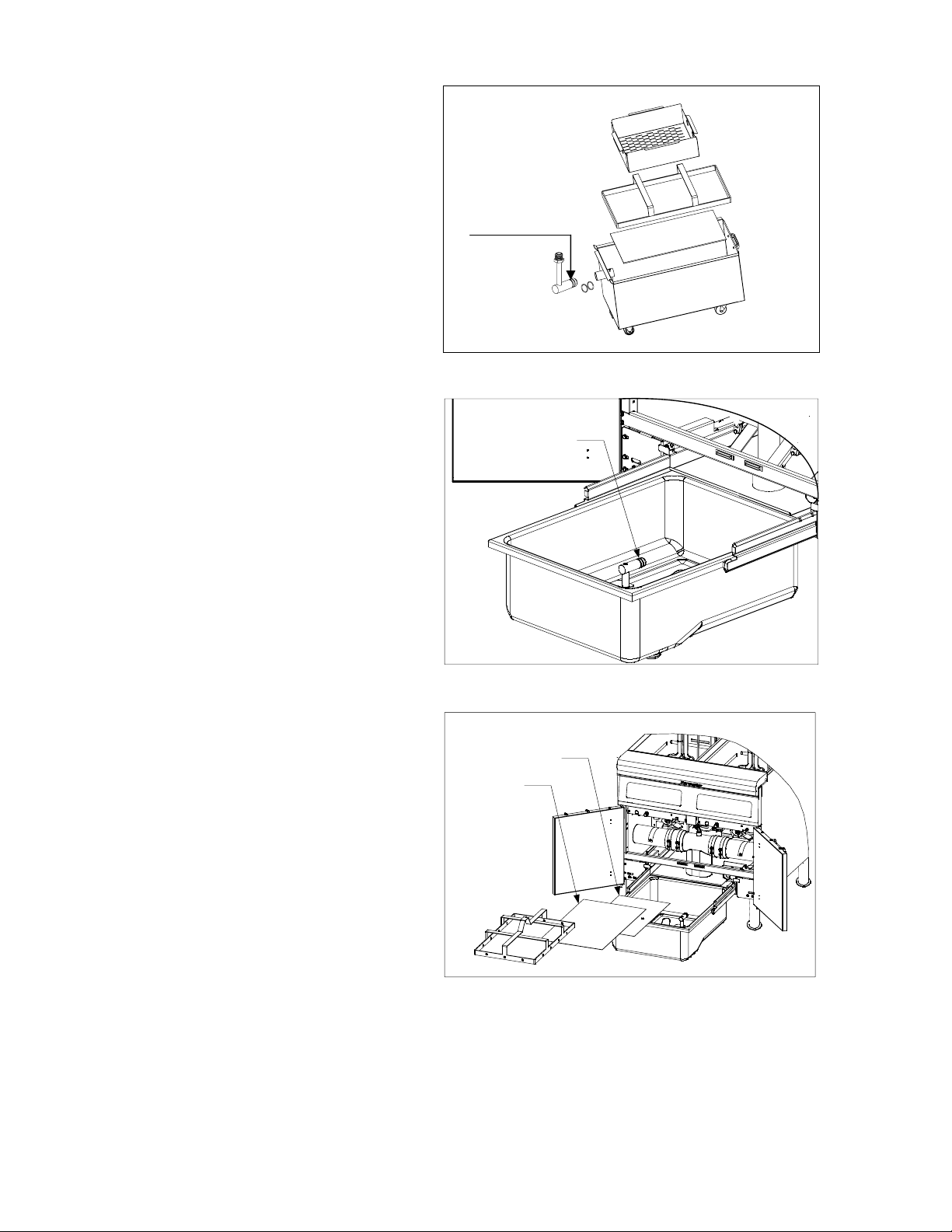
1. Rotate the pan-locking rod to either side
until it clears the filter pan, then pull the
pan out from the cabinet. Remove the
crumb tray, hold-down ring. Remove
the used filter paper in the pan. Remove
the filter paper support screen. Clean
all components with a solution of
detergent and hot water then dry
thoroughly.
The filter pan on the FPPH217 is
equipped with rollers in rails, much like
a kitchen drawer. The pan may be
removed for cleaning or to gain access to
interior components by lifting the front
of the pan to disengage the front rollers,
then pulling it forward until the rear
rollers clear the rails. The pan cover
must not be removed except for
cleaning, interior access, or to allow a
shortening disposal unit (SDU) to be
positioned under the drain. On the
FPH117, the pan slides out on rails, but
when fully removed from the cabinet, it
has wheels to roll on.
FPPH217
Screen and
Filter Pan
FPH117
Screen and
Filter Pan
Rotate the locking rod
to either side to allow
the pan to be pulled
out from the fryer.
PDF compression, OCR, web optimization using a watermarked evaluation copy of CVISION PDFCompressor
4-1
Page 19
2. On the FPH117 fryer, inspect the filte
r
f
r
pan connection fitting to ensure that
both O-rings are in good condition.
The O-rings are located on the tube
spout behind the filter pan at the rear o
the fryer. (See drawing to the right.)
Likewise, on the FPPH217, inspect the
filter pan connection fitting to ensure
that both O-rings are in good condition.
The O-rings are located on the tube
disconnect inside the filter pan as
shown on the drawing down and to the
right.
3. Place the metal filter screen in the cente
of the bottom of the pan, then lay a sheet
of filter paper on top of the pan, overlapping on all sides.
4. Position the hold-down ring over the
filter paper and lower the ring into the
pan, allowing the paper to fold up
around the ring as it is lowered to the
bottom of the pan.
5. When the hold-down ring is in position,
sprinkle one cup of filter powder evenly
over the paper.
6. Replace the crumb tray in the filter pan,
and then push the filter pan back into the
fryer, positioning it all the way to the
back of the cabinet.
Inspect O-Rings here
on FPH117
Inspect O-Rings
here on the
FPH 217
Screen
Filter Paper
PDF compression, OCR, web optimization using a watermarked evaluation copy of CVISION PDFCompressor
4-2
Page 20
4.3 Operation of the Filter
b
p
DANGER
Draining and filtering of oil must be accomplished with care to avoid the possibility
of a serious burn caused by careless handling. The oil to be filtered is at or near
350°F (177°C). Ensure drain handles are in their proper position before operating
any switches or valves. Wear all appropriate safety equipment when draining and
filtering oil.
DANGER
NEVER attempt to drain oil from the fryer with the elements energized! Doing so will
cause irreparable damage to the elements and may cause a flash fire. Doing so will
also void the Frymaster warranty.
1. Ensure that the filter is prepared. See Sec. 4.2
2. Make sure the oil is at operating temperature.
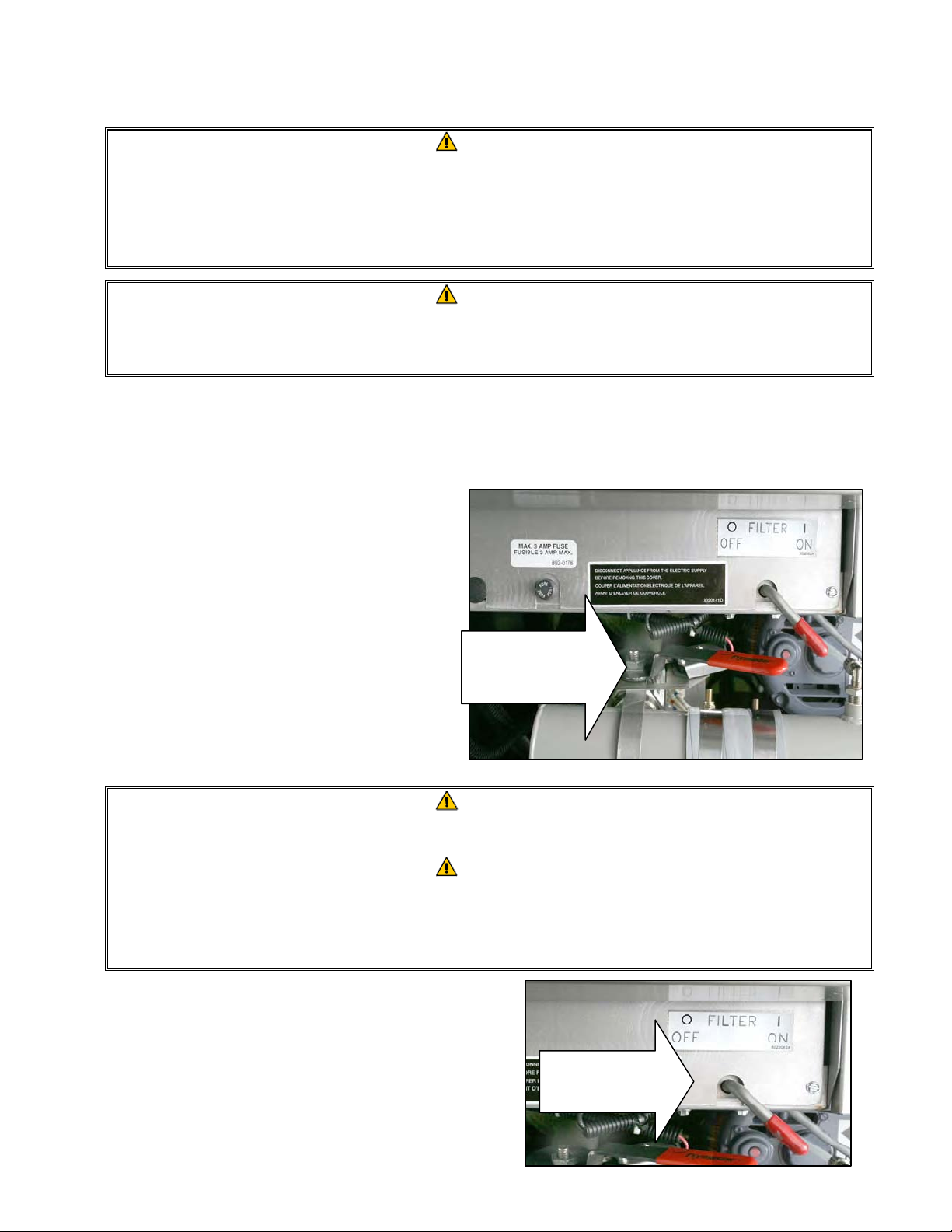
3. Turn the fryer power OFF. Drain the
frypot into the filter pan. Remove the
asket support rack and raise the element
assembly to the up position. If necessary,
use the Fryer's Friend clean-out rod to
clear the drain from inside the frypot.
Open valve by
moving the handle
to the right.
DANGER
Do not drain more than one frypot at a time into the built-in filtration unit to avoid
overflow and spillage of hot oil.
DANGER
NEVER attempt to clear a clogged drain valve from the front of the valve! Hot oil will
rush out creating the potential for severe burns. DO NOT hammer on the drain valve
with the cleanout rod or other objects. Damage to the ball inside will result in leaks
and will void the Frymaster warranty.
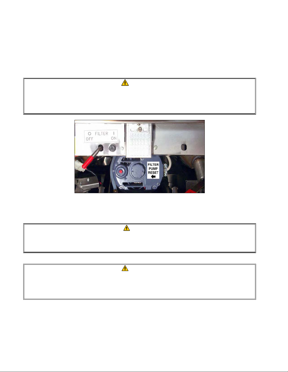
4. After the oil has drained from the frypot,
turn the filter handle to the ON position
to start the pump and begin the filtering
process. Make sure the drain valve is left
open. There may be a slight delay
Turn filter handle
to the ON
osition.
before the pump activates.
PDF compression, OCR, web optimization using a watermarked evaluation copy of CVISION PDFCompressor
4-3
Page 21
5. The filter pump draws the oil through the filter medium and circulates it through the frypot
during a 5-minute process called polishing. Polishing cleans the oil by trapping solid particles in
the filter medium.
6. After 5 minutes, close the drain valve and allow the fryer to refill. Let the filter pump run 10 to
12 seconds after the oil begins to bubble. Turn the filter off.
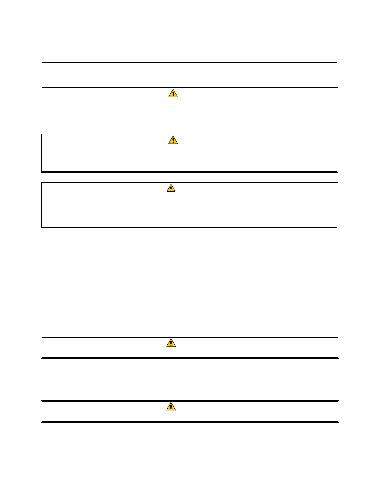
WARNING
The filter pump is equipped with a manual reset switch (see photo below) in case the
filter motor overheats or an electrical fault occurs. If this switch trips, turn OFF
power to the filter system and allow the pump motor to cool 20 minutes before
attempting to reset the switch.
7. Lower the elements into the frypot and reinstall the basket support rack. Ensure the drain valve
is fully closed. (If the drain valve is not fully closed, the fryer will not operate.) Turn the fryer
ON and allow the oil to reach setpoint.
DANGER
The crumb tray must be emptied into a fireproof container at the end of frying
operations each day. Some food particles can spontaneously combust if left soaking
in certain shortening material.
WARNING
Do not bang fry baskets or other utensils on the fryer’s joiner strip. The strip is
present to seal the joint between the fry vessels. Banging fry baskets on the strip to
dislodge shortening will distort the strip, adversely affecting its fit. It is designed for
a tight fit and should only be removed for cleaning.
4.4 Draining and Disposing of Waste Oil
When your oil has reached the end of its usable life, drain the oil into an appropriate container for
transport to the disposal container. Frymaster recommends the use of the Frymaster Shortening
Disposal Unit (SDU). Refer to the documentation furnished with the disposal unit for specific
operating instructions. If a shortening disposal unit is not available, allow the oil to cool to 100°F
PDF compression, OCR, web optimization using a watermarked evaluation copy of CVISION PDFCompressor
4-4
Page 22

(38°C), and then drain the oil into a metal stockpot or similar metal container. When draining is
finished, close the fryer drain valve securely.
DANGER
Allow oil to cool to 100°F (38°C) before draining into an appropriate container for
disposal. When draining oil into a disposal unit, do not fill above the maximum fill
line located on the container.
PDF compression, OCR, web optimization using a watermarked evaluation copy of CVISION PDFCompressor
4-5
Page 23
PRO SERIES MARINE ELECTRIC FRYERS
CHAPTER 5: PREVENTIVE MAINTENANCE
5.1 Cleaning the Fryer
The crumb tray in fryers equipped with a filter system must be emptied into a
fireproof container at the end of frying operations each day. Some food particles
can spontaneously combust if left soaking in certain shortening material.
Never attempt to clean the fryer during the frying process or when the frypot is filled
with hot oil. If water comes in contact with oil heated to frying temperature, it will
cause spattering of the oil, which can result in severe burns to nearby personnel.
Use a commercial-grade cleaner formulated to effectively clean and sanitize
food-contact surfaces. Read the directions for use and precautionary statements
before use. Particular attention must be paid to the concentration of cleaner and the
length of time the cleaner remains on the food-contact surfaces.
5.1.1 Clean Inside and Outside of the Fryer Cabinet – Daily
Clean inside the fryer cabinet with a dry, clean cloth. Wipe all accessible metal surfaces and
components to remove accumulated oil and dust.
DO NOT spray the fryer cabinet with water.
Clean outside the fryer cabinet, with a clean, damp cloth soaked with dishwashing detergent. Wipe
with a clean, damp cloth.
5.1.2 Clean the Built-in Filtration System – Daily
DANGER
DANGER
WARNING
WARNING
Never drain water into the filter pan. Water will damage the filter pump.
There are no periodic preventive maintenance checks and services required for the FootPrint Pro
Filtration System other than daily cleaning of the filter pan and associated components with a
solution of hot water and detergent.
WARNING
Never spray the fryer with water or use water jets to clean this equipment.
PDF compression, OCR, web optimization using a watermarked evaluation copy of CVISION PDFCompressor
5–1
Page 24
5.1.3 Clean the Frypot and Heating Elements – Weekly
DANGER
Never operate the appliance with an empty frypot. The frypot must be filled with
water or oil/shortening before energizing the elements. Failure to do so will result in
irreparable damage to the elements and may cause a fire.
Boiling-Out the Frypot
Before the fryer is first used, it should be boiled out to ensure that residue from the manufacturing
process has been eliminated. Also, after the fryer has been in use for a period of time, a hard film of
caramelized vegetable oil will form on the inside of the frypot. This film should be periodically
removed by following the boil-out procedure that follows.
1. Before switching the fryer(s) ON, close the frypot drain valve(s), then fill the empty frypot with
a mixture of cold water and low-sudsing dishwashing detergent (or a commercially available
boil-out solution). Follow instructions on the container when mixing.
2. Press the fryer ON/OFF switch to the ON position.
3. Set the temperature to 190°F (88°C).
4. Simmer the solution for 45 minutes to one hour. Do not allow the water level to drop below the
bottom oil-level line in the frypot during the boil-out operation.
DANGER
Never leave the fryer unattended during the boil-out process. If the boil-out solution
boils over, turn the fryer off immediately and let the solution cool for a few minutes
before resuming the process.
5. Turn the fryer ON/OFF switch(s) to the OFF position.
6. Add two gallons of water. Drain out the solution into a stockpot and clean the frypot(s)
thoroughly.
WARNING
Do not drain boil-out solution into a shortening disposal unit, a built-in filtration unit,
or a portable filter unit. These units are not intended for this purpose, and will be
damaged by the solution.
7. Refill the frypot(s) with clean water. Rinse the frypot(s) twice, drain and dry with a clean towel.
Thoroughly remove all water from the frypot and elements before refilling the frypot with oil.
PDF compression, OCR, web optimization using a watermarked evaluation copy of CVISION PDFCompressor
5–2
Page 25

DANGER
Remove all drops of water from the frypot before filling with oil or shortening.
Failure to do so will cause spattering of hot liquid when the oil or shortening is
heated to cooking temperature.
5.1.4 Clean Detachable Parts and Accessories – Weekly
Wipe all detachable parts and accessories with a clean, dry cloth. Use a clean cloth saturated with
detergent to remove accumulated carbonized oil on detachable parts and accessories. Rinse the parts
and accessories thoroughly with clean water and wipe dry before reinstalling.
5.2 Annual/Periodic System Inspection
This appliance should be inspected and adjusted periodically by qualified service personnel as
part of the galley material maintenance management (3M) program.
Frymaster recommends that a Factory Authorized Service Technician inspect this appliance at
least annually as follows:
Fryer
• Inspect the cabinet inside and out, front and rear for excessive oil build-up and/or oil migration.
• Verify that the heating element wires are in good condition and that leads have no visible fraying
or insulation damage and that they are free of oil migration build-up.
• Verify that heating elements are in good condition with no carbon/caramelized oil build-up.
Inspect the elements for signs of extensive dry-firing.
• Verify that the tilt mechanism is working properly when lifting and lowering elements and that
the element wires are not binding and/or chafing.
• Verify the heating-element amp-draw is within the allowed range as indicated on the appliance’s
rating plate.
• Verify that the temperature and high-limit probes are properly connected, tightened and
functioning properly, and that mounting hardware and probe guards are present and properly
installed.
• Verify that component box and contactor box components (i.e. controller, relays, interface
boards, transformers, contactors, etc.) are in good condition and free from oil migration build-up
and other debris.
• Verify that component box and contactor box wiring connections are tight and that wiring is in
good condition.
• Verify that all safety features (i.e. contactor shields, drain safety switches, hood shunts, reset
switches, etc.) are present and functioning properly.
PDF compression, OCR, web optimization using a watermarked evaluation copy of CVISION PDFCompressor
5-3
Page 26

• Verify that the frypot is in good condition and free of leaks and that the frypot insulation is in
serviceable condition.
• Verify that all wiring harnesses and wiring connections are tight and in good condition.
Built-In Filtration System
• Inspect all oil-return and drain lines for leaks and verify that all connections are tight.
• Inspect the filter pan for leaks and cleanliness. If there is a large accumulation of crumbs in the
crumb basket, instruct the supervisor that the crumb basket must be emptied into a fireproof
container and cleaned daily.
• Verify that all O-rings and seals (including those on quick-disconnect fittings) are present and in
good condition. Replace O-rings and seals if worn or damaged.
• Check filtration system integrity as follows:
− Verify that filter pan cover is present and properly installed.
− With the filter pan empty, place each oil return handle, one at a time, in the ON position. Verify
that the pump activates and that bubbles appear in the cooking oil of the associated frypot.
− Close all oil return valves (i.e., place all oil return handles in the OFF position). Verify proper
functioning of each oil return valve by activating the filter pump using the lever on one of the oil
return handle microswitches. No air bubbles should be visible in any frypot.
− Verify that the filter pan is properly prepared for filtering, then drain a frypot of oil heated to
350°F into the filter pan and close the frypot drain valve. Place the oil return handle in the ON
position. Allow all oil to return to the frypot (indicated by bubbles in the oil). Return the oil
return handle to the OFF position. The frypot should have refilled in no more than 2 minutes and
30 seconds.
PDF compression, OCR, web optimization using a watermarked evaluation copy of CVISION PDFCompressor
5–4
Page 27

PRO SERIES MARINE ELECTRIC FRYERS
CHAPTER 6: OPERATOR TROUBLESHOOTING
6.1 Introduction
This section provides an easy reference guide to some of the common problems that may occur
during the operation of this equipment. The troubleshooting guides that follow are intended to help
correct, or at least accurately diagnose, problems with this equipment. Although the chapter covers
the most common problems reported, you may encounter problems that are not covered. In such
instances, the Frymaster Technical Services staff will make every effort to help you identify and
resolve the problem.
When troubleshooting a problem, always use a process of elimination starting with the simplest
solution and working through to the most complex. Never overlook the obvious – anyone can forget
to plug in a cord or fail to close a valve completely. Most importantly, always try to establish a clear
idea of why a problem has occurred. Part of any corrective action involves taking steps to ensure
that it doesn’t happen again. If a controller malfunctions because of a poor connection, check all
other connections, too. If a fuse continues to blow, find out why. Always keep in mind that failure
of a small component may often be indicative of potential failure or incorrect functioning of a more
important component or system.
Before calling a service agent or the Frymaster HOTLINE (1-800-551-8633) or
contacting via e-mail at service@frymaster.com:
• Verify that electrical cords are plugged in and that circuit breakers are on.
• Verify that frypot drain valves are fully closed.
DANGER
Hot oil will cause severe burns. Never attempt to move this appliance when filled
with hot oil or to transfer hot oil from one container to another.
DANGER
This equipment should be disconnected from the electrical power supply when
servicing, except when electrical circuit tests are required. Use extreme care when
performing such tests.
This appliance may have more than one electrical power supply connection point.
Disconnect all power cords before servicing.
Inspection, testing, and repair of electrical components should be performed by
authorized personnel only.
PDF compression, OCR, web optimization using a watermarked evaluation copy of CVISION PDFCompressor
6-1
Page 28

6.2 Troubleshooting
6.2.1 Control and Heating Problems
Problem Probable Causes Corrective Action
A. Power cord is not plugged in or
circuit breaker is tripped.
B. Controller has failed.
Controller won't
activate.
C. Power supply component or
interface board has failed.
A. Drain valve is open.
B. Controller has failed.
Fryer does not heat
or heat after
filtering.
C. One or more other components
have failed.
A. Plug power cord in and verify
that circuit breaker is not
tripped.
B. If available, substitute a
controller known to be working
for the suspect controller. If the
substitute controller functions
correctly, order a new controller.
C. If any of the components in the
power supply system (including
the transformer and interface
board) fail, power will not be
supplied to the controller and it
will not function. Determining
which component has failed is
beyond the scope of operator
troubleshooting. Call FASC.
A. This fryer is equipped with a
drain safety switch that prevents
the heating element from being
energized if the drain valve is
not fully closed. Verify that the
drain valve is fully closed.
B. If available, substitute a
controller known to be working
for the suspect controller. If the
substitute controller functions
correctly, order a new controller.
C. If the circuitry in the fryer
control system cannot determine
the frypot temperature, the
system will not allow the
element to be energized or will
de-energize the element if it is
already energized. If the
contactor, element, or associated
wiring fails, the element will not
energize. Determining which
specific component is
malfunctioning is beyond the
scope of operator
troubleshooting. Call FASC.
PDF compression, OCR, web optimization using a watermarked evaluation copy of CVISION PDFCompressor
6-2
Page 29

Problem Probable Causes Corrective Action
This is normal. The standard
operational mode for the controller
is for the elements to cycle on and
Fryer repeatedly
cycles on and off
when first started.
Fryer heats until
high limit trips with
heat indicator ON.
Fryer heats until
high limit trips
without heat
indicator ON.
Fryer stops heating
with heat indicator
ON.
Fryer is in melt-cycle mode.
Temperature probe or controller has
failed.
Contactor or controller has failed.
The high limit thermostat or
contactor has failed.
off until the temperature in the
frypot reaches 180ºF (82°C). The
purpose of the melt-cycle is to
allow controlled melting of solid
shortening to prevent scorching
and flash fires or damage to the
element.
If available, substitute a controller
known to be working for the
suspect controller. If the substitute
controller functions correctly,
order a new controller. If
substitution of the controller does
not resolve the problem, the most
likely cause is a failed temperature
probe.
If available, substitute a controller
known to be working for the
suspect controller. If the substitute
controller functions correctly,
order a new controller. If
substitution of the controller does
not resolve the problem, the most
likely cause is a contactor failed in
the closed position.
The fact that the heat indicator is
ON indicates that the controller is
functioning properly and is calling
for heat. The hi-limit thermostat
functions as a normally closed
switch. If the thermostat fails, the
"switch" opens and power to the
elements is shut off. If the
contactor fails to close, no power is
supplied to the elements.
Determining which component has
failed is beyond the scope of
operator troubleshooting. Call
FASC.
PDF compression, OCR, web optimization using a watermarked evaluation copy of CVISION PDFCompressor
6-3
Page 30

6.2.2 Filtration Problems
Problem Probable Causes Corrective Action
A. Verify that the power cord is
Filter pump won't
start.
Filter pump runs
but oil does not
return to frypot and
there is no bubbling
oil.
A. Power cord is not plugged in or
circuit breaker is tripped.
B. Pump motor has overheated
causing the thermal overload
switch to trip.
C. Blockage in filter pump.
Test: Close the drain valve and
pull the filter pan out from the
fryer. Activate the pump. If the
pump motor hums for a short time
then stops, the probable cause is
blockage of the pump itself.
Blockage in filter pan suction tube.
Test: Close the drain valve and pull
the filter pan out from the fryer.
Activate the pump. If the air or
bubbling oil occurs, there is a
blockage in the filter pan suction
tube.
fully plugged in. If so, verify
that circuit breaker is not
tripped.
B. If the motor is too hot to touch
for more than a few seconds, the
thermal overload switch has
probably tripped. Allow the
motor to cool at least 20
minutes then press the Pump
Reset Switch.
C. Pump blockages are usually
caused by sediment buildup in
the pump due to improperly
sized or installed filter paper
and failure to use the crumb
screen.
The blockage may be caused by
sediment buildup or, if solid
shortening is used, solidified
shortening in the tube. Use a thin,
flexible wire to remove the
blockage.
Filter pump runs,
but oil return is very
slow and bubbling
oil occurs.
PDF compression, OCR, web optimization using a watermarked evaluation copy of CVISION PDFCompressor
A. Improperly installed filter pan
components.
(continued on the following page)
6-4
A. Verify that filter screen is in
bottom of pan with paper top of
screen.
Verify that o-rings are present
and in good condition on filter
pan connection fitting.
Page 31

Problem Probable Causes Corrective Action
B. In order to properly filter, the
oil or shortening should be at
or near 350ºF (177°C). At
temperatures lower than this,
Filter pump runs,
but oil return is very
slow and bubbling
oil occurs.
B. Attempting to filter with oil or
shortening that is not hot enough.
the oil becomes too thick to
pass through the filter medium
easily, resulting in much slower
oil return and eventual
overheating of the filter pump
motor. Make sure oil is at or
near frying temperature before
draining oil into filter pan.
PDF compression, OCR, web optimization using a watermarked evaluation copy of CVISION PDFCompressor
6-5
Page 32

PRO SERIES MARINE ELECTRIC FRYERS
CHAPTER 7: SERVICE PROCEDURES
7.1 General
Before performing any maintenance on this equipment, disconnect the fryer from the electrical
power supply.
When electrical wires are disconnected, it is recommended that they be marked in such a way as to
facilitate re-assembly.
7.2 Replacing a Remote Digital Controller
1. Unplug all power cords.
2. Unplug the 15-pin connector from the back of the controller.
3. Remove the mounting screws.
4. Reassemble in reverse order to complete the replacement and return the fryer to service.
7.3 Replacing Component Box Components
1. Unplug all electrical power cords.
2. On the FPH17 remove the 2 screws securing the front panel and it will swing open from the top.
3. On the FPPH17 remove the screw in the top center of the front panel bezel. Lift up on the bezel
to disengage the tabs on its lower edge from the panel frame and pull towards you to remove
panel.
4. Disconnect the wiring from the component to be replaced, being sure to make a note of where
each wire was connected.
NOTE: If replacing the interface board, connectors J1 and J2 must also be disconnected from
the 12-pin connectors on the rear of the component box, directly behind the interface board.
5. Dismount the component to be replaced and install the new component, being sure that any
required spacers, insulation, washers, etc. are in place.
NOTE: If more room to work is required, the control panel frame and top cap assembly may be
removed by removing the hex head screws that secure it to the fryer cabinet (see illustration
below). If this option is chosen, all control panel assemblies must be removed per steps 1 and 2
above. The cover plate on the lower front of the component box may also be removed if desired.
Removing the component box itself from the fryer is not recommended due to the difficulty
PDF compression, OCR, web optimization using a watermarked evaluation copy of CVISION PDFCompressor
7-1
Page 33

involved in disconnecting and reconnecting the oil-return valve rods, which pass through
openings in the component box.
Remove these three
screws at each end.
Remove these two screws
from the center supports.
Removing the Control Panel Frame and Top Cap Assembly
6. Reconnect the wiring disconnected in step 3, referring to your notes and the wiring diagrams on
the fryer door to ensure that the connections are properly made. Also, verify that no other wiring
was disconnected accidentally during the replacement process.
7. Reassemble in reverse order to complete the replacement and return the fryer to service.
7.4 Replacing a Temperature Probe or High-Limit Thermostat
1. Remove the filter pan and lid from the unit. Drain the frypots into a Shortening Disposal Unit
(SDU) or other appropriate container.
DANGER
DO NOT drain more than one full frypot into the SDU at one time.
2. Disconnect the fryer from the electrical power supply and reposition it to gain access to the rear
of the fryer.
3. Remove the tilt housing and back panels from the fryer. The tilt housing must be removed first in
order to remove the upper back panel. To remove the tilt housing, raise the elements and allow
them to rest on the basket support racks as shown in the photo below.
PDF compression, OCR, web optimization using a watermarked evaluation copy of CVISION PDFCompressor
7-2
Page 34

Next, remove the hex head screws from the rear edge of the housing. The housing can then be
lifted straight up and off the fryer. Lift up on the upper back panel to disengage the tabs on its
upper corners from the cutouts in the fryer frame.
4. Disconnect the wire harness at connector C6 and, using a pin pusher, disconnect the probe leads
or high-limit leads from the connector. (Mark each wire for re-assembly.)
5. If replacing a temperature probe, remove the screw securing the probe bracket to the element
and slide the bracket off the element and probe. Pull the probe out of the tilt housing assembly,
install the replacement probe, and reattach the element bracket. Secure the upper portion of the
probe with a replacement metal wire tie.
Probe Leads
Probe Bracket
Metal Wire Ti e
If replacing a high-limit thermostat, unscrew the thermostat to be replaced. Apply Loctite
™
PST
567 or equivalent sealant to the threads of the replacement and screw it securely into the frypot.
6. If a temperature probe was replaced, insert the probe leads into the connector (see left
illustration below). For full-vat units or the left half (as viewed from the rear of the fryer) of a
dual-vat unit, the red lead goes into position 6 and the white into position 7. For the right half of
a dual-vat unit (as viewed from the rear of the fryer), the red lead goes into position 12 and the
white into position 13.
Rib marks Position 1
13
7
6
12
Probe Lead Positions High-Limit Lead Positions
10
4
11
5
If a high-limit thermostat was replaced, insert the leads into the connector (see right illustration
above). For full-vat units or the left half of a dual-vat unit (as viewed from the rear of the fryer),
the leads go into positions 4 and 5 of the connector. For the right half of a dual-vat unit (as
viewed from the rear of the fryer), the leads go into positions 10 and 11. In either case, polarity
does not matter.
7. Reinstall the back panels and tilt housing to complete the installation, then reverse steps 1 and 2
to return the fryer to service.
PDF compression, OCR, web optimization using a watermarked evaluation copy of CVISION PDFCompressor
7-3
Page 35

7.5 Replacing a Heating Element
1. Perform steps 1-3 of section 7.4, Replacing a Temperature Probe.
2. On dual-vat fryers, and on full-vat fryers where the temperature probe is attached to the element
being replaced, disconnect the wire harness containing the probe wiring (connector C6). Using a
pin pusher, disconnect the probe wires from the connector.
3. On the front of the contactor box, disconnect the 6-pin connector for the left element (as viewed
from the front of the fryer) or the 9-pin connector for the right element and pull the harness out
through the rear of the fryer. Press in on the tabs on each side of the connector while pulling
outward on the free end to extend the connector and release the element leads (see photo below).
Pull the leads out of the connector and out of the plastic wire loom.
Note: Liquid
resistant
seals.
4. Raise the element to the full up position and disconnect the element springs.
5. Remove the nuts and machine screws that secure the element to the tilt plate assembly and pull
the element out of the frypot. NOTE: Full-vat elements consist of two dual-vat elements
clamped together. For full-vat units, remove the element clamps before removing the nuts and
machine screws that secure the element to the tilt plate assembly.
6. If applicable, recover the probe bracket and probe from the element being replaced and install
them on the replacement element, then install the replacement element in the frypot, securing it
with the nuts and screws removed in Step 5.
7. Route the element leads through the wire loom to prevent chafing and press the pins into the
connector in accordance with the diagram below, then close the connector to lock the leads in
place. NOTE: It is critical that the wires be routed through the loom to prevent chafing.
Pip marks Position 1
1
2
3
1
2
3
5
6
5L 4L6L 1L2L3L
6
4
5R 4R6R 1R2R3R
4
5
789
PDF compression, OCR, web optimization using a watermarked evaluation copy of CVISION PDFCompressor
7-4
Page 36

8. Insert the element connector into the receptacle on the front of the contactor box, ensuring that
the latches lock.
9. If disconnected in step 2, insert the temperature probe leads into the wiring harness connector
(see illustration below). For full-vat units or the right half of a dual-vat unit, the red lead goes
into position 6 and the white into position 7. For the left half of a dual-vat unit, the red lead goes
into position 12 and the white into position 13. NOTE: Right and left refer to the fryer as
viewed from the rear.
13
7
Rib marks Position 1
6
12
10. If disconnected in step 2, reconnect connector C6 of the wiring harness.
11. Reconnect the element springs and lower the element back down onto the basket rack.
12. Reinstall the tilt housing and back panels, reposition the fryer under the exhaust hood, and
reconnect it to the electrical power supply.
7.6 Replacing Contactor Box Components (See Illustrations pages 8-15 and 8-17)
1. If replacing a contactor box above the built-in filter system, remove the filter pan and lid from
the unit. Drain the frypots into a Shortening Disposal Unit (SDU) or other appropriate container.
If replacing a contactor box in a non-filter unit, drain the frypot above the box into a Shortening
Disposal Unit (SDU) or other appropriate container.
DANGER
DO NOT drain more than one full frypot into the SDU at one time.
2. Disconnect the fryer from the electrical power supply.
3. Unplug the wiring harnesses from the contactor box to be serviced.
4. On the FPH17 fryers remove the screw securing the contactor box in place. Lift the contactor
box and push back slightly to release the tabs holding the box in the rear of the cabinet. Lift and
pull the box forward to allow access to the plugs at the rear of the unit.
5. On the FPPH17 fryers remove the two screws that secure the box in place. (See drawing on the
following page.)
PDF compression, OCR, web optimization using a watermarked evaluation copy of CVISION PDFCompressor
7-5
Page 37

Remove these screws to dismount the left contactor box.
The right contactor box is secured in a similar manner.
6. Carefully lower the box to the floor and pull it out the front of the fryer. Remove the top cover
to access contactors and other components.
7. After performing necessary service, reverse steps 1-6 to return the fryer to operation.
7.7 Replacing a Frypot
1. Drain the frypot into the filter pan or, if replacing a frypot over the filter system, into a
Shortening Disposal Unit (SDU) or other appropriate container. If replacing a frypot over the
filter system, remove the filter pan and lid from the unit.
DANGER
DO NOT drain more than one full frypot into the SDU at one time.
2. Disconnect the fryer from the electrical power supply and reposition it to gain access to both the
front and rear.
3. Remove the screw in the top center of the front panel bezel. Lift up on the bezel to disengage the
tabs on its lower edge from the panel frame and pull towards you to remove panel.
4. Remove the tilt housing and back panels from the fryer. The tilt housing must be removed first in
order to remove the upper back panel. To remove the tilt housing, raise the elements and allow
them to rest on the basket support racks (see photo on page 7-2).
Next, remove the hex head screws from the rear edge of the housing. The housing can then be
lifted straight up and off the fryer. Lift up on the upper back panel to disengage the tabs on its
upper corners from the cutouts in the fryer frame.
5. Dismount the top cap by removing the hex head screws at each end that secure it to the control
panel frame.
6. Remove the hex head screw that secures the front of the frypot to the cabinet cross brace.
7. Remove the top-connecting strip that covers the joint with the adjacent frypot.
PDF compression, OCR, web optimization using a watermarked evaluation copy of CVISION PDFCompressor
7-6
Page 38

8. Open the drain tube cleanout covers, unscrew the retainer nuts from the drain valve nipples, and
remove the tube assembly from the fryer. (If replacing a frypot over the built-in filtration
system, unscrew the vacuum-breaker tube fitting from the drain tube assembly also.)
9. Remove the covers from the drain safety switch and disconnect the switch wiring at the switch.
10. At the rear of the fryer, unplug the C6 connector and, using a pin pusher, disconnect the high-
limit thermostat leads.
11. Disconnect the oil return flexlines at the frypot ends.
12. Raise the elements to the full up position and disconnect the element springs.
13. Remove the machine screws and nuts that secure the tilt plate and element assembly to the
frypot. Carefully lift the tilt plate and element assembly from the frypot and secure it to the cross
brace on the rear of the fryer with wire ties or tape.
14. Carefully lift the frypot from the fryer and place it upside down on a stable work surface.
15. Recover the drain valves, oil return flexline connection fittings, and high-limit thermostats from
the frypot. Apply Loctite™ PST 567 or equivalent sealant to the threads of the recovered parts
and install them in the replacement frypot.
16. Carefully lower the replacement frypot into the fryer. Reinstall the hex head screw removed in
step 7 to attach the frypot to the fryer.
17. Position the tilt housing and element assembly in the frypot and reinstall the machine screws and
nuts removed in step 14.
18. Reconnect the oil return flexlines to the frypot, and replace aluminum tape, if necessary, to
secure heater strips to the flexlines.
19. Insert the high-limit thermostat leads disconnected in step 11 (see illustration on page 7-4 for pin
positions).
20. Reconnect the drain safety switch wiring to the switches in accordance with the diagram below
then reinstall the switch covers.
58C BLK
57C RED
55C BLK
56C RED
NC
NO
NC
NO
COM
COM
RIGHT
DRAIN SAFETY SWITCH
LEFT
DRAIN SAFETY SWITCH
(DUAL-VAT ONLY)
21. Reinstall the drain tube assembly.
PDF compression, OCR, web optimization using a watermarked evaluation copy of CVISION PDFCompressor
7-7
Page 39

22. Reinstall the tilt housing and back panels, top cap, and top connecting strip.
23. Reinstall controllers in the control panel frame and reconnect the wiring harnesses and ground
wires.
24. Reposition the fryer under the exhaust hood and reconnect it to the electrical power supply.
7.8 Built-in Filtration System Service Procedures
7.8.1 Filtration System Problem Resolution
One of the most common causes of filtration problems is placing the filter paper on the bottom of the
filter pan rather than over the filter screen.
CAUTION
Ensure that filter screen is in place prior to filter paper placement and filter pump
operation. Improper screen placement is the primary cause of filtration system
malfunction.
Whenever the complaint is “the pump is running, but no oil is being filtered,” check the installation
of the filter paper, and ensure that the correct size is being used. While you are checking the filter
paper, verify that the O-ring on the bottom of the filter pan is present and in good condition. A
missing or worn O-ring allows the pump to take in air and decreases its efficiency. Also, oil leaks
on the floor each time a vat is drained.
If the pump motor overheats, the thermal overload will trip and the motor will not start until it is
reset. If the pump motor does not start, press the red reset switch (button) located on the rear of the
motor.
If the pump starts after resetting the thermal overload switch, then something is causing the motor to
overheat. A major cause of overheating is when several frypots are filtered sequentially, thus
overheating the pump and motor. Allow the pump motor to cool at least 30 minutes before resuming
operation. Pump overheating can be caused by:
Sediment Particle
• Solidified shortening in the pan or filter lines, or
• Attempting to filter unheated oil (cold oil is more
Oil Flow
viscous, overloading the pump motor and causing
it to overheat).
If the motor runs but the pump does not, there is a
blockage in the pump. Incorrectly sized or installed
paper/pads will allow food particles and sediment to pass
Sediment Particle
Up for reverse
through the filter pan and into the pump. When sediment
enters the pump, the gears bind, causing the motor to
overload, again tripping the thermal overload. Shortening
Down for forward
that has solidified in the pump will also cause it to seize,
with the same result.
A pump seized by debris or hard shortening can usually
PDF compression, OCR, web optimization using a watermarked evaluation copy of CVISION PDFCompressor
7-8
Page 40

be freed by manually moving the gears with a screwdriver or other instrument.
Disconnect power to the filter system, remove the input plumbing from the pump, and use a
screwdriver to manually turn the gears.
● Turning the pump gears in reverse will release a hard particle.
● Turning the pump gears forward will push softer objects and solid shortening through the
pump and allow free movement of the gears.
Incorrectly sized or installed paper/pads will also allow food particles and sediment to pass through
and clog the suction tube on the bottom of the filter pan. Particles large enough to block the suction
tube may indicate that the crumb tray is not being used. Pan blockage can also occur if shortening is
left in the pan and allowed to solidify. Blockage removal can be accomplished by forcing the item
out with an auger or drain snake. Compressed air or other pressurized gases should not be used to
force out the blockage.
7.8.2 Replacing the Filter Motor, Filter Pump and Related Components
1. Remove the filter pan and lid from the unit. Drain the frypots into a Shortening Disposal Unit
(SDU) or other appropriate container.
DANGER
DO NOT drain more than one full frypot into the SDU at one time.
2. Disconnect the fryer from the electrical power supply and reposition it to gain access to both the
front and rear.
3. Remove the two lower back panels, unplug the wiring harnesses from the contactor boxes, and
remove the two screws that secure one of the boxes in place (it doesn’t matter which one; see
illustration on page 7-6). NOTE: If you remove the screws from both boxes at the same time,
the boxes will jam against each other and neither can be removed.
4. Carefully lower the box to the floor and pull it out the front of the fryer. Remove the remaining
box following the same procedure.
5. Disconnect the two flexlines running to the oil-return manifold at the rear of the fryer. Remove
the nut and bolt that secures the bridge to the oil-return manifold. (See drawing below.)
Disconnect Vacuum-Breaker
Disconnect Pump
Solenoid flexline here.
Sole n o id fle x lin e h e re .
PDF compression, OCR, web optimization using a watermarked evaluation copy of CVISION PDFCompressor
7-9
Page 41

6. Disconnect the pump suction flexline at the filter pan connection end.
Disconnect Pump
Suction flexline here.
7. Remove the cover plate from the front of the motor and disconnect the motor wires.
8. Unplug the 15-pin connector from the rear of the left component box and, using a pin pusher,
disconnect the solenoid valve wires (pins 4, 6, 10 and 12). NOTE: If the vacuum-breaker
solenoid valve is connected to the manifold rather than the pump, its wires (pins 4 and 6) do not
need to be disconnected.
9. Remove the two nuts and bolts that secure the front of the bridge to the cross brace and carefully
slide the bridge rearward off the cross brace until its front end can be lowered to the floor. Be
careful not to let the rear of the bridge slip off the manifold at this point. NOTE: In some early
production units, the bridge will not slide far enough to the rear to clear the front brace. In such
cases, the front brace must be removed. It is held in place by two hex head screws on each end
and a nut and bolt inside the brace near each end.
10. Get a good grip on the bridge, carefully pull it forward off the oil-return manifold, and lower the
entire assembly to the floor. Once on the floor, pull the assembly out the front of the fryer.
11. When required service has been completed, reverse steps 6-12 to reinstall the bridge. NOTE:
The black motor wires go on the top terminal, the white on the bottom. The pump solenoid valve
wires go in positions 10 and 12 of the 15-pin connector; the vacuum-breaker solenoid valve
wires go in positions 4 and 6. In both cases, polarity does not matter.
12. Once the bridge is back in place, reverse steps 4 and 5 to reinstall the contactor boxes.
13. Reconnect the unit to the electrical power supply, and verify that the pump is functioning
correctly (i.e., when a filter handle is placed in the ON position, the motor should start and there
should be strong suction at the intake fitting and outflow at the power shower or rear flush port).
14. When proper operation has been verified, reinstall the back panels and the filter pan and lid, and
return the fryer to service.
PDF compression, OCR, web optimization using a watermarked evaluation copy of CVISION PDFCompressor
7-10
Page 42

7.8.3 Replacing the Filter Transformer or Filter Relay
Remove the left controller from the fryer to expose the interior of the left component box. The filter
transformer and relay are located as shown in the illustration below. NOTE: The right component
box is identical to the left except that the filter transformer and relay are not present.
Filter Relay
Filter Transformer
PDF compression, OCR, web optimization using a watermarked evaluation copy of CVISION PDFCompressor
7-11
Page 43

7.9 Interface Board Diagnostic Chart
The following diagram and charts provide ten quick system checks that can be performed using only
a multimeter.
Diagostic LEDs
Diagnostic LED Legend
CMP indicates power from 12V transformer
24 indicates power from 24V transformer
HI (RH) indicates output (closed) from right latch
relay
HI (LH) indicates output (closed) from left latch
relay
HT (RH) indicates output from right heat relay
HT (LH) indicates output from left heat relay
AL (RH) indicates output (open) from right latch
relay
AL (LH) indicates output (open) from left latch
relay
K1
Left
Latch
Relay
K2
Left
Heat
Relay
23
6
5
8
9
12
11
15
14
K3 K4
1
4
7
10
13
Right
Heat
Relay
Right
Latch
Relay
4
1
7
10
5
2
8
11
6
3
9
12
4
1
7
10
5
2
8
11
6
3
9
12
Test Points
J1 Left J2 Right
Meter Setting Test Pin Pin Results
12 VAC Power 50 VAC Scale 1 of J2 3 of J2 12-16 VAC
24 VAC Power 50 VAC Scale 2 of J2 Chassis 24-30 VAC
*Probe Resistance (RH) R X 1000 OHMS 11 of J2 12 of J2 See Chart
*Probe Resistance (LH) R X 1000 OHMS 3 of J1 2 of J1 See Chart
Hi-Limit Continuity (RH) R X 1 OHMS 7 of J2 4 of J2 0 - OHMS
Hi-Limit Continuity (LH) R X 1 OHMS 4 of J1 7 of J1 0 - OHMS
Latch Contactor Coil (RH) R X 1 OHMS 8 of J2 Chassis 3-10 OHMS
Latch Contactor Coil (LH) R X 1 OHMS 5 of J1 Chassis 3-10 OHMS
Heat Contactor Coil (RH) R X 1 OHMS 9 of J2 Chassis 18-25 OHMS
Heat Contactor Coil (LH) R X 1 OHMS 6 of J1 Chassis 18-25 OHMS
* Disconnect 15-Pin harness from the computer/controller before testing the probe circuit.
PDF compression, OCR, web optimization using a watermarked evaluation copy of CVISION PDFCompressor
7-12
Page 44

7.10 Wiring Diagram, Simplified H17
PDF compression, OCR, web optimization using a watermarked evaluation copy of CVISION PDFCompressor
7-13
Page 45

7.11 Wiring Diagram, System
7.11.1 FPH117 Single kW, 440-480V, 60 Hz, 3-Ø, 3-Wire Configurations
Refer to page 2-2 for power requirements.
PDF compression, OCR, web optimization using a watermarked evaluation copy of CVISION PDFCompressor
7-14
Page 46

7.11.2 FPPH217 kW, 440-480V, 60 Hz, 3-Ø, 3-Wire Configurations
Refer to page 2-2 for power requirements.
120VAC, 20 Amp, single phase power supply for filter pump connects here.
PDF compression, OCR, web optimization using a watermarked evaluation copy of CVISION PDFCompressor
7-15
Page 47

7.12 Wiring Diagram, Contactor Box
7.12.1 FPH117 Single kW 440-480V, 60 Hz, 3-Ø, 3-Wire Configurations
Refer to page 2-2 for power requirements.
FOR SOLAS COMPLIANCE
PDF compression, OCR, web optimization using a watermarked evaluation copy of CVISION PDFCompressor
7-16
Page 48

7.12.2 FPPH217 kW, 440-480V, 60 Hz, 3-Ø, 3-Wire Configurations
Refer to page 2-2 for power requirements.
FOR SOLAS COMPLAINCE
8051572A
PDF compression, OCR, web optimization using a watermarked evaluation copy of CVISION PDFCompressor
7-17
Page 49

7.13 Wiring Diagram, Filter Box
FPH117 Single kW, 440-480V, 60 Hz, 3-Ø, 3-Wire Configurations
Refer to page 2-2 for power requirements.
PDF compression, OCR, web optimization using a watermarked evaluation copy of CVISION PDFCompressor
7-18
Page 50

7.14 Wiring Diagram, Wiring Harnesses
7.14.1 FPH117 Single Wiring Harness
8074077A
PDF compression, OCR, web optimization using a watermarked evaluation copy of CVISION PDFCompressor
7-19
Page 51

7.14.2 FPPH217 Wiring Harness
8074033A
PDF compression, OCR, web optimization using a watermarked evaluation copy of CVISION PDFCompressor
7-20
Page 52

7.15 Wiring Diagram, Remote Cable
1065142A
PDF compression, OCR, web optimization using a watermarked evaluation copy of CVISION PDFCompressor
7-21
Page 53

PRO SERIES MARINE ELECTRIC FRYERS
8.1 Accessories
CHAPTER 8: PARTS LIST
1
3
2
5
6
7
9
8
ITEM PART # COMPONENT
1 809-0989 Thumbscrew, ¼ -20 X 1-inch
2 810-2793 Hanger, Wireform Basket
3 809-0921 Spacer, Basket Hanger
4 803-0278 L-Shaped Brush
5 803-0197 Cleanout Rod, 27-inch
6 803-0209 Brush, Frypot
7 210-9083 Connecting Strip, Frypot
8 803-0132 Rack, Full-Vat Basket Support
9 803-0271 Basket, Twin
* 803-0352 5/16” Nut Driver
* 803-0002 Powder, Filter (80 1-Cup Applications)
* 803-0170 Paper, Filter (100-Sheet Pack)
* Not illustrated.
4
PDF compression, OCR, web optimization using a watermarked evaluation copy of CVISION PDFCompressor
8-1
Page 54

8.2 Cabinetry
8.2.1 FPPH217 Backs, Panels, Doors, Handles, Sides, Tilt Housings & Top Caps
1
2
3
5
4
6
7
11
109
12
8
13
14
PDF compression, OCR, web optimization using a watermarked evaluation copy of CVISION PDFCompressor
8-2
Page 55

8.2.1 FPPH217 Backs, Panels, Doors, Handles, Sides, Tilt Housings & Top Caps
ITEM PART # COMPONENT
1 210-9157 Back Panel, Upper Single FPH117
210-9032 Back Panel, Upper 2-Station FPPH217
2 210-9158 Back Panel, Center Single FPH117
210-9028 Back Panel, Center 2-Station FPPH217
3 210-9030 Back Panel, Lower 2-Station FPPH217
106-4953 Tilt Housing Assembly, Single FPH117 includes transformer, bracket &
hardware.
4 824-1513 Tilt Housing, Single FPH117
824-1496 Tilt Housing, 2-Station FPPH217
5 826-1351 Nut Retainer, ¼-20 (Pkg. of 10)
6 106-5195 Top Cap, Single FPH117
106-5196 Top Cap, 2-Station FPPH217
* 200-9614 Heat Shield, Single FPH117
* 200-9610 Heat Shield, 2-Station FPPH217
7 106-5016 Frame, Control Panel, Single FPH117
106-5221 Frame, Control Panel, 2-Station FPPH217
8 106-4979 Door Assembly Single FPH117 (includes items below plus 210-9214)
* 824-1516 Door, Universal Single FPH117
* 210-9215 Liner, Door Universal Single FPH117
* 809-0500 Screw, #10 – ½ Hex TR HD SS
* 826-1343 Spring, Door Pin Hinge Single FPH117 and FPPH217 (Pkg. of 10)
106-4769 Door, Left or Right (Left shown – move handle to opposite side for Right)
2-Station FPPH217
9 809-0500 Screw, #10 X ½-inch Hex Head FPPH217
10 210-9214 Handle, Door
11 106-0554 Pin Assembly, Door FPH117, FPPH217
12 211-9130 Side, Cabinet Left, Single FPH117
211-8466 Side, Cabinet Left, 2-Station FPPH217
212-9130 Side, Cabinet Right, Single FPH117
212-8466 Side, Cabinet Right, 2-Station FPPH217
13 810-1105 Magnet, Door
14 210-9086 Door Tab
* 210-9154 Bracket, Transformer, Single FPH117
* 810-0045 Bushing, Transformer Bracket Single FPH117
* 809-0123 Screw, #10 –3/4 Truss Slotted Head
* 826-1376 Nut KEPS 10-32 HX ZP (Pkg. of 10)
* 210-9188 Hinge, Door Single FPH117
* 807-0064 Transformer, 480V/120V 150VA Single FPH117
* Not illustrated.
PDF compression, OCR, web optimization using a watermarked evaluation copy of CVISION PDFCompressor
8-3
Page 56

8.2.2 Cabinet Bases, Braces, and Associated Parts
8.2.2.1 FPH117 Single
Rear of
Fryer
16
11
4
3
5
Cabinet
Assembly
17
2
15
7
21
14
9 10 12 13
1
Base
Assembly
18
20
8
6
19
PDF compression, OCR, web optimization using a watermarked evaluation copy of CVISION PDFCompressor
8-4
Page 57

8.2.2.1 FPH117 Single
ITEM PART # COMPONENT
106-4942 Assembly, Cabinet Single FPH 117
1 106-4949 Brace Assembly, Filter Stop
2 210-9141 Rail, Front Top Single
3 210-9140 Brace, Rear Horizontal Single
4 106-4947 Upright, Rear Enclosure Left
5 106-4946 Upright, Rear Enclosure Right
6 106-4950 Leg Pad Assembly
7 106-4951 Filter Rail Assembly
8 106-4952 Base Assembly
9 826-1362 Nut, ¼-20 Hex (Pkg. of 10)
10 809-0191 Washer, ¼ Lock Spring ZP
11 809-0500 Screw, #10 - ½ Hex Head SS
12 809-0417 Nut, Flange ¼ - 20 Serr
13 809-0508 Bolt, 14 – 20 x 1 ¼ AT HX HD SS
14 823-3103 Leg W/A Single FP
15 210-9150 Mount, Motor Single FP
16 211-9130 Cabinet, Side Panel Left
17 212-9130 Cabinet, Side Panel Right
18 210-9148 Channel, Rear Single
19 211-9149 Channel, Side Left
20 212-9149 Channel, Side Right
21 823-5313 Filter Pan Stop
PDF compression, OCR, web optimization using a watermarked evaluation copy of CVISION PDFCompressor
8-5
Page 58

8.2.2.2 FPPH217 Double Station Fryer
Cabinet
Assembly
11
2
22
7
30
3
19
14
33
8 12
10
5
29
31
6
4
27
1918
13
19
Base Assembly
24
28
26
15
20
16
25
17
21
23
PDF compression, OCR, web optimization using a watermarked evaluation copy of CVISION PDFCompressor
8-6
Page 59

8.2.2.2 FPPH217 Double Station Fryer
ITEM PART # COMPONENT
106-4919 Cabinet Assembly, FPP Electric Double S/S
1 106-4766 Upright Assembly, Right
2 106-4765 Upright Assembly, Left
3 106-4767 Base Assembly, FPP DBL Electric
4 210-8978 Support, Right Filter Pan
5 210-8979 Support, Left Filter Pan
6 210-8984 Support, Cross Cabinet
7 210-8986 Divider, Cabinet
8 210-8987 Brace, Front Horizontal Two-Station Fryer
9 210-8989 Brace, Rear Horizontal Two-Station Fryer
10 210-9116 Shield, Channel
11 211-8466 Side, Left Cabinet
12 211-8977 Support, Contactor Box Station 1
13 212-8466 Side, Right Cabinet
14 212-8977 Support, Contactor Box Station 2
15 826-1389 Screw, Hex Head ¼ -20x ¾ (Pkg. of 10)
16 809-0190 Washer, Flat ¼ SS
17 809-0191 Washer, ¼ Lock Spring
18 826-1376 Nut, 10-32 Keps Hex (Pkg. of 10)
19 826-1374 Screw, #10x ½-inch Hex Washer Head (Pkg. of 25)
20 809-0417 Nut, ¼ -20 Hex Flange
21 809-0429 Bolt, ¼-20 x 2-inch Hex Head
22 824-1488 Bracket, Rear Support
23 823-5241 Leg, Marine Shipboard (Mounts with Items 20 and 21)
24 210-6862 Hinge, Door
25 210-8993 Brace, Rear Channel Corner
26 826-1374 Screw, #10 X ½-inch Hex Washer Head (Pkg. of 25)
27 823-5105 Channel, Base Rear FPP Two-Station Fryer
28 823-5106 Channel, Base Side
29 810-2346 Magnet, Door
30 210-9023 Bracket, Frypot
31 823-5313 Filter Pan Stop
PDF compression, OCR, web optimization using a watermarked evaluation copy of CVISION PDFCompressor
8-7
Page 60

8.3 Drain System Components
8.3.1 FPPH217 Euro-Look Drain Tube Sections and Associated Parts
1
4
3
2
5
3
See Page 8-10 for Drain Valve
4
ITEM
EURO-LOOK
COMPONENT
PART #
1 Drain Tube, Left/Right End Short
823-5048 Full-Vat
2 823-5049 Drain Outlet
3 816-0625 Sleeve
4 809-0969 Clamp
5 810-2492 Fitting, Quick-Connect Straight (receives Teflon vent tube)
* 811-1071 Tube, Teflon Vent
Not illustrated.
1
PDF compression, OCR, web optimization using a watermarked evaluation copy of CVISION PDFCompressor
8-8
Page 61

8.3.2 Drain Valve Assembly and Component Parts
8.3.2.1 FPH117 Single Drain Valve Assembly
ITEM PART # COMPONENT
106-4962 Valve Assembly, Full Vat Drain
1 810-2946 Valve, 1¼-inch Full-Vat Drain Single SS
2 106-5391 Bracket Assembly, Full-Vat Drain Safety Switch
3 816-0220 Insulation, Drain Safety Switch
4 807-2103 Microswitch, CE Straight Lever
5 210-9178 Cover, Dual Vat Drain Safety Switch
6 826-1366 Nut, 4-40 Keps Hex (Pkg. of 25)
7 824-1602 Handle, Full-Vat Drain Valve
8 210-9203 Nut, ½-13 2-Way Hex Lock SS
9 816-0639 Cap, Red Handle
10 210-9177 Retainer, Nut Drain Valve FV
11 816-0135 O-ring, Round Drain
* 813-0605 1 ½” Drain Valve Extension Down Spout
PDF compression, OCR, web optimization using a watermarked evaluation copy of CVISION PDFCompressor
8-9
Page 62

8.3.2.2 FPPH 217 Euro-Look Drain Valve Assembly and Component Parts
ITEM Euro-Look
PART #
106-4920 Valve Assembly, Full Vat Drain
1 816-0639 Cap, Red Handle
2 816-0220 Insulation, Drain Safety Switch
3 806-8137 Bracket Assembly, Full-Vat Drain Safety Switch
4 810-2946 Valve, 1.25-inch Full-Vat Drain
5 809-0540 Nut, ½-13 2-Way Hex Lock
6 210-9025 Retainer, Full-Vat Drain Valve Nut
7 824-1602 Handle, Full-Vat Drain Valve
8 210-9178 Cover, Dual Vat Drain Safety Switch
9 826-1366 Nut, 4-40 Keps Hex (Pkg. of 25)
10 807-2103 Microswitch, CE Straight Lever
11 810-1165 Washer, Teflon Drain Valve
12 210-8966 Support, 3” Drain
13 816-0135 Round Drain O-Ring
* WIR0572 Wire Bundle, Drain Safety Switch
* Not illustrated.
COMPONENT
PDF compression, OCR, web optimization using a watermarked evaluation copy of CVISION PDFCompressor
8-10
Page 63

8.4 Electronics and Wiring Components
8.4.1 Component Boxes
8.4.1.1 FPH117 Single Component Box
15
4
16
9
1711
23
12 14
5
18
1
13
6
19
8 20 22
10 7
ITEM PART # COMPONENT
106-4973 Component Box Assembly
1 106-0313 Wire Assembly, Component SFP120
2 806-7179SP Sound Device
3 806-7935 PCP Assembly, Interface
4 106-4974 Component Box W/ Studs
5 807-0012 Relay, 18AMP 1/3 HP 24V Coil
6 807-0065 Block, Terminal
7 807-0069 Circuit Breaker, 10A
8 807-0070 Terminal, Ground Lug
9 807-0855 Transformer, 120V 50/60 – 12V 20A
10 807-1612 Clamp, 3/8 Connector Type (Thin Screw)
Continued on the following page
PDF compression, OCR, web optimization using a watermarked evaluation copy of CVISION PDFCompressor
8-11
Page 64

8.4.1.1 FPH117 Single Component Box cont.
ITEM PART# COMPONENT
11 807-2181 Transformer, Power 100-120V/24V 62VA
12 809-0102 Screw, 8 – 32 x 3/8 TR SL HD ZP
13 809-0104 Screw, 8 – 32 x ½ TR SL HD ZP
14 809-0247 Nut, 8 – 32 Hex KEPS ZP
15 809-0250 Nut, 6 – 32 Hex KEPS ZP
16 809-0349 Spacer, 4mm x 6mm Aluminum
17 809-0360 Screw, 8 x 3/8 Type 8 Hex Washer SL HD ZP
18 826-1374 Screw, #10 – ½ Hex Head (Pkg. of 25)
19 810-0045 Bushing, .875 Dia Hole 11/16
20 810-1164 Block, 1 Plg Screwless Terminal
21 812-0368 Conduit, Flex 3/8”
22 816-0217 Paper, Insulating Terminal Block CE
23 WIR-0428 Wire Assembly, Navy SFP Component
24 WIR-0581 Wire Assembly, Transformer 440V
PDF compression, OCR, web optimization using a watermarked evaluation copy of CVISION PDFCompressor
8-12
Page 65

8.4.1.2 FPPH 217 Component Boxes
4 12 159 11 16165
Left Component Box
Complete Assy.
106-4911
24
2526
19163
23
22
10 16
11 16
7
162
6
17
14
13
18
98
1
NOTE 1: The trans form er on t he lef t s ide of the c om ponent
box (Item 11) and the relay (Item 5) is present only in the left
component box.
NOTE 2: See Page 8-22 f or Componen t Box 15-Pi n W iring
Harnesses.
Right Component Box
Complete Assy.
106-4912
19163
23
162
98
ITEM PART # COMPONENT
1 106-4757 Box Assembly, Component
2 210-9002 Bracket, Component Box Strain Relief
3 210-9003 Bracket, Circuit Breaker
4 806-9495SP Terminal Block and Wire Assembly
5 807-0012 Relay, 18 Amp ⅓ HP 24V Coil
6 826-1337 Terminal, ¼-inch Push-on (Pkg. of 5)
7 807-0121 Bushing, Heyco Plastic AB-625-500
8 807-1321 Holder, AGC Panel-Mount ¼-inch Fuse
9 807-1597 Fuse, 3 Amp Slow-Blow
10 807-0855 Transformer, 100-120V/24V 20VA
11 807-2181 Transformer, 100-120V/12V 60VA
12 826-1366 Nut, 4-40 Keps Hex (Pkg. of 25)
13 809-0250 Nut, 6-32 Keps Hex
14 809-0349 Spacer, 4mm X 6mm Aluminum
15 826-1359 Screw, 4-40 X ¾-inch Slotted Round Head (Pkg. of 25)
16 809-0359 Screw, #8 X ¼-inch Hex Washer Head
17 806-7935 Interface Board
807-3932 Relay, 12VDC SPDT 12 Amp
18 106-5120 Handle Assembly, rear flush FV
19 807-0069 Circuit Breaker, 10 Amp
20 210-9118 Guard, Finger
21 810-2445 Plug, Button
4 12 15
10 16
11 16
7
6
17
14
13
18
1
21
20
16
PDF compression, OCR, web optimization using a watermarked evaluation copy of CVISION PDFCompressor
8-13
Page 66

8.4.1.2 FPPH 217 Component Boxes cont.
ITEM PART# COMPONENT
22 210-8995 Brace, Component Box
23 807-1083 Bushing, Heyco
24 807-3868 Strain Relief
25 809-0581 Nut, ½ NPT Locking
26 809-0582 Washer ½ NPT Locking
PDF compression, OCR, web optimization using a watermarked evaluation copy of CVISION PDFCompressor
8-14
Page 67

8.4.2 Contactor Boxes
8.4.2.1 FPH117 Single Contactor Box
15
13
11
16
9
1
3 2
10
6
4
14
5
8
18
7
12
17
ITEM PART # COMPONENT
106-4978 Contactor Box Assembly
1 106-5131 Wire Assembly, CI Single FP
2 106-5132 Wire Assembly, HV DV LT Contactor Single
3 106-5133 Wire Assembly, HV DV RT Contactor Single
4 210-9440 Cover, Contactor Box Single FP
5 210-9751 Box, Contactor Single FP
6 807-0012 Relay, Tilt 18 AMP 1/3 HP 24V Coil
7 807-0878 Block, Terminal 3 Lug 12 P
8 807-1338 Fitting, Plastic ¾ Dia Conduit
9 807-1683 Relay, Power 12 VDC
10 807-2284 Contactor, 50 AMP Mech 24V Coil
11 807-2434 Relay, Shunt 24V Coil 18AMP
12 809-0096 Screw, 6 – 32 x 5/8 Bindings SL HD ZP
13 809-0102 Screw, 8 – 32 x 3/8 TR HD ZP
14 809-0250 Nut, 6 – 32 KEPS HX ZP
15 809-0266 Screw, 10- ½ Phil TR HD ZP
PDF compression, OCR, web optimization using a watermarked evaluation copy of CVISION PDFCompressor
8-15
Page 68

8.4.2.1 FPH117 Single Contactor Box cont.
ITEM PART# COMPONENT
16 809-0360 Screw, 8 x 3/8 HX Washer SL HD ZP
17 809-0500 Screw, 410 SS #10x1/2 Hex Washer HD Type B Point
18 812-0917 Conduit, ¾ x 12 LG Flexible
* WIR0427 Wire Assembly, Navy Single FP
* WIR0650 Wire Assembly, Contactor Single FP
* Not Illustrated
PDF compression, OCR, web optimization using a watermarked evaluation copy of CVISION PDFCompressor
8-16
Page 69

8.4.2.2 FPPH217 Contactor Box
Left Complete
Assy. 106-4924
11
16
17
Right Complete Assy.
106-4923
8
9
11
14
5
12
1
3
15
24
10
6
13
7
NOTE 1: Left and right contactor box assemblies are mirror images of one another. With the
exception of the box itself, all components of a left-hand assembly, including the lid, are the same as
those in the corresponding right-hand assembly and vice versa.
NOTE 2: See Page 8-21 for Contactor Box Wiring Assembly
ITEM PART # COMPONENT
1 826-1374 Screw, #10 x ½ Hex Head (Pkg. of 25)
2 106-5149 Wire Harness, Contactor Box Right Element FPP
3 106-5150 Wire Harness, Contactor Box Left Element FPP
4 106-5152 Wire Harness, Contactor Box CI FV FPP
5 210-9677 Door, Contactor Box w/o Hinge
6 807-0012 Relay, Tilt 18 Amp ⅓ HP 24V Coil
7 807-0064 Transformer, 480V/120V 150VA
8 807-0070 Terminal, Ground Lug
9 826-1339 Bushing, .375 Split (Pkg. of 10)
10 807-1683 Relay, Power 12 VDC
11 807-2284 Contactor, 50 Amp MECH 24V Coil
12 807-2434 Relay, Shunt 24V Coil 18 Amp
13 826-1358 Nut, 6-32 Keps Hex (Pkg. of 25)
14 826-1376 Nut, 10-32 Keps Hex (Pkg. of 10)
Note: On single units,
the transformer is
located in the tilt
housing area. On
double units, the
transformer is located
inside the contactor
box.
15 809-0448 Clip, Tinnerman C1350-10A
16 106-5117 Box Assembly, FPP Right Contactor
17 106-5118 Box Assembly, FPP Left Contactor
* 809-0360 Screw, #8 X ⅜-inch Hex Washer Slot Head
* 809-0123 Screw, #10 X ¾-inch Slot Head
* 826-1365 Screw, 6-32 X ⅜-inch Slot Head (Pkg. of 25)
* 210-9634 Lid, Left or Right Contactor Box
** Not illustrated.
PDF compression, OCR, web optimization using a watermarked evaluation copy of CVISION PDFCompressor
8-17
Page 70

8.4.3 Heating Element Assembly and Associated Parts
3
4
9
7
6
8
10
20
5
11
1
1
2
1312
15
1413
16
17
18
19
22
NOTES:
The only difference between element assemblies for different voltage and kW ratings is the element itself (Item 1)
Items 21 and 22 are shown as associated parts. They are not part of the element assembly.
21
PDF compression, OCR, web optimization using a watermarked evaluation copy of CVISION PDFCompressor
8-18
Page 71

8.4.3 Heating Element Assembly and Associated Parts cont.
ITEM PART # COMPONENT
106-4964 Element Assembly FV 440V 17kW w/ Lift Handle Single FPH117
106-4922 Element Assembly FV 480V 17kW w/ Lift Handle FPPH217
1 807-2650 Element, 440V 8.5kW
807-2652 Element, 480V 8.5 kW
2 826-1526 Probe, Temperature Kit (incl. Probe and Tie Wrap)
3 106-4965 Tilt Plate Assembly Single FPH117
106-4921 Tilt Plate Assembly FPPH217
4 106-4966 Bracket, Left Spring Slot Single FPH117
106-4759 Bracket, Left Spring Slot FPPH217
5 106-4967 Bracket, Right Spring Slot Single FPH117
106-4760 Bracket, Right Spring Slot FPPH217
6 210-9183 Tilt Plate, Single FPH117
210-9108 Tilt Plate, FPPH217
7 810-0035 Hinge
8 826-1330 Screw, 10-32 X ⅜-inch Slotted Truss Head (Pkg. of 25)
9 826-1376 Nut, 10-32 Keps Hex (Pkg. of 10)
10 807-1025 Bushing, .375-inch Split (Pkg. of 10)
11 816-0480 Plug, .375-inch Dome
12 910-5022 Bracket, Temperature Probe
13 809-0503 Screw, 8-32 X ⅜-inch Slotted Hex Head
14 210-9180 Clamp, Element (Short) Single FPH117
210-9109 Clamp, Element (Short) FPPH217
15 210-9181 Clamp, Element (Long) Single FPH117
210-9110 Clamp, Element (Long) FPPH217
16 910-3681 Support, Full-Vat Element Rear
17 823-2377 Support, Full-Vat Element Front
18 810-2971 Handle, Element Lift SS
19 826-1364 Pin, .125 X .5-inch Split (Pkg. of 25)
20 809-0567 Tie-Wrap, Metal
21 210-9192 Bracket, Lower Spring Slot Single FPH117
210-9001 Bracket, Lower Spring Slot (Stainless) FPPH217
22 810-2945 Spring, Element FPH117, FPPH217
PDF compression, OCR, web optimization using a watermarked evaluation copy of CVISION PDFCompressor
8-19
Page 72

8.4.4 Remote Digital Controller
Remote Digital Controller P/N 106-4931
(not shown Remote Controller Cable P/N 106-5142)
8.4.5 Wiring Assemblies and Harnesses
8.4.5.1 FPPH217 Contactor Box Wiring Assembly – 12-Pin Full-Vat C-1
1
2
3
4
5
6
7
8
9
10
11
12
BLACK
GREEN/YELLOW
WHITE
BROWN
WHITE
BLACK
RED
ORANGE
BLACK
YELLOW
P/N 106-2522
8.4.5.2 FPPH217 Contactor Box Wiring Assemblies – 6-Pin (Left Element)
1
2
3
4
5
6
BLUE
BLUE
BLUE
BLACK
BLACK
BLACK
P/N 106-3465 17kW
PDF compression, OCR, web optimization using a watermarked evaluation copy of CVISION PDFCompressor
8-20
Page 73

8.4.5.3 FPPH217 Contactor Box Wiring Assemblies – 9-Pin (Right Element)
1
2
3
4
5
6
7
8
9
BLUE
BLUE
BLUE
BLACK
BLACK
BLACK
P/N 106-3466 17kW
8.4.5.4 FPH117 Single Contactor Box Wiring Assemblies
1
2
3
4
5
6
7
8
9
GREEN
RED
ORANGE
ORANGE
RED
P/N 106-0313SP 17kW
8.4.5.5 FPPH217 Main Wiring Harness
15-Pin Male Connector
807-0804 (Rear of Fryer)
C6
1
12-Pin Male Connector
807-0160 (Contactor Box)
C1
J6
P/N 807-4033
12-Pin Male Connector
807-0160 (Interface Board)
J1
J4
J5
J2
4-Pin Female Connector
807-3232 (Drain Safety Switches)
15-Pin Male Connector
807-0804 (Component Box)
6-Pin Male Connector
807-0157 (Used for optional
Basket Lift)
12-Pin Male Connector
807-0160 (Interface Board)
PDF compression, OCR, web optimization using a watermarked evaluation copy of CVISION PDFCompressor
8-21
Page 74

8.4.5.6 FPH117 Single Main Wiring Harness
15-Pin Male Connector
807-0804 (Rear of Fryer)
9-Pin Male Connector
807-0155 (Component Box)
12-Pin Male Connector
807-0160 (Interface Board)
6-Pin Female Connector
807-0158 (Drain Safety Switches)
12-Pin Male Connector
807-0160 (Interface Board)
12-Pin Male Connector
807-0160 (Contactor Box)
P/N 807-4077
8.4.5.7 FPPH217 Component Box Wiring Harness – 15-Pin
P/N 106-2506
8.4.5.8 FPH117 Single Component Box Wiring Harness – 15-Pin
P/N 106-0595
PDF compression, OCR, web optimization using a watermarked evaluation copy of CVISION PDFCompressor
8-22
Page 75

8.5 Filtration System Components
8.5.1 FPH117 Single Filtration Components
1
2
25
24
13
3
30
4
31
34
16
15
23
21
26
27
20
38
14
18
19
22
17
36
37
11
12
6
5
8
10
7
9
28
29
35
33
32
PDF compression, OCR, web optimization using a watermarked evaluation copy of CVISION PDFCompressor
8-23
Page 76

8.5.1 FPH117 Single Filtration Components cont.
ITEM PART # COMPONENT
106-4945 Assembly, Filter Pan Single FPH117
1 806-9547 Lid, Single FPH117
2 810-2743 Crumb Tray
3 823-2899 Hold Down Ring
4 900-8933 SanaGrid Filter Screen
5 823-5141 Pan, Filter
6 826-1360 Screw, 10-24 x 5/16 RD SL HD ZP (Pkg. of 25)
7 826-1376 Nut, KEPS, 10 – 32 HX ZP (Pkg. of 10)
8 810-0180 Handle, Door
9 810-2805 Caster, 2” Filter Pan
10 810-2807 Caster, 2” Rigid
11 813-0568 Pipe Plug 1/8 NPT Socket Head
12 823-5142 Tube, Pan Suction Single FP
106-4976 Plumbing Assembly, 120V FV Single FP
13 806-6034 Pump & Motor Assembly, 115V 60 HZ
14 810-2944 Gemini Valve w/out Handle
15 810-1057 Flex Line 5/8” O.D. x 13” Long
16 810-1067 Flex Line 5/8” O.D. x 8.5” Long
17 810-1668 Adapter, Male 7/8” O.D. x ½”
18 813-0022 Nipple, ½” x Close N.P.T. B.M.
19 813-0098 Nipple, ½” x 6.50” N.P.T. B.M. Pipe
20 813-0616
21 813-0331 Elbow, W/Side Outlet – ½” NPT
22 813-0469 Cap, Pipe ½” BM
23 210-9197 Handle, Right RF Valve
24 826-1264 Pump and Gasket Kit, Pump, Viking 4 GPM 2-piece
25 816-0093 Gasket, Pump / Motor
26 809-0514 Cap Screw, 5/16” – 18 NC SAE Grade 5, HX HD
27 809-0194 Washer, Flat 5/16” SAE ZP
106-4951 Rail Assembly, Filter Pan Single FPH117
28 809-0500 Screw, 10 – ½” HX HD SS
29 210-9145 Angle, Joining, Pan Rails Filter Magic
30 211-9147 Leg, Pan Rail FM Left
31 211-9146 Bracket, Attaching Filter Pan Left
32 212-9147 Leg, Pan Rail FM Right
33 212-9146 Bracket, Attaching Filter Pan Right
34 211-9455 Rail, Filter Pan Left
35 212-9455 Rail, Filter Pan Right
36 823-5151 Mount W/A, Male Connector
37 810-0697 Disconnect, Filter Pan Connection (Male)
38 826-1392 O-Ring, Filter Pan Connection (Pkg. of 5)
Elbow, ST ½” x ½” NPT 90° BM
PDF compression, OCR, web optimization using a watermarked evaluation copy of CVISION PDFCompressor
8-24
Page 77

8.5.2 FPPH217 Filtration Components
1
19
18
24
29
2
17
25
16
30
3
4
14
28
12119
8
31
7
6
20
121110
36
35
34
25
18
22
24
23
21
8
27
26
32
33
15
5
13
PDF compression, OCR, web optimization using a watermarked evaluation copy of CVISION PDFCompressor
8-25
Page 78

8.5.2 FPPH217 Filtration Components cont.
(
)
(
)
(
)
(Pkg
)
(
)
(
)
)
g
(
(
)
(Pkg
)
(f
)
d
d
r
r
d
g
r
(Pkg
)
r
ITEM PART # COMPONENT
* 826-1979 Filter Pan Roller Kit
* 826-1980 Service Filter Pan
* 826-1981 Service Filter Pan Assembly
* 826-1392 O-Ring
. of 5; used with Item 5
* 813-0568 Plug, ⅛-inch Socket Head Pipe
* 811-1071 Tubing, ¼-inch OD Teflon Vent
four each of Items 7 and 8
Item 5 minus Item 2
Service Filter Pan above plus Items 3 and 4
component of Item 5; two required
sold by the foot
* 106-2851 Heater Strip Assembly, 208-250V
1 823-5130 Lid
2 810-2743 Crumb Tray (component of Item 5
3 810-2091 Hold Down Rin
4 200-2124 SanaGrid Filter Screen
5 106-4925 Pan, One-Piece Filter
6 810-2012 Rail Set, Filter Pan Roller
includes Item 2,)
includes one left and one right
7 810-2198 Roller, Filter Pan and Rail
8 826-1372 Nut, ¼-20 Hex
9 823-4675 Bracket, Lid Support
. of 10
or units built before Feb 04, use 823-3875
10 210-9000 Guide, Filter Pan Li
11 809-0503 Screw, 8-32 X ½-inch Slotted Truss Hea
12 809-0247 Nut, 8-32 Hex Keps
13 823-5133 Suction Tube
14 210-8979 Rail, Left Filte
15 210-8978 Rail, Right Filte
16 807-3859 Kit, Motor and Gasket 220-240V
17 826-1264 Pump and Gasket Kit
18 807-2484 Valve, ¼-inch Solenoi
19 810-2493 Fitting, ¼ -inch x 90° Quick Connect
20 813-0342 Elbow, ½-inch 45° Street
21 813-0530 Tee, ½-inch X ¼-inch X ½-inch Reducin
22 813-0087 Nipple, ½-inch Close
23 813-0838 Nipple, ¼-inch Close
24 813-0304 Bushing, ½-inch to ¼-inch Flush
25 810-1668 Adapter, ⅝-inch to ½-inch NPT Male
26 810-1669 Adapter, ⅝-inch to ½-inch NPT Female
27 810-1680 Flexline, 5.0-inch Oil Return
28 810-1057 Flexline, 17.5-inch Oil Return
29 810-1043 Flexline, 11.5-inch Oil Return
30 807-3828 Cable, FootPrint Pro Pump Moto
31 826-1375 Screw, 10-32 X ¾-inch Hex Trim Head
32 210-9016 Bridge, Filter Moto
33 210-9029 Support, Contactor Box
34 813-0003 Tee, ½-Inch
35 813-0298 Nipple, ½-inch 2.0-inch
36 813-0537 Nipple, ¼-inch 2.0-inch
* 810-1043 Flexline, 9.5-inch Oil Return
* 810-1057 Flexline, 13.0-inch Oil Return
* Not illustrated
. of 5
PDF compression, OCR, web optimization using a watermarked evaluation copy of CVISION PDFCompressor
8-26
Page 79

8.6 Frypot Assembly and Thermostat
Frypot P/N 823-5312
8.7 FPPH217 Oil Return System Components
Thermostat Assy.
P/N 806-7543
PDF compression, OCR, web optimization using a watermarked evaluation copy of CVISION PDFCompressor
8-27
Page 80

8.7 FPPH217 Oil Return System Components cont.
ITEM PART # COMPONENT
1 106-5120 Handle Assembly, Full-Va t t Rea r Flus h C o mple t e
2 813-0469 Cap, ½-inch NPT Pipe
3 807-2103 Microswitch, Straight Lever
4 106-4749 Bracket Assembly
5 210-8998 Bracket, Handle Retainer
6 816-0220 Insulation, Oil Return Microswitch
7 826-1366 Nut, 4-40 Keps Hex (Pkg. of 25)
8 810-2972 Rod, Handle Full-Vat
9 816-0643 Grip, Oil Return Valve Handle
10 809-0601 Clip, Clevis
11 810-2532 Flexline, 7.0-inch
12 810-1067 Flexline, 8.5-inch
13 810-2944 Valve, ½-inch Ball
14 200-5438 Handle, Rear Flush Valve
15 900-2935 Retainer, Oil Return Valve Nut
16 810-1668 Adapter, ⅝-inch to ½-inch NPT Male
17 810-1669 Adapter, ⅝-inch to ½-inch NPT Female
18 813-0165 Elbow, ½-inch X 90° Street
19 813-0570 Elbow, 180° ½-inch NPT
20 813-0022 Nipple, ½-inch X Close NPT
21 813-0298 Nipple, ½-inch X 2.0-inch NPT
22 810-2255 Manifold, Rear Oil Return Two-Station Fryer
PDF compression, OCR, web optimization using a watermarked evaluation copy of CVISION PDFCompressor
8-28
Page 81

8.8 Wiring Connectors, Pin Terminals, Seals, and Power Cords
1
7
13 14 15
2
8
3
9
4
10
16
5
11
17
6
12
18
19
23
20
24
21 22
25
PDF compression, OCR, web optimization using a watermarked evaluation copy of CVISION PDFCompressor
8-29
Page 82

8.8 Wiring Connectors, Pin Terminals, Seals, and Power Cords cont.
ITEM PART # COMPONENT
* 807-3834 Cable, 3-Phase 4-Wire (Fryer Power Cable)
* 807-4142 Cord, Filter System Power 220V 15A
Connectors
1 807-1068 2-Pin Female
2 807-3232 4-Pin Female
3 807-0158 6-Pin Female
4 807-0156 9-Pin Female
5 807-0159 12-Pin Female
6 807-0875 15-Pin Female
7 807-1067 2-Pin Male
8 807-2078 4-Pin Male
9 807-0157 6-Pin Male
10 807-0155 9-Pin Male
11 807-0160 12-Pin Male
12 807-0804 15-Pin Male
13 816-0675 4-Pin Wire Seal
14 816-0676 4-Pin Interface Connector Seal
15 816-0667 6-Pine Wire Seal
16 816-0668 6-Pin Interface Connector Seal
17 816-0669 9-Pin Wire Seal
18 816-0670 9-Pin Interface Connector Seal
19 816-0671 12-Pin Wire Seal
20 816-0672 12-Pin Interface Connector Seal
21 816-0673 15-Pin Wire Seal
22 816-0674 15-Pin Wire Seal
23 826-1341 Terminal, Female Split Pin (Pkg of 25)
24 826-1342 Terminal, Male Split Pin (Pkg of 25)
25 807-2518 Plug, Mate-N-Lock (Dummy Pin)
* Not illustrated.
Power Cords
Universal Mate-N-Lok Seals
PDF compression, OCR, web optimization using a watermarked evaluation copy of CVISION PDFCompressor
8-30
Page 83

THIS PAGE INTENTIONALLY LEFT BLANK
PDF compression, OCR, web optimization using a watermarked evaluation copy of CVISION PDFCompressor
Page 84

Frymaster, L.L.C., 8700 Line Avenue, PO Box 51000, Shreveport, Louisiana 71135-1000
Shipping Address: 8700 Line Avenue, Shreveport, Louisiana 71106
TEL 1-318-865-1711 FAX (Parts) 1-318-688-2200 (Tech Support) 1-318-219-7135
Email: service@frymaster.com
PDF compression, OCR, web optimization using a watermarked evaluation copy of CVISION PDFCompressor
SERVICE HOTLINE
1-800-551-8633
819-6118
JULY 2005
 Loading...