

Page 1
BID80 Series Gas Fryers
Installation & Operation Manual
BID80 Series With Built-In Filtration
PARTS LIST
INCLUDED
Frymaster, a member of the Commercial Food Equipment Service Association, recommends
using CFESA Certified Technicians.
24-Hour Service Hotline 1-800-551-8633
Price: $8.00
819-5896
APRIL 2002
Page 2

Please read all sections of this manual and retain for future reference.
This product has been certified as commercial cooking equipment and MUST be installed by
professional personnel as specified. Installation, maintenance and repairs should be performed
by your FRYMASTER FACTORY AUTHORIZED SERVICE CENTER.
CAUTION
Do not store or use gasoline or other flammable vapors and liquids in the vicinity of this or any
other cooking appliance.
CAUTION
Instructions explaining procedures to be followed MUST be posted in a prominent location in
the event the operator detects a gas leak. This information can be obtained from the local gas
company or gas supplier.
WARNING
Improper installation, adjustment, alteration, service or maintenance can cause property
damage, injury or death. Read the installation, operating and maintenance instructions
thoroughly before installing or servicing this equipment.
WARNING
Safe and satisfactory operation of your equipment depends on proper installation. Installation
MUST conform with local codes, or in absence of local codes, with the National Fuel Gas Code,
ANSI Z223.1; The Natural Gas Installation Code, CAN/CGA-B149.1; The Propane Installation
Code, CAN/CGA-B149.2; or The latest edition of the National Electric Code, N.F.P.A. 70.
CAUTION
The crumb tray in fryers equipped with a filter system must be emptied into a fireproof container
at the end of frying operations each day. Some food particles can spontaneously combust if left
soaking in certain shortening material. Additional information can be obtained in the filtration
manual included with the system.
DANGER
The front ledge of the fryer is not a step. Do not stand on the fryer. Serious injury can result
from slips or contact with the hot oil.
Page 3
WARNING
Drawings and photos used in this manual are intended to illustrate operational, cleaning and
technical procedures and may not conform to on-site management operational procedures.
WARNING
No structural material on the fryer should be altered or removed to accommodate placement of
the fryer under a hood. Questions? Call the Frymaster/Dean Service Hotline at 1-800-551-8633.
This equipment is to be installed in compliance with the basic plumbing code of The Building
Officials and Code Administrators International, Inc. (BOCA) and the Food Service Sanitation
Manual of the Food and Drug Administration.
COMPUTERS
FCC
This device complies with Part 15 of the FCC rules. Operation is subject to the following two conditions:
1) This device may not cause harmful interference, and 2) This device must accept any interference
received, including interference that may cause undesired operation. While this device is a verified Class
A device, it has been shown to meet the Class B limits.
CANADA
This digital apparatus does not exceed the Class A or B limits for radio noise emissions as set out by the
ICES-003 standard of the Canadian Department of Communications.
Cet appareil numerique n’emet pas de bruits radioelectriques depassany les limites de classe A et B
prescrites dans la norme NMB-003 edictee par le Ministre des Communcations du Canada.
DANGER
THIS PRODUCT CONTAINS CHEMICALS KNOWN TO THE STATE OF CALIFORNIA TO CAUSE
CANCER AND/OR BIRTH DEFECTS OR OTHER REPRODUCTIVE HARM.
Operation, installation, and servicing of this product could expose you to airborne particles of
glasswool or ceramic fibers, crystalline silica, and/or carbon monoxide. Inhalation of airborne
particles of glasswool or ceramic fibers is known to the State of California to cause cancer.
Inhalation of carbon monoxide is known to the State of California to cause birth defects or other
reproductive harm.
CAUTION
Do not bang fry baskets or other utensils on the fryer’s joiner strip. The strip is present to seal
the joint between the fry vessels. Banging fry baskets on the strip to dislodge shortening will
distort the strip, adversely affecting its fit. It is designed for a tight fit and should only be
removed for cleaning.
Page 4

BID80 Series Gas Fryers
Installation & Operation Manual
TABLE OF CONTENTS
Page #
1. INTRODUCTION 1-1
1.1 After Purchase 1-1
1.2 Ordering Parts 1-1
1.3 Service Information 1-1
1.4 Computer Information 1-1
1.5 Safety Information 1-2
2. IMPORTANT INFORMATION 2-1
2.1 Product Description 2-1
2.2 Principles of Operation 2-1
2.3 Rating Plate 2-1
2.4 Pre-Installation 2-1
2.5 Air Supply and Ventilation 2-3
2.6 Equipment Installed at High Altitudes 2-3
2.7 Receiving and Unpacking Equipment 2-4
3. INSTALLATION 3-1
3.1 Installing the Fryer 3-1
3.2 Leveling the Fryer (Fryers equipped with legs only) 3-1
3.3 Installing Casters and Legs 3-2
3.4 Gas Categories 3-3
3.5 Electrical Connections 3-6
4. FRYER OPERATIONS 4-1
4.1 Initial Start-up 4-1
4.2 Boil-Out Procedure 4-2
4.3 Final Preparation 4-3
Page 5

BID80 Series Gas Fryers
Installation & Operation Manual
TABLE OF CONTENTS (CONT.)
Page #
5. SINGLE UNDER FRYER FILTER (SUFF) FILTRATION 5-1
5.1 General 5-1
5.2 Filtration Preparation 5-2
5.3 Daily Filtration Operation 5-5
5.4 Operating the Filter 5-6
6. COMPUTER MAGIC III.5 OPERATION 6-1
6.1 Operating Fryers with Computer Magic Computers 6-1
6.2 Programming the Computer Magic Computer 6-4
7. PREVENTATIVE MAINTENANCE 7-1
7.1 General 7-1
8. TROUBLESHOOTING 8-1
8.1 General 8-1
8.2 Pilot Burner Malfunction 8-1
8.3 Main Burner Malfunctions 8-2
8.4 Wiring Diagrams 8-4
9. PARTS LIST 9-1
9.1 Accessories 9-1
9.2 Cabinetry and Related Components 9-2
9.3 Computer and Related Components 9-4
9.4 Drain Valve Components 9-6
9.5 Filter Pan Components 9-7
9.6 Frypot, Burners and Related Components 9-8
9.7 Oil Return Components 9-10
Page 6

BID80 SERIES GAS FRYERS
CHAPTER 1: INTRODUCTION
1.1 After Purchase
In order to improve service, have the following chart filled in by the Frymaster Authorized Service
Technician who installed this equipment.
Authorized Service
Technician/FASC
Address
Telephone/Fax
Model Number
Serial Number
Gas Type
1.2 Ordering Parts
Customers may order parts directly from their local factory authorized service center. For this
address and phone number, contact your factory authorized service center or call the Frymaster
Service Hotline phone number, 1-800-551-8633.
To speed up your order, provide the model number, serial number, gas type, part needed, item part
number (if known), and quantity needed.
1.3 Service Information
Call the Frymaster Service Hotline, 1-800-551-8633, for the location of your nearest factory
authorized service center. To assist you more efficiently, always provide the service technician with
the model number, gas type, serial number, and the nature of the problem.
1.4 Computer Information
This equipment has been tested and found to comply with the limits for a Class A digital device,
pursuant to Part 15 of the FCC rules. While this device is a verified Class A device, it has been
shown to meet the Class B limits. These limits are designed to provide reasonable protection against
harmful interference when the equipment is operated in a commercial environment. This equipment
generates, uses and can radiate radio frequency energy and, if not installed and used in accordance
with the instruction manual, may cause harmful interference to radio communications. Operation of
the equipment in a residential area is likely to cause harmful interference in which case the user will
be required to correct the interference at his own expense.
1-1
Page 7

BID80 SERIES GAS FRYERS
CHAPTER 1: INTRODUCTION
1.4 Computer Information (cont.)
The user is cautioned that any changes or modifications not expressly approved by the party
responsible for compliance could void the user's authority to operate the equipment.
If necessary, the user should consult the dealer or an experienced radio and television technician for
additional suggestions.
The user may find the following booklet prepared by the Federal Communications Commission
helpful: "How to Identify and Resolve Radio-TV Interference Problems". This booklet is available
from the U.S. Government Printing Office, Washington, DC 20402, Stock No. 004-000-00345-4.
1.5 Safety Information
Before attempting to operate your unit, read the instructions in this manual thoroughly.
Throughout this manual, you will find notations enclosed in double-bordered boxes similar to the
ones below.
CAUTION boxes contain information about actions or conditions that may cause or result in a
malfunction of your system.
CAUTION
Example of a CAUTION box.
WARNING boxes contain information about actions or conditions that may cause or result in
damage to your system, and which may cause your system to malfunction.
WARNING
Example of a WARNING box.
DANGER boxes contain information about actions or conditions that may cause or result in injury
to personnel, and which may cause damage to your system and/or cause your system to malfunction.
DANGER
Hot cooking oil causes severe burns. Never attempt to move a fryer containing hot
cooking oil or to transfer hot cooking oil from one container to another.
1-2
Page 8

BID80 SERIES GAS FRYERS
CHAPTER 2: IMPORTANT INFORMATION
2.1 Product Description
Frymaster BID80 Series gas fryers are energy-efficient, tube-style, gas-fired units, design-certified
by the International Approval Services (AGA/CGA), National Sanitation Foundation (NSF), and
manufactured to their basic performance and application specifications.
All units are shipped completely assembled with accessories packed inside the fryer vessel. All units
are adjusted, tested and inspected at the factory before shipment. Sizes, weights and input rates of
all models are listed in this manual.
NOTE: The on-site supervisor is responsible for ensuring that operators are made aware of inherent
dangers of operating a deep fat fryer, particularly aspects of oil filtration, draining, and
cleaning of the fryer.
2.2 Principles of Operation
The incoming gas flows through orifices and is mixed with air in the burners to create the correct
ratio for proper combustion. The mixture is ignited at the front end of each heat tube by the pilot
light. Internal diffusers slow the flame as it goes through the burner tube. This slower and more
turbulent flame gives much better heat transfer to the walls of the tubes, thereby heating the oil
better.
2.3 Rating Plate
This is attached to the inside right-hand corner of the front door panel. Information provided
includes the model and serial number of the fryer, BTU/hr input of the burners, outlet gas pressure in
inches W.C. (mbars) and whether the unit has natural or propane gas orifices.
DANGER
Fryers MUST be connected ONLY to the gas type identified on the attached rating
plate.
2.4 Pre-Installation
A. General: Only a licensed gas fitter should install any gas-fired equipment.
1. A manual gas shut-off valve must be installed in the gas supply line ahead of the fryers for
safety and ease of future service.
2-1
Page 9

BID80 SERIES GAS FRYERS
CHAPTER 2: IMPORTANT INFORMATION
2.4 Pre-Installation (cont.)
2. Frymaster BID80 Series gas fryers require 120VAC 60 cycle or 230VAC single-phase 50-
hertz (International/CE) electrical service and are equipped with a 16-3 SJT grounded
flexible power cord for a direct connection to the power supply. Amperage draw for each
unit depends on the accessories supplied with the unit/system.
B. Clearances: The fryer area must be kept free and clear of all combustibles. This unit is design-
certified for the following installations:
1. Commercial installation only (not for household use).
2. Non-combustible floor installation equipped with factory-supplied 6-inch (15-cm) adjustable
legs or 5-inch (13-cm) casters;
3. Combustible construction with a minimum clearance of 6-inches (15-cm) side and 6-inches
(15-cm) rear, and equipped with factory-supplied 6-inch (15-cm) adjustable legs or 5-inch
(13-cm) casters.
CAUTION
Local building codes usually prohibit a fryer with its open tank of hot oil from being
installed beside an open flame of any type, whether a broiler or the open burner of a
range.
C. Installation Standards:
1. U.S. installations must meet: 2. Canadian installations must meet:
American National Standard Institute CAN 1-B149 Installation Codes
ANSI Z83.11 Canadian Gas Association
American Gas Association 55 Scarsdale Road
8501 E. Pleasant Valley Road Don Mills, ONT, M3B 2R3
Cleveland, OH 44131
National Electrical Code Canadian Electric Code c22.1, part 1
ANSI/NFPA #70 Canadian Standards Association
American National Standard Institute 178 Rexdale Blvd.
1430 Broadway Rexdale, ONT, M9W 1R3
New York, NY 10018
NFPA Standards #96 and #211
National Fire Protection Association
470 Atlantic Avenue
Boston, MA 02110
2-2
Page 10

BID80 SERIES GAS FRYERS
CHAPTER 2: IMPORTANT INFORMATION
2.4 Pre-Installation (cont.)
3. CE/EXPORT STANDARDS: Fryer installation must conform with local codes, or in the absence
of local codes, to the appropriate national or European Community (CE) standards.
2.5 Air Supply and Ventilation
Keep the area around the fryer clear to prevent obstruction of combustion and ventilation airflow as
well as for service and maintenance.
A. Do not connect this fryer to an exhaust duct.
B. Correct installation and adjustment will ensure adequate airflow to the fryer system.
C. A commercial, heavy-duty fryer must vent its combustion wastes to the outside of the
building. A deep-fat fryer must be installed under a powered exhaust hood, or an exhaust fan
must be provided in the wall above the unit, as exhaust gas temperatures are approximately
800-1000°F (427-538°C). Check air movement during installation. Strong exhaust fans in
the exhaust hood or in the overall air conditioning system can produce slight air drafts in the
room.
D. Do not place the fryer’s flue outlet directly into the plenum of the hood, as it will affect the
gas combustion of the fryer.
E. Never use the interior of the fryer cabinet for storage or store items on shelving over or
behind the fryer. Exhaust temperatures can exceed 425ºC and may damage or melt items
stored in or near the fryer.
F. Adequate distance must be maintained from the flue outlet of the fryer(s) to the lower edge
of the filter bank. Per NFPA Standards No. 96, a minimum of 18-inches (45-cm) should be
maintained between the flue(s) and the lower edge of the exhaust hood filter.
G. Filters and drip troughs should be part of any industrial hood, but consult local codes before
constructing and installing any hood. The duct system, the exhaust hood and the filter bank
must be cleaned on a regular basis and kept free of grease.
2.6 Equipment Installed at High Altitudes
A. The fryer input rating (BTU/hr) is for elevations up to 2,000 feet (610-m). For elevations
above 2,000 feet (610-m), the rating should be reduced four percent for each additional 1,000
feet (305-m) above sea level.
B. The correct orifices are installed at the factory if operating altitude is known at time of the
customer’s order.
2-3
Page 11

BID80 SERIES GAS FRYERS
CHAPTER 2: IMPORTANT INFORMATION
2.7 Receiving and Unpacking Equipment
A. Check that the container is upright. Use an outward prying motion - no hammering - to
remove the carton. Unpack the fryer carefully and remove all accessories from the carton.
Do not discard or misplace these, as they will be needed.
B. After unpacking, immediately check the equipment for visible signs of shipping damage. If
damage has occurred, contact the carrier and file the appropriate freight claims. Do not
contact the factory. Shipping damage responsibility is between the carrier and the dealer.
If your equipment arrives damaged:
1. File claim for damages immediately, regardless of extent of damage.
2. Visible loss or damage: Be sure this is noted on the freight bill or express receipt and is
signed by the person making the delivery.
3. Concealed loss or damage: If damage is unnoticed until equipment is unpacked, notify
freight company or carrier immediately, and file a concealed damage claim. This should
be done within 15 days of date of delivery. Be sure to retain container and all packing
materials for inspection.
NOTE: Frymaster Does Not Assume Responsibility for Damage or Loss Incurred in
Transit.
C. Remove all plastic skin from sides, front, and doors of the fryer(s). Failure to do this prior to
initial fryer operation will make it very difficult to remove later.
2-4
Page 12
BID80 SERIES GAS FRYERS
CHAPTER 3: INSTALLATION
3.1 Installing the Fryer
A. Initial Installation: If the fryer is installed with legs, do not push the fryer to adjust its
position. Use a pallet or lift jack to lift the fryer slightly, then place the fryer where it is to be
installed.
B. Relocating the fryer: Remove all weight from each leg before moving a fryer with legs
installed. Do not slide the fryer on the legs.
C. If a leg becomes damaged, contact your service agent for immediate repair/replacement.
3.2 Leveling the Fryer (fryers equipped with legs only)
A. All Installations: If the floor is uneven or has a definite slope, it is recommended to place
the fryer on an even platform.
B. Place a spirit level across the top of the fryer and level the unit both front-to-back and side-
to-side. If it is not level, the unit may not function efficiently, the oil may not drain properly
for filtering and in a line-up it may not match adjacent units.
C. Adjust to the high corner and measure with the spirit level. If floor is uneven, level the unit
with the screw adjustments on each leg (ensure minimum clearances as discussed in
Chapter 2 are maintained during the leveling procedure).
D. Re-leveling: If the fryer is moved, re-level the fryer following the above instructions.
E. The install must be reviewed at the time of installation to ensure it meets the intent of these
instructions.
CAUTION
Fryers must be at room temperature, empty of oil, and if fitted with legs, lifted during
movement to avoid damage and possible bodily injury.
DANGER
Hot shortening can cause severe burns. Avoid contact. Under all circumstances, oil
must be removed from the fryer before attempting to move it to avoid oil spills, and
the falls and severe burns that could occur. This fryer may tip and cause personal
injury if not secured in a stationary position.
3-1
Page 13
BID80 SERIES GAS FRYERS
CHAPTER 3: INSTALLATION
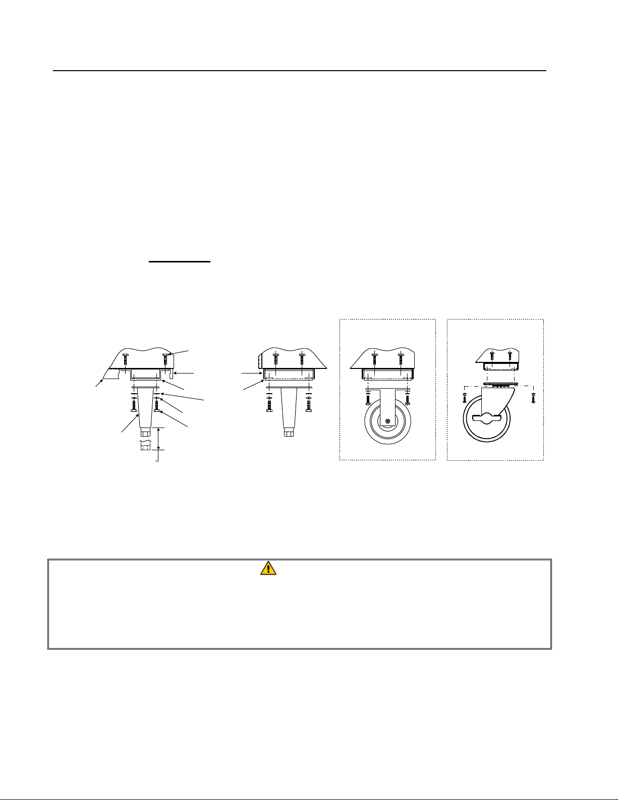
3.3 Installing Casters and Legs
A. Install casters and/or legs near where the fryer is to be used, as neither is secure for long
transit. BID80 Series gas fryers cannot be curb mounted and must be equipped with either
legs or casters provided.
B. After unpacking, use a pallet or lift jack to raise the unit before installing the casters.
C. Align the caster or leg base holes with the leg support assembly and insert bolt. Install the
washers and nut hand tight, and repeat for all four holes in caster/leg base assembly.
D. Tighten the caster/leg against the leg support assembly by using appropriate tools. Ensure
that all four bolts are evenly tightened.
E. For fryers with casters, there are no built-in leveling devices. The floor where the fryers
are installed must be level.
Front Channel
or Rear Channel
Front or Rear Leg with
Mounting Plate
Front View
Adjust as needed
1/4-20 x 3/4 Hex Bolt
Front Channel or
Rear Channel
Leg Support Assembly
Washer
1/4-20 Hex Head Locknut
1/4-20 x 3/4 Hex Bolt
Rear Side View
Optional Caster-
Rear Only
Rear Caster—5" Rigid
Optional Caster-
Front Only
Front Caster—5" Swivel
w/Brake
Caster/Leg Installation and Adjustment
WARNING
Frymaster fryers equipped with legs are for permanent installations. Fryers fitted
with legs must be lifted during movement to avoid damage and possible bodily
injury. For a moveable or portable installation, Frymaster optional equipment casters
must be used.
Questions? Call 1-800-551-8633
3-2
Page 14
BID80 SERIES GAS FRYERS
CHAPTER 3: INSTALLATION
3.4 Gas Connections
A. The gas supply (service) line must be the same size or greater than the fryer inlet line. This
fryer is equipped with a 3/4" (19 mm) male inlet. The gas supply line must be sized to
accommodate all the gas-fired equipment that may be connected to that gas supply. Consult
your contractor, gas company, supplier, or other knowledgeable authorities.
Recommended Gas Supply Line Sizes
Gas Types Number of Fryers
1 2 to 3 4 or more (*)
Natural Gas 3/4" (19 mm) 1" (25 mm) 1 1/4" (33 mm)
Propane Gas 1/2" (13 mm) 3/4" (19 mm) 1" (25 mm)
(*) When exceeding 18 feet (6 meters) for a configuration of more than four fryers, it is necessary
to provide a 1 1/4" (33 mm) rigid gas connection.
CAUTION
All connections must be sealed with a joint compound suitable for the gas being
used, and all connections must be tested with a soapy solution before lighting any
pilots.
B. Rigid Connections: Check any installer-supplied intake pipe(s) visually and clean threading
chips, or any other foreign matter before installing into a service line. If the intake pipes are
not clear of all foreign matter, the orifices will clog when gas pressure is applied. Seal pipe
joints with a sealant resistive to LP gas. When using thread compound on gas piping, use
very small amounts and only on male threads. Use a pipe thread compound that is not
affected by the chemical action of LP gases. DO NOT apply thread compound to the first
two pipe threads—doing so will cause clogging of the burner orifices and control valve.
C. Manual shut-off valve : This gas service supplier-installed valve must be installed in the gas
service line ahead of the fryers in the gas stream and in a position where it can be reached
quickly in the event of an emergency.
D. Regulating Gas Pressure: The fryer and shut-off valve must be disconnected from the gas
supply during any pressure testing of the system.
1. External gas regulators are not normally required on this fryer. A safety control valve
protects the fryer against pressure fluctuations. If the incoming pressure is in excess of
½" PSI (3.45 kPa/35 mbar), a step-down regulator will be required.
3-3
Page 15

BID80 SERIES GAS FRYERS
CHAPTER 3: INSTALLATION
3.4 Gas Connections (cont.)
CAUTION
The fryer must be isolated from the gas supply piping system by closing its
individual manual shut-off valve during any pressure testing of the gas supply piping
system at pressures equal to or less than ½ PSI (3.45 kPa/35 mbar).
The fryer and its individual shut-off valve must be disconnected from the gas supply
piping system during any pressure testing of the gas supply system at test
pressures in excess of ½ PSI (3.45 kPa/35 mbar).
E. Manifold Pressure: Only qualified personnel should check the manifold pressure with a
manometer.
1. Check the rating plate for manifold gas pressures. Natural gas units normally require 4"
W.C., and propane units normally require 11" W.C. gas pressure.
2. Double check the arrow forged into the bottom of the regulator body, which shows gas
flow direction. It should point downstream towards the fryers. The air vent cap is also
part of the regulator and should not be removed.
3. If a vent line from the gas pressure regulator is used, it should be installed in
accordance with local codes or in the absence of local codes, with the National Fuel
Gas Code, ANSI Z223.1-(latest edition).
WARNING
Use a diluted soap solution to find potentially dangerous gas leaks when making
new connections.
F. Regulators can be adjusted in the field, but it is recommended that they not be tampered with
unless the part is known to be out of adjustment or serious pressure fluctuations are found to
exist and can be solved no other way.
G. Only qualified service personnel should make adjustments to the regulators.
H. Orifices: The fryer can be configured to operate on any available gas. The correct safety
control valve, appropriate gas orifices, and pilot burner are installed at the factory. While the
valve can be adjusted in the field, only qualified service personnel should make any
adjustments with the proper test equipment.
3-4
Page 16

BID80 SERIES GAS FRYERS
CHAPTER 3: INSTALLATION
3.4 Gas Connections (cont.)
WARNING
If gas odors are detected, the gas supply must be shut off at the main shut-off valve.
The local gas company or FASC should be contacted immediately to rectify the
problem.
I. Flexible Couplings, Connectors and Casters:
1. If the fryer is to be installed with flexible couplings and/or quick-disconnect fittings, the
installer must use a heavy-duty AGA design-certified commercial flexible connector of
at least 3/4" NPT (with suitable strain reliefs), in compliance with the Standard for
Connectors for Movable Gas Appliances, ANSI Z21.69-(latest edition) and Addenda
Z21.69a-(latest edition). Quick disconnect devices must comply with the Standard for
Quick-Disconnect Devices for Use with Gas Fuel, ANSI Z21.41-(latest edition).
WARNING
Do not attach accessories to this fryer unless fryer is secured from tipping. Personal
injury may result.
2. The fryer must be restrained by means independent of the flexible coupling or
connector in order to limit the movement of the fryer. Clips are located on the back
panel of the fryer for the attachment of restraints.
3. If disconnection of the restraint is necessary, this restraint must be reconnected after the
fryer has been returned to its originally installed position.
J. After hook-up, bleed the gas line of air to ensure that the pilot light will ignite quickly.
K. CE Standards: If the unit is to be installed with flexible coupling, use a commercial flexible
coupling certified as NF D 36123 (or other national standard) or a quick disconnect device
certified NF D 36124 (or other national standard).
3-5
Page 17

BID80 SERIES GAS FRYERS
CHAPTER 3: INSTALLATION
3.5 Electrical Connections
The fryer when installed must be electrically grounded in accordance with local codes, or in the
absence of local codes, with the National Electrical Code, ANSI/NFPA 70-(latest edition).
WARNING
This fryer is equipped with a three-prong (grounding) plug for protection against
shock hazard. It should be plugged directly into a properly grounded, three-prong
receptacle. DO NOT CUT, REMOVE, OR OTHERWISE BYPASS THE GROUNDING
PRONG ON THIS PLUG.
The rating plate and wiring diagram are located inside the front door. The fryer is equipped with a
120VAC single-phase 60-hertz system (Domestic), or 230VAC single-phase 50-hertz system
(International/CE). Do not cut or remove the ground prong from the power cord plug. Do not
attempt to use the fryer during a power outage.
3-6
Page 18

BID80 SERIES GAS FRYERS
CHAPTER 4: FRYER OPERATIONS
4.1 Initial Start-up
A. Cleaning: New units are wiped clean with solvents at the factory to remove any visible signs
of dirt, oil, grease, etc. remaining from the manufacturing process, then coated lightly with
oil. Before any food preparation, wash thoroughly with hot, soapy water to remove any film
residue and dust or debris then rinse out and wipe dry. Also wash any accessories shipped
with the unit. Close the drain valve completely and remove the crumb screen covering the
heating tubes. Ensure the screws holding the thermostat and high-limit control sensing bulbs
into the vessel are tight.
CAUTION
Do not bang fry baskets or other utensils on the fryer’s joiner strip (if applicable).
The strip is present to seal the joint between the fry vessels. Banging fry baskets on
the strip to dislodge shortening will distort the strip, adversely affecting its fit. It is
designed for a tight fit and should only be removed for cleaning.
4.1.2 Pilot Lighting Procedures, Electronic Ignition Systems
WARNING
When checking for burner ignition or performance, do not get too close to the
burners. Slow ignition can cause possible flashback, increasing the potential for
facial and body burns.
WARNING
Never use a match or taper to light pilot on this ignition system.
1. Turn gas "ON".
2. Turn electric power "ON" with the appropriate rocker switch or controller/computer.
3. The electric module will turn on the pilot gas supply and the electric ignition spark. The
spark will ignite the pilot gas. The presence of the pilot flame is then proved by the
electric flame sensor, which in turn allows the main gas supply to be turned on. The
operating thermostat or computer/controller controls the fryer after ignition.
WARNING
In the event of prolonged power failure, the ignition module will shut down and lock
out the system. Turn the unit power "OFF" and them back "ON" after power has
been re-established.
4-1
Page 19

BID80 SERIES GAS FRYERS
CHAPTER 4: FRYER OPERATIONS
4.1.2 Pilot Lighting Procedures
4. If the pilot flame fails, the ignition module will shut down and lock out the system. To
restart, turn the electric power "OFF", wait approximately 5 minutes for the system to
recycle itself, then turn the power "ON" again. Repeat Steps 1-3.
4.2 Boil-Out Procedure
CAUTION
Do not leave fryer unattended. The boil-out solution may foam and overflow if fryer is
left unattended. Press ON/OFF switch to the "OFF" position to control this condition.
CAUTION
Water or boil-out solution MUST not be allowed to drain into the filter pan or filter
system. Irreversible damage will result if water is allowed into the system, and all
applicable warranties will be voided.
CAUTION
All drops of water MUST be removed from fry vessel before filling with cooking oil.
Do not turn fryer on to dry…extensive damage will occur to fry vessel and burner
tubes, and ALL applicable warranties will be voided.
A. Before switching the fryer(s) "ON", close the fry-vessel drain-valve(s). Fill the empty fry
vessel with a mixture of cold water and boil-out solution. Follow instructions when mixing.
B. To program computer for Boil Feature, press either switch.
C. Press the switch. will appear in the left display.
D. Enter
temperature is automatically set for 195°F (91°C). The fryer will attain this temperature and
remain there until either switch is pressed, which cancels the boil-out mode. In highaltitude locations, constantly monitor the fryer for over boil. If over-boil occurs, turn off
fryer immediately, allow to cool, and re-enter boil-out mode to continue the boil-out
operation.
(1 6 5 3) in that sequence. The right display will read . The
4-2
Page 20

BID80 SERIES GAS FRYERS
CHAPTER 4: FRYER OPERATIONS
4.2 Boil-Out Procedure (cont.)
E. The burners will heat the boil-out solution to a simmer. Simmer the solution for
approximately 45 minutes. Wearing protective gloves, scrub the sides of the fry vessel and
the tubes with the L-shaped Teflon brush, being careful not to disturb the temperature
sensing probes and the high-limit thermostat.
F. Do not allow the water level to decrease below the bottom OIL LEVEL line in fry vessel
during boil-out operation.
G. After boil out is complete, press the switch to turn fryer off, and then drain the solution
from the fry vessel. Place a metal pan or bucket under the drain port to collect the water
from the fry vessel. DO NOT ALLOW BOIL-OUT SOLUTION TO DRAIN INTO FILTER
PAN!
H. Close the drain, add fresh water (without boil-out solution) and wash all surfaces of the fry
vessel. Drain again.
I. Refill the fry vessel with fresh water and vinegar to neutralize any residual boil-out solution.
Wash all surfaces of the fry vessel. Drain completely and wipe down all surfaces of the fry
vessel to completely eliminate water from the vessel.
4.3 Final Preparation
WARNING
Do not go near the area directly over the flue outlet while the fryer is operating.
Always wear oil-proof, insulated gloves when working with the fryer filled with hot
oil.
Always drain hot oil into a metal container. Hot oil can melt plastic buckets and
crack glass containers.
WARNING
NEVER set a complete block of solid shortening on top of the heating tubes. To do
so will damage the heating tubes and fry vessel, and void the warranty.
A. When using a liquid shortening (cooking oil), fill the fryer to the bottom OIL LEVEL line
scribed into the back of the fryer vessel.
4-3
Page 21

BID80 SERIES GAS FRYERS
CHAPTER 4: FRYER OPERATIONS
4.3 Final Preparation (cont.)
B. When using a solid shortening, first melt it in a suitable container, or cut it into small pieces
and pack it below the heat tubes, between the tubes and on top of the tubes, leaving no air
spaces around the tubes. Do not disturb or bend the sensing bulbs. Never set a complete
block of solid shortening on top of the heating tubes. To do so will damage the heating
tubes and frypot, and void the warranty.
C. Press the switch to turn fryer on. The burners will initially operate in the MELT CYCLE
mode until the shortening reaches 180°F (82°C). It will then automatically switch to normal
operation.
D. When the fry vessel is filled and the shortening is melted, carefully replace the frypot crumb
screen over the heat tubes. Wear oil-proof insulated gloves to avoid the potential for burn
injury when replacing crumb screen.
E. Before starting operation, program the computer to the probable working temperature and
wait for the temperature to stabilize.
4-4
Page 22

BID80 SERIES GAS FRYERS
CHAPTER 5: BUILT-IN FILTRATION
WARNING
Drawings and photos used in this manual are intended to illustrate operational,
cleaning and technical procedures and may not conform to on-site management
operational procedures.
5.1 General
Frymaster BID80 Series fryers come equipped with a built-in filtration system. Photos used in the
procedural illustrations may differ slightly from the filter unit that came with the frying system. The
following procedures apply to all BID80 Series fryers equipped with built-in filter systems.
Typical built-in filter
installed in a single
fryer unit.
5-1
Page 23

BID80 SERIES GAS FRYERS
CHAPTER 5: BUILT-IN FILTRATION
5.2 Filtration Preparation
On initial installation and before each use, remove all loose parts from the filter, wash the filter pan
and all accessories in hot, soapy water and dry thoroughly.
5.2.1 Assembling the Filter
The BID80 Series filter system uses filter paper held in place by a hold-down ring to filter impurities
and debris from the cooking medium. The filter pan is assembled with the following components
(see illustration below):
1. Filter pan.
2. Filter support grid.
3. Filter paper.
4. Hold-down ring.
5. Crumb screen.
6. Rear pan cover.
7. Front pan cover.
7
6
5
4
3
2
5-2
1
Page 24

BID80 SERIES GAS FRYERS
Hold-down ring positioned correctly over filter
CHAPTER 5: BUILT-IN FILTRATION
5.2.1 Assembling the Filter (cont.)
Assemble the filter as follows:
1. Place the support grid in the bottom of filter
pan.
Support grid properly placed in filter pan.
2. Put one filter paper sheet on top of the
support grid. Be sure the paper covers the
filter pan bottom and laps two inches onto the
pan wall.
3. Position the hold-down ring on top of the
filter paper. Ensure the hold-down ring seals
around the support grid. This prevents air
from getting into the system.
Ensure filter paper overlaps two inches on all
sides and is evenly distributed under the holddown ring.
paper in filter pan.
5-3
Page 25

BID80 SERIES GAS FRYERS
CHAPTER 5: BUILT-IN FILTRATION
5.2.1 Assembling the Filter (cont.)
4. Sprinkle 8 ounces of filter powder on the
filter sheet. Ensure the powder covers the
filter paper evenly.
Sprinkle the proper amount of filter powder evenly
over the paper.
5. Place the crumb screen in the filter pan.
Allow the crumb screen to rest on the top
edges of the hold-down ring.
6. Place filter pan covers (2) onto the filter pan
assembly. Ensure the front cover is correctly
positioned over the slip fitting.
Crumb screen properly placed.
Fully assembled pan with proper placement of lid
over slip fitting.
5-4
Page 26

BID80 SERIES GAS FRYERS
CHAPTER 5: BUILT-IN FILTRATION
5.2.2 Installing the Filter
Slide the filter inside the fryer cabinet. Ensure
the male-female slip-fitting coupling is fully
engaged.
The filter pan slides under the fryer (left),
connecting with a slip fitting (right). Slip fitting
location will vary (above or to the side of the
filter pan), according to fryer system.
5.3 Daily Filtration Operation
WARNING
Use caution and wear proper protective clothing. The oil to be filtered is at or near
350°F (177°C). Ensure all hoses are connected properly and drain handles are in
their proper position prior to operating any switches or valves. Failure to do this can
result in severe burns.
WARNING
Drawings and photos used in this manual are intended to illustrate operational,
cleaning and technical procedures and may not conform to on-site management
operational procedures.
5.3.1 General Overview
The filter pump is turned on only after the shortening/oil is brought to operating temperature and
drained into the prepared filter pan. The filter motor is then engaged and oil is drawn through filter
paper and pumped back into the fry vessel. The fry vessel’s drain remains open during the filtering
process. Allow the oil to cycle through the filter paper for approximately 5 minutes. At the end of 5
minutes, close the drain valve and allow the pump to fill the fry vessel to the top OIL LEVEL line.
Leave the pump running for 10-15 seconds after bubbles appear in the fry vessel to ensure all
shortening/oil is pumped from the drain pan and the lines.
5-5
Page 27

BID80 SERIES GAS FRYERS
CHAPTER 5: BUILT-IN FILTRATION
5.3.2 Filtering Tools
Assemble tools to be used for filtering. These are supplied with the filter starter kit included with
the fryer/filter system:
• Frypot/Filter Brush - used to clean frypot and filter pan sides and bottom, heating elements,
and to dislodge sediment during filtration or shortening/oil change.
• Clean-Out Rod (design may vary)- used to dislodge heavy debris in the drain tube (when
needed).
• Filter Powder.
• Filter Paper.
The following tools are not required, but are recommended to make the filtering task easier.
• Measuring Cup - used to measure filter powder.
• Stainless Steel Crumb Scoop – for removing large debris from shortening/oil prior to
filtering.
Note: Always wear oil-resistant, insulated gloves and/or protective gear when
working with hot oil.
5.4 Operating the Filter
5.4.1 Pan Preparation
See Section 5.2.1– Assembling the Filter, and Section 5.2.2– Installing the Filter
5-6
Page 28

BID80 SERIES GAS FRYERS
CHAPTER 5: BUILT-IN FILTRATION
5.4.2 Filter Operation
CAUTION
NEVER operate the filter unit unless cooking oil/shortening is at operating
temperature [~350°F (~177°C)].
1. Turn the fryer off. Ensure the filter pan assembly is prepared as described in Section 5.2.1–
Assembling the Filter.
2. Remove fry baskets from frypot. Prior to
filtering, skim any large debris from the
shortening/oil. Use extreme caution, as
shortening/oil is at or near operating
temperature [~350°F (~177°C)].
3. Remove the support grid from the frypot
using the clean-out rod. Stir the oil with the
L-shaped Teflon brush to suspend debris
prior to draining.
Prior to filtering, skim any large debris from oil in
frypot.
Removing support grid from fry vessel prior to
filtering.
5-7
Page 29

BID80 SERIES GAS FRYERS
CHAPTER 5: BUILT-IN FILTRATION
4. After ensuring the filter pan is correctly
positioned under the drain tube, and the
disconnect is properly connected, pull the red
handle to drain the frypot into the filter pan.
Pull the red handle to open the drain valve.
5. After all oil/shortening has drained from the
frypot into the filter pan, pull the yellow
handle to open the oil return line and activate
the filter pump.
Pull the yellow handle to open the oil return valve
and activate the filter pump.
5-8
Page 30

BID80 SERIES GAS FRYERS
which increases the life of the oil.
CHAPTER 5: BUILT-IN FILTRATION
5.4.2 Filter Operation (cont.)
6. Oil will begin to pump from the filter pan
into the frypot. If the frypot tubes, sides and
bottom have sediment deposits, clean the
frypot with the cleaning brush included with
the fryer. Clean beneath and under the burner
tubes, using care not to disturb the probes
(arrow). Probe location will vary according
to fryer system.
Clean all sediment and suspended particles from
the burner tubes and frypot as the oil begins to
circulate. Use care not to disturb the probes
(arrow) on the burner tube.
7. Allow the oil to circulate for approximately 5
minutes (process known as "polishing") to
remove suspended particles.
8. After the filter cycle is complete, close the
drain valve (push the red handle until it stops)
and allow the fryer to refill (see this section,
Step #4 for additional reference).
Polishing the oil removes suspended particles,
After filtering is complete, close the red drain
handle to start refilling the frypot.
5-9
Page 31

BID80 SERIES GAS FRYERS
CHAPTER 5: BUILT-IN FILTRATION
5.4.2 Filter Operation (cont.)
9. After all oil is pumped back into the frypot,
bubbles will form, indicating air in the oil
return lines. Allow the oil to bubble for 1015 seconds to ensure all shortening/oil is
evacuated from the return lines. Push the
yellow handle to close the oil return valve
and deactivate the filter pump (see this
section, Step #5 for additional reference).
10. If the oil level is low, add oil until the level is
at the top OIL LEVEL line.
Allow the shortening/oil to bubble for 10-15
seconds to ensure evacuation of all shortening/oil
in the return lines.
11. Replace the frypot grid, using care not to
splash hot oil. Turn the fryer on.
Add oil/shortening until the oil level is at the top
OIL LEVEL line. DO NOT OVERFILL THE
FRYPOT.
Replace the frypot grid, using care not to splash
hot oil.
5-10
Page 32

BID80 SERIES GAS FRYERS
fire-proof
CHAPTER 5: BUILT-IN FILTRATION
5.4.2 Filter Operation (cont.)
12. Do not allow crumbs to accumulate in the
crumb tray. The crumb tray MUST be
emptied into a fireproof container at the end
of frying operations EACH day (see
CAUTION statement below).
Empty the filter pan crumb tray into a
container at the end of frying operations each day.
DO NOT ALLOW CRUMBS TO ACCUMULATE IN
TRAY.
CAUTION
The crumb tray in fryers equipped with a filter system must be emptied into a
fireproof container at the end of frying operations each day. Some food particles
can spontaneously combust if left soaking in certain shortening material.
CAUTION
Do not bang fry baskets or other utensils on the fryer’s joiner strip. The strip is
present to seal the joint between the fry vessels. Banging fry baskets on the strip to
dislodge shortening will distort the strip, adversely affecting its fit. It is designed for
a tight fit and should only be removed for cleaning.
5-11
Page 33

BID80 SERIES GAS FRYERS
CHAPTER 6: COMPUTER OPERATION
6.1 Operating Fryers with Computer Magic III.5 Computers
1
6
3
8
5
7
24
ITEM DESCRIPTION
1 Lighted Display — left display of various functions and operations.
2 Lighted Display — right display of various functions and operations.
3 Program Lock and Temperature Check Switch — locks program in
computer and/or displays frypot temperature when depressed.
4/5 Power Switches — either switch turns power "ON" or "OFF".
6/7 Product and Coding Switches — provides access to computer and
programming functions.
8 Programming Switch — used when reprogramming the computer
memory.
WARNING
Before turning on computer, ensure the fryer is filled with cooking oil/shortening or
water. NEVER allow water to enter the Filtration System (if applicable).
6–1
Page 34

BID80 SERIES GAS FRYERS
CHAPTER 6: COMPUTER OPERATION
6.1.1 Equipment Setup and Shutdown Procedures
Setup
WARNING
Fill the frypot to the bottom OIL LEVEL line with vegetable oil before pressing the
ON/OFF switch to the "ON" position. Failure to do so could damage the frypot.
1. Fill the frypot with vegetable oil to the bottom OIL LEVEL line located on the rear of the frypot.
This will allow for oil expansion as heat is applied. Do not fill cold oil any higher than the
bottom line; overflow may occur as heat expands the oil. If solid shortening is used, pack solid
shortening into the cool-zone of the frypot. Continue to pack shortening in frypot to the bottom
OIL LEVEL line.
2. Ensure that the power cord(s) is/are plugged into the appropriate receptacle(s). Verify that the
face of the plug is flush with the outlet plate, with no portion of the prongs visible.
3. Ensure that the vegetable oil level is at the top OIL LEVEL line when the vegetable oil is at its
programmed cooking temperature. It may be necessary to add vegetable oil to bring the level up
to the proper mark, after the oil has reached the programmed cooking temperature. If solid
shortening is used, the MELT cycle MUST be used to melt the shortening. It may be necessary
to add solid shortening to bring the level up to the proper mark after the packed shortening has
melted. DO NOT DISABLE OR CANCEL THE MELT CYCLE UNTIL ALL SOLID
SHORTENING HAS MELTED.
Shutdown
1. Press the ON/OFF switch to the "OFF" position (the display will show "OFF").
2. Filter vegetable oil (if applicable) and clean fryers. See Chapter 7.
3. Place the frypot covers on frypots.
Operating the Fryer
A. Turn the computer on by pressing the switch.
1. One of the following displays will appear:
a. , indicating that the burners are operating in the melt-cycle mode. Fryer will
remain in the melt-cycle mode until it reaches 180°F (82°C) or is canceled manually.
b. , indicating that the pot temperature is 21°F (12°C) or higher than the setpoint.
c. , indicating that the pot temperature is 21°F (12°C) or lower than the setpoint.
6–2
Page 35

BID80 SERIES GAS FRYERS
CHAPTER 6: COMPUTER OPERATION
6.1.1 Equipment Setup and Shutdown Procedures (cont.)
d. " " indicating that the fryer temperature is in the cooking range. NOTE: For best
results, do not cook product until the display reads " ".
e. , indicates a heating problem.
f. , indicates that the pot temperature is more than 410°F (210°C) [395°F (202°C) for
CE (European Community) fryers].
g. , indicates that the computer has detected a problem in the temperature measuring
circuits, including probe.
NOTE: "." decimal point between digits 1 and 2 in either display area indicates that the burners are
on.
B. Melt-Cycle Cancel Feature (built-in computers only).
CAUTION
Do not cancel the melt cycle mode if using solid shortening.
The computer will display during melt-cycle operation. To cancel melt cycle on a full pot,
depress the "R" button . To cancel the melt cycle on a split pot, use the "L" button for leftside pot and the "R" button for right-side pot. will be replaced by . The decimal point
between digits 1 and 2 will illuminate indicating that the burners are on.
C. Cook-cycle operation is initiated by pressing the product switch:
1. The basket lift (on fryers so equipped) will lower the product into the cooking oil/
shortening.
2. The display will indicate the programmed cook time and begin countdown.
3. If shake time is programmed, you will be notified to shake the product "X" seconds after the
cook cycle begins (X= amount of time programmed). An alarm will sound and the display
will read
and the product number selected. If no shake time is programmed
will
not appear during the cook cycle.
4. At the end of cooking cycle, an alarm will sound; will be displayed and the
associated product switch indicator will flash. To cancel the cook alarm, press the flashing
product switch.
6–3
Page 36

BID80 SERIES GAS FRYERS
CHAPTER 6: COMPUTER OPERATION
6.1.1 Equipment Setup and Shutdown Procedures (cont.)
5. At this time, the hold time will be displayed (if programmed greater than 0) and countdown
will begin. When the hold time counter reaches 0, an alarm will sound.
and the
product number selected is displayed. The hold alarm is canceled by pushing the switch.
If display is in use, hold time will count down invisibly until display is free.
6.1.2 Checking Temperature
A. Check the cooking oil/shortening temperature at any time by pressing the switch once.
Check the setpoint by pressing the switch twice.
B. During the idle periods, when the fryer is on but not in use, " " should appear on both
displays on a single frypot computer. " " will appear on the display of the side that is
turned on in a split-vat computer. If not, check actual temperature and setpoint.
C. If you suspect a defective probe, check the cooking oil/shortening temperature with a
thermometer. Insert the thermometer within 1-inch of the vessel-mounted probe. Verify that the
computer readout is within ±5°F (±2°C) of the thermometer reading.
NOTE: The electronic circuitry can be affected adversely by current fluctuations and electrical
storms. If for no apparent reason the computer does not function or program properly, reset the
computer by unplugging the power cord and plugging it back in.
6.2 Programming the Computer Magic III.5 Computer
1. Activate the computer by pressing either switch.
2. To enter the program mode, first press the switch. will appear in the left display. If
you have pressed this switch in error and do not wish to program, press the switch again.
Note: The computer will flash
3. Press
(1 6 5 0) in that sequence to enter the program mode.
4. (Setpoint) will appear in the left display. This is for setting the cooking temperature. The
temperature previously selected will be displayed in the right display. Enter new temperature.
Press the switch to lock in temperature setting. If the setting is correct, press the switch to
cancel the selection.
5. (Select Product) will appear in the left display. Press the product button to be
programmed.
if cooking is in progress.
6. will appear in the left display. The sensitivity number previously selected will be
displayed in the right display. Enter the new desired sensitivity number, the range is 1 to 9.
Enter "0" for no sensitivity. Press the switch to lock in the setting.
6–4
Page 37

BID80 SERIES GAS FRYERS
CHAPTER 6: COMPUTER OPERATION
6.2 Programming the Computer Magic III.5 Computer (cont.)
Sensitivity adjusts computer-cooking time to compensate for the drop in cooking oil/shortening
temperature when a basket of product is placed into the fryer. Sensitivity decreases or
increases cooking time to counterbalance variances in product density, basket-load size, and
initial temperature. A proper sensitivity setting will ensure a high quality product. For example:
4 ounces of fries can be programmed to cook to the same quality as 2 pounds. A good initial
setting is 4 or 5. Some experimenting with the range of 1 to 9 may be required to achieve
optimum quality.
7. will now appear in the left display. A previously entered cook-time will appear in the
right display. If that time is correct, press the switch. If you wish to change the time, enter
the desired time in minutes and seconds. (The new time will be displayed in the left display.)
Press the switch to lock in the setting.
8.
now appears in the left display. The previous shake time (if any) will appear in the right
display. If a product requires shaking during the cooking process, set the shake time by pressing
the number of minutes to cook before shaking. Press the switch to lock in the time. If no
shake time is required, press "0" and press the switch. Example: Total cook time 3:00
minutes, shake after cooking 1:00 minute.
At the end of 1:00 minute, a beeper will sound and the product button indicator will flash for
three seconds.
9.
will now appear in the left display. Set the time to hold the cooked product from 13
seconds to 60 minutes. Press the switch. If you do not wish to use the hold time, enter "0"
and press the switch.
10. will appear in the left display. If you desire to program more products, return to Step 5.
If no more programming is required, lock in program by pressing the switch.
6.2.1 Boil Feature
CAUTION
Do not drain water or boil-out solution into the filtration system (if applicable). Irreparable
damage to the filter system will result and all applicable warranties will be voided.
1. Before switching the fryer "ON", close the frypot drain valve. Fill empty frypot with mixture of
cold water and detergent. Follow detergent instructions when mixing.
NOTE: Boil Mode will not turn on both sides of computer. Each side will have to be turned on
separately.
6–5
Page 38

BID80 SERIES GAS FRYERS
CHAPTER 6: COMPUTER OPERATION
6.2.1 Boil Feature (cont.)
2. To program computer for boil feature, press either switch.
3. Press the switch. will appear in the left display.
4. Enter
(1 6 5 3) in that sequence. The right display will read . The
temperature is automatically set for 195°F (91°C). The fryer will attain this temperature and
remain there until either switch is pressed, which cancels the boil-out mode. In high-altitude
locations, constantly monitor the fryer for over-boil conditions. If over-boil occurs, turn off fryer
immediately, allow to cool, and re-enter boil-out mode to continue the boil-out operation.
SEE CHAPTER 4.2 FOR ADDITIONAL BOIL-OUT PROCEDURES.
6.2.2 Temperature Selection—Fahrenheit to Celsius
1. To change the computer temperature from Fahrenheit to Celsius or Celsius to Fahrenheit, press
either switch.
2. Press the switch. will appear in the left display.
3. Enter
(1 6 5 8) in that sequence. The computer will automatically convert the
temperature from Fahrenheit to Celsius or Celsius to Fahrenheit.
4. Press the switch to display the temperature in the newly selected mode.
6.2.3 Constant Oil Temperature Display Mode
1. To program constant temperature display, press the switch.
2. Press the switch. will appear in the left display.
3. Enter
(1 6 5 L) in that sequence. The cooking oil/shortening temperature will
display constantly in the right display on a full-pot and in both displays on a split-pot.
NOTE: During the product cooking process, the cooking time will not be displayed but timing will
be taking place.
4. To remove the constant oil-temperature display and display the cooking time, repeat Step 2 and
Step 3.
6–6
Page 39

BID80 SERIES GAS FRYERS
CHAPTER 7: PREVENTATIVE MAINTENANCE
7.1 General
Any equipment works better and lasts longer when maintained properly and kept clean. Cooking
equipment is no exception. The BID80 Series gas fryer should be kept clean during the working day
and thoroughly cleaned at the end of each day. Below are recommendations for daily, weekly and
periodic preventative maintenance.
7.1.1 Daily
A. Remove and wash all removable parts.
B. Clean all exterior surfaces of the cabinet. Do not use cleaners, steel wool, or any other
abrasive material on stainless steel.
C. Filter the cooking oil (See Chapter 5) and replace if necessary. The oil should be filtered
more frequently when under heavy use.
7.1.2 Weekly
A. Completely drain the oil from the fryer into a suitable container for disposal. Do not use a
glass or plastic container.
B. Clean the fry-vessel by following boil-out procedures in Chapter 4-2.
CAUTION
Never allow water to boil down and expose the heating tubes. Fry vessel damage
will result.
7.1.3 Periodic
The fryer should be inspected and adjusted periodically by qualified service personnel as part of a
regular kitchen maintenance program.
7-1
Page 40

BID80 SERIES GAS FRYERS
CHAPTER 7: PREVENTATIVE MAINTENANCE
7.1.4 Stainless Steel Care
WARNING
DO NOT let water splash into the tank of hot oil. It will splatter and can cause severe
burns.
All stainless steel fryer cabinet parts should be wiped regularly with hot, soapy water during the day,
and with a liquid cleanser designed for stainless steel at the end of each day.
A. Do not use steel wool, abrasive cloths, cleansers or powders.
B. Do not use a metal knife, spatula or any other metal tool to scrape stainless steel! Scratches
are almost impossible to remove.
C. If it is necessary to scrape the stainless steel to remove any encrusted materials, soak the area
first to soften the deposit, then use a wood or nylon scraper only.
7-2
Page 41

BID80 SERIES GAS FRYERS
CHAPTER 8: TROUBLESHOOTING
8.1 General
CAUTION
This appliance may have more than one power supply connection point. Disconnect
all power cords before servicing.
The problems and possible solutions covered are those most commonly encountered.
To troubleshoot, perform the test set-up at the beginning of each condition. Follow each step in
sequence.
WARNING
Inspection, testing, and repair of gas or electrical equipment should be performed by
qualified personnel.
Use EXTREME CARE when testing Live Electrical Circuits.
8.2 Pilot Burner Malfunction
A. Pilot will not ignite; no evidence of gas at pilot burner.
1. Check that gas valve is open and gas is present at the gas valve.
2. Check pilot burner orifice for dirt or lint.
3. Remove pilot burner gas-supply line and check for contamination; blow out if necessary,
then reinstall.
B. Pilot burner ignites but will not remain lit when gas valve manual knob is released.
1. Check that thermocouple lead is properly screwed into thermocouple connection bushing
on gas valve.
2. Remove end of thermocouple lead from thermocouple connection bushing and clean with
fine sandpaper or emery cloth.
3. Pilot flame may be too high or too low. Adjust pilot flame adjustment screw so that pilot
flame extends about ¾-inch (19-mm) above the top of the pilot burner.
4. Check all connections for cleanliness and security.
8-1
Page 42

BID 80 SERIES GAS FRYERS
CHAPTER 8: TROUBLESHOOTING
8.2 Pilot Burner Malfunction (cont.)
C. Pilot flame of proper size, but is unstable. Flame wavers and does not envelop the
thermocouple completely at all times.
1. Check for drafts that might be caused by air conditioning equipment or make-up air
apparatus. Turn air-moving equipment off and recheck the pilot.
8.3 Main Burner Malfunctions
A. Main burner will not come "ON"; gas not detected at main burner.
1. Check that the gas valve is open.
2. Check that the pilot is ignited and is operating properly.
3. Check the high limit switch for continuity.
4. The combination gas valve may be defective; replace if necessary.
B. Main burner flames are small and appear lazy; shortening does not come up to temperature
quickly.
1. Check gas pressure at the pressure tap of the gas valve. Use dial type or standard water-
type U-gauge manometer. With burner in operation, the pressure should be 4" W.C. (10
mbar) for natural gas, and 11" W.C. (27.5 mbar) for propane.
2. If not, remove the pressure regulator adjustment cover. Use screwdriver to turn the
adjusting screw for proper pressure. Replace cover, re-check pressure and re-install
pressure tap plug.
C. Signs of excessive temperature; shortening scorches and quickly becomes discolored.
1. Check gas pressure as outlined above.
2. Shortening used is of inferior quality and/or shortening has been used too long. Replace
shortening.
3. Ensure vessel is clean when refilling with new shortening.
8-2
Page 43

BID 80 SERIES GAS FRYERS
CHAPTER 8: TROUBLESHOOTING
8.3 Main Burner Malfunctions (cont.)
D. Fryer will not reach the temperature setting and/or runs erratically.
1. Incorrect location of sensor probe or defective temperature sensor.
2. Loose wiring/wire connection
E. Fryer shortening temperature cannot be controlled; fryer runs at high-limit temperature.
1. Defective operating thermostat or temperature probe.
2. Call Service Technician.
8-3
Page 44

BID 80 SERIES GAS FRYERS
CHAPTER 8: TROUBLESHOOTING
8.4 Wiring Diagrams
8.4.1 BID80 Series With Built-In Filtration
IGNITOR
240V
230V
220V
208V
VOLTAGE
WHT
BLK
GND
BOMB
TAIL
BOMB
47C BLK
37C BLK
38C WHT
BLK
WHT
5 AMP
CIRCUIT BREAKER
CB
30C
BRN
SWITCH
BY-PASS
23C BRN
29C BRN
TAIL
39C BLK
21C WHT
5C ORG
WHT
48C
WHT
40C
208VCOM
2 1
24C RED
FUSE
FUSE
FUSE
78
52C BLK
12V
24V
53C BLK
28C BRN
32C ORG
HIGH LIMIT
14C YEL
36C WHT
29C BRN
7C PUR
NC
THERMOSTAT
C
11C RED
15C YEL
31C ORG
16C ORG
35C BLK
T2 T1
NC
R1
6C ORG
BOMB
TAIL
NO
BOMB
24V
COM
46C GRN
TR
GND
IGN
PV/MV
GAS SYSTEM
NC
NO
DRAIN
13C RED
1
1
26C RED
12C PUR
2
2
27C ORG
3 3
9C RED
SWITCH
51C BLK
OPTIONAL DRAIN SWITCH
49C ORG
8C WHT
COM
TAIL
PV
TH
IF USED
4C RED
SEN.
MV
10C PUR
17C RED
SOUND DEVICE
1 2
IGNITION
MODULE
1211
10
3 4 5 6 7 8 9
109 11 12 1 2
532 4 6 7 8
1
18C BLK
1 2
42C BLUE
PV
45C GRN
Controller or
Solid State Digitial
CM III COMPUTER
50C BLK
19C BRN
1211
VD1
PWR
10
RH VAT
3 4 5 6 7 8 9
21
J3
BOARD
109 1211
COMPUTER INTERFACE
532 4 6 7 8
LH VAT
GND
1
J1
NC
NO
3C RED
COM
2C ORG
43C BRN
44C WHT
GAS
MV
VALVE
MV/PV
GRN
1413 1511 12
10
9876543
TO INTERFACE BOARD
21
ALARM
151312 14
10 11986 75
TO COMPUTER
4
321
21C WHT
23C BRN
OIL RETURN
MICRO SWITCH
22C WHT
1 2
1 2
25C GRN
6
BOMB
TAIL
2 3 4 5
54C WHT
1
HEAT TAPE-240V/45 WATT
OPTIONAL HEAT TAPE
MOTOR
T3
HIGH VOLTAGE SHOWN
WHT
32 54
1
GRN
LEADS T5 AND T8 ON THE MOTOR
FOR CHANGE OF ROTATION INTERCHANGE
T26T5T4T8
P1
P2
BRN
8-4
2
2
WHT
1 1
RED
PROBE
Page 45

BID 80 SERIES GAS FRYERS
CHAPTER 8: TROUBLESHOOTING
8.4.2 BID80 Series Interface Board (Enlarged View)
Interface
Board
V1DV2D
J3
RL3
RL4
RL1 PWRPWR
RL2
RL1 = 12VDC 2PST
RL2 = 12VDC SPST (NOT USED)
RL3 = 12VDC 2PST
RL4 = 12VDC SPST (NOT USED)
RIGHT
TEMP
PROBE
24V
C
NC
NO
R2
12V
C
NC
NO
R1
J1
Sound
Device
J3
4
2
F1
10
87
315
7
842J1
Sound:
Terminal #1 - Loud
Terminal #2 - Medium
Terminal #3 - Low
LED 4
R-HEAT
24V
LED 3
LED 5
R-GV
12V
L-GV
To Terminal Tab on
Computer
R
PWR
AIR
LED 6
LED 1
RL-3
V1D
SD
HEAT
3 5 4 13 14 11 J2
1
2
POWER
3 5 4 13 14 11
1
2
POWER
M
T
A
ON/OFF
ON/OFF
LINE
VOLTAGE
LEFT
TEMP
PROBE
Dual Operation Only
LED 2
L-HEAT
6
RL-1
L
PWR
V2D
6
14
14
15
15
A
T
M
8-5
Page 46

9.1 Accessories
BID80 SERIES GAS FRYERS
CHAPTER 9: PARTS LIST
1 2
4 5
ITEM PART # COMPONENT
1 803-0301 Basket, Fry- 6 x 8-¾ x 16-¾ (Optional)
2 810-2122 Grid Assembly, Frypot
3 210-3458 Basket Hanger, D180
4 803-0278 Brush, Teflon- L-Shaped
5 80021 Vat Cover, Frypot (Optional)
3
9-1
Page 47

BID80 SERIES GAS FRYERS
CHAPTER 9: PARTS LIST
9.2 Cabinetry and Related Components
4
3
2
19
5
6
21
18
16
7
1
14
15
17
20
13
2322
12
11
8
9
10
9-2
Page 48

BID80 SERIES GAS FRYERS
CHAPTER 9: PARTS LIST
9.2 Cabinetry and Related Components (cont.)
ITEM PART # COMPONENT
1 211-2532 Side, Cabinet- Left
2 210-1365 Duct, Door Access
3 212-2532 Side, Cabinet- Right
4 200-2683 Back, Cabinet
* 200-1376 Bracket, Restraining
* 200-3635SP Crossbrace, Cabinet Back, Lower
5 823-3512 Flue Cap
6 824-0954 Box, Component (Wireway Control)
7 824-0986 Top Cap
8 200-1301 Pin, Door
9 200-2688 Panel, Inner- Door
* 810-0179 Plug, Handle-Screw Access
* 816-0529 Bumper, Rubber (Self-Adhesive)
* 809-0193 Bushing, Nylon (Door Pin)
10 210-1151 Panel, Outer- Door
11 810-2105 Handle, Chrome (With Screws)
12 810-0066 Magnetic Catch, Door
13 200-3403 Base, Lower Frame
* 200-3461 Cover, Access- Lower Frame Base (2 Required)
14 823-3745 Base, Upper Frame
15 823-3724 Channel, Leg Support (Right and Left)
16 200-3459 Base, Leg Channel
17 210-3588 Slide, Front- Filter Pan
18 823-3751
19 823-3752
20 200-1675 Bracket, Lower Door Hinge
21 210-2870 Plate, Door Magnet
22 810-0356 Caster, Without Brake
23 810-0357 Caster, With Brake
* Not Illustrated
Slide, Rear Left- Filter Pan
Slide, Rear Right- Filter Pan
9-3
Page 49

BID80 SERIES GAS FRYERS
CHAPTER 9: PARTS LIST
9.3 Computer and Related Components
1 2 3
4 5 7
12
13 14
6
11 10
15
8
9
15
16
9-4
Page 50

BID80 SERIES GAS FRYERS
CHAPTER 9: PARTS LIST
9.3 Computer and Related Components (cont.)
ITEM PART # COMPONENT
1 210-3463 Panel, Control- BID80
2 106-2334 Computer, CMIII.5- BID80
3 823-3433 Bezel, Computer
4 807-3611 Relay, 24 Amp (Filter Circuit)
5 807-0979 Transformer, 208/240V - 12V- Secondary
6 807-1999 Transformer, 208/240V – Dual Voltage
7 806-4549 Board, Interface
8 807-0833 Relay, 5 Amp (Latch Relay- Interface Board)
9 806-2071 Harness, Wire- Computer To Interface Board
10 810-1164 Block, Terminal (Power In)
* 816-0217 Insulation, Terminal Block
11 806-7179SP Sound Device
12 807-3680 Thermostat, High-Limit- 450°F Manual Reset
* 810-2046 Spring, Spacer- High-Limit Bulb
13 807-3580 Switch, Rocker- Filter Pump Bypass Switch
14 807-3538 Circuit Breaker, 5 Amp
15 807-1321 Holder, Fuse- Buss Fuse
* 807-3592 Fuse, 2 Amp
16 106-1424 Probe Assembly, Sensor
* 210-1386 Clamp, Probe Bulb and High-Limit Bulb
* 810-2164 Spring, Spacer- Probe Bulb
* 809-0448 Clip, Tinnerman (Sensor Probe and High-Limit Probe Clamp)
* 809-0360 Screw, Probe/H-Limit Bulb Clamp- #8 x 3/8 Slotted Hex Head
* Not Illustrated
9-5
Page 51

BID80 SERIES GAS FRYERS
CHAPTER 9: PARTS LIST
9.4 Drain Valve Components
10
12
7
5
4
6
3
2
9
11
1
13
8
ITEM PART # COMPONENT
1 106-1401 Bracket, Microswitch
2 210-2029 Activator, Microswitch
3 200-1940 Handle, Drain Arm- Push/Pull
4 807-2104 Microswitch
5 809-0842 Nut, Nylock #4-40
6 816-0220 Insulation, Microswitch
7 200-1257 Retainer, Nut- Drain Valve Arm
8 810-2127 Drain Valve, 1-½"
9 200-1269 Guard, Microswitch
10 823-3429 Handle, Drain Valve
11 816-0547 Cap, Handle- Red
12 823-3747 Elbow/Bracket Assembly, Drain Valve
13 813-0784 Drain Nipple- 6"
* Not Illustrated
9-6
Page 52

BID80 SERIES GAS FRYERS
9.5 Filter Pan Components
3
CHAPTER 9: PARTS LIST
6
4
7
2
5
1
ITEM PART # COMPONENT
1 823-3750SP Filter Pan Assembly
* 813-0684 Plug, Hex Socket, 3/8" NPT
* 813-0679 Plug, 1/8" SS Square Head (Female Disconnect)
2 823-3748 Grid, Bottom- Filter Pan
3 803-0289 Paper, Filter- 22 x 34" (100 Sheets)
* 803-0002 Powder, Filter (Carton)
4 823-3742 Ring, Hold-Down (Weighted)
5 823-3736 Basket (Tray), Crumb
6 823-3741 Lid, Pan- Rear
7 823-3739 Lid, Pan- Front
8 810-2141 Caster, 2"- Filter Pan
* Not Illustrated
8
9-7
Page 53

BID80 SERIES GAS FRYERS
CHAPTER 9: PARTS LIST
9.6 Frypot, Burners and Related Components
30
29
1
28
3
2
16
17
18
19
9
7
8
10
22
15
14
11
12
24
15
14
13
20
25
31
26
21
6
5
4
23
27
9-8
Page 54

BID80 SERIES GAS FRYERS
CHAPTER 9: PARTS LIST
9.6 Frypot, Burners and Related Components (cont.)
ITEM PART # COMPONENT
1 823-3396SP Frypot, SS- 1-½" Drain System
2 200-2707 Shield, Heat- Front
3 200-2734 Bracket, Burner Mounting
4 810-2151 Burner, Left
5 810-2149 Burner, Center
6 810-2150 Burner, Right
7 810-2365 Orifice #56 (1.19 mm)
8 810-2072 Manifold, Gas
9 200-1314 Support, Manifold- Left and Right
10 813-0031 Bushing, Hex- ½ to ¾" NPT BM
11 813-0607 Nipple, ½ x 23-½" NPT BM
12 813-0165 Elbow, Street- 90° ½" NPT BM
13 807-3628 Valve, Gas- Honeywell ½ x ¾" 10" W.C.
14 813-0112 Nipple, ¾ x 2" NPT BM
15 813-0066 Elbow, 90° NPT BM
16 813-0635 Nipple, ¾ x 2-¼" NPT BM
17 813-0174 Union, ¾" NPT BM
18 813-0109 Nipple, ¾" x Close NPT BM
19 813-0168 Elbow, Street- 90° ¾" NPT BM
20 813-0359 Coupling, ¾ x 1.62" NPT
21 810-0705 Gas Line, Pilot- One Piece- 23"
22 807-1553 Pilot Assembly, LP
23 807-1310 Sensor, Flame
24 807-1315 Cable, Ignition
25 810-2155 Pilot Burner Assembly, Trailing Pilot-LP
26 810-0703 Gas Line, Trailing Pilot- One Piece- 17-½"
27 810-2138 Valve, Trailing Pilot
28 200-1316 Shield, Flue
29 200-1347 Front, Flue
30 200-1349 Rear, Flue
* 809-0167 Screw, Sheet Metal- 10A x 5/8"
31 823-3513 Diffuser, BID80
* Not Illustrated
9-9
Page 55

BID80 SERIES GAS FRYERS
9.7 Oil Return Components
To Frypot
1
2
5
CHAPTER 9: PARTS LIST
26
24 25
23
2
5
3
6
8
6
10
4
7
9
11
22
21
14
4
11
10
28
2
13
27
4
1
16
12
15
14
13
2
17
18
29
20
19
9-10
Page 56

BID80 SERIES GAS FRYERS
CHAPTER 9: PARTS LIST
9.7 Oil Return Components (cont.)
ITEM PART # COMPONENT
1 813-0460 Nipple, ½ x 3" NPT MB
2 813-0062 Elbow, ½" 90° NPT BM
3 813-0247 Nipple, ½ x 3-½" NPT BM
4 813-0173 Union, ½" NPT BM
5 813-0087 Nipple, ½ x 1-½" NPT BM
6 813-0006 Bushing, ½" to 3/8 NPT BM
7 813-0625 Nipple, 3/8" x Close NPT BM
8 810-2125 Valve, Oil Return- 3/8"
9 813-0644 Nipple, 3/8 x 1-½" NPT BM
10 813-0003 Tee, ½" NPT BM
11 813-0156 Plug, ½" NPT BM
12 813-0247 Nipple, ½ x 3-½" NPT BM
13 813-0165 Elbow, Street- 90° NPT BM
14 813-0022 Nipple, ½" x Close NPT BM
15 813-0265 Nipple, ½ x 2-½" NPT BM
16 813-0661 Nipple, ½ x 2-¼" NPT BM
17 823-3754 Manifold, Suction- Oil Return
18 813-0608 Coupling, ½" x Full NPT BM
19 810-0697 Disconnect, Male- Suction Manifold
20 826-1392 O-Ring, Suction Manifold Disconnect (Qty:5)
21 816-0548 Cap, Handle- Yellow
22 823-3187 Handle, Oil Return
23 823-3344 Handle, Oil Return Arm- Push/Pull
* 809-0885 Washer, 3/8 x 1 x 0.83" Type A Plain
24 202-1233 Bracket, Oil Return Microswitch (RH)
* 826-1389 Screw, ¼-20 x ¾" Hex Head (Qty:10)
* 809-0823 Nut, Nylock- ¼-20
* 809-0825 Nut, Spacer- Kep ¼-20 Hex Head SS
25 200-1341 Bracket, Microswitch Rod
* 826-1371 Screw, Microswitch Rod Bracket (Qty: 25)
26 807-2104 Microswitch, Oil Return
* 809-0846 Screw, 4-40 x 1 Slotted Head- Microswitch
* 826-1366 Nut, 4-40 Keps Hex with External Teeth (Qty: 25)
* 810-2144 Spacer, Aluminum- ¼" O.D. x 3/8"L 4-40
27 810-2100 Motor, 1/3HP 120/230V/50/60Hz
28 810-2252 Pump, Filter- 5GPM
29 807-1419 Strip, Heater- 240V/45W 36"L
* Not Illustrated
9-11
Page 57

Frymaster, L.L.C., 8700 Line Avenue, PO Box 51000, Shreveport, Louisiana 71135-1000
Shipping Address: 8700 Line Avenue, Shreveport, Louisiana 71106
TEL 1-318-865-1711 FAX (Parts) 1-318-219-7140 FAX (Tech Support) 1-318-219-7135
PRINTED IN THE UNITED STATES
SERVICE HOTLINE
1-800-551-8633
Price: $8.00
819-5896
APRIL 2002
 Loading...