

Page 1
Installation, Operation, Service, and Parts Manual
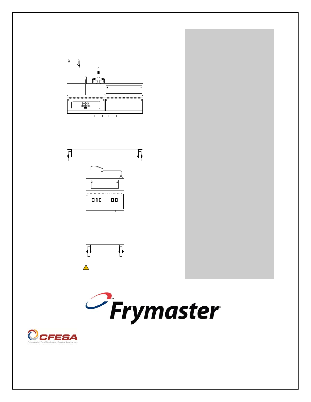
Electric Cooker Models
8SMS, 8BC and 8C
CAUTION
READ THE INSTRUCTIONS BEFORE USING THE
COOKER.
Frymaster, a member of the Commercial Food Equipment Service Association, recommends
using CFESA Certified Technicians.
Original Instructions
24-Hour Service Hotline 1-800-551-8633
*8195246*
04/2015
Page 2
THIS EQUIPMENT IS INTENDED FOR INDOOR USE ONLY.
DO NOT INSTALL OR OPERATE THIS EQUIPMENT IN OUTDOOR AREAS.
DO NOT OPERATE THIS EQUIPMENT WITHOUT FIRST READING THIS MANUAL.
DO NOT OPERATE THIS EQUIPMENT UNLESS ALL COVERS AND ACCESS PANELS ARE IN PLACE AND
PROPERLY SECURED.
DO NOT ATTEMPT TO REPAIR OR REPLACE ANY COMPONENT OF THIS EQUIPMENT UNLESS ALL
POWER TO THE UNIT HAS BEEN DISCONNECTED.
IF THE POWER SUPPLY CORD IS DAMAGED, IT MUST BE REPLACED BY THE MANUFACTURER OR ITS
SERVICE AGENT OR SIMILARLY QUALIFIED PERSONS IN ORDER TO AVOID A HAZARD.
USE CAUTION WHEN SETTING UP, OPERATING, OR CLEANING THIS EQUIPMENT TO AVOID CONTA CT
WITH HEATED SURFACES.
DO NOT USE WATER JETS TO CLEAN THIS EQUIPMENT.
THIS EQUIPMENT IS TO BE INSTALLED IN COMPLIANCE WITH THE BASIC PLUMBING CODE OF THE
BUILDING OFFICIALS AND CODE ADMINISTRATORS INTERNATIONAL, INC. (BOCA ) AND THE FOOD
SERVICE SANITATION MANUAL OF THE FOOD AND DRUG ADMINISTRATION.
DANGER
IMPROPER INSTALLATION, ADJUSTMENT, ALTERATION, SERVICE, OR MAINTENANCE CAN CAUSE
PROPERTY DAMAGE, INJURY, OR DEATH. READ THE INSTALLATION, OPERATING, AND SERVICE
INSTRUCTIONS THOROUGHLY BEFORE INSTALLING OR SERVICING THIS EQUIPMENT.
DANGER
FOR YOUR SAFETY, DO NOT STORE OR USE GASOLINE OR OTHER FLAMMABLE LIQUIDS OR VAPORS
IN THE VICINITY OF THIS OR ANY OTHER APPLIANCE.
COMPUTERS
FCC
This device complies with Part 15 of the FCC rules. Operation is subject to the following two conditions:
1) This device may not cause harmful interference, and 2) This device must accept any interfere nce
received, including interference that may cause undesired operation. While this device is a verified Class
A device, it has been shown to meet the Class B limits.
CANADA
This digital apparatus does not exceed the Class A or B limits for radio noise emissions as set out by the
ICES-003 standard of the Canadian Department of Communications.
Cet appareil numerique n’emet pas de bruits radioelectriques depassany les limites de classe A et B
prescrites dans la norme NMB-003 edictee par le Ministre des Communcations du Canada.
DANGER
THIS PRODUCT CONTAINS CHEMICALS KNOWN TO THE STATE OF CA LIFORNIA TO CAUSE CANCER
AND/OR BIRTH DEFECTS OR OTHER REPRODUCTIVE HARM.
Operation, installation, and servicing of this product could expose you to airborne particles of glasswool
or ceramic fibers, and/or crystalline silica. Inhalation of airborne particles of glasswool or ceramic fibers
is known to the State of California to cause cancer.
FRYMASTER COOKERS EQUIPPED WITH LEGS ARE FOR PERMANENT INSTALLATION. FOR
MOVEABLE OR PORTABLE INSTALLATION, FRYMASTER OPTIONAL EQUIPMENT CASTERS MUST BE
USED.
QUESTIONS??? CALL 1-800-551-8633.
Do not use deliming solution to clean water bath units. Use of deliming solution will damage all stainless
steel parts.
Page 3
CAUTION
Use caution and wear appropriate safety equipment to avoid contact with hot liquids, food or surfaces
that may cause severe burns or injury.
CAUTION
Use caution as the floor may be slippery adjacent to the cooker.
NOTICE
IF, DURING THE WARRANTY PERIOD, THE CUSTOMER USES A PART FOR THIS MANITOWOC EQUIPMENT OTHER
THAN AN UNMODIFIED NEW OR RECYCLED PART PURCHASED DIRECTLY FROM FRYMASTER DEAN, OR ANY OF
ITS AUTHORIZED SERVICERS, AND/OR THE PART BEING USED IS MODIFIED FROM ITS ORIGINAL
CONFIGURATION, THIS WARRANTY WILL BE VOID. FURTHER, FRYMASTER DEAN AND ITS AFFILIATES WILL NOT
BE LIABLE FOR ANY CLAIMS, DAMAGES OR EXPENSES INCURRED BY THE CUSTOMER WHICH ARISE DIRECTLY
OR INDIRECTLY, IN WHOLE OR IN PART, DUE TO THE INSTALLATION OF ANY MODIFIED PART AND/OR PART
RECEIVED FROM AN UNAUTHORIZED SERVICER.
This appliance is intended for professional use only and is to b e operated by qualified personnel only. A Frymaster
DEAN Factory Authorized Servicer (FAS) or other qualified professional should perform installation, maintenance,
and repairs. Installation, maintenance, or repairs by unqualified personnel may void the manufacturer’s warranty.
See Chapter 1 of this manual for definitions of qualified personnel.
The appliance must be installed and used in such a way that any fat or hot oil cannot contact the water.
These instructions are also found online at www.frymaster.com under the Service heading.
NOTICE
NOTICE
NOTICE
DANGER
This appliance must be connected to a pow er supply having the same voltage and phase a s specified on the rating
plate located on the inside of the appliance door.
WARNING
This appliance is not intended for use by persons (including children) with reduced physical, sensory or mental
capabilities, or lack of experience and knowledge, unless they have been given supervision concerning use of the
appliance by a person responsible for their safety. Do not allow children to play with this appliance.
NOTICE
This appliance is intended to be used for commercial applications, for example in kitchens of restaurants, canteens,
hospitals and in commercial enterprises such as bakeries, butcheries, etc., but not for continuous mass production
of food.
DANGER
When installed, this appliance must be electrically grounded in accord ance with local codes, or in the absence of
local codes, with the National Electrical Code, ANSI/NFPA 70, the Canadian Electrical Code, CSA C22.2, or the
appropriate national code of the country in which installed.
ii
Page 4

ELECTRIC COOKERS 8SMS, 8BC AND 8C
TABLE OF CONTENTS
CHAPTER 1: General Information
1.1 Parts Ordering and Service Information .......................................................................... 1-1
1.2 Safety Information ........................................................................................................... 1-1
1.3 Equipment Description .................................................................................................... 1-2
1.4 Installation, Operating, and Service Personnel ................................................................ 1-2
1.5 Definitions........................................................................................................................ 1-3
1.6 Shipping Damage Claim Procedure ................................................................................. 1-3
CHAPTER 2: Installation Instructions
2.1 General Installation Requirements ................................................................................... 2-1
2.2 Caster/Leg Installation ..................................................................................................... 2-3
2.3 Pre-Connection Preparations ........................................................................................... 2-3
2.4 Connecting to the Electrical Power Supply ..................................................................... 2-4
Field Connection Wiring Diagrams ................................................................................. 2-5
CHAPTER 3: Operating Instructions
3.1 Introduction ...................................................................................................................... 3-1
3.2 Operating Instructions ...................................................................................................... 3-2
3.3 Shutting the Cooker Down ............................................................................................... 3-2
3.4 Boiling Out the Cookpot .................................................................................................. 3-3
CHAPTER 4: Preventive Maintenance
4.1 Daily Preventive Maintenance ......................................................................................... 4-1
4.2 SMS II Controller Simmer Mode Adjustment ................................................................. 4-2
CHAPTER 5: Operator Troubleshooting
5.1 Introduction ...................................................................................................................... 5-1
5.2 Operator Troubleshooting Guides .................................................................................... 5-2
5.3 Replacing the Controller or Controller Wiring Harness .................................................. 5-3
5.4 Replacing Fuses ............................................................................................................... 5-4
CHAPTER 6: Service Procedures
6.1 Functional Description of Electric Cookers 8SMS, 8BC, and 8C ................................... 6-1
6.2 Accessing Equipment for Servicing ................................................................................. 6-2
6.3 Replacing Equipment Components.................................................................................. 6-2
6.3.1 Replacing the Controller .................................................................................................. 6-2
6.3.2 Replacing the Transformer, Basket Lift Relay, Contactor, or Solenoid Valve ............... 6-2
6.3.3 Replacing the Element ..................................................................................................... 6-3
6.3.4 Replacing the High-Limit Thermostat ............................................................................. 6-4
6.3.5 Replacing a Water Level Sensor or the Temperature Probe ............................................ 6-5
6.3.6 Replacing the Pressure Regulator .................................................................................... 6-6
6.3.7 Replacing the Water Faucet ............................................................................................. 6-7
6.3.8 Replacing the Cookpot or Rinse Tank ............................................................................. 6-8
6.3.9 Replacing the Basket Lift Motor and Related Components .......................................... 6-10
i
Page 5

6.4 Troubleshooting ............................................................................................................. 6-11
6.4.1 How the Autofill System Works .................................................................................... 6-11
6.4.2 How the Water Heating System Works ......................................................................... 6-11
6.4.3 Technician Troubleshooting Guides .............................................................................. 6-12
Troubleshooting the Autofill System ............................................................................. 6-12
Troubleshooting the Basket Lift .................................................................................... 6-13
Troubleshooting the Controller ...................................................................................... 6-14
Troubleshooting the Contactor Coil............................................................................... 6-15
Troubleshooting the High-Limit Thermostat ................................................................. 6-15
Troubleshooting the Temperature Probe ....................................................................... 6-15
6.5 Wiring Diagrams ............................................................................................................ 6-16
CHAPTER 7: Parts List
7.1 Accessories ...................................................................................................................... 7-1
7.2 Basket Lift Components .................................................................................................. 7-2
7.3 Cabinetry .......................................................................................................................... 7-4
7.4 Cookpot and Rinse Tank Components ............................................................................ 7-6
7.5 Electrical Components and Controllers ............................................................................7.8
7.6 Water Supply Components .............................................................................................. 7-9
APPENDIX A: SERIES CODE HISTORY ................................................................................ A-1
ii
Page 6

ELECTRIC COOKERS 8SMS, 8BC AND 8C
CHAPTER 1: GENERAL INFORMATION
1.1 Parts Ordering and Service Information
In order to assist you as quickly as possible, the Factory Authorized Servicer (FAS) or Service Department representative requires certain information about your equipment. Most of this information is printed on a data plate affixed to the inside of the door.
Parts orders may be placed directly with your local FAS or distributor. A list of Frymaster Factory
Authorized Servicers (FAS’s) is located on the Frymaster website at www.frymaster.com. If you
do not have access to this list, contact the Frymaster Technical Service Department at 1-800-5518633 or 1-318-865-1711.
When ordering parts, the following information is required:
Model Number:
Serial Number:
Voltage:
Item Part Number:
Quantity Needed:
Service information may be obtained by contacting your local FAS/Distributor. Information may
also be obtained by calling the Frymaster Technical Service Department at 1-800-551-8633 or
1-318-865-1711. When requesting service, please have the following information ready:
Model Number:
Serial Number:
Voltage:
In addition to the model number, serial number, and voltage, please be prepared to describe the
nature of the problem and have ready any other information that you think may be helpful in
solving your problem.
RETAIN AND STORE THIS MANUAL IN A SAFE PLACE FOR FUTURE USE.
1.2 Safety Information
Before attempting to operate your unit, read the instructions in this manual thoroughly.
Throughout this manual, you will find safety notations enclosed in boxes similar to the ones
illustrated below and on the following page.
CAUTION
CAUTION boxes contain information about actions or conditions that may cause or result
in malfunction of your equipment.
1-1
Page 7

WARNING
WARNING boxes contain information about actions or conditions that may cause or
result in damage to your equipment, and which may cause your equipment to
malfunction.
DANGER
DANGER boxes contain information about actions or conditions that may cause or result
in injury to personnel, and which may cause damage or malfunctioning of your
equipment
1.3 Equipment Description
Frymaster Electric Cookers are specifically designed to deliver high volumes of cooked or blanched
food automatically.
Model Comparison:
8SMS: The “Spaghetti Magic System” features an 8-kilowatt cooker and rinse tank
combination. The 8.7-gallon (33-liter) cooker is equipped with a programmable computer
that controls water temperature, water level, and cooking times. A swing-away water faucet
is standard. Its automatic basket lift system submerges and extracts either bulk or
individualized portions of pasta according to times programmed by the operator. Options
include automatic water filling (AutoFill) and starch skimming (AutoSkim). The AutoFill
feature maintains the cookpot water level approximately 1¼ inch (32mm) below the
overflow drain. The AutoSkim feature sprays water onto the surface of the water, forcing
starch to the overflow drain. This eliminates loss of cooking time associated with removing
excess starch buildup. It also keeps the cooking water at the optimum level by replacing
water evaporated during the cooking process. The AutoSkim function also saves energy
since there is no need to reheat a refilled cookpot. The cookpot is safeguarded against over
filling and boilover by a large overflow drain. “SD” following the model designation
indicates a stainless steel cookpot and door, and an enameled cabinet. “SC” following the
model designation indicates all stainless steel components.
8BC & 8C: These standalone cookers are essentially the same as the 8SMS, but without
the built-in rinse tank. 8BC models have an automatic basket lift and optional automatic
water filling and starch skimming. 8C models have no basket lifts and no automatic water
filling and starch skimming options. The cookpot in both is safeguarded against over filling
and boilover by a large overflow drain. “SD” following the model designation indicates a
stainless steel cookpot and door, and an enameled cabinet. “SC” following the model
designation indicates all stainless steel components.
1.4 Installation, Operating, and Service Personnel
Operating information for Frymaster equipment is intended for use by qualified and/or authorized
personnel only, as defined in Section 1.5.
All installation and service on Frymaster equipment must be performed by qualified, certified, licensed, and or/authorized installation or service personnel, as defined in Section 1.5.
1-2
Page 8

1.5 Definitions
QUALIFIED AND/OR AUTHORIZED OPERATING PERSONNEL
Qualified/authorized operating personnel are those who have carefully read the information in this
manual and have familiarized themselves with the equipment functions, or who have had previous
experience with the operation of the equipment covered in this manual.
QUALIFIED INSTALLATION PERSONNEL
Qualified installation personnel are individuals, or firms, corporations, or companies that, either in
person or through a representative, are engaged in and are responsible for the installation of
electrical appliances. Qualified personnel must be experienced in such work, be familiar with all
electrical precautions involved, and have complied with all requirements of applicable national and
local codes.
QUALIFIED SERVICE PERSONNEL
Qualified service personnel are those who are familiar with Frymaster equipment and who are
authorized by Frymaster to perform service on Frymaster equipment. All authorized service
personnel are required to maintain a complete set of service and parts manuals and to stock a
prescribed minimum amount of Frymaster parts. Failure to use qualified service personnel will
void the Frymaster Warranty on your equipment.
1.6 Shipping Damage Claim Procedure
Your Frymaster equipment was carefully inspected and packed before leaving the factory. The
transportation company assumes full responsibility for safe delivery upon acceptance of the equipment for transport.
What to do if your equipment arrives damaged:
1. File a claim for damages immediately, regardless of the extent of damages.
2. Inspect for and record all visible loss or damage and ensure that this information is noted on
the freight bill or express receipt and is signed by the person making the delivery.
3. Concealed loss or damage that was unnoticed until the equipment was unpacked should be
recorded and reported to the freight company or carrier immediately upon discovery. A
concealed damage claim must be submitted within 15 days of the date of delivery. Ensure that
the shipping container is retained for inspection.
FRYMASTER DOES NOT ASSUME RESPONSIBILITY
FOR DAMAGE OR LOSS INCURRED IN TRANSIT.
1-3
Page 9
ELECTRIC COOKERS 8SMS, 8BC AND 8C
CHAPTER 2: INSTALLATION INSTRUCTIONS
2.1 General Installation Requirements
Proper installation is essential for the safe, efficient, trouble-free operation of this appliance.
Qualified, licensed, and/or authorized installation or service personnel, as defined in Section
1.5 of this manual, should perform all installation and service on Frymaster equipment.
Failure to use qualified, licensed, and/or authorized installation or service personnel (as de-
fined in Section 1.5 of this manual) to install or otherwise service this equipment will void the
Frymaster warranty and may result in damage to the equipment or injury to personnel.
Where conflicts exist between instructions and information in this manual and local or national codes or regulations, installation and operation shall comply with the codes or regulations in
force in the country in which the equipment is installed.
Service may be obtained by contacting your local Frymaster Authorized Servicer.
NOTICE
All cookers shipped without factory supplied cords and plug assemblies must be
hardwired using flexible conduit to the terminal block located on the rear of the fryer.
These fryers should be wired to NEC specifications. Hardwired units must include
installation of restraint devices.
DANGER
Adequate means must be provided to limit the movement of this appliance without
depending on or transmitting stress to the electrical conduit. A restraint kit is provided with the fryer. If the restraint kit is missing contact your local Frymaster Authorized Servicer (FAS).
NOTICE
If this equipment is wired directly into the electrical power supply, a means for disconnection from the supply having a contact separation of at least 3-mm in all poles
must be incorporated in the fixed wiring.
NOTICE
This equipment must be positioned so that the plug is accessible unless other
means for disconnection from the power supply (e.g., a circuit breaker) is provided.
NOTICE
If this appliance is permanently connected to fixed wiring, it must be connected by
means of copper wires having a temperature rating of not less than 167°F (75°C).
2-1
Page 10

NOTICE
If the electrical power supply cord is damaged, it must be replaced by a Frymaster
Authorized Service Agency technician or a similarly qualified person in order to
avoid a hazard.
Upon arrival, inspect the equipment carefully for visible or concealed damage. (See Shipping
Damage Claim Procedure in Chapter 1.)
NATIONAL CODE REQUIREMENTS
This equipment is to be installed in compliance with the Basic Plumbing Code of the Building
Officials and Code Administrators International, Inc. (BOCA) and the Food Service Sanitation
Manual of the U.S. Food and Drug Administration.
ELECTRICAL GROUNDING REQUIREMENTS
All electrically operated appliances must be grounded in accordance with all applicable national and
local codes and, where applicable, CE codes. All units (cord connected or permanently connected)
should be connected to a grounded power supply system. A wiring diagram is located on the inside
of the equipment door. Refer to the rating plate on the inside of the door for proper voltages.
The equipotential grounding lug allows all the equipment in the same location to be electrically connected to ensure there is no electrical potential difference between the units,
which could be hazardous.
FCC COMPLIANCE
The user is cautioned that any changes or modifications to Frymaster controllers not expressly
approved by the party responsible for compliance could void the user’s authority to operate the
equipment. Frymaster controllers have been tested and found to comply with the limits for a Class
A digital device, pursuant to Part 15 of the FCC rules. While these devices are verified as Class A
devices, they have been shown to meet the Class B limits. These limits are designed to provide
reasonable protection against harmful interference when the equipment is operated in a commercial
environment. This equipment generates, uses, and can radiate radio frequency energy and, if not
installed and used in accordance with the instruction manual, may cause harmful interference to
radio communications. Operation of the equipment in a residential area is likely to cause harmful
interference in which case the user will be required to correct the interference at his own expense.
If necessary, the user should consult the dealer or an experienced radio and television technician for
additional suggestions.
The user may find the booklet “How to Identify and Resolve Radio-TV Interference Problems”
helpful. It is prepared by the Federal Communications Commission and is available from the U.S.
Government Printing Office, Washington, DC 20402, Stock No. 004-000-00345-4.
2-2
Page 11

2.2 Caster/Leg Installation
Depending upon the specific configuration ordered, your unit might have been shipped without installed casters or legs. If casters or legs are installed, you may skip this section and proceed to Section 2.3, Pre-Connection Preparations.
If your unit requires the installation of casters/legs, install them in accordance with the instructions included in your accessory package.
2.3 Pre-Connection Preparations
After the unit has been positioned in the area where it will be used, ensure the following have been
accomplished before connecting the unit to the electrical power source:
1. This equipment must be stabilized by installing restraining chains on units equipped with
casters or anchor straps on units equipped with legs. Follow the instructions shipped with
the casters/legs to properly install the chains or straps.
2. Level units equipped with legs by screwing the legs out approximately 1 inch, then adjusting
them so that the unit is level.
For units equipped with casters, there are no built-in leveling devices. The floor where the
unit is to be installed must be level.
3. Install the basket lift arm (on units so equipped) on the lift rod (located at the top rear of the
cabinet) so that the basket lift roller guides the lift arm.
NOTE: Some adjustment of the roller may be necessary for free movement of the basket lift
arm.
4. Connect the water hose to the fitting at the rear of the unit. A new hose set should be used for
the water connection and any old hoses discarded.
DANGER
The maximum allowable incoming water pressure for all units is 80 PSI (5.6 kg/cm2)
(551.6 kPa).
The maximum allowable incoming water temperature for all units is 180ºF (82ºC).
NOTE: Either hot or cold water may be connected to the unit. However, connecting hot
water will minimize the time required to bring the unit to boil when filling with fresh water.
NOTE: In order for the water level sensors to work properly, a certain amount of mineral
content in necessary in the water. For that reason, purified, deionized, or highly filtered water should not be used.
5. Connect the desired drain plumbing to the drain valve.
2-3
Page 12
2.4 Connecting to the Electrical Power Supply
DANGER
This unit must be connected to the voltage and phase specified on the rating and serial
number plate located on the inside of the equipment door. To determine the appropriate
wire size, refer to the POWER REQUIREMENTS chart at the bottom of this page.
1. If the unit is not equipped with an installed power cord, open the door and remove the contactor
box cover. Position the unit to gain access to the rear and remove the lower back panel.
2. Insert an appropriately rated power cord into the rear of the contactor box and make connections
in accordance with the applicable wiring diagram on the following page. The supply cord must
be oil resistant and not lighter than ordinary polychloroprene (60245 IEC 57). Install a strain relief on the power cord and replace the lower back panel and contactor box cover.
3. Attach a plug that complies with national and/or applicable local codes to the free end of the
electrical power cord and plug the unit into an appropriate outlet.
4. The power plug is the disconnect device and the cord must be accessible when the unit is in-
stalled and operating.
POWER REQUIREMENTS
Use copper wire ONLY, suitable for at least 170ºF (75ºC)
Amps
Volts Phase Watts
200 Single 7400 37 AWG 6 (4.1 mm)
208 Single 8000 39 AWG 6 (4.1 mm)
220 Single 7300 34 AWG 6 (4.1 mm)
230 Single 8000 35 AWG 6 (4.1 mm)
240 Single 8000 34 AWG 6 (4.1 mm)
200 3P – Delta 7400 22 AWG 8 (3.3 mm)
208 3P – Delta 8000 23 AWG 8 (3.3 mm)
220/380 3P – Delta 7300 20 AWG 8 (3.3 mm)
230/400 3P – Delta 8000 21 AWG 8 (3.3 mm)
240/415 3P – Delta 8000 20 AWG 8 (3.3 mm)
200 3P – Wye 7400 13 AWG 8 (3.3 mm)
220/380 3P – Wye 7300 12 AWG 8 (3.3 mm)
230/400 3P – Wye 7400 11 AWG 8 (3.3 mm)
(per leg)
NOTE: This equipment is field-convertible between single phase and three phase.
Minimum
Wire Size
2-4
Page 13
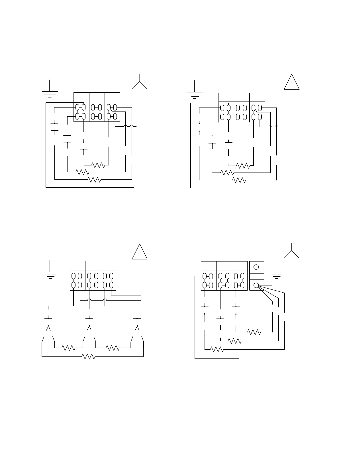
FIELD CONNECTION WIRING DIAGRAMS
1HV
1C1
1
SINGLE PHASE
FIELD CONNECTION
L1
2HV
3HV
1C2
1C3
2
3
L2 L3
4
NEUTRAL TO L3
FROM TRANSFORMER
5
6
FROM TRANSFORMER
1HV
1C1
1
SINGLE PHASE (NO NEUTRAL)
FIELD CONNECTIO N
L2 L3
L1
2HV
3HV
1C2
1C3
2
3
4
FROM
TRANSFORMER
5
6
FROM TRANSFORMER
1HV
1C1
12
3 PHASE 3 WIRE (DELTA)
FIELD CONNECTIO N
L2 L3
L1
2HV
1C2
53
FROM TRANSFORMER
FROM TRANSFORMER
3HV
1C3
46
3 PHASE 4 WIRE (WYE)
FIELD CONNECTION
L2 L3
L1
1HV
1C1
2HV
1C2
1
2
N
3HV
1C3
3
FROM TRANSFORMER
FROM TRANSFORMER
4
5
6
2-5
Page 14
ELECTRIC COOKERS 8SMS, 8BC AND 8C
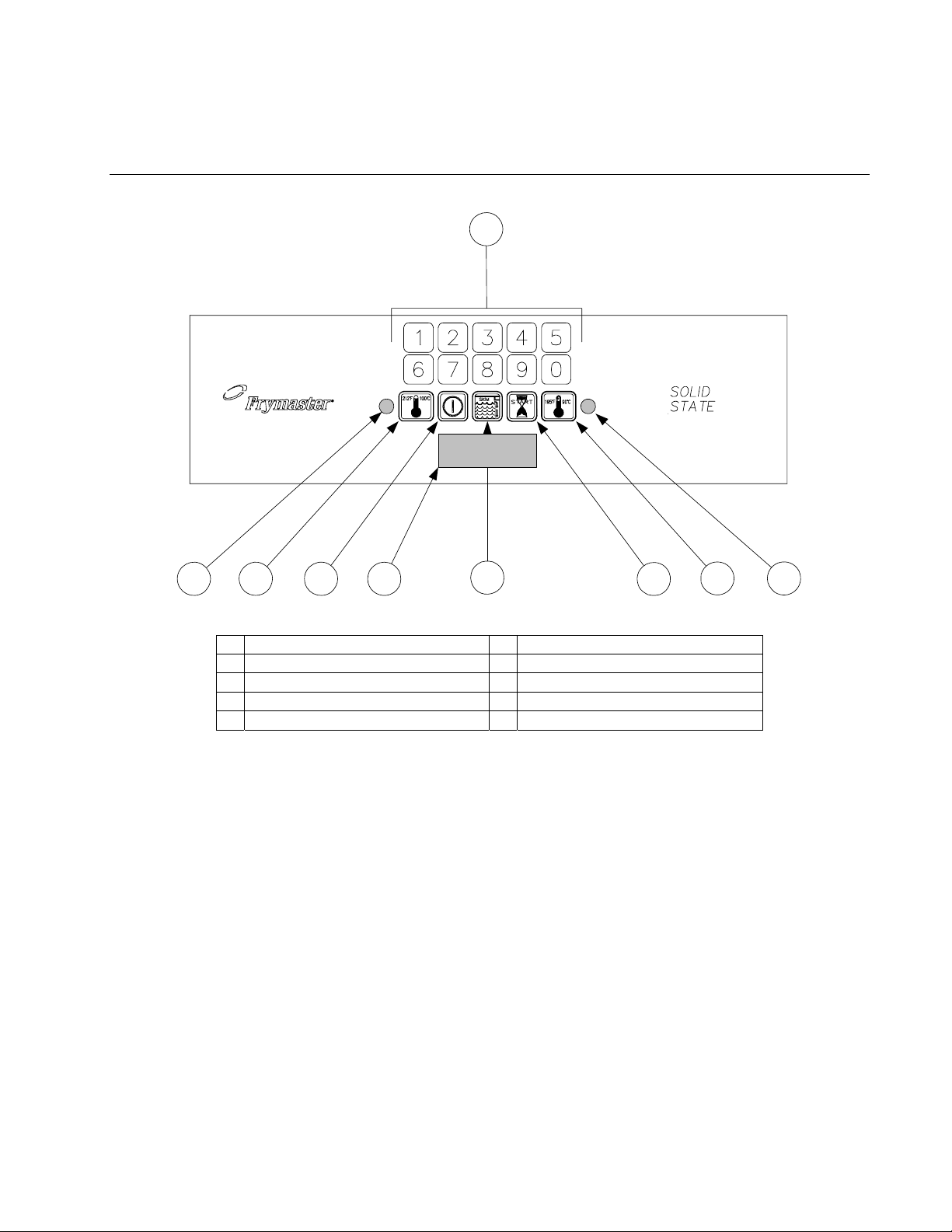
CHAPTER 3: OPERATING INSTRUCTIONS
1
5432 7
1 Numeric Keypad 6 Skim Switch (w/Autoskim only)
2 Boil Mode Indicator 7 Timer Start Switch
3 Boil Mode Switch 8 Simmer Mode Switch
4 Power Switch 9 Simmer Mode Indicator
5 LED Display
6
8 9
3.1 Introduction
The Spaghetti Magic II Controller allows the operator to specify a specific cook time, in minutes and
seconds, then initiate a cooking cycle. This controller is available in three different configurations.
The standard configuration has both automatic filling (Autofill) and automatic skimming (Autoskim)
features. Options include Autofill only, or neither Autofill or Autoskim. On units configured with
the Autoskim feature, the operator may activate or deactivate the feature as desired.
When in the BOIL mode, the heating element is energized at all times. It is used when actually
cooking pasta.
The SIMMER mode feature maintains the water temperature just below boiling, which conserves
energy and water. This feature is designed for rethermalizing previously cooked packaged products,
and for keeping the cooker in standby.
The SKIM feature, when selected, adds water for approximately 3 seconds once a minute. It causes the
water to overflow into the drain, carrying floating starch with it. (A buildup of starch reduces the effi-
3-1
Page 15
ciency of the cooker and can cause erroneous temperature and water level sensing. NOTE: Do not use
deliming solution to clean these units. Use of deliming solution will damage all stainless steel parts.)
LOW WATER SENSING automatically de-energizes the heating element if the water in the cookpot drops too low. When the water level in the cookpot is below the low-water sensor, such as when
draining and cleaning the cookpot, the controller display will read LO.
NORMAL WATER LEVEL SENSING, on units configured with the Autofill feature, automatically
adds water during or after a cooking cycle if the water in the cookpot drops to a level lower than approximately 1¼ inch (32mm) below the overflow drain. With this automatic filling feature, the water level
does not have to be continuously monitored. The cookpot always has the correct amount of water.
3.2 Operating Instructions
Before turning the cooker on, ensure that:
• the unit is connected to the water supply.
• the water supply is turned on.
• the unit is plugged into an appropriate outlet.
• the electrical power supply is turned on.
• only the vessels provided or recommended are used for cooking.
CAUTION
If this is the first time the unit is being used after installation, refer to Section 3.4, Boiling
Out the Cookpot.
1. Turn the controller on by pressing the Power switch.
2. The unit will automatically enter the boil mode and the boil mode indicator will illuminate. If
you do not intend to immediately begin cooking, press the Simmer Mode switch. The simmer mode indicator will illuminate. To re-enter the boil mode, press the Boil Mode switch.
3. Enter the desired cooking time using the numeric keypad. The time entered appears in the LED
display.
4. When ready to initiate a cooking cycle, press the Start Timer switch. The basket lift will au-
tomatically lower the basket or portion cups into the cookpot and the LED display will begin to
count down. At the end of the cooking cycle, an alarm will sound briefly to alert you and the
basket lift will automatically raise the basket or portion cups out of the water.
The display will automatically return to the previously set cooking time. If the same time is desired for the next batch, simply press the Start Timer switch when ready, otherwise enter the
new cooking time before pressing the switch.
5. To initiate the automatic skimming (Autoskim) feature, press the Skim switch.
3-2
Page 16

3.3 Toggling Between Fahrenheit and Celsius Temperature Display
There are two versions of the SMS Controller: one that can be toggled between Fahrenheit and
Celsius temperature display, and one that cannot. To determine which version you have, turn the
controller off by pressing the ON/OFF switch. The display will go blank. Press the Simmer (right
thermometer icon) switch. If Code appears in the display, the temperature display can be changed.
If not, the display cannot be changed.
1. If Code appears in the display, press 1, 6, 5, 8. The display will be toggled from Fahrenheit to
Celsius or from Celsius to Fahrenheit.
2. Press the Boil (left thermometer icon) switch to display the cookpot temperature. If an F follows
the temperature, the display is in Fahrenheit; if a C follows the temperature, the display is in
Celsius.
3.4 Shutting the Cooker Down
Turn the unit off by pressing the Power switch. If shutting down at the end of the day, drain and
clean the cookpot (and rinse tank, if so equipped), and put the cookpot and rinse tank covers in
place.
3.5 Boiling Out the Cookpot
To ensure that the cooker is free of contamination from manufacture, shipping, or handling during
installation, the cookpot must be boiled out before first use.
1. Close the drain valve and fill the cookpot with a solution of cold water and 1 cup of detergent.
2. Place the unit into operation (see Section 3.2).
3. Press the simmer switch and allow the solution to simmer for at least 1 hour.
4. After the solution simmers for 1 hour, turn the unit off and add cold water until the solution is
cool. Drain the solution and clean the cookpot thoroughly with a solution of dishwashing detergent and hot water.
NOTE: Do not use deliming solution to clean these units. Use of deliming solution will damage
all stainless steel parts.
WARNING
When cleaning around the elements, be careful not to bend or otherwise damage the high-
limit thermostat capillary tube.
5. Rinse the cookpot at least twice by filling with clean water and draining. Dry the cookpot tho-
roughly with a clean, dry towel.
6. For units equipped with a rinse tank, clean the tank with a solution of dishwashing detergent and
hot water. Drain the tank and dry it thoroughly with a clean, dry towel.
3-3
Page 17
ELECTRIC COOKERS 8SMS, 8BC AND 8C
CHAPTER 4: PREVENTIVE MAINTENANCE
4.1 Daily Preventive Maintenance
It is normal for a coating of starch to form on the elements, sensors, and temperature probes during
operation. If the coating is allowed to build-up, it will adversely affect the operation of the
equipment. The preventive maintenance routines below should be performed at least daily to keep
your equipment functioning at peak efficiency. The cookpot and rinse tank – especially the waterlevel sensors, temperature probe, and element – may require more frequent cleaning, depending
upon the product and volume. NOTE: Do not use deliming solution to clean these units. Use of
deliming solution will damage all stainless steel parts.
Inspect Equipment and Accessories for Damage
Look for loose or frayed wires and cords, leaks, foreign material in cookpot or inside cabinet,
and any other indications that the equipment and accessories are not ready for safe operation.
Clean Cabinet Inside and Out
Clean inside the cabinet with a dry, clean cloth. Wipe all accessible metal surfaces and
components to remove accumulations of oil, dust, or cooking residue.
Clean the outside of the cabinet with a clean cloth dampened with dishwashing detergent,
removing oil, dust, or cooking residue.
DANGER
Never attempt to clean this equipment during the cooking process or when the
cookpot is filled with hot water and/or food products.
Clean Water-Level Sensors, Temperature Probe, Element, Cookpot, and Rinse Tank
Turn the equipment off and drain the cookpot (and rinse tank, if so equipped).
Remove the probe cover and clean the water-level sensors and temperature probe using a
Scotchbrite™ or similar abrasive pad and a solution of detergent and water.
Using a Scotchbrite™ or similar abrasive pad and a solution of detergent and water, clean the inside
of the cookpot (and rinse tank, if so equipped). Pay particular attention to the heating element.
Rinse the cookpot (and rinse tank, if so equipped) thoroughly with clean water at least twice.
WARNING
Do not use deliming solution to clean these units. Use of deliming solution will
damage all stainless steel parts.
WARNING
When cleaning around the element, be careful not to bend or otherwise damage the
high-limit thermostat capillary tube.
4-1
Page 18

4.2 SMS II Controller Simmer Mode Adjustment
NOTE: The SMS II Controller simmer temperature is adjustable from 185ºF to 215ºF.
1. With the unit in the simmer mode, place the tip of a good grade thermometer near the
temperature probe and determine the actual water temperature in degrees Fahrenheit. If the
temperature is within 5ºF of the desired simmer temperature, nothing more needs to be done. If
it is not within 5ºF of the desired temperature, perform Steps 2 through 5.
2. With the unit in the simmer mode, open the control panel by removing the screws in the upper
corners and tilting the panel out.
3. Remove the black rubber plug from the top of the controller housing.
4. Using a small, flat-tipped screwdriver, turn the adjusting screw to change the simmer setpoint.
¼ turn will change the setpoint about 10ºF. (You will have to experiment with the direction of
rotation to determine which way to turn to raise or lower the temperature.) Wait at least 5
minutes, then recheck actual water temperature. Repeat this step until the water temperature is
within 5ºF of desired temperature.
5. Replace the plug in the controller, close the control panel, and replace the screws removed in
Step 1.
4-2
Page 19

ELECTRIC COOKERS 8SMS, 8BC AND 8C
CHAPTER 5: OPERATOR, TECHNICIAN TROUBLESHOOTING
5.1 Introduction
This chapter provides an easy reference guide to the more common problems that may occur during
the operation of this equipment. The troubleshooting guides in this chapter are intended to help you
correct, or at least accurately diagnose, problems with the equipment. Although the chapter covers
the most common problems reported, you may very well encounter a problem not covered. In such
instances, the Frymaster Technical Service Department will make every effort to help you identify
and resolve the problem.
When troubleshooting a problem, always use a process of elimination starting with the simplest
solution and working through to the most complex. Never overlook the obvious. Anyone can forget
to plug a cord into a receptacle or open the valve on the water supply line. Don’t assume that you
are exempt from such occurrences. Most importantly, try to establish a clear idea of why a problem
has occurred. Part of your corrective action involves taking steps to ensure that it doesn’t happen
again. If a controller malfunctions because of a poor connection, check all other connections while
you’re at it. If a fuse continues to blow, find out why. Keep in mind that failure of a small
component may often be indicative of potential failure or incorrect functioning of a more important
component or system.
Some of the troubleshooting actions recommended in this chapter involve removing suspect
controllers and substituting controllers that are known to be good. This work should only be done by
trained technicians. Whenever this is indicated, refer to Section 5.3. Refer to Section 5.4 for
instructions on replacing fuses.
If you have doubts as to the proper action to take, do not hesitate to call the Frymaster Technical
Service Department or your local Frymaster Factory Authorized Service Center for assistance.
Before calling a servicer or the Frymaster HOTLINE (1-800-551-8633):
• Verify that electrical cords are plugged in and that circuit breakers are on.
• Verify that water supply valves are open and that drain valves are fully closed.
DANGER
Hot water can cause severe burns. Never attempt to move a cooker containing hot
water or to transfer hot water from one container to another.
DANGER
Use extreme care when performing electrical circuit tests. Live circuits will be
exposed.
WARNING
Inspection, testing, and repair of electrical components should be performed only by
qualified service personnel. The equipment should be unplugged when servicing,
except when electrical tests are required.
5-1
Page 20

5.2 Operator Troubleshooting Guides
ON UNIT WITH AUTOFILL,
COOKPOT DID NOT FILL
WHEN UNIT WAS
TURNED ON. WA T ER
SUPPLY TO UNIT
VERIFIED TO BE ON.
Did anything
appear in controller
display when unit was
turned on?
No
Disconnect unit f rom
electrical power. Check
the left 5-amp fus e in
component box. Replace
fuse if blown then attempt
to operate.
Yes
Yes
NOTE: IF AUTOFILL WORKS
BUT AUTOSKIM DOES NOT,
PROBLEM IS A FAILED
CONTROLLER. ORDER
REPLACEMENT FROM FASC
OR DISTRIBUTOR.
Clean the water
level sensors.
Did unit begin
to fill?
No
Did unit begin
to fill?
No
Probable causes are shorted
upper water level sensor, fail ed
water solenoid, or loose/
damaged wiring. Call FASC.
Is another
controller, known
to be working,
available?
No
Problem is beyond
Problem resolved.Yes
the scope of operator
troubleshooting. Call
FASC.
No
Yes
Substitute the c ont roller
known to be working for
the suspect cont roll er and
attempt to operate u ni t .
Did unit begin
to fill?
Yes
Problem is a failed
controller. Order
replacement from
FASC or distributor.
5-2
Page 21

Operator Troubleshooting Guides (Continued)
ON UNIT WITH
AUTOFILL, WATER DID
NOT SHUT OFF WHEN
COOKPOT WAS FULL.
Clean the water
level sensors.
Did the water
stop?
No
Add 1/8-cup of
baking soda to the
water in the
cookpot and stir.
Did the water
stop?
No
Probable causes are a loose or
damaged wire on the upper water
level sensor, a failed water solenoid,
or a failed upper water level sensor.
Call FASC.
Yes
Yes
Problem resolved.
Mineral content of water is
insufficient for water sensor to
ground. Whenever cookpot is
refilled, add 1/8-cup of
baking soda.
5-3
Page 22

Operator Troubleshooting Guides (Continued)
WATER WILL NOT
BOIL. COOKPOT
VERIFIED TO BE FULL
OF WATER WITH BOIL
MODE SELECTED (i.e.,
left indicator is lit).
Is heating
indicator (small
dot in LED)
lit?
No
Is a controller
known to be working
available?
Yes No
Yes
Yes
the suspect controller and
Is water
heating
at all?
Substitute the controller
known to be working for
attempt to operate uni t.
Probable causes are a
failed element, failed contactor,
or loose/damaged wiring.
Call FASC.
No
Problem is beyond the scope
of operator troubleshooting.
Call FASC.
Did water boil?
No
5-4
Yes
Problem is a failed controller.
Order replacement from FASC
or distributor.
Page 23

Operator Troubleshooting Guides (Continued)
WATER BOILS
IN SIMMER
MODE.
Adjust controller in
accordance with
procedure in Chapter 4.
Did boiling
stop?
No
Is a controller
known to be working
available?
No
Problem is beyond the scope
of operator troubleshooting.
Call FASC.
Yes
Problem resolved.Yes
Substitute the controller
known to be working for
the suspect controller and
attempt to operate unit.
Did boiling
stop?
No
Probable cause is a failed/
shorted temperature probe.
Call FASC.
Yes
Problem is a failed controller.
Order replacement from FASC
or distributor.
5-5
Page 24

WATER
TEMPERATURE
IS TOO LOW IN
SIMMER MODE.
Adjust controller in
accordance with
procedure in Chapter 4.
Did water
reach correct
temperature?
Operator Troubleshooting Guides (Continued)
Yes
Problem resolved.
No
Is a controller
known to be working
available?
Yes
Substitute the controller
known to be working fo
the suspect cont roller and
attempt to operate uni t.
No
Did water
reach correct
temperature?
No
Probable cause is open
temperature probe or loose
probe wire. Call FASC.
Yes
Problem is a failed controller.
Order replacement from FASC or
distributor.
5-6
Page 25

Yes
Operator Troubleshooting Guides (Continued)
BASKET LIFT DOES
NOT FUNCTION
CORRECTLY.
Did the
basket lift function
at all?
No
Check the right-side
5-amp fuse. Replace if
blown, then attempt to
operate unit.
Did the
basket lift function
correctly?
No
Does the
basket lift travel
up and down
constantly?
No
If the basket lift works sometimes but not always,
the probable causes are a loose bell crank or a loose
microswitch. Call FASC.
If the movement of the basket lift is jerky or noisy, lubricate
the lifter rod with a light-weight lubricant. if this does not
correct the problem, call FASC.
Yes
Yes
Problem resolved.
Probable causes are a failed
microswitch or a microswitch
that is out of adjustment.
Call FASC.
5-7
Page 26
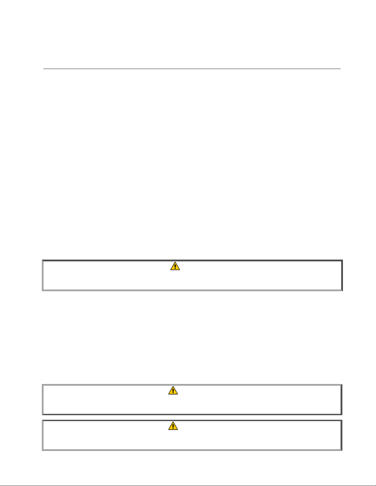
5.3 Replacing the Controller or Controller Wiring Harness
1. Disconnect the cooker from the electrical supply.
2. Remove the two screws in the upper corners of the control panel and swing the panel open
from the top, allowing it to rest on its hinge tabs.
3. Disconnect the wiring harness from the back of the computer.
4. Disconnect the ground wire from the computer. Remove the controller by lifting it from the
hinge slots in the frame.
5. Reverse the procedure to install a new computer or wiring harness.
Wiring Harness
Connection
Ground Wire
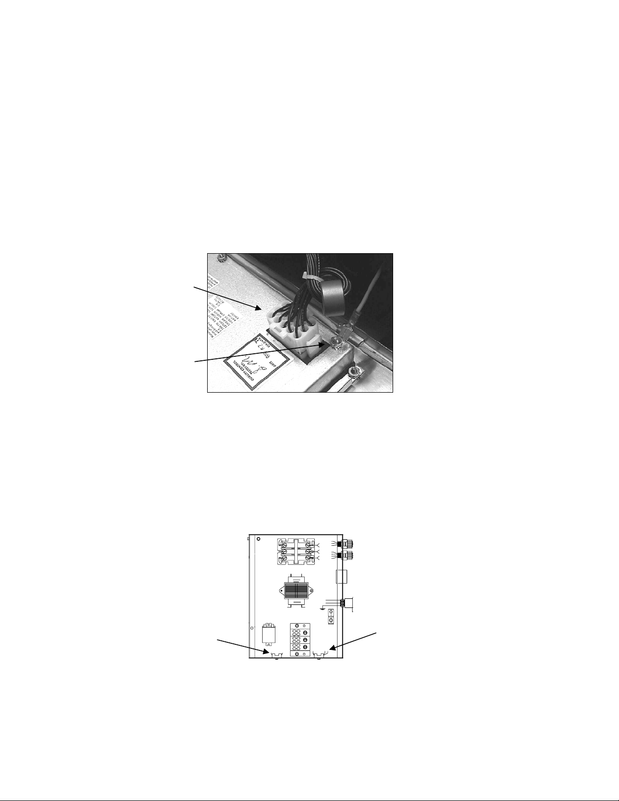
5.4 Replacing Fuses
1. Disconnect unit from electrical power and remove the cover from the contactor box located in
the left front bottom of the cabinet.
2. The 5-amp fuse for the controller is located on the left side of the box. The 5-amp fuse for the
basket lift is located on the right side of the box. Use a fuse puller to remove the blown fuse and
install the replacement.
LOAD
24V
LINE
208/240V
Basket Lift Fuse
Controller Fuse
(Present in 8SMS
and 8BC units only.)
3. Replace the component box cover, being sure to reconnect the ground wire with the upper left
screw.
5-8
Page 27

ELECTRIC COOKERS 8SMS, 8BC AND 8C
CHAPTER 6: SERVICE PROCEDURES
6.1 Functional Description of Electric Cookers 8SMS, 8BC and 8C
Electric Cookers 8SMS, 8BC, and 8C contain an extruded stainless steel cookpot that holds 8.7
gallons (33 liters) of water. The water in the cookpot is heated by an 8-kilowatt element at the
bottom of the pot. The solid-state SMS II Spaghetti Magic controller controls electrical power to the
element. The 8SMS also has an 8.7 gallon (33 liter) rinse tank.
On units without the Autofill (automatic filling) option, when the controller is turned on by pressing
the Power switch, logic circuits in the controller check for water in the cookpot by looking for a
grounded low-water level sensor. (The sensor is grounded by contact with the water in the cookpot.)
If the sensor is grounded, the controller automatically enters the BOIL mode, supplying continuous
power to the element. If the operator selects the SIMMER mode, logic circuits in the controller
monitor the temperature of the water and cycle power to the element on and off to maintain the
temperature at the simmer mode setpoint. (See Section 4.2 in Chapter 4 for instructions for adjusting
the simmer mode setpoint.) The cooker also has a high-limit safety. If the water in the cookpot falls
below the low-water level sensor but the sensor remains grounded for whatever reason, the highlimit switch will open, cutting off power to the element, when the element temperature reaches
400 ±15ºF.
On units equipped with the Autofill option, a logic circuit in the controller automatically opens a
solenoid valve on the water supply line if the upper water level sensor is not grounded by contact
with the water in the cookpot. When the Power switch is pressed, if the water level is below the
upper water level sensor, water is automatically added to the cookpot. When sufficient water has
been added to cover the heating element, the unit automatically enters the BOIL mode and remains
there unless the operator presses the SIMMER mode switch or turns the unit off. When the water
level in the cookpot contacts the upper water level sensor, the solenoid valve in the water supply line
closes.
On units equipped with the Autoskim (automatic skimming) option, when the Skim switch is
pressed, a logic circuit in the controller automatically opens the solenoid valve in the water supply
line for three seconds every minute until the option is turned off by again pressing the Skim switch.
The operator enters a specified cooking time by pressing the number pads on the controller. When
the Start switch is pressed, the controller begins to count down to zero. When the controller times
out, an alarm sounds briefly, then the timer reverts to the last time entered.
On units equipped with basket lifts (8SMS or 8BC), when the Start switch is pressed to start the
cooking cycle, logic circuits in the controller activate the basket lift motor, lowering the baskets into
the cookpot. As the motor drives the basket lift down, a roller-activated switch loses contact with
the bellcrank (cam) attached to the motor and power to the motor is cut. When the controller times
out, logic circuits reverse the switch positions so that the motor circuit is again completed and the
motor is restarted, raising the baskets from the cookpot. At the fully raised position, the roller switch
again makes contact with the cam, cutting power to the motor and stopping the lift in the up position.
6-1
Page 28
6.2 Accessing Equipment for Servicing
DANGER
Moving this equipment while it is filled with hot water may cause spilling or
splattering of the hot water. Always drain the cookpot before attempting to relocate
this equipment for servicing.
1. Disconnect the unit from the electrical power supply and from the water supply.
2. Remove any attached restraining devices.
3. Relocate the unit for service accessibility.
4. After servicing is complete, reconnect the unit to the water supply, reattach restraining devices,
and reconnect the unit to the electrical power supply.
6.3 Replacing Equipment Components
6.3.1 Replacing the Controller
See Section 5.4.
6.3.2 Replacing the Transformer, Basket Lift Relay, Contactor, or Solenoid Valve
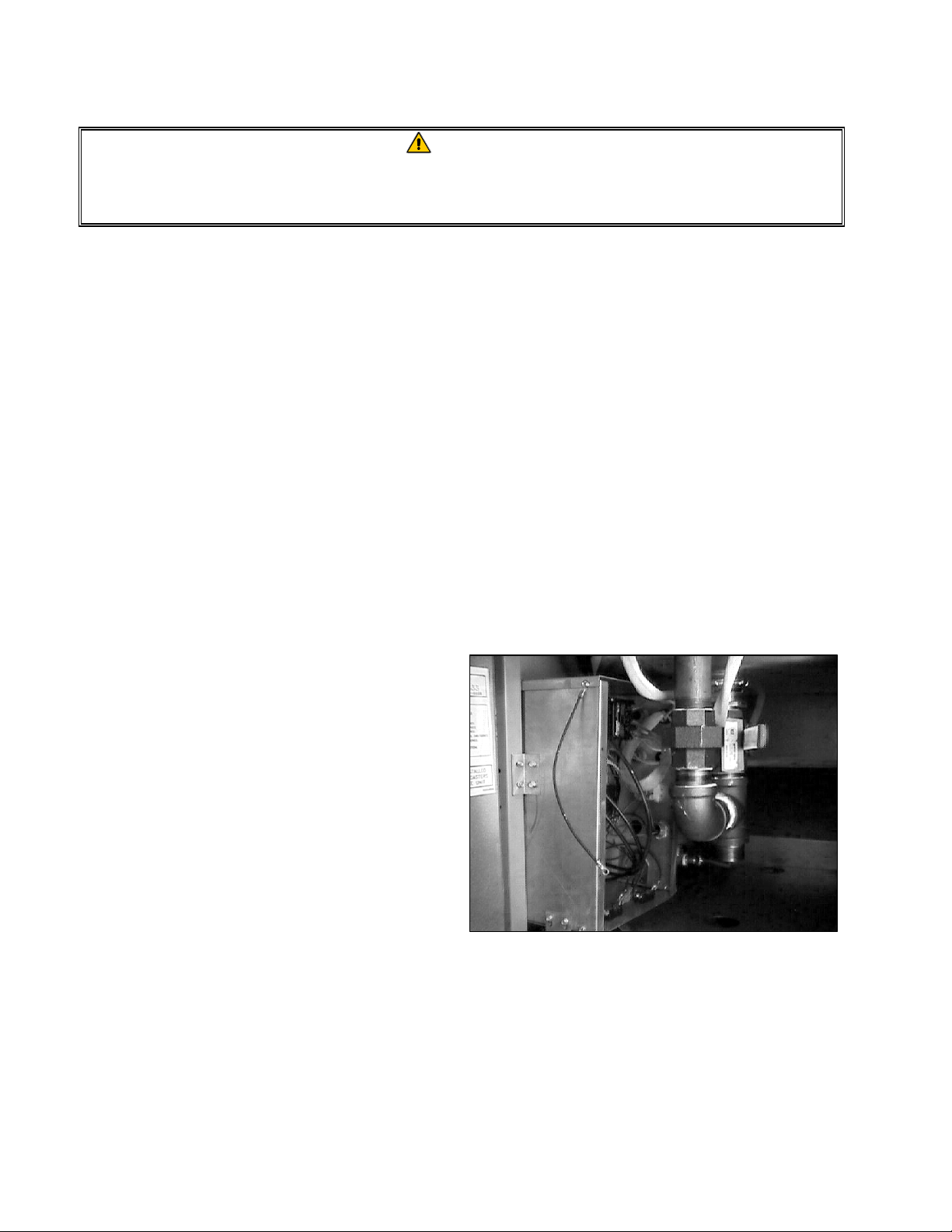
1. Drain the cookpot and disconnect the cooker from the electrical power supply.
2. Remove the cover from the component box.
(It may be helpful to remove the drain
plumbing below the drain valve to better
access the interior of the component box.)
3. On the component to be replaced, make a
note of the wiring connection points.
4. Disconnect the wires and remove the failed
component (see illustration on next page).
Install the replacement component and
reconnect the wiring in accordance with the
notes made in Step 3 or with the wiring
diagram on the door of the unit.
5. Replace the component box cover, being sure to reconnect the ground wire. Replace any drain
plumbing components that were removed and reconnect the cooker to the electrical power
supply.
6-2
Page 29

NOTE: This is a composite drawing for illustrative purposes only. It shows all parts
that may be mounted in the component box. Depending upon the specific
configuration of a particular unit, the actual parts present will vary.
NOTE: Refer to the following wiring diagram s for wiring
connections:
8050377J: 208V through 230V 8SMS, 8BC, 8C
8050462C: 480V/120V 8SMS, 8BC, 8C
Basket Lift Relay (8SMS, 8BC only)
System Fuse and Holder (all units)
Contactor Block (all units)
Basket Lift Wiring Conduit (8SMS and 8BC only)
Element Wiring Conduit (all units)
15-pin Wiring Harness Connecting Plug (all units)
Transformer (all units)
120V Power Cord (480V/120V units only)
Solenoid Valve (units with Autofill/Autoskim only)
Terminal Block (all units)
Basket Lift Fuse and Holder (8SMS, 8BC only)
6.3.3 Replacing the Element
1. Drain the cookpot and disconnect the cooker from the electrical power supply.
2. Remove the cover from the component box. (It may be helpful to remove the drain plumbing
below the drain valve to better access the interior of the component box.)
3. Make a note of where the leads are
connected to the contactor block,
then disconnect the leads.
Secure the high-limit
thermostat along the inside of
this leg with two metal wire ties.
4. Cut the wire ties on the fiberglass
insulation and remove the
insulation from the element leads.
5. Cut the metal wire ties that secure
the high-limit thermostat to the
Standoff
element, being careful not to bend
the thermostat.
6. Remove the brass nuts from the
element legs and carefully pull the
failed element from the cookpot.
Teflon Washer
shown shortened for clarity.
Brass Nut
29-inch (73.7 cm) leads
6-3
Page 30
7. Position the replacement element in the cookpot with the standoffs on the bottom of the cookpot,
and thread the element leads through the Teflon washers recovered from the failed element.
Secure the element in place with the nuts removed in Step 5.
8. Install two metal wire ties to secure the high-limit thermostat against the inside of the left leg of
the element.
9. Thread each set of element leads through the fiberglass insulation removed in Step 4 and secure
the insulation in place with a wire tie as close as possible to the brass nut.
10. Thread one set of leads into the component box and connect them to the contactor block in
accordance with the notes made in Step 3 or the wiring diagram on the door. NOTE: The leads
are numbered to facilitate making proper connections. Repeat this step for the remaining set of
leads.
11. Replace the cover on the component box, being sure to reconnect the ground wire. Reinstall any
drain plumbing components that were removed, and reconnect the unit to the electrical power
supply.
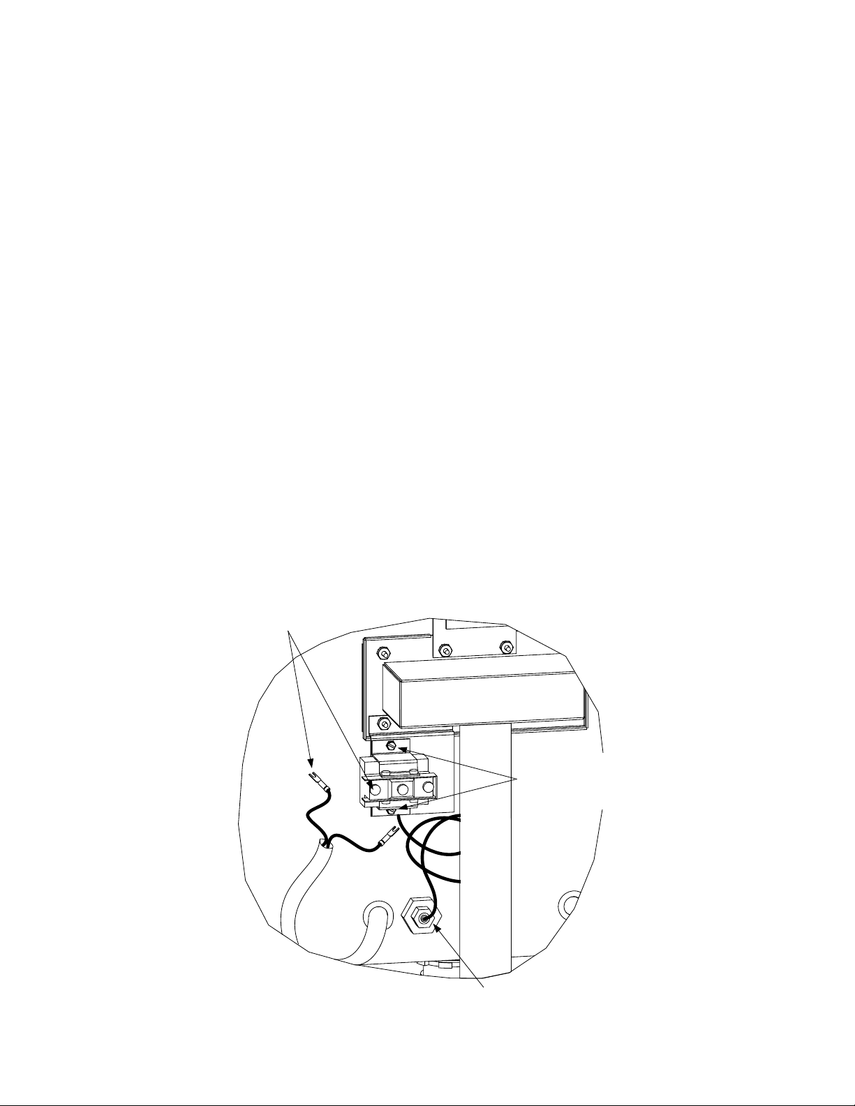
6.3.4 Replacing the High-Limit Thermostat
1. Drain the cookpot and disconnect the cooker from the electrical power supply.
2. Cut the metal wire ties securing the thermostat body to the element.
3. Open the control panel by removing the screws in each upper corner. Mark and then disconnect
the two leads connected to the thermstat terminals.
Mark and disconnect wires from
the thermostat terminals.
Remove the two
screws securing the
thermostat to the
mounting bracket.
Loosen the small compression nut, then
unscrew the large fitting from the cookpot.
6-4
Page 31
4. Loosen the small compression nut, then unscrew the large fitting from the cookpot.
5. Remove the two screws securing the thermostat to the mounting bracket. (NOTE: It is not
necessary to remove the bracket.) Pull the thermostat from the cookpot.
6. Carefully insert the replacement thermostat into the cookpot, being careful not to bend the shaft.
7. Position the thermostat along the inside of the left leg of the element and secure it in place with
two metal wire ties.
8. Unscrew the small compression nut from the large fitting on the replacement thermostat. Apply
thread sealer to the large fitting and screw the fitting securely into the cookpot. When the large
fitting is tight, screw the small compression nut into the large fitting and tighten.
9. Coil the thermostat capillary tube as necessary to achieve a neat installation and attach the
terminal block to the mounting bracket using the screws removed in Step 5.
10. Reattach the leads disconnected in Step 3, being sure to reconnect them in accordance with the
wiring diagram on the door of the unit or the markings made when they were disconnected.
11. Return the control panel to the closed position and secure in place with the screws removed in
Step 3.
12. Reconnect the unit to the electrical power supply.
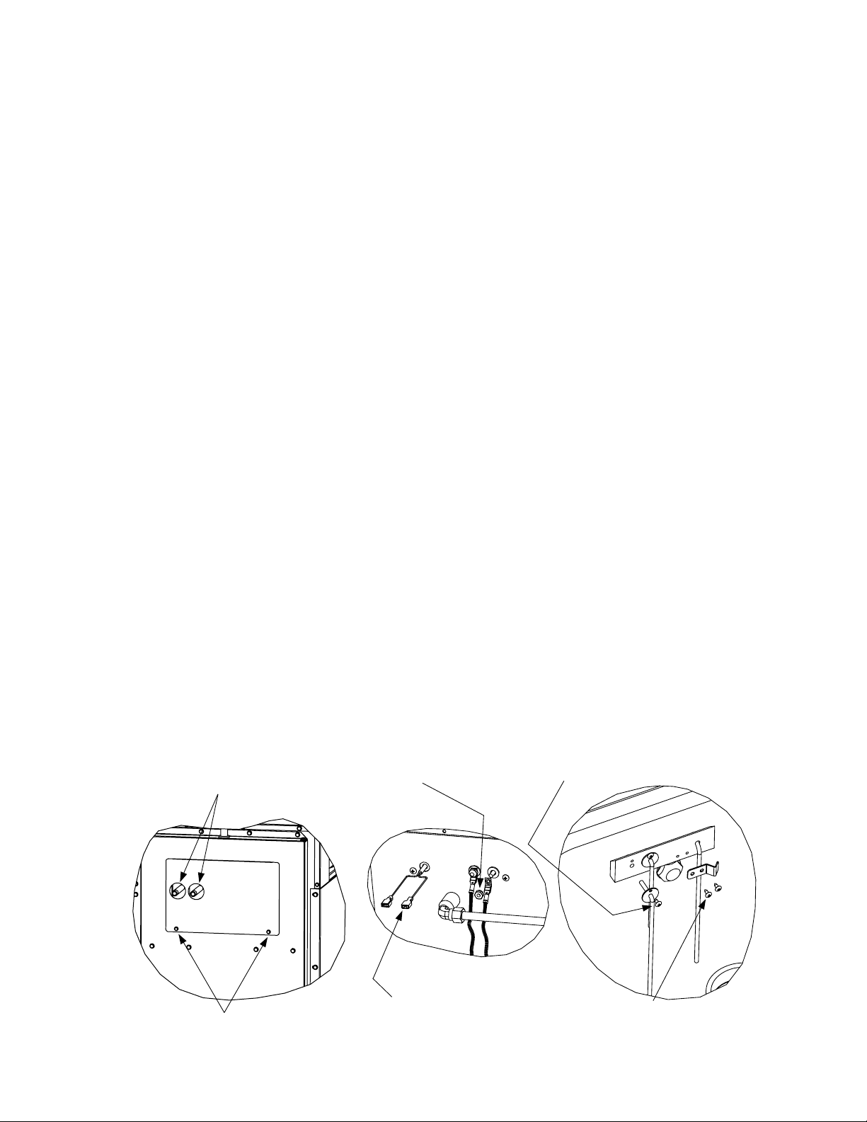
6.3.5 Replacing a Water Level Sensor or the Temperature Probe
1. Drain the cookpot and disconnect the cooker from the electrical power supply.
2. Remove the basket lift arm by lifting it straight up from the lifter rod. Remove the probe cover
by lifting it straight up from the probe block.
3. At the rear of the unit, remove the two screws securing the access panel and remove the panel.
Disconnect incoming
water lines from nipples.
If replacing a water level sensor:
Remove its Keps nut to disconnect
the lead.
Remove the retaining screw from the sensor
flange and pull the sensor from the probe
block.
Remove these two screws
and remove the access panel.
If replacing the temperature probe:
Mark the wiring harness leads and
disconnect the probe leads at the
push on connectors.
6-5
Remove the screws from the probe bracket
and push the probe out the back of the probe
block.
Page 32

4. If replacing a water level sensor:
a. Disconnect the lead by removing the keps nut holding it in place.
b. Remove the screw in the sensor flange.
c. Carefully pull the failed sensor from the probe block and replace with the new sensor.
d. Reattach the lead and reverse Steps 1-3 to complete the procedure.
5. If replacing the probe:
a. Mark the wiring harness leads and disconnect them from the probe leads at the push-on
connectors.
b. Remove the two screws in the probe bracket.
c. Carefully pull the probe from the probe block and replace with the new probe.
d. Reattach the leads and reverse Steps 1-3 to complete the procedure.
6.3.6 Replacing the Pressure Regulator
1. Drain the cookpot and disconnect the cooker from the electrical power supply.
2. Turn off or disconnect the water supply to the cooker. Disconnect the incoming water line where
it connects to the cooker.
3. At the rear of the unit, remove the two screws securing the access panel in place and pull it back
over the water lines sufficiently to allow access to the connections inside.
Disconnect incoming
water lines from nipples.
Loosen this compression fitting.
Remove these two screws and
remove the access panel.
Loosen this compression fitting.
4. At the regulator, loosen the compression fitting on the water line to the solenoid valve. Loosen
the compression fitting at the faucet inlet manifold. Remove the regulator from the unit.
5. Recover the fittings from the failed regulator and install them on the replacement using thread
sealer on all connections.
6. Reverse Steps 1-4 to reinstall the regulator, being sure to apply thread sealer to all connections.
7. Adjust the regulator to not more than 40 PSI (2.8 Kg/cm
2
) (275.79 kPa).
6-6
Page 33
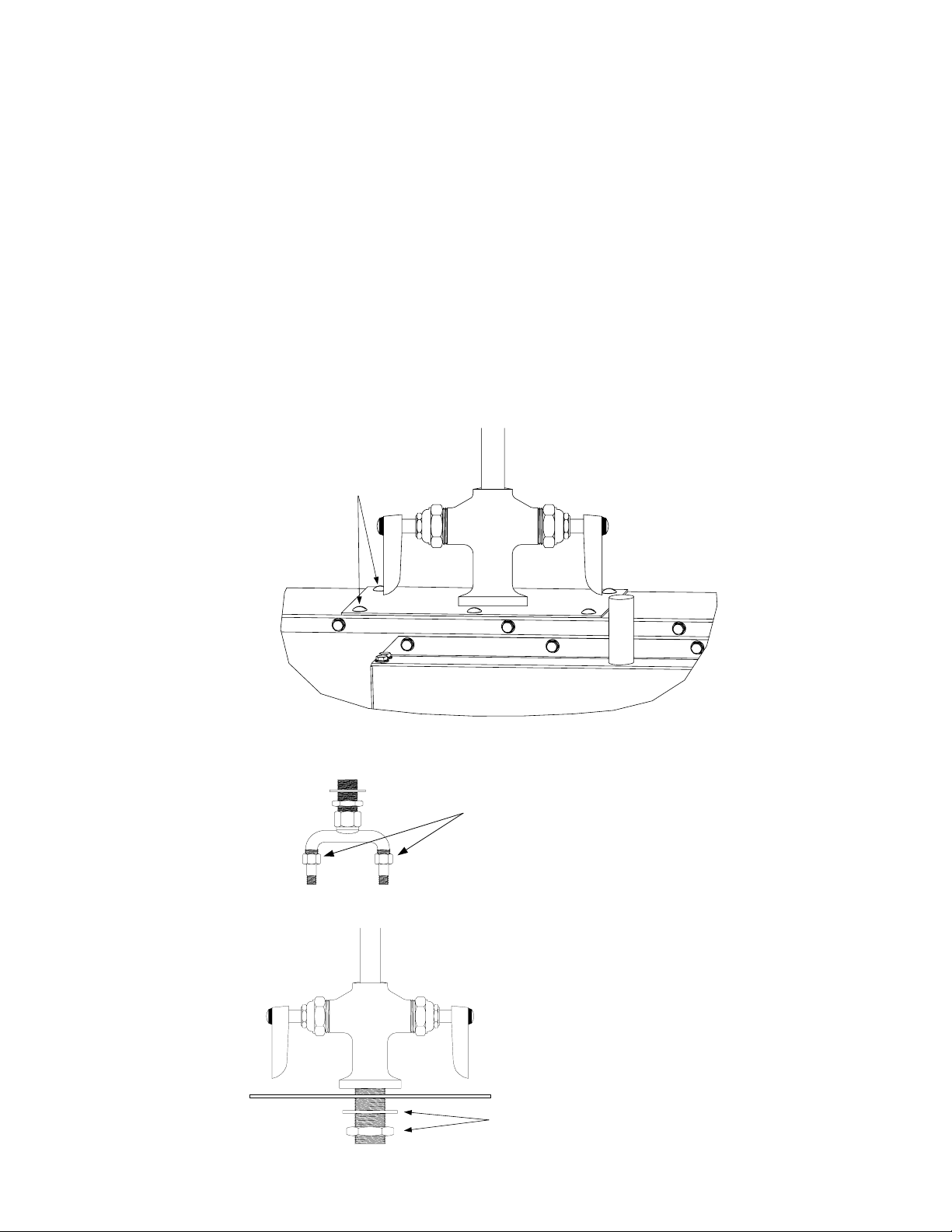
6.3.7 Replacing the Water Faucet
1. Drain the cookpot and disconnect the cooker from the electrical power supply.
2. Turn off the water supply to the cooker.
3. Disconnect the incoming water lines at the nipples that protrude from the holes in the upper
access panel. If necessary, remove any quick-disconnect fittings that would prevent the access
panel from being removed. Remove the two screws securing the access panel in place and
remove the panel (see illustration above).
4. If the cooker is equipped with a pressure regulator, disconnect the regulator by loosening the
compression fitting on the outlet side (see illustration in Section 6.3.6 above).
5. Remove the screws from the faucet mounting plate and lift the entire faucet assembly from the
unit.
Remove the five screws in the
mounting plate and lift the faucet and
plate clear of the unit.
6. Separate the faucet manifold from the remainder of the plumbing as shown in the illustration
below.
Loosen these fittings to separate the
faucet from the water supply system.
7. Disassemble the faucet from the mounting plate by removing the jamb nut and washer.
Remove jamb nut and washer to separat e
the faucet from the mounting plate.
6-7
Page 34

8. Assemble the replacement faucet to the mounting bracket and complete the procedure by
reversing Steps 1-6.
6.3.8 Replacing the Cookpot or Rinse Tank
1. Disconnect the unit from the electrical power supply and from the water supply.
2. Remove the cover from the component box, mark the element leads, disconnect them from the
contactors, and pull them out of the component box.
3. Remove the top cap to expose the pot hold-down bracket assembly. Remove the two Keps nuts
attaching the assembly to the cookpot or rinse tank. Loosen but do not remove the screws in the
top of the bracket. Remove the two screws attaching the bracket to the cabinet frame and
remove the bracket assembly from the unit. On units with a rinse tank, remove the screw
securing the connecting strip.
Remove screw in each
corner and remove top cap.
Remove screw from
connecting strip.
Remove screws.
Loosen screws in
top of bracket.
Remove Keps nuts.
4. At the rear of the unit, disconnect the incoming water lines (and any attached quick-disconnect
fittings) from the nipples protruding from the upper access panel. Remove the panel and
disconnect the water level sensor and temperature probe leads. If the cooker is equipped with the
Autofill feature, disconnect the Autofill water line at the frypot end.
Disconnect incoming
water lines from nipples.
Remove these two screws and
remove the access panel.
Disconnect Autofill water
line at this fitting.
Mark the wiring harness leads and
disconnect the probe leads at the
push on connectors.
Remove Keps nuts to
disconnect the sensor leads.
6-8
Page 35

5. If the unit is equipped with a pressure regulator, disconnect the regulator from the water line at
the outlet side.
Disconnect at this
compression fitting.
6. Remove the screws securing the fluecap assembly to the back panel of the cabinet and remove
the assembly from the unit. On 8SMS units, remove the connecting strip disconnected in Step 4.
Remove the screws securing the flue
cap to the back panel of the cooker.
7. Using an assistant, lift the cookpot or rinse tank up and out of the cabinet.
8. Recover the components from the failed cookpot or rinse tank and install on the replacement
cookpot or rinse tank.
9. Reverse steps 1 through 10 to complete the procedure.
6-9
Page 36

6.3.9 Replacing the Basket Lift Motor and Related Components
1. Disconnect the unit from the electrical power supply and dismount the basket lift arm. Attach a
pair of Vise Grip™ pliers (or a similar locking device) to the basket lift rod where it protrudes
from the cabinet to prevent it from sliping back down into the cabinet when the basket lift link is
disconnected from the bellcrank.
2. Remove the lower basket lift access panel.
3. Mark and disconnect the wires attached to the microswitch. Disconnect the white motor wire at
the inline connector. Cut wire tie, if present, and carefully push all wires back into the cabinet
through the holes in the motor mount.
4. Remove the four slot-head screws that secure the motor mount assembly into the cabinet.
5. Disconnect the basket lift link from the bellcrank and remove the motor mount assembly from
the cabinet.
6. Remove the failed component as shown in the illustration below and install the replacement
component.
7. Complete the procedure by reversing steps 1-5.
6-10
Page 37

6.4 Troubleshooting
6.4.1 How the Autofill System Works
The heart of the automatic filling (AutoFill) system is a normally closed solenoid valve that opens
when 24VAC is applied. When the controller is turned on, it checks to see if the upper water level
sensor is grounded by contact with water in the cookpot. If it is not, circuitry in the controller forms
a ground for the 24VAC supplied to the solenoid, allowing the valve to open. When the water level
in the cookpot reaches the upper water level sensor, the sensor is grounded, causing the controller to
break the solenoid ground, thus shutting off the inflow of water.
Starch or lime build-up on the upper water level sensor may keep the ground from forming, therefore
the sensor must be kept clean and its lead firmly connected. NOTE: Do not use deliming solution to
clean these units. Use of deliming solution will damage all stainless steel parts.
This unit will not operate with distilled water. Pure water is non-conductive, so the required ground
cannot be formed. If highly filtered or purified water is used, adding ⅛-cup of baking soda to the
water will usually provide sufficient mineral content for the ground to form.
NOTE: In units equipped with the AutoSkim feature, when the skim switch on the controller is
pressed, a logic circuit in the controller automatically interrupts the 24VAC ground for three seconds
every minute until the switch is again pressed. Therefore, failure of the AutoSkim feature will be
due to a malfunctioning controller and not the solenoid valve.
6.4.2 How the Water Heating System Works
To prevent energizing the heating elements when there is no water in the cookpot, these units are
equipped with a low-water level sensor that must be grounded by contact with the water in the
cookpot before the control circuitry will apply power to the elements.
Starch or lime build-up on the low-water level sensor may keep the ground from forming, therefore
always make sure the sensor is clean and its lead is firmly connected. NOTE: Do not use deliming
solution to clean these units. Use of deliming solution will damage all stainless steel parts.
The units will not operate with distilled water since pure water is non-conductive. In order for the
ground to form, there must be some mineral content in the water. If highly filtered or purified water
is used, add ⅛-cup of baking soda to the water each time the cookpot is emptied and refilled.
In addition to the low-water level sensor discussed above, the water heating system has five more parts:
the high-limit thermostat, the temperature probe, the contactor block, the element, and the controller.
The high-limit thermostat functions as a normally closed switch. If the water in the cookpot falls
below the low-water level sensor but the sensor remains grounded for whatever reason, the highlimit switch will open when the element temperature reaches 400ºF ±15 (204ºC ± 9), cutting off
power to the contactor coil and thus to the element.
The temperature probe is used only when the unit is in the simmer mode. When the operator
selects the simmer mode, logic circuits in the controller monitor the temperature of the water and
cycle power to the element on and off to maintain the temperature at the setpoint programmed into
the controller.
6-11
Page 38

The contactor block is the terminal block to which the element leads are connected and where
actual contact is made between the leads and the line voltage. Built into the contactor block is a coil
(electronic switch) that closes when a ground for the 24VAC from the transformer is supplied by the
controller calling for heat. When it closes, contact is made between the incoming line voltage and
the element leads.
The element is a resistive heating device. That is, when voltage is applied to the element, the
element gets very hot due to its resistance to current flow through it. The heat generated is
transferred directly to the water in which the element is immersed.
The controller is the interface between the operator and the other components of the equipment. In
the water heating system, its function is to control the application of line voltage to the heating
element via the contactor coil.
Troubleshooting the water heating system consists of checking the above components for proper
operation, as detailed in the troubleshooting diagrams on the next page.
6.4.3 Technician Troubleshooting Guides
TROUBLESHOOTING
THE AUTOFILL
SYSTEM
Solenoid valve
does not open
when water is
below upper water
level sensor.
Is 24VAC
present at pin 6
of the 15-pin
plug?
Yes
Check for shorting
of sensor to ground. If
sensor is not shorted,
computer has failed.
Replace.
Computer has
failed. Replace .
No
No
Problem resolved. Yes
Probable cause is
loose/broken wiring
or damaged sensor.
Valve has failed.
What is the
problem?
Replace.
Yes
Is AutoFill
functioning
properly?
No
Add 1/8 cup
baking soda to
water and stir.
Solenoid valve
does not close
when wat er
reaches upper
water leve l sensor .
Is 24VAC
present at pin 6
of the 15-pin
plug?
No
Clean sensor with
a scouring pad.
Yes
Is AutoFill
functioning
properly?
Substitute a
controller kn own to
be working for
suspect controller.
6-12
Is AutoFill
functioning
properly?
YesNo
Problem resolved.
Page 39
Technician Troubleshooting Guides (Continued)
If the basket lift motor is activating, but the basket lift fails to raise
TROUBLESHOOTING
THE BASKET LIFT
Is 3-Amp
fuse in the
component box
OK?
Yes
With the basket lift
in the UP position, is 13-17VDC
present at pin 10 of 15-pin plug (0
volts if in DOWN position)?
Yes
or lower, or if its movement is erratic, the probable cause is
jamming or binding of the basket lift rod. Apply a light-weight
white grease (such as Lubriplate
TM
) to the rod. If this does not
correct the problem, check for a bent or otherwise damaged rod and
link, and for a loose bellcrank.
Replace fuse.No
No
Probable cause is a
failed controller.
With the basket lift
in the UP position, is 13-17VDC
present at relay terminal A (0 volts
if in DOWN position)?
Yes
With the basket lift
in the UP position, is line voltage
present at the NC (lower) terminal of the
microswitch (middle terminal if in
DOWN position)?
Yes
With the basket lift in the same
position as for the previous check, is line
voltage present at the Common (upper)
terminal of switch?
Yes
No
Probable cause is a
No
Probable cause is a
No
Probable cause is
failed/loose wiring.
failed relay.
failed switch.
Probable cause is a
failed motor.
6-13
Page 40

Technician Troubleshooting Guides (Continued)
TROUBLESHOOTING
THE CONTROLLER
Are the fuses in
the component
box OK?
Yes
Is 24VAC
present at pin 1?
Yes
Is 24VAC present at pin 4 when
off and zero VAC when calling for
Is 24VAC present at pin 6 when
not
heat?
Yes
filling and is pin 6 grounded
when filling?
Replace fuse.No
Is 24VAC
No No Replace transformer.
present on
transformer
secondary?
No
Replace controller.No
Yes
On 8SMS and 8BC units, is 13-17VDC
present at pin 10 when lift is in
and zero VDC when lift is in
position?
Yes
On 8SMS and 8BC units, is
13-17VDC present at pin 12?
UP
DOWN
position
Yes
No
6-14
No
Is 2-3VDC
present at pin 13?
No
Controller is OK.Yes
Page 41

Technician Troubleshooting Guides (Continued)
Before performing the follow ing checks, disconnect the unit from the
electrical power source and check all wiring connections involved to
ensure they are secure.
Each of the following checks is to be performed with the unit connected to the
electrical power supply, with the controller on and calling for heat, and with
enough water in the cookpot to cover the lower water level sensor.
TROUBLESHOOTING
THE HIGH-LIMIT
THERMOSTAT
Is 24VAC
present at the C
terminal of the
high-limit?
Yes
High-limit is OK.
No
High-limit has
failed. Replace.
Water boils in
simmer mode.
Check for shorted probe circuit.
Probe voltage at pin 13 should be:
Approx 1.8VDC @ 60ºF (16ºC)
Approx 2.0VDC @ 100ºF (38ºC)
Approx 2.5 VDC @ 212ºF (100ºC)
Probe resistance should be:
Approx 552 ohms @ 60ºF (16ºC)
Approx 655 ohms @ 100ºF (38ºC)
Approx 1000 ohms @ 212ºF (100ºC)
Are readings
within
specifications?
TROUBLESHOOTING
THE TEMPERATURE
PROBE
What is the
problem?
Probe is OK.
Yes Yes
Calibrate
controller.
Water temperature
is too low in
simmer mode.
Check continuity
of probe.
Continuity OK?
TROUBLESHOOTING
THE CONTACTOR
COIL
Is 24VAC
present at pin 4 of the 15pin plug when controller is
calling for heat?
Yes Yes
Probable cause is
failed controller.
No
Probe is shorted.
Is button in the
center of the contactor
block depressed?
Contactor coil is
OK. Element has
failed. Replace.
No
Replace.
6-15
Contactor coil has
No
No
Probe is open.
Replace.
failed. Replace.
Page 42

6.5 Wiring Diagrams
6-16
Page 43

1 2 3 4 5 6 7 8 9101112131415
SOUND DEVICE
NC
NO VOLTAGE
PROBE
TEMPERATURE
2 TO 3
VOLTS DC
DEPENDING
ON THE
WATER
TEMPERATURE
13 TO 17
VDC
VRELAY
BASKET LIFT
WHEN SOUNDING
0 VOLTS WHEN
BASKET IS DOWN
13 TO 17 VDC
WHEN BASKET
IS UP
GROUND WHEN
FILLING 24VAC
WHEN NOT
FILLING
COMPUTER CONTROL
NO VOLTAGE
WHEN HEATING
24VAC WHEN
OFF
24VAC GND.
8050462C
ALL READINGS REF ERENCED TO GROUND WITH THE COMPUTER OPERATI NG
1 2 3 4 5 6 7 8 9101112131415
SD
3 TO 5
VOLTS
NC
DO NOT MEASURE
WATER LEVEL PROBES
FILL
WATER
NC
NC HEAT
COM
POWER IN
HOT
CONNECTOR
71C
BASKET LIFT SHOWN
IN UP POSITION
GM
GEAR
MOTOR
C
N.C. N.O.
MICRO
SWITCH
43C
XX
44C
NC
2
TEMP.
PROBE
BASKET LIFT RELAY
NO
5
A B
24VDC
7
COM
13C 14C
11C
HIGH
WATER
SENSOR
OPTIONAL
AUTOFILL
5C
HIGH LIMIT
C
N.C.
LOW
WATER
SENSOR
24 VAC
SOLENOID
24C
1C
24 VAC
COIL
CONTACTOR
1C 2C 4C 7C 9C 10C 12C
COM
120 VAC
LINE
LOAD
24VAC 50 VA.
3C
TRANSFORMER
11C
71C
71C
16C
71C
8C
11C
FUSE
5 AMP
GRN
TYPE 3AG
WHITE
BLACK
120 VAC
CORDSET
15C
SPLICE
IN-LINE
3 PHASE 3 WIRE
FIELD CONNECTION
IN-LINE SPLICE
480/120VAC DUAL VOLTAGE CONFIGURATION
L1 L2 L3
13 5 7 911
2 4 6 8 10 12
253 46
1C1 1C2 1C3
1HV 2HV 3HV
1
6-17
Page 44

ELECTRIC COOKERS 8SMS, 8BC AND 8C
7.1 Accessories
1
3
5
CHAPTER 7: PARTS LIST
2
4
7
13
8
11
9
12
6
ITEM PART # COMPONENT
1 810-2112 Basket Hanger, Wire Form
2 809-0171 Basket Hanger Screw
3 803-0155 Holder, Portion Cup
4 803-0018 Cup, Portion
5 823-1662 Basket, Bulk Product
6 803-0167 Rack, Basket Support
7 910-2545 Strainer
8 806-3811 Legs, Package of 4 Adjustable
9 810-0357 Caster w/Brake
10 810-0356 Caster w/o Brake
* 826-1113 Kit, Leg/Caster Mounting (1 kit required per leg or caster)
11 826-1095 Kit, Anchor Strap (for use w/Cookers equipped with legs)
12 826-0900 Kit, Chain Restraint (for use w/Cookers equipped with casters)
13 803-0234 Brush, Probe Cleaning
* 823-2608 Connecting Strip, 8SMS
* Not illustrated
10
7-1
Page 45

7.2 Basket Lift Components
12
13
14
15
1617181920212223
25
26
27
1 2 3 4 5 6 7 8 9 10 11
24
7-2
Page 46

ITEM PART # COMPONENT
1 809-0127 Screw, ¼-20 x ½-inch Round Head
2 810-0192 Rod, Basket Lift
3 823-1840 Arm, Basket Lift
4 900-7226 Enclosure, Basket Lift
5 809-0050 Nut, 8-32 Hex Head
6 Motor, Basket Lift
807-0107 120 VAC
807-0108 240VAC
7 920-3095 Mount, Basket Lift Motor
8 809-0049 Nut, 6-32 Hex Head
9 812-0138 Insulation, Paper
10 807-0240 Microswitch, BA-2RV22-D6
11 807-0124 Bushing, Plastic
12 809-0194 Washer, 5/16-inch SAE Flat
13 810-0220 Spacer, Tubular
14 809-0203 Washer, ½-inch Nylatron
15 809-0155 Screw, Leveling
16 809-0063 Nut, ⅜-inch Jam
17 809-0196 Washer, ⅜-inch SAE Flat
18 810-0052 Bellcrank
* 809-0480 Setscrew, ¼-28 x ⅝-inch (secures Bellcrank to motor shaft)
19 809-0097 Screw, 6-32 x 1-inch Slotted Truss Head
20 809-0113 Screw, 8-32 x 1½-inch Slotted Truss Head
21 810-0172 Button, Plug
22 809-0076 Nut, ¼-20 Expansion
23 809-0134 Screw, ¼-20 x 1½-inch Round Head
24 920-3190 Link, Basket Lift
25 810-0170 Pin, ¼-inch x ⅝-inch Spring Dowel
26 813-0035 Bushing, Bronze
* 809-0082 Ring, Retaining (secures bronze bushing 813-0035 in place)
27 900-4266 Angle, Bushing Support
* Not illustrated
7-3
Page 47

7.3 Cabinetry
19
11
17
22
24
20
21 23
12
14
13
15
11
12
26
18
16e
17
16
25
16d
16c
16b
2b
7
6
5
4
3
1
2a
8
9
10
16a
7-4
Page 48

ITEM PART # COMPONENT
1 806-9744SP Door Assembly (does not include handles)
2a 810-1402 Handle, Wireform Door (cannot replace 210-9214)
2b 210-9214 Handle, Eurolook Door (cannot replace 810-1402)
* 809-0266 Screw, Door Handle
* 810-1508 Hinge Bracket, Door
* 806-4487SP Pin Assembly, Door
* 826-1343 Spring, Door Pin
3 806-4735SP Frame Assembly, 8SMS Control Panel
* 910-4308 Blank Control Panel (used on rinse tank side of 8SMS)
4 910-7205 Top Cap, 8SMS
5 823-2609 Flue Cap, 8SMS
6 910-0207 Plate, Faucet Mounting (all models)
7 900-7202SP Divider, 8SMS Cabinet
8 810-1105 Magnet, Door
9 900-7198 Post, 8SMS Door
10 900-4334 Shield, 8SMS Basket Lift Motor
11 Side, Right (all models)
902-7167SP Painted Steel
912-7167SP Stainless Steel
12 Side, Left (all models)
901-7167SP Painted Steel
911-7167SP Stainless Steel
13 900-7201SP Panel, 8SMS Cabinet Back
14 900-4766 Panel, Basket Lift Upper Access (all models)
15 900-4351 Panel, Basket Lift Lower Access (all models)
* 900-7199SP Brace, 8SMS Cabinet Top
* 900-1536 Bracket, Top Half Pot Hold Down (all models)
* 900-1537 Bracket, Top Half Pot Hold Down (all models)
16 806-5067SP Guide Assembly, Basket Lift (all models)
16a 809-0047 Nut, Cap
16b 810-0194 Roller
16c 810-0374 Spacer
16d 809-0508 Bolt, ¼-20 x 1¼-inch
16e 823-1803 Bracket
17 900-7156SP Channel, Base Side (all models)
18 900-7200SP Channel, 8SMS Base Front and Rear
* 806-5209SP Pad Assembly, Leg or Caster Mounting (all models)
19 823-1714 Flue Cap, 8BC/8C
20 910-1514 Top Cap, 8BC/8C
21 806-4725SP Frame, 8BC/8C Control Panel
22 900-7155SP Panel, 8BC/8C Cabinet Back
23 900-7277 Stiffener, Cabinet Side (all models)
24 900-4279SP Brace, 8BC/8C Cabinet Top
25 900-4280SP Channel, 8BC/8C Base Front and Rear
26 900-7848 Shield, 8BC/8C Vapor
* Not illustrated
7-5
Page 49

7.4 Cookpot and Rinse Tank Components
30
29 8 8 9 10
12
3125 33 32
11
14
19
24
23
22
21
20
9
10
15
7 5 4 3
28
11
12
13
14
15
16
34
17
27
1 2 3 4 5 6 7 8 9 10
26
25
24
23
22
21
20
19
18
7-6
Page 50

ITEM PART # COMPONENT
1 810-0698 Cookpot, 8SMS/8BC/8C
2 810-1697 Block, Probe
* 826-1081 Kit, Probe Block (old style with pins and cover)
* 823-2791 Cover, Probe Block
* 823-1942 Cover, Probe (old style with holes for pins)
3 823-1920 Sensor, Lower Water Level (approximately 7 inches long)
4 823-1921 Sensor, Upper Water Level (approximately 4¼ inches long)
* 809-0193 Washer, ¼-inch Nylon (used on water level sensors)
* 807-0037 Tab, Push-on Male (used on water level sensors)
5 810-0713 Nozzle, Spray
6 910-1804 Bracket, Temperature Probe Retaining
* 809-0357 Screw, #6 x ⅜-inch (used to secure sensors and probe bracket in place)
7 806-4764 Temperature Probe (with connectors)
8 816-0113 Gasket, Overflow Drain
9 900-1537 Bracket, Pot Hold Down Bottom
10 809-0256 Nut, 10-32 Keps Hex
11 823-1711 Drain, Overflow
12 900-5675 Bracket, High-Limit Thermostat Mounting
13 826-1601 Thermostat, High-Limit (includes high-limit, gasket, and tie wrap)
* 809-0567 Tie Wrap, Metal (secures Hi-Limit Thermostat to Element)
14 810-1826 Handle, Drain Valve
15 814-0047 Sleeve, Red Valve Handle (with logo)
16 813-0395 Union, 1¼-inch NPT
17 813-0070 Elbow, 1¼-inch x 90º NPT
18 813-0394 Tee, 1¼-inch NPT
19 813-0391 Nipple, 1¼-inch NPT Close
20 810-1825 Valve, 1¼-inch NPT Drain
21 813-0397 Reducer, 1½-inch Sink to 1¼-inch NPT
22 816-0221 Washer, 1¾-inch Sink
23 809-0464 Nut, 1½-inch Conduit
24 809-0465 Washer, Sink Drain
25 813-0396 Drain, 1½-inch Sink (includes item 23)
26 809-0204 Washer, ⅝-inch Flat
27 809-0444 Nut, Hex Jam
28 813-0302 Elbow, ¼-inch NPT to ⅜-inch Tube 90º Compression
29 823-1657 Fascia, Overflow Drain
30 809-0360 Screw, #8 x ⅜-inch Hex Washer Head
31 810-0699 Tank, Rinse
32 809-0270 Screw, 10-32 x ½-inch Truss Head
33 809-0192 Washer, ¼-inch Lock with external teeth
34 Element, 8kW, 1- or 3-Ø (includes mounting washer and nut and standoff)
826-1795 208VAC
826-1797 230VAC
826-1798 240VAC
807-1729 480VAC (requires two teflon washers, 809-0204)
* Not illustrated
7-7
Page 51

7.5 Electrical Components and Controllers
12
4
1
2
5
3
2
13 14 15
11
10
8
7
6
3
12
16 17
9
19
20
21
ITEM PART # COMPONENT
1 807-1396 Relay, 24VDC
2 807-1308 Holder, Fuse
3 807-1555 Fuse, 5 Amp
4 809-0362 Screw, #8 x 1¼-inch Hex Head
5 807-0878 Block, Terminal
6 807-0263 Terminal, Split
7 807-0680 Transformer, 208/240VAC – 24VAC
8 807-0070 Terminal, Ground Lug
9 806-4770 Valve Assembly, Solenoid
10 807-0875 Connector, 15-pin Female
11 810-1202 Contactor, 40 Amp 3 Pole
12 809-0361 Screw, #8 x ½-inch Hex Head
13 807-1292 Fitting, Plastic Conduit
14 812-0994 Conduit, ½-inch Plastic (17 inches long)
15 812-0992 Conduit, ½-inch Plastic (15 inches long)
16 900-7853 Cover, Component Box
17 823-1820 Box, Component
18 810-0044 Button, ⅞-inch Plug
19 809-0454 Nut, ½-inch Conduit
20 809-0096 Screw, 6-32 x ⅝-inch
21 809-0250 Nut, 6-32 Keps
* 806-5332 Cordset, Basket Lift (used with 480/120VAC dual-voltage units only)
* WIR0013SP Wire Assembly, 8SMS Contactor Box
* 806-4702 Cable, 8SMS Controller
* Controller, 8SMS
106-0371 CE and non-CE with AutoFill and AutoSkim
106-0373 CE and Non-CE with AutoFill but without AutoSkim
106-0374 CE and Non-CE without Autofill or Autoskim
* Not illustrated.
18
7-8
Page 52
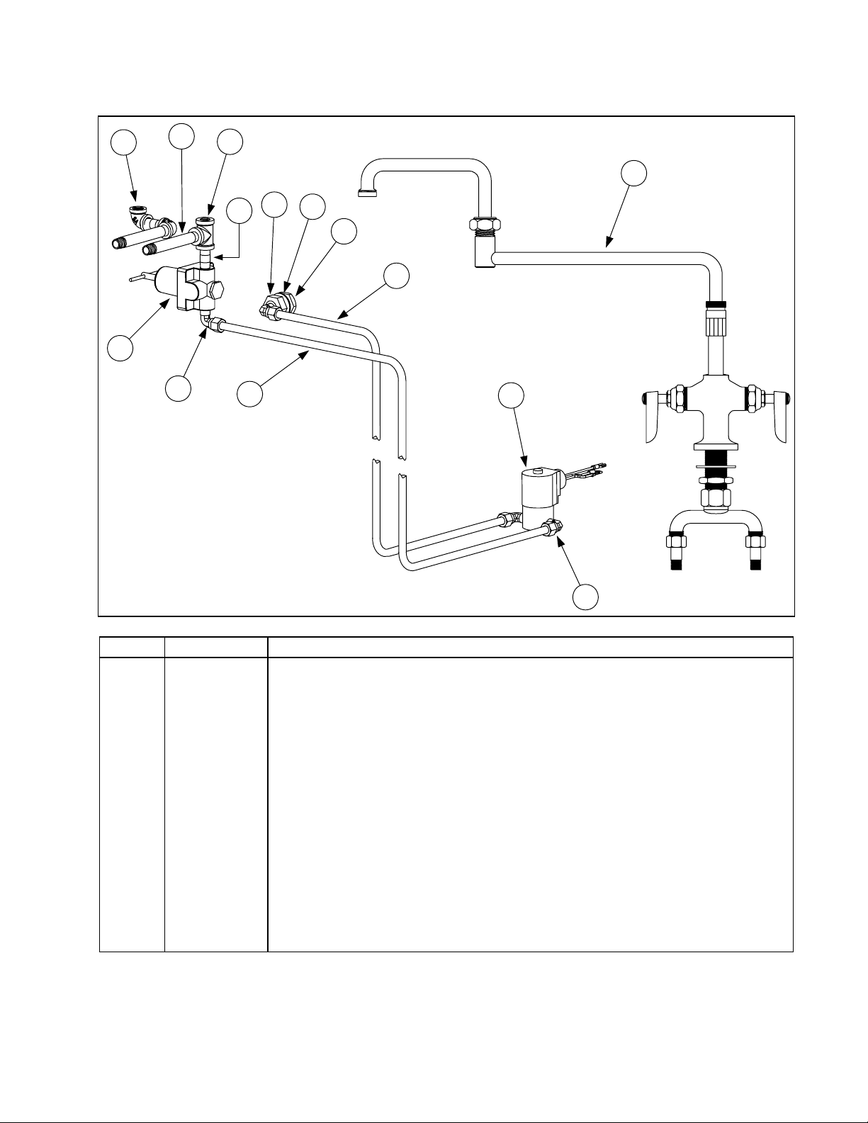
7.6 Water Supply Components
7
2
8
6
9
3
11
10
4
12
13
5
1
6
ITEM PART # COMPONENT
1 806-4770 Solenoid Assembly, Autofill
2 810-1208 Regulator, Water Pressure
3 813-0412 Faucet, Double Jointed
* 826-1132 Kit, Faucet Repair (contains two valve assemblies)
4 900-2114 Tube, Copper Water Supply
5 910-2496 Tube, Stainless Steel Autofill
6 813-0302 Elbow, Brass ⅜-inch Tube to ¼-inch NPT (w/Compression Nut)
7 813-0448 Elbow, Brass ¼-inch x 90º NPT
8 813-0473 Nipple, Brass ¼-inch x 4-inch NPT
9 813-0449 Tee, Brass, ¼-inch NPT
10 813-0471 Nipple, Brass ¼-inch x 1.5-inch NPT
11 809-0444 Nut, ¾-10 Hex Head Jam
12 816-0114 Gasket, Spray Nozzle
13 810-0713 Nozzle, Spray
* 826-1135 Kit, Non-Autofill to Autofill Conversion
* Not illustrated
7-9
Page 53

ELECTRIC COOKERS 8SMS, 8BC AND 8C
APPENDIX A: SERIES CODE HISTORY
SERIES
CODE
AA 11/05/91 Prototype or field-test unit.
AB 6/22/92 Initial production.
AC 11/18/92
AD 10/25/95
AE 5/16/97
AF 11/23/98
AG 2/22/99
DATE
EFFECTIVE
Minor design changes to improve manufacturability and serviceability.
All critical components interchangeable with series AB.
Labels, wiring diagrams, and rating plate translated in conjunction with
CE approval. No changes to other components.
Added high-limit thermostat to prevent catastrophic failure of element if
there is no water in cookpot.
Redesign of probe block and cover to eleminate mounting pins. New
probe block and cover are not interchangeable with old design, but new
block mounts to cookpot using same holes as old block.
Minor design changes to improve manufacturability and serviceability.
All components interchangeable with series AF.
DESCRIPTION
A-1
Page 54

Shipping Address: 8700 Line Avenue, Shreveport, Louisiana 71106
TEL 1-318-865-1711 FAX (Parts) 1-318-219-7140 (Tech Support) 1-318-219-7135
PRINTED IN THE UNITED STATES
SERVICE HOTLINE
1-800-551-8633
819-5246
04/2015
 Loading...