

Page 1
FilterQuick™ FQG30
Gas Fryer
Parts Manual
This manual is updated as new information and models are released. Visit our website for the latest manual.
*8197116*
Part Number: FRY_P_8197116 08/2015
Page 2
NOTICE
IF, DURING THE WARRANTY PERIOD, THE CUSTOMER USES A PART FOR THIS MANITOWOC FOOD SERVICE
EQUIPMENT OTHER THAN AN UNMODIFIED NEW OR RECYCLED PART PURCHASED DIRECTLY FROM FRYMASTER
OR ANY OF ITS AUTHORIZED SERVICERS, AND/OR THE PART BEING USED IS MODIFIED FROM ITS ORIGINAL
CONFIGURATION, THIS WARRANTY WILL BE VOID. FURTHER, FRYMASTER AND ITS AFFILIATES WILL NOT BE
LIABLE FOR ANY CLAIMS, DAMAGES OR EXPENSES INCURRED BY THE CUSTOMER WHICH ARISE DIRECTLY OR
INDIRECTLY, IN WHOLE OR IN PART, DUE TO THE INSTALLATION OF ANY MODIFIED PART AND/OR PART RECEIVED
FROM AN UNAUTHORIZED SERVICER.
NOTICE
This appliance is intended for professional use only and is to be operated by qualified personnel only. A
Frymaster Factory Authorized Servicer (FAS) or other qualified professional should perform installation,
maintenance, and repairs. Installation, maintenance, or repairs by unqualified personnel may void the
manufacturer’s warranty. See Chapter 1 of this manual for definitions of qualified personnel.
NOTICE
Drawings and photos used in this manual are intended to illustrate operational, cleaning and technical
procedures and may not conform to onsite management operational procedures.
NOTICE TO OWNERS OF UNITS EQUIPPED WITH CONTROLLERS
U.S.
This device complies with Part 15 of the FCC rules. Operation is subject to the following two conditions: 1) This
device may not cause harmful interference, and 2) This device must accept any interference received, including
interference that may cause undesired operation. While this device is a verified Class A device, it has been shown
to meet the Class B limits.
CANADA
This digital apparatus does not exceed the Class A or B limits for radio noise emissions as set out by the ICES-003
standard of the Canadian Department of Communications.
DANGER
Improper installation, adjustment, maintenance or service, and unauthorized alterations or modifications can
cause property damage, injury, or death. Read the installation, operating, and service instructions thoroughly
before installing or servicing this equipment. Only qualified service personnel may convert this appliance to use a
gas other than that for which it was originally configured.
WARNING
After installation of a gas fryer and after any maintenance to the gas system of a gas fryer-manifold, valve,
burners, etc. – check for gas leaks at all connections. Apply a thick soapy solution to all connections and ensure
there are no bubbles. There should be no smell of gas.
DANGER
Adequate means must be provided to limit the movement of this appliance without depending upon the gas line
connection. Single fryers equipped with legs must be stabilized by installing anchor straps. All fryers equipped
with casters must be stabilized by installing restraining chains. If a flexible gas line is used, an additional
restraining cable must be connected at all times when the fryer is in use.
DANGER
The front ledge of the fryer is not a step! Do not stand on the fryer. Serious injury can result from slips or contact
with the hot oil.
DANGER
Do not store or use gasoline or other flammable liquids or vapors in the vicinity of this or any other appliance.
Page 3
DANGER
Do not spray aerosols in the vicinity of this appliance while it is in operation.
DANGER
This product contains chemicals known to the state of California to cause cancer and/or birth defects or other
reproductive harm.
Operation, installation, and servicing of this product could expose you to airborne particles of glasswool or
ceramic fibers, crystalline silica, and/or carbon monoxide. Inhalation of airborne particles of glasswool or ceramic
fibers is known to the State of California to cause cancer. Inhalation of carbon monoxide is known to the State of
California to cause birth defects or other reproductive harm.
DANGER
Improper installation, adjustment, maintenance or service, and unauthorized alterations or modifications can
cause property damage, injury, or death. Read the installation, operating, and service instructions thoroughly
before installing or servicing this equipment.
DANGER
Keep all items out of drains. Closing actuators may cause damage or injury.
DANGER
Prior to movement, testing, maintenance and any repair on your Frymaster fryer; disconnect ALL electrical power
cords from the electrical power supply.
WARNING
Use caution and wear appropriate safety equipment to avoid contact with hot oil or surfaces that may cause
severe burns or injury.
ii
Page 4

FILTERQUICK™ FQG30 SERIES GAS FRYERS
PARTS MANUAL
TABLE OF CONTENTS
CHAPTER 1: Parts List
1.1 Accessories .................................................................................................................................................................................. 1-1
1.2 Doors, Sides, Flue Caps, Top Caps and Casters ............................................................................................................... 1-2
1.3 Drain Valves and Associated Parts ...................................................................................................................................... 1-2
1.3.1 Rotary Actuator Drain Valve ............................................................................................................................. 1-2
1.4 Drain Tube Sections and Associated Parts ....................................................................................................................... 1-3
1.5 Electronics and Electrical Components ............................................................................................................................. 1-4
1.5.1 High-Limit Thermostat and Temperature Probe ...................................................................................... 1-4
1.5.2 Component Boxes ............................................................................................................................................... 1-4
1.5.3 Transformer Boxes .............................................................................................................................................. 1-6
1.5.4 Controllers and Associated Components ................................................................................................... 1-7
1.5.5 Control Panel Frames and Push Pull Rod Assembly ................................................................................ 1-8
1.5.6 Control Panel Frames and Push Button Assembly ................................................................................... 1-9
1.6 Wiring ......................................................................................................................................................................................... 1-10
1.6.1 Controller, MIB, AIF and ATO Wiring Harnesses ..................................................................................... 1-10
1.6.2 Main Wiring Harnesses ................................................................................................................................... 1-11
1.7 Frypots and Associated Components ............................................................................................................................. 1-12
1.7.1 Full-Vat Frypot Components ........................................................................................................................ 1-12
1.7.2 Dual-Vat Frypot Components ...................................................................................................................... 1-14
1.7.3 Frypot Assemblies and Associated Parts .................................................................................................. 1-16
1.8 Oil Return Manifolds ............................................................................................................................................................. 1-17
1.9 Return Valve ............................................................................................................................................................................. 1-17
1.10 Gas Supply and Combustion System Components ................................................................................................... 1-18
1.11 Gas Valves and Associated Components ....................................................................................................................... 1-20
1.12 Filtration System Components ......................................................................................................................................... 1-22
1.13 Filtration Electronic Components .................................................................................................................................... 1-23
1.13.1 MIB (Manual Interface Board) Assembly ................................................................................................... 1-23
1.13.2 AIF (Automatic Intermittent Filtration) Linear Actuator Board Assembly ..................................... 1-24
1.14 ATO (Automatic Top-Off) Components .......................................................................................................................... 1-24
1.14.1 JIB Cradle, JIB Box, JIB Cap and Pick-Up Assembly and ATO Board Assemblies .......................... 1-24
1.14.2 ATO Pump Assembly Non-Bulk ................................................................................................................... 1-25
1.14.3 ATO Pump Assembly Bulk ............................................................................................................................. 1-26
1.14.4 Shortening Melting Unit ................................................................................................................................ 1-27
1.15 Bulk Oil System Components ............................................................................................................................................ 1-28
1.15.1 Bulk Dispose Waste Valve and Test Box .................................................................................
1.15.2 Bulk Manifold and Accessories .................................................................................................................... 1-29
1.16 Basket Lift Assembly and Associated Parts ................................................................................................................... 1-31
1.17 Oil Quality Sensor (OQS) and Associated Parts ............................................................................................................ 1-33
................... 1-28
iii
Page 5
FILTERQUICK™ FQG30 SERIES GAS FRYERS
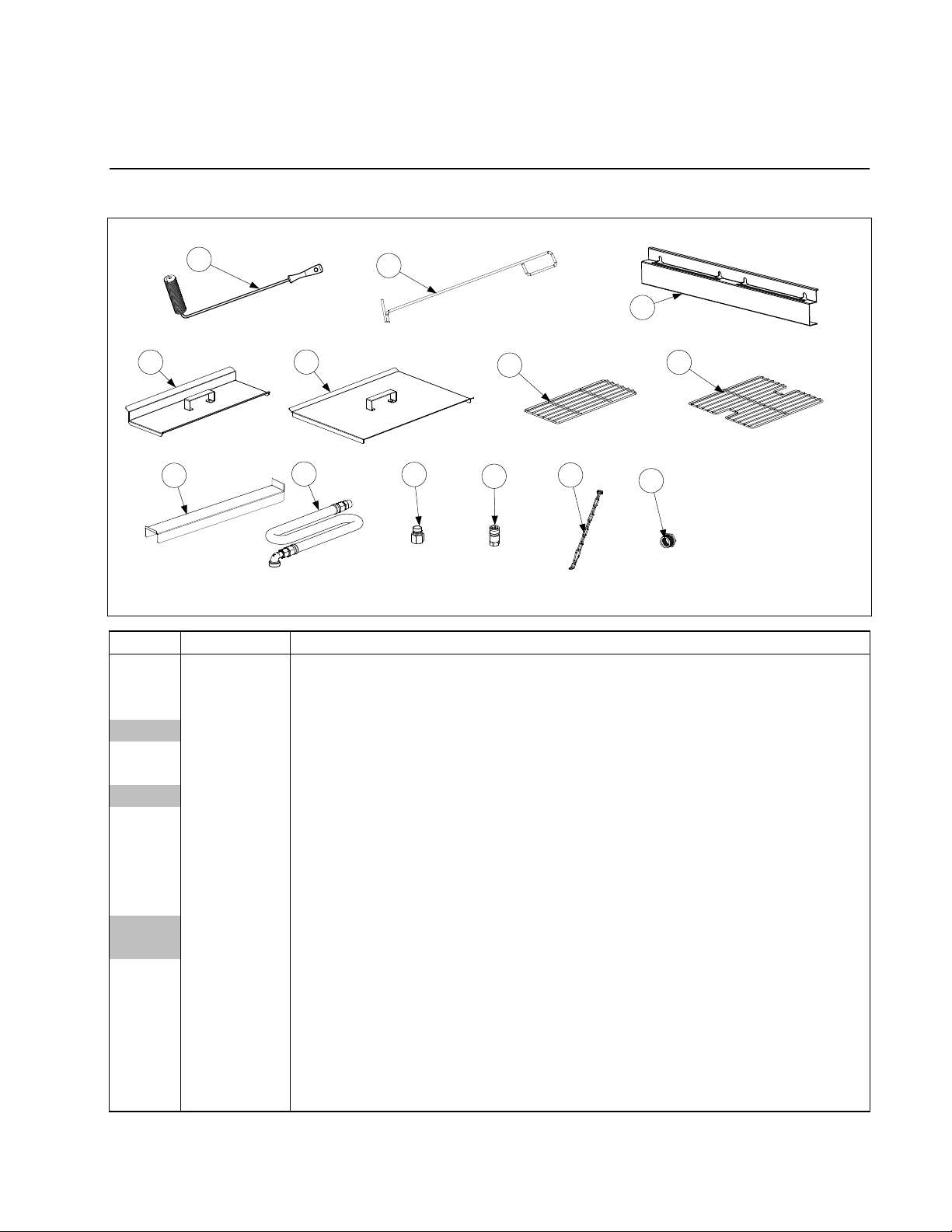
1.1 Accessories
1
4
8
PARTS LIST
2
3
5
9
10
6
11
12
7
13
ITEM PART # COMPONENT
1 8030429 Brush, Frypot
2 8030388 Fryers Friend
3 2307495
Hanger, Basket Two Station (use two for a Four Station fryer)
2307497 Hanger, Basket Three Station
4 1068931 Cover, Frypot, Dual Vat
5 1068930 Cover, Frypot, Full Vat
8260993SP Handle Kit, Frypot Cover (includes handle and screws)
6 8030372 Basket Support Rack, Dual Vat
* 8030375 Basket Support Rack, Full Vat
7 8030136 Basket Support Screen, Full Vat (screen w/handle used in place of Item 8)
8 2302975 Connecting Strip, Frypot
9 8100478 Gas Line, 1-Inch Dormont Flexible
8061698SP 36-Inch (for gas line only (w/o Items 10 and 11), use 8100088)
8061699 48-Inch (for gas line only (w/o Items 10 and 11), use 8100085)
10 8100074 Quick-Disconnect Fitting, 1-Inch Male
11 8100073 Quick-Disconnect Fitting, 1-Inch Female
12 8103745 Quick Disconnect Fittings, ¾” set (includes male and female connectors)
13 8260900 Kit, Chain Restraint
14 8261045 Bushing, Flexible Gas Line (8130032)
* 8030002 Powder, Filter (80- 1-Cup Applications)
* 8030445 Pack, 100-Sheet Filter Paper 16.5 X 25.5
* Not illustrated.
1-1
Page 6
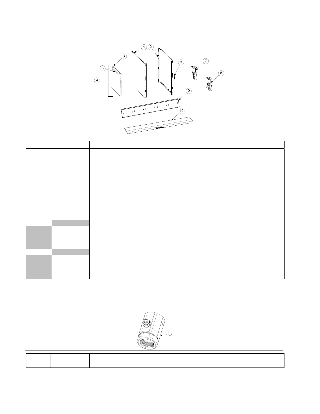
1.2 Doors, Sides, Flue Caps, Top Caps and Casters
ITEM PART # COMPONENT
1 2317908 Side, Standard Cabinet Left SS
2 2327908 Side, Standard Cabinet Right SS
3 8101105 Magnet, Door (vertical) (use 8102346 for horizontal over filter pan)
4 1064397
Door, Left or Right (Left shown – move handle to bottom for right) (use 1080915 for Door w/
Manual Holder)
5 2304960 Handle, Eurolook Door
6 1064067 Pin Assembly, Door
* 8100275 Spring, Door Pin
* 8090970 Retaining Ring
* 2307192 Hinge, Door Lower
7 8100327 Caster without Brake
8 8100944 Caster with Brake
9 Flue Cap-Stainless Steel
8237724 Two Station Fryer
8237727 Three Station Fryer
8237728 Four Station Fryer
8237752 Five Station Fryer
10 Top Cap (Cap for 5-station fryer shown)
8241913 Two Station Fryer
8236635 Three Station Fryer
8236636 Four Station Fryer
1083030 Five Station Fryer
* Not illustrated.
1.3 Drain Valves and Associated Parts
1.3.1 Rotary Actuator Drain Valve
ITEM PART # COMPONENT
1 8103755 Valve, 1¼” NPT Rotary Actuator
1-2
Page 7
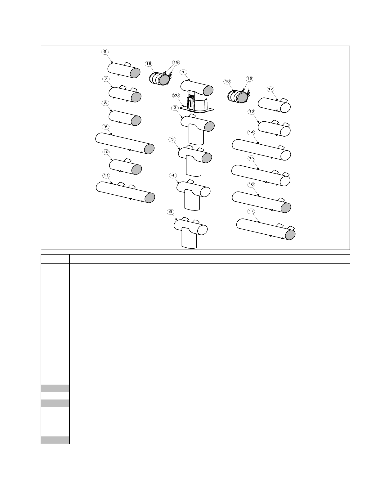
1.4 Drain Tube Sections and Associated Parts
See Section 1.3 for Drain Valve
ITEM PART # COMPONENT
1 1085906
2 1085904
3 1085917
4 1085905
5 1085919
Drain Tube, Dump Left Closed/Right End Open (Use 1085915 for Bulk)
Drain Tube, Dump Full-Vat Left Closed/Right End Open (Use 1085911 for Bulk)
Drain Tube, Dump Dual-Vat Left Closed/Right End Open (Use 1085916 for Bulk)
Drain Tube, Dump Full-Vat Left Closed/Right End Closed (Use 1085914 for Bulk)
Drain Tube, Dump Dual-Vat Left Closed/Right End Closed (Use 1085918 for Bulk)
6 8237322 Drain Tube, Full-Vat Left and Right Open
7 8237324 Drain Tube, Dual-Vat Left and Right Open
8 8103550 Drain Tube, Short, Open Both Ends
9 8103551 Drain Tube, Long, Open Both Ends
10 8238812 Drain Tube, Full -Vat Left and Right Open
11 8238813 Drain Tube, Dual-Vat Left and Right Open
12 8237330 Drain Tube, Full-Vat Left Open/Right End Closed
13 8237331 Drain Tube, Dual-Vat Left Open/Right End Closed
14 8237329 Drain Tube, Full-Vat Left Open/Right End Closed
15 8237326 Drain Tube, Dual-Vat Left Open/Right End Closed
16 8237328 Drain Tube, Full-Vat Left and Right Open 15.31”
8238791 Drain Tube, Full-Vat Left and Right Open 18.95”
17 8237327 Drain Tube, Dual-Vat Left and Right Open 15.31”
8238814 Drain Tube, Dual-Vat Left and Right Open 18.95”
18 8160772 Sleeve
19 8090969 Clamp
* 8160630 Vinyl Cap
20 8237480 Guard, Filter Lid Splash 2 battery
8237915 Guard, Filter Lid Splash 3,4 and 5 battery
* Not illustrated.
1-3
Page 8
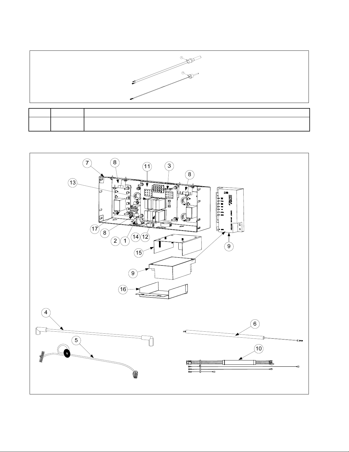
1.5 Electronics and Electrical Components
1.5.1 High-Limit Thermostat and Temperature Probe
ITEM PART # COMPONENT
√ 1 8261177
√ 2 8262900 Temperature Probe
√ Recommended parts.
Thermostat Assembly, HE FM High-Limit 425F/218C
1.5.2 Component Boxes
1-4
Page 9

1.5.2 Component Boxes cont.
ITEM PART # COMPONENT
1 8101164 Block, One-Piece Screwless Terminal
2 8160217 Insulation, Terminal Block Paper
3 8073843 Fuse 3A 250V Domestic
√
8073293
4 8075008 Cable, 21-inch Ignition (Domestic, Australia)
√
* 8075009 Cable, Ignition 19” (CE)
* 8075266 Cable, Ignition, (Australia)
* 8073484 Connector, Rajah
5 8075165 Cable, 20-pin Controller to 15-pin Interface Board – SMT
6 8066085SP Wire Assembly, Ignitor
7 2206102 Box, One-Piece Component
8 8071683 Relay, 15A 12VDC Blower, OIB, Reset Switch
√
√
9 8075691† Ignition Module, Single-Spark Capable Control (CE, Non-CE, CSA and AGA)
√
8075664† Ignition Module, Single-Spark Fenwal (AGA), (Australia)
10 8075813 Harness, Interface Board to Ignition Module (Capable Controls)
* 1084801 Harness, Interface Board to Ignition Module (Australia)
1086057 Wire Assembly, Full Vat Right (Honeywell)
1086059 Wire Assembly, Full Vat Left (Honeywell)
1086058 Wire Assembly, Dual Vat (Honeywell)
11 8262264 Interface Board Kit SMT
√
8074330 Speaker Adapter Harness SMT
8074343 Wire Harness, SMT Interface Board to Ignition Module
8064973 Interface Board – Australia Only
12 8070833
√
13 8070834
√
14 8102243 Spring, Relay Retaining
15 1086052 Plate, Ignition Module
16 8242090 Cover, Ignition Module
17 8074812
8074934
* 1060531SP Fuse Assembly, Inline (not used on all models)
* 8072659 Switch, Momentary (Control Power Reset, only used in far left component box)
* 8074403 Speaker SMT
* Not illustrated.
√ Recommended parts.
8070012 Relay, 18A 24VAC Between OIB Time Delay Board and Gas Valve, (Australia)
Fuse 5A 125V International Only
Relay, DPDT 5A 12VDC Latch (See NOTE 1.)
Relay, SPDT 15A 12VDC Basket Lift (See NOTE 2.)
Relay, 7-second Time Delay 120V (U.S., Canadian and Mexico units)
Relay, 7-second Time Delay 220V, 230V, 240V and 250V units (International units)
† For Full-vat and Dual-vat units, use two Single Spark Ignition Modules.
NOTE 1: In full-vat units, only two latch relays (Item 12) are used, located in the sockets on the right side of the
interface board. These relays are located in the bottom sockets of the interface board and control the heating
circuit.
NOTE 2: The relays in the top sockets control the basket lifts.
1-5
Page 10
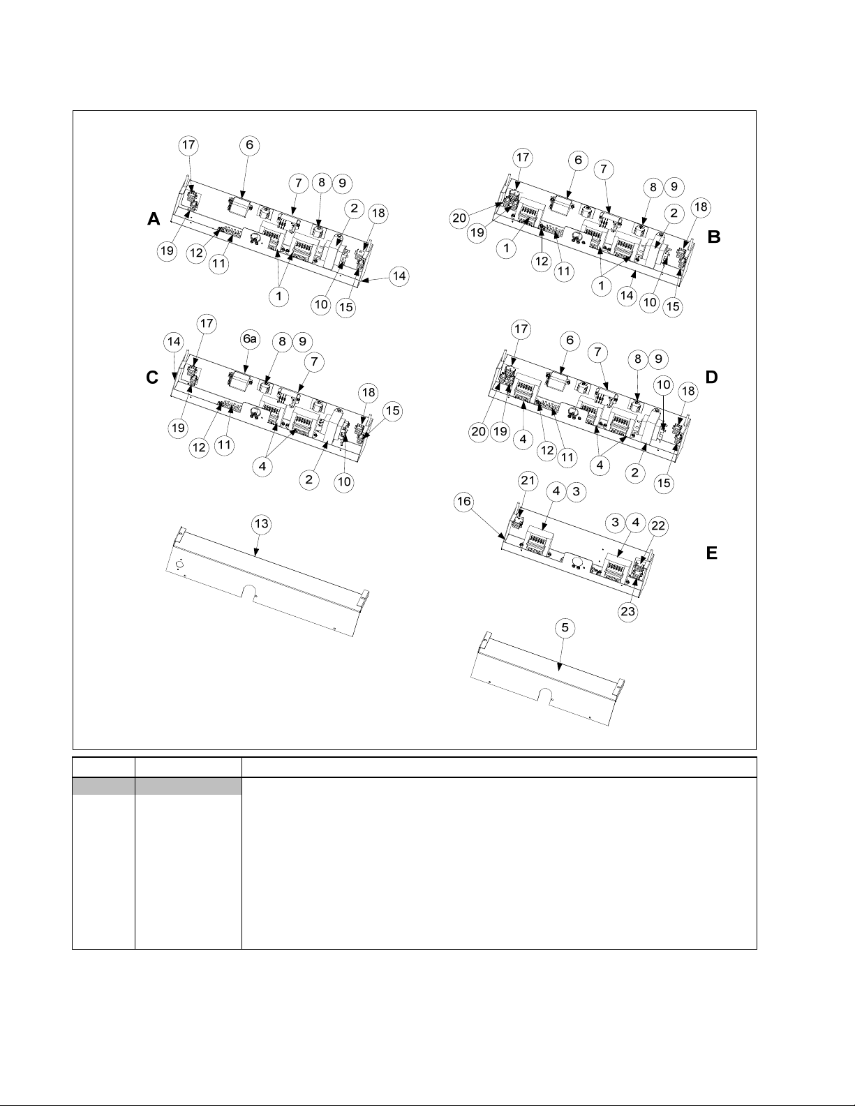
1.5.3 Transformer Boxes
ITEM PART # COMPONENT
Box Assembly, Transformer
A 1085658 GL230 and 430 (430 has added cordset 1081788) (use 1085885 Solid Shortening)
B 1085746 GL330 (use 1085886 Solid Shortening) (530 has added cordset 1081788)
C 1085808 GL230 CE Export (430 has added cordset 1081788) (use 1085890 Solid Shortening)
D 1085809 GL330 CE Export (use 1085891 Solid Shortening) (530 has added cordset 1081788)
E 1085959 FQ 430/530 CE Export 100v/120v (use 1085903 for 208/222/230/240V )
1 8074978 Transformer, 100-120V24V 62VA V/F Dual Voltage
√
2 8072181 Transformer, 100-120V/24V 62VA Filter and MIB
√
3 8074978 Transformer, V&F Dual Voltage 100-120V/12V 30VA /24V 50VA
√
4 8075129 Transformer, V&F Dual Voltage 208/222/230/240V
√ Recommended parts.
1-6
Page 11
1.5.3 Transformer Boxes cont.
ITEM PART # COMPONENT
5 2206514 Cover, GL30 4-Battery Transformer Box
√
6 8074346 Relay, DPDT 20A 120VAC (Control Reset Button) (used for control power reset in
√
domestic units)
6a 8074770 Relay, DPDT 20A 240V (Control Reset Button) (used for control power reset in inter-
√
national units)
7 8074482 Relay, Filter 30A 24VDC DPDT
√
8 8160217 Insulation, Terminal Block Paper
9 8101164 Block, One-Piece Screwless Terminal
10 8071597 Fuse, 3amp Slo-Blow
√
11 8071973 Terminal, Post
12 8070070 Terminal, Ground Lug
13 2203191 Cover, Large Transformer Box
14 8236324 Box, Large Transformer/Filter
15 1068133 Cable Assembly, Transformer Box Line GL230, 330, 430, 230 and 330 CE Export
and 430 CE Export
1085895 Cable Assembly, Transformer Box Line GL230, 330, 430, 230 and 330 CE Export
and 430 CE Export Solid Shortening
16 8237638 Box, Transformer/Filter GL30 4-Battery
17 1085774 Cable Assembly, Transformer Box Filter Pump GL230, 330, 230 and 330 CE Export
1085894 Cable Assembly, Transformer Box Filter Pump GL230, 330, 230 and 330 CE Export
Solid Shortening
18 1080994 Cable Assembly, Transformer Box #1 GL230,330, 230 and 330 CE Export
19 1080995 Cable Assembly, Transformer Box #2 GL230, 330, 230 and 330 CE Export
20 1080996 Cable Assembly, Transformer Box #3 GL330 and 330 CE Export
21 1085664 Cable Assembly, Transformer Box #4 FQ430 and 530 Non-CE and CE Export
22 1085663 Cable Assembly, Transformer Box #3 FQ430 and 530 Non-CE and CE Export
23 1085662 Harness Assembly, Cord set Female
* WIR 1093 Wire Assembly, GL430/530 (used in Item E)
* WIR 0798 Wire Assembly, GL330 Transformer/Filter Box (used in Item B and D)
* WIR 0799 Wire Assembly, GL230/430 Transformer/Filter Box (used in Item A, C)
* Not illustrated
√ Recommended parts.
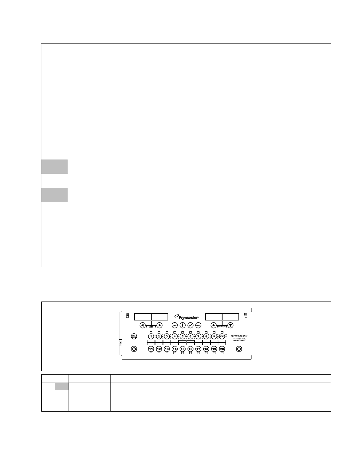
1.5.4 Controllers and Associated Components
NOTE: See Page 1-4 thru 1-5 for Interface Board to Controller Wiring Harness.
ITEM PART # COMPONENT
√ 1085780SP Controller, FilterQuick™
* 8262458 Speaker SMT
* 2600635 Bezel 2, 4 and 5 battery
* 2600684 Bezel 3 and 5 battery
* Not illustrated.
√ Recommended parts.
1-7
Page 12
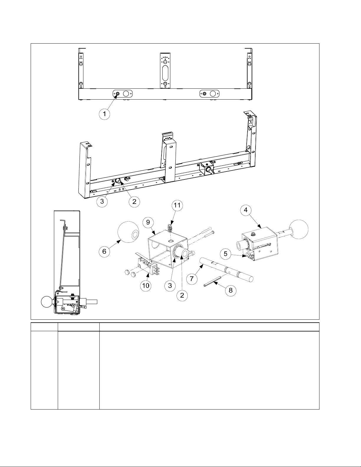
1.5.5 Control Panel Frames and Push Pull Rod Assembly
ITEM PART # COMPONENT
1 1085672 Harness, FilterQuick Drain with Light
2 8104345
3 8091107
Bushing, ⅜” Shaft Flanged Sleeve Bronze
Ring, ⅝” External Slef Locking Retaining
4 1085731 Assembly, Rod Push Pull
5 8071942 Terminal, Flag
6 8104399 Knob, 1.375“ Ball
7 8104360 Rod, Push Pull
8 8104362
Pin, ⅛” x 1.50 SS Slotted Spring
9 8238864 Support, Rod Push Pull
10 8074936 Microswitch, Gold Plated
11 8104397 Plunger, ¼-20 SS Ball Nose Spring
1-8
Page 13

1.5.6 Control Panel Frames and Push Button Assembly
ITEM PART # COMPONENT
1 8075858 Switch, Push Button LED Blue Ring Light
2 2601264 Bezel, Fascia 2 position (2/4/5 Battery) with Button (shown)
2601265 Bezel, Fascia 3 positon (3/5 Battery) with Button (not shown)
* 8263280 Kit, FQ 2- Battery Conversion from Handles to Push Button
* 8263281 Kit, FQ 3- Battery Conversion from Handles to Push Button
* 8263282 Kit, FQ 4- Battery Conversion from Handles to Push Button
* 8263284 Kit, FQ 5- Battery Conversion from Handles to Push Button
* Not illustrated.
1-9
Page 14

1.6 Wiring
1.6.1 Controller, MIB, AIF, ATO Wiring Harnesses and Cord sets (Refer to wiring diagram on page
1-59 in Service Manual 8197109.)
ITEM PART # COMPONENT
* 8074546 Controller Communication (used from Controller to Controller)
* 8074547 AIF Communication/Power (used from AIF to AIF and AIF to ATO)
* 8074850 Communication/Power (used from MIB to AIF)
* 8075780 MIB Power/Pan Sw (used from Transformer and Fltr Rly to MIB and Pan Sw)
* 8075789 Harness, MIB -Bulk connector
* 8074655 FV/DV Harness RTD Extension 20” (used from RTD to ATO Board)
* 8074845 FV/DV Harness RTD Extension 28” (used from RTD to ATO Board)
* 8262706 FV/DV ATO/RTD Probe Kit
* 8074621 FV/DV Harness RTD Short (used from RTD to ATO Board)
* 8074771 ATO Power (used from Transformer to ATO Board)
* 1069544 ATO Power to Secondary ATO box (4 and 5 battery only)
* 8074671 ATO Pump/JIB Reset/Bulk Fresh Oil Solenoid Harness
* 8074843 ATO Pump/JIB Reset Harness Non-Bulk
* 1068977 Long Top-off Power (used between Transformer Box to ATO Box) Domestic
* 1081589 Long Top-off Power (used between Transformer Box to ATO Box) CE and Export
* 8074657 Jumper (used on 4 and 5 battery ATO board plug J5 pin 7 and 8)
* 8074573
* 8074552
Controller Locator Wire (used from Controller to Interface Board) See wiring dia-
gram 8051978 for locator pin positions.
Communications Terminator (used on Controller pin J6 and ATO board pin J10 to
terminate network)
* 8067742SP Cord set, 120V Fryer and Motor with Ring Terminals
* 1060516 Cord set, 220-250V CE/Export Fryer and Motor with Ring Terminals
√ * 8074660PK SMT Pin Service Repair Kit
√ * 2302345 SMT Pin Extractor
* Not illustrated.
√ Recommended parts.
See page 1-26, 1-31, 1-39 and 1-51 in Service Manual 8197109 for Pin Positions.
1-10
Page 15

1.6.2 Main Wiring Harnesses
ITEM PART # COMPONENT
1
2
8075776 Main Wiring Harness Vat 1
8122164 Main Wiring Harness Vat 1 Australia
8075779 Main Wiring Harness Vat 2-5
8072165 Main Wiring Harness Vat 2-5 Australia
1-11
Page 16

1.7 Frypots and Associated Components
1.7.1 Full-Vat Frypot Components
NOTE: All insulation and
gaskets can be ordered in
a single kit, P/N 826-2595.
Kit 826-2592 contains the
insulation and gaskets re-
quired when replacing
burners.
1-12
Page 17

1.7.1 Full-Vat Frypot Components cont.
ITEM PART # COMPONENT
1081752SP Frypot Assembly Full-Vat (NAT/PRO)
8262595 Insulation Kit, Complete Full-Vat
8262592 Insulation Kit, Burner Full-Vat
1 1080925 Flue Assembly, Full-Vat
2 8238175 Back, Lower Full-Vat Combustion Chamber
3 2206529 Retainer, Full-Vat Upper Insulation (modified from shown, now one piece)
4 2207834 Retainer, Outer Frypot
5 2306960 Plate, FV Collector Mounting
6 2202851 Brace, FV Rear Insulation
7 2202920 Brace, Foam Deck Insulation
√ 8 8103435 Burner, Universal Replacement
9 8120356 Insulation, Burner Sight Glass
10 8160900 Insulation, Burner
11 8120706 Insulation, Upper Burner Rail
12 8121029 Insulation, Combustion Chamber Side
13 8140048SP Glass, Burner Sight
14 8160837 Insulation, FV Rear Lower
15 8160731 Insulation, FV LH/RH Front Seal
16 8160976 Insulation, FV Lower Inner Front
17 8160733 Insulation, FV Front Upper
18 8160978 Insulation, FV Outer Front
19 8160746 Insulation, Foam Deck
20 8237644 Frypot, FV 30 439 SS
21 8238193 Retainer, FV LH Upper Burner
22 8238194 Retainer, FV RH Upper Burner
23 8238571 Retainer, FV Front Combustion Insulation
24 8238574
25 8242164 Front Upper Seal Weldment, FV LH
26 8242165 Front Upper Seal Weldment, FV RH
27 9001031 Retainer, Burner Sight Glass
28 9300818 Bracket, Flue to Pot
29 9004253 Strip, Fluecap Retainer
30 9001049 Retainer, Plenum Gasket
31 8160057 Gasket, Plenum
* 8160981 Gasket, Ignitor
* 9102474 Pot-to-Pot Gap Clip
* Not illustrated.
√ Recommended parts.
Plenum, Full-Vat (use 1081533 for CE units) (use 1082553 for Export Non-CE
units)
1-13
Page 18

1.7.2 Dual-Vat Frypot Components
NOTE: All insulation and
gaskets can be ordered
in a single kit, P/N 826-
2596. Kit 826-2593 contains the
insulation and gaskets
required when replacing
burners.
1-14
Page 19

1.7.2 Dual-Vat Frypot Components cont.
ITEM PART # COMPONENT
* 1081753SP Frypot Assembly Dual-Vat (NAT/PRO)
* 8262596 Insulation Kit, Complete Dual-Vat
√ * 8262593 Insulation Kit, Burner Dual-Vat
1 1080926 Flue Assembly, Dual-Vat
2 1067960 Plate Assembly, Dual-Vat Collector
3 2206530 Retainer, Dual-Vat Upper Insulation
4 2207835 Retainer, Dual-Vat Outer Frypot
5 8238176 Back, Dual-Vat Lower Combustion Chamber
6 2202920 Brace, Foam Deck Insulation
7 2202972 Brace, Dual-Vat Rear Insulation
√ 8 8103435 Burner, Universal Replacement
9 8120356 Insulation, Burner Sight Glass
10 8160900 Insulation, Burner
11 8120706 Insulation, Upper Burner Rail
12 8121029 Insulation, Combustion Chamber Side
13 8140048SP Glass, Burner Sight
14 8160838 Insulation, Dual-Vat Rear Lower
15 8160741 Insulation, Dual-Vat LH/RH Front Seal
16 8160977 Insulation, Dual-Vat Lower Inner Front
17 8160743 Insulation, Dual-Vat Front Upper
18 8160979 Insulation, Dual-Vat Outer Front
19 8160746 Insulation, Foam Deck
20 8120688 Insulation, Flue Collection
21 8238196 Retainer, Dual-Vat RH Upper Burner
22 8238195 Retainer, Dual-Vat LH Upper Burner
23 8238578 Retainer, Dual-Vat Front Insulation
24 8238576 Retainer, Dual-Vat Outer Front
25 8241796 Riser W/A Dual-Vat Pot
26 8242166 Dual-Vat LH Upper W/A Seal
27 8242167 Dual-Vat RH Upper W/A Seal
28 9001031 Retainer, Sight Glass
29 9300818 Bracket, Flue to Pot
30 9004253 Strip, Fluecap Retainer
31 9001049 Retainer, Plenum Gasket
32 8160057 Gasket, Plenum
* 8160981 Gasket, Ignitor
33 8238573
34 8237645 Frypot, Dual-Vat 30 439
* 9102474 Pot-to-Pot Gap Clip
* Not illustrated.
√ Recommended parts.
Plenum, Dual-Vat (use 1081534 for CE units) (use 1082554 for Export Non-CE
units)
1-15
Page 20

1.7.3 Frypot Assemblies and Associated Parts
1
10
12
11
2
13
4
6
3
3
5
44
6
9
8
7
Full Vat Dual Vat
ITEM PART # COMPONENT
1 1081752SP Frypot Assembly, Full-Vat Natural/Propane
2 1081753SP Frypot Assembly, Dual-Vat Natural/Propane
√ 3 8074961 Actuator, Rotary 24VDC (#1) Blue
√ 4 8074962 Actuator, Rotary 24VDC (#2) Black
√ 5 8103755 Valve, 1¼ Drain Rotary Actuator
√ 6 8103754 Valve, ½ NPT Return Rotary Actuator
7
8
9
√ 10 8262706 Probe, RTD AIF/ATO Kit
√ 11 8263196 Probe, Temperature Kit
√ 12 8074815 Sensor Assy, Oil 120V
8074947 Sensor Assy, Oil 220V
8074935 Sensor Assy, Oil 230V
8074942 Sensor Assy, Oil 240V and 250V
√ 13
√ Recommended parts.
8130062
8101668
8101055
8261177
Elbow, Street ½” 90 BM
Adaptor, Male ⅝” OD x ½”
Flexline, ⅝” OD x 11.50” Long
Thermostat Assembly, HE High-Limit 425F/218C Standard
10
11
12
13
5
4
1-16
Page 21

1.8 Oil Return Manifolds
ITEM PART # COMPONENT
1 8103275 Manifold, Two-Station Fryer
2 8103245 Manifold, Three-Station Fryer
3 8103368 Manifold, Four-Station Fryer
4 8103824 Manifold, Five-Station Fryer
* 8130907 Cap, 15/16” Valve
* Not illustrated
1.9 Return Valve
Full-Vat or DualVat Return Valve
ITEM PART # COMPONENT
1 8103754 Valve, ½” NPT Rotary Actuator
1-17
Page 22

1.10 Gas Supply and Combustion System Components
1
See pages 1-10 through 1-13
for burners and burner insulation part numbers.
5
2
3
4
Full Vat Gas Manifold (Typical)
The example illustrated is typical of
gas manifolds. Each manifold is
assembled from standard 1/2-, 3/4-,
and 1-inch NPT black iron pipe
nipples, elbows, tees, plugs, and
unions, which may be locally
acquired.
1-18
See Page 1-18 – 1-19 for details of gas
valves and related components.
Page 23

1.10 Gas Supply and Combustion System Components cont.
ITEM PART # COMPONENT
√ 1 Ignitor
8263053 Natural Gas (G20, G25) (includes gasket 8160981, which may be ordered sepa-
rately)
8262994 Propane (G30, G31) (includes gasket 8160981, which may be ordered separately)
√ 2 Blower Assembly, Combustion Air (includes harness and Item 3)
1062997SP 115V 50/60 Hz (Right)
1062999SP 100V 50/60 Hz (Right)
1083307SP 220V 60 Hz (Right)
1062998SP 208-240V 50/60 Hz (Right) Non-CE International
1082360SP 230V 50Hz CE FV Australia
1082361SP 230V 50Hz (Right) CE DV Australia
1063001SP 230V 50/60 Hz CE (Right) CE (Wide Body)
3 8160554 Cover, Blower Motor (component of all blowers listed above)
* 8068806SP Harness Assembly, Blower Motor (component of all blowers listed above)
4 Orifice, Burner
8103977 1.88mm 75% Butane/25% Butane (Standard Elevation)
** 8103865 1.95mm Propane/Butane (G30, G31) Australia Only
** 8103860 2.05 mm Propane/Butane (G30, G31) (0-4999 Ft, 0-1524 M)
** 8103863 2.10 mm Propane/Butane (G30, G31) (5000-9000 Ft, 1525-2743 M)
** 8103867 2.84mm Natural Gas (G20, G25) Australia Only DV
** 8103866 2.92mm Natural Gas (G20, G25) Australia Only FV
** 8103864 3.18 mm Natural Gas (G20, G25) (0-4999 Ft, 0-1524 M) CE
** 8103861 3.26 mm Natural Gas (G20, G25) (0-4999 Ft, 0-1524 M)
** 8103862 3.40 mm Natural Gas (G20, G25) (5000-9000 Ft, 1525-2743 M)
√ 5 1083346 Switch, Air Pressure Assembly FV (8122226 switch alone) CE and Export
√ 1081455SP Switch, Air Pressure Assembly DV (8122141 switch alone) CE and Export
√ 1083542 Switch, Air Pressure Assembly FV (8122226 switch alone) Australia
√ 1083541 Switch, Air Pressure Assembly DV (8122141 switch alone) Australia
* Not illustrated.
√ Recommended parts.
**NPT Threads
1-19
Page 24

1.11 Gas Valves and Associated Components
1-20
Page 25

1.11 Gas Valves and Associated Components cont.
ITEM PART # COMPONENT
√ 1 Valve, Non-CE Gas
8261122 Natural Gas (G20, G25)
8261120 Kit Natural Gas w/ flexlines and hardware
8261123 Propane Gas (G30, G31)
8261121 Kit, Propane Gas w/ flexlines and hardware
√ 2 8101715 Valve, CE Gas (G20, G25, G30, G31)
* 8069678 Plug, Gas Valve CE
3 8101041 Accessory Kit (contains parts to adapt Item 2 to specific fryer configuration)
4 8100691
Tube, ⅛” Vent
5 8100494 Ferrule (Nut), Orifice
6 8101355
7 8101354
8101353
8 8110800
9 8130301
10 8130302
Gas Line, ⅜” OD X 15-inch SS Flexible
Gas Line, ⅜” OD X 12-inch SS Flexible
Gas Line, ⅜” OD X 9-inch SS Flexible (Used on some split pots)
Tube, ⅛” OD X 12.5-inch Enrichment (cut and form to fit)
Tee, ¼” Male NPT to ⅜” Tube
Elbow, ¼” Male NPT to ⅜” Tube 90° (used on DV valve)
11 8130304 Bushing, ½” NPT to ¼” NPT Flush Reducing
12 8130405
13 8130378
14 8130340
15 8130154
16 8101176
17 8130377
18 8130354
19 8130016
20 8101006
Nipple, ⅛” NPT X 2.00-inch Brass
Fitting, ⅛” NPT Cross
Adapter, ⅛” NPT to ⅛” Tube
Plug, ⅛” NPT Hex Head Pipe
Tap, ⅛” NPT Pressure
Tee, ⅛” NPT Female
Elbow, ⅛” NPT X ⅛” Tube Compression
Nipple, ⅛” NPT X Close
Bushing, ¼” NPT to ⅛” NPT Reducing
21 8130495 Tee, ¼” Male NPT to Female NPT
22 8101025
Connector, ¼” Male NPT to ⅜” Tube
23 8101026 Tee, ¼” Male NPT to Female NPT Street
24 8130700 Nipple, ¼” NPT x 3.00-inch Brass
* 8130472 Nipple, ¼” NPT x 2.50-inch Brass
* 8130471 Nipple, ¼” NPT x 1.50-inch Brass
* 8130473 Nipple, ¼” NPT x 4.00-inch Brass
25 8103147 Bushing, ¾” OD x ½” ID NPT Flush
26 8103807
Tube, ⅛” OD X 6.5-inch Enrichment
* 8130507 Coupling, ¼” NPT Brass
27 8130449 Tee, ¼” NPT Brass
√ Recommended parts.
* Not illustrated.
1-21
Page 26

1.12 Filtration System Components
Pump plumbing may differ somewhat from
illustration depending on configuration and
date of manufacture.
ITEM PART # COMPONENT
1 8238786 Lid, Filter Pan
2 8238626 Crumb Tray
3 8103289 Hold-Down Ring for Pad 11.20 x 19.10
4 8122025 Sana Grid Filter Screen
5 1085758SP Pan, Filter with casters
√ 5a 8261392 O-Ring (Pkg. of 5; used with Item 5)
5b 8130568
6 8236458 Suction Tube
7 8103007 Magnet, Pull Ring
* Not illustrated.
√ Recommended parts
Plug, ⅛” Socket Head Pipe (used with Item 5; two required)
1-22
Page 27

1.12 Filtration System Components cont.
ITEM PART # COMPONENT
8 1085626 Assembly, Filter Pan Switch
√ * 1065876SP Sensor, Magnet
9 2318372 Rail, Upper
9a 2308373 Rail, Lower
10 8238030 Support, Left Filter Pan
11 2208368 Support, Right Filter Pan (use 1082872 for 2- Battery)
√ 12 Motor and Gasket Kit
8261785 100V 50/60 Hz
8261712 115V 50/60 Hz
8261756 208V 50/60 Hz
8261270 220-240V 50/60 Hz
8261755 250V 50/60 Hz
√ 13 8263191 Pump and Gasket Kit, 4 GPM
8160093 Gasket, Pump/Motor
* 8091062 Cap Screw, 5/16”-18 4.00” NC Hex (Connects pump to motor.) (use 8090194 washer)
14 8130062 Elbow, ½” 90° BM
15 8101668
16 8101067
17 8101369 Flexline, 17.50-inch Oil Return
18 8130087 Nipple, ½” x 1.50-inch NPT BM
19 8130298 Nipple, ½” x 2.00-inch NPT BM
20 8100667 Check Valve ½” NPT
21 2206191 Brace, Pump Motor
22 8104137 Caster, 2.00-inch
23 8130331 Elbow, ½” NPT with Side Outlet BM
24 8103738 Adapter, Check Valve Close
25 8101669
* 8071105 Heater Strip Assembly, 100120V 25W 18”
* 8071098 Heater Strip Assembly, 208-250V 25W 18”
* Not illustrated. √ Recommended parts.
Adapter, ⅝” to ½” NPT Male
Flexline, ⅝” OD x 8.50-inches long Oil Return
Adapter, Female ⅝” OD x ½”
1.13 Filtration Electronic Components
1.13.1 MIB (Manual Interface Board) Assembly
ITEM PART # COMPONENT
1 2206554 Cover, MIB
√ 2 1085723SP Assembly, FilterQuick MIB Controller w/ Metalwork (use 8074481 for overlay)
* 8160819 Seal, MIB
3 2206661 Mounting Plate
4 8091021 Screw, 10x 3/8 Torx Pan
* Not illustrated. √ Recommended parts.
1-23
Page 28

1.13.2 AIF (Automatic Intermittent Filtration) Actuator Board Assembly
108-5721 AIF Actuator Board Assembly
ITEM PART # COMPONENT
√ 1085721 AIF Assembly FilterQuick
1 8241991 Cover, Actuator Board
2 8160814 Gasket, Actuator Board
3 8160815 Gasket, Controller Board
4 1085720 Board, AIF Actuator FilterQuick
5 8160820 Seal, Actuator Board
6 1080097 Box, Actuator Stud
√ Recommended parts.
1.14 ATO (Auto Top-Off) Components
1.14.1 JIB Cradle, JIB Box, JIB Cap/ Pick-Up Assembly and ATO Board Assemblies
ITEM PART # COMPONENT
1 2600197 Cradle, JIB Gas
* 8090402 Screw, Thumb ¼-20 x ½”
2 8242298 Box, JIB
3 1082005SP Cap, JIB Assembly (use 1082047 for Intl BIB)
4 1082001 Cap, JIB (use 1082002 for Intl. BIB)
5 8160870 Clamp
6 8103823 Hose, JIB
7 8237738 Tip Assembly, JIB Suction Hose
8 1085719 Box, Topoff Assembly FilterQuick 120V
9 1085764 Box, Topoff Assembly FilterQuick 208-240V
10 1085718 Box, Auto Top Off Board (use 2205679 for ATO Box Cover)
√ 11 1085717 PCB Board, Automatic Top Off
√ 12 8072181 Transformer, 100-120V/24V 62VA
√ 13 8070855 Transformer, 120V 50/60-12V 20VA
√ 14 8072180 Transformer, 208-240V/24V 50VA
√ 15 8072191 Transformer, 208/230/240 -12V 30VA
16 8071321 Holder, Fuse AGC Panel Mount ¼”
√ * 8071597 Fuse, 3A Slow-Blow
√ 17 8070012 Relay, 18AMP 1/3 HP 24V Coil (Top off pump)
* Not illustrated. √ Recommended parts.
NOTE: Top off boxes for vats 4 and 5 have either item 12 or item 14, both have item 11.
1-24
Page 29

1.14.2 ATO Pump Assembly Non-Bulk
Semi/Solid Shortening
Liquid Shortening
See page 1-22 for
JIB or BIB hose
that connects here.
See page 1-25 for
solid shortening
inlet plumbing
ITEM PART # COMPONENT
√ 1 1080639 Pump, Shurflo 24VAC (use 1085673 for CE)
2 8103263 Flexline, ½” OD x 36-inch (use 8103375 17-inch for 2-battery) (Out to top off
manifold)
3 8101369
4 1083403 Fitting, Shurflo Pump with female end (includes O-rings)
5 1082054 Fitting, Shurflo Pump with male end (includes O-rings)
6 8160782 O-Ring, Viton #111
7 8130940
8 8130062 Elbow, ½” 90° BM
9 8101668
10 8101669
√ Recommended parts.
Flexline, ⅝” OD x 17.50-inch (use 8101069 29.50-inch for 2-battery)
Elbow, ¼” NPT x ⅜” Flare
Adapter, ⅝” to ½” NPT Male
Adapter, Female ⅝” OD x ½”
1-25
Page 30

1.14.3 ATO Pump Assembly Bulk
m
TO OIL RETURN
MANIFOLD
Item 2 connects to a check
2
valve before going into
the oil return
anifold.
3
1
TO BULK OIL MANIFOLD (TO FILL POT)
4
IN FROM BULK
OIL FILL
COUPLING
18
17
18
14
12
16
20
TO/FROM JIB
19
8
14
21
5
15
14
11
9
7
10
6
INSTALL
O-RINGS
HERE
11
22
23
13
12
ITEM PART # COMPONENT
1085790 Pump, Assy FQ230 Bulk ATO (use 1085791 for FQ330 bulk oil ATO)
√ 1 1080639 Pump, Shurflo 24VAC
2 8103263 Flexline, ½” OD x 36-inch (Out to oil check valve and to return manifold) 3, 4 and 5 vat
8103375 Flexline, ½” OD x 17-inch (Out to oil check valve and to return manifold) 2 vat
* 8100667 Check valve, ½ NPT 1 PSI
3 8101055
4 8101369
Flexline, ⅝” OD x 11.50-inch (Inlet to Top Off Pump)
Flexline, ⅝” OD x 17.50-inch
5 1066830 Solenoid
6 8130940
Elbow, ¼” NPT x ⅜ Flare
7 1083403 Fitting, Shurflo Pump with female end (includes O-rings)
8 8130530 Tee, Reducing ½” x ¼” x ½” (JIB hose connects here)
9 1082054 Fitting, Shurflo Pump with male end (includes O-rings)
10 8160782 O-Ring, Viton #111
11 8130062 Elbow, ½” 90° BM
12 8130165 Elbow, Street ½” x ½” NPT 90° BM
13 8130304 Bushing, BM Flush
14 8101668
Adaptor, Male ⅝” OD x ½”
15 8130838 Nipple, ¼” NPT BM Close
16 8130003 Tee, ½” x ½” x ½” BM
17 8103583 Check Valve ½” NPT 4 PSI
18 8103738 Adapter, Check Valve Close NPT
19 8101669
Adapter, Female ⅞” OD x ½”
20 8130022 Nipple, ½” x Close NPT BM
21 8130537 Nipple, ¼” x 2.00” NPT
22 1069206 Assembly, JIB Reset Button Bracket
23 8074678 Switch, Momentary JIB Reset
* Not illustrated.
√ Recommended parts.
1-26
Page 31

1.14.4 Shortening Melting Unit
ITEM PART # COMPONENT
1084497SP Assy, Heated Shortening 120V (use 1084493 240V) (use 1085585 100V)
1 1084496 Box Assy, Heated Shortening 120V(use 1084492 240V)(use 1085584 100V)
2 1083774 Assembly, Solid Shortening Lid
3 8103957 Pan, Heated Shortening
4 8075321 Strips, Hot Box Heater with controller 120V
8075268 Strips, Hot Box Heater with controller 240V
8075732 Strips, Hot Box Heater with controller 100V
5 8100180 Handle
√ 6 8261392 O-Ring (Pkg. of 5)
7 8130568
8 8238319 Bracket W/A, Shortening Suction 3 battery
9 8101669
10 8101055
11 8160782 O-Ring, Viton #111
12 8130908 Adapter, ½” NPT 90°
13 1082054 Fitting, Shurflo Pump with male end (includes O-rings)
14 8071321 Holder, Fuse
√ * 8071555 Fuse 5 Amp 240V
√ * 8072799 Fuse 10 Amp 120V
15 8074036 Switch
* 8071105 Heater Strip Assembly, 120V, 25W 18”
* 8071420 Heater Strip Assembly, 120V, 25W 36”
* 8071472 Heater Strip Assembly, 120V, 40W 56”
* 8071098 Heater Strip Assembly, 240V, 25W 18”
* 8071419 Heater Strip Assembly, 240V, 45W 36”
* 8071473 Heater Strip Assembly, 240V, 70W 56”
* 8071915 Heater Strip Assembly, 100V, 25W 18”
* 8071917 Heater Strip Assembly, 100V, 40W 56”
* Not illustrated.
√ Recommended parts.
Plug, ⅛” Socket Head Pipe
Adaptor, Female ⅞” OD x ½”
Flexline, ⅝” OD x 11.5-inch
1-27
Page 32

1.15 Bulk Oil System Components
1.15.1 Bulk Dispose Waste Valve and Test Box
ITEM PART # COMPONENT
1086009 Valve, Bulk Dispose Waste FQ
1 1086008 Bracket, FQ Bulk Waste Valve
2 2205899 Handle, Bulk Waste Valve
3 8074936 Microswitch, Gold Sealed
4 8100278 Valve, ½” Ball
5 9002935 Retainer, Nut Return Valve
6 9012348 Cover, DV Safety Switch
7 9022348 Cover, DV Safety Switch
8 8160220 Insulation, RF Switch
9 1080716 Box, Bulk Test
1-28
Page 33

1.15.2 Bulk Oil Manifold and Accessories
1-29
Page 34

1.15.2 Bulk Oil Manifold and Accessories cont.
ITEM PART # COMPONENT
1 8103531 Valve, Check 20PSI
2 1086009 Valve, Bulk Waste Assembly (see page 1-26 for parts)
3 8101669
4 8075789 Harness, FilterQuick Gas Bulk – MIB connection
5 8101668
6 8101057
7 8101055
8 8101067
9 8130022 Nipple, ½ ” x Close NPT BM
10 8130251 Nipple, ½” x 4.50-inches NPT BM (not shown in illustration – connects between
11 8130087 Nipple, ½” x 1.50-inch NPT BM
12 8103270
13 8130003 Tee, ½” x ½” x ½” BM
14 8103738 Adaptor, Check Valve Close Nipple
15 8130304 Bushing, ½” x ¼”
16 8103160 Adaptor, ½ ” NPT x 15/16”
17 8130062 Elbow, ½” BM 90°
18 8100667 Valve, Check ½” NPT 1 PSI Bulk Manifold
19 8237838 Bracket W/A, Gas Bulk Fresh Oil
20 8130298 Nipple, ½” x 2-inches NPT BM
21 8238827 Bracket W/A, FQ Gas Bulk Dispose
1080686SP Handle and Lock Assy, Gas Bulk
22 8090657 Clip, Clevis Right Rod End
23 2205656 Brace, Bulk Handle
24 2205657 Cover, Bulk Handle
25 8237208 Handle, Gas Bulk Waste Pull
26 8103587 Lock, Bulk Waste Handle (includes keys)
27 8130342 Elbow, Street 45° ½” NPT
28 8130463 Plug, ½ ” NPT
Adaptor, Male ⅝” OD x ½”
Adaptor, Male ⅝” OD x ½”
Flexline, ⅝” OD x 13-inches long
Flexline, ⅝” OD x 11.50-inches long
Flexline, ⅝” OD x 8.50-inches long
item 17 and item 3)
Fitting, ⅜” Flare x ¼” NPT
1-30
Page 35

1.16 Basket Lift Assy and Associated Parts
1-31
Page 36

1.16 Basket Lift Assy and Associated Parts cont.
ITEM PART # COMPONENT
1061807SP Basket Lift Assy, 100-120VAC w/Relay (Items 1-20) shown
1061805SP Basket Lift Assy, 200-220VAC w/Relay (Items 1-20) shown
* 1061810SP Basket Lift Assy, 230-250VAC w/Relay (Items 1-20) not shown
1 8101012 Rod, Basket Lift
2 8130035 Bushing, Bronze
3 8072513 Capacitor, 12.5 μFd 330VAC
4 9018499 Chassis, Left Basket Lift
5 9028499 Chassis, Right Basket Lift
6 8070159 Connector, 12-Pin Female
7 9005529 Gusset, Basket Lift Motor
8 8120442 Insulation, Microswitch
9 8072572 Microswitch
10 8065964SP Motor Assy, 208-240VAC Modular Basket Lift
11 2002942 Mount, Modular Basket Lift
12 8071683 Relay, 12VDC
13 Resistor Assy
8068530SP
1062770SP 208-220VAC Modular Basket Lift
* 1062771SP 230-250VAC Modular Basket Lift
14 8090082 Ring, Bushing Retainer
15 9104776
16 8090127 Screw, ¼-20 X ½” Slotted Round Head
17 8238015 Arm, Left Basket Lift
18 8238016 Arm, Right Basket Lift
19 8100179 Button, Plug
20 1082743SP Roller Assy, Basket Lift
21 1082860 Mount, Basket Lift Roller
22 8100194 Roller, Basket Lift
23 8100374 Spacer, Basket Lift Roller
24 8090508 Bolt, ¼-20 X 1¼ “
25 8237980 Guide, Basket lift Left
26 8238023 Guide, Basket lift Right
27 8090990 Nut, ¼-20 Cap
* 8241477 Tray, Drip Right
* 8241476 Tray, Drip Left
* 1083454 Harness, Gas BL Interface
* 8073695 Basket Lift Cable
* WIR0482SP Wire Bundle, 100-120VAC Basket Lift
* 1061822SP For 100-120V Modular Basket Lift
* 1061804SP For 208-250V Modular Basket Lift
* Not illustrated.
Basket Lift Assemblies (see Note 1 in illustration)
100-120V Modular Basket Lift (see Note 2 in illustration)
Cover, Modular Basket Lift Rear S/S (Use 9004776 for Mild Steel)
Wire Assemblies
1-32
Page 37

1.17 Oil Quality Sensor (OQS) and Associated Parts
7
12
8
6
9
1
2
11
10
3
4
5
ITEM PART # COMPONENT
8263291 Kit, OQS FilterQuick Gas 2-Battery (Kit to add to existing FilterQuick Gas Fryers)
8263294 Kit, OQS FilterQuick Gas 3, 4 and 5 Battery (Kit to add to existing FilterQuick Gas Fryers)
1 8263292 Sensor, FilterQuick OQS Replacement
2 8101055
3 2401385 Retainer, OQS Sensor FQ
4 2401386 Brace, OQS Sensor Mount
5 2401384 Mount, OQS Sensor FQ
6 8238335 Screen, Suction Line Filter
7 8238903 Body W/A, Pre-Filter Final EBRO BIGL230
8 8104167 Lanyard, In-Line Filter
9 8101369
10 8101067
8101369
11 8101668
12 2401086 Wrench, Pre-Filter Cap
Flexline, ⅝” OD x 11.5-inch
Flexline, ⅝” OD x 17.50-inch
Flexline, ⅝” OD x 8.50-inch 2- Battery
Flexline, ⅝” OD x 17.50-inch 3, 4 and 5-Battery
Adapter, ⅝” to ½” NPT Male
1-33
Page 38

8700LINEAVENUE,SHREVEPORT,LA71106‐6800
FRYMASTER
EMAIL:SERVICE@FRYMASTER.COM
WWW.FRYMASTER.COM
318‐865‐1711
844‐724‐CARE(2273)
*8197116*
Every new piece of Manitowoc Foodservice equipment comes with KitchenCare™ and you choose the level of service that meets
your operational needs from one restaurant to multiple locations.
– Warranty & lifetime service, certified OEM parts, global parts inventory, performance audited
StarCare
ExtraCare
LifeCare
Talk with KitchenCare™
To learn how Manitowoc Foodservice and its leading brands can equip you, visit our global web site at
www.manitowocfoodservice.com, then discover the regional or local resources available to you.
©2014 Manitowoc Foodservice except where explicitly stated otherwise. All rights reserved. Continuing product improvement may necessitate change of specifications without notice.
Part Number FRY_P_8197116 08/2015
– CareCode, 24/7 Support, online/mobile product information
– Install & equipment orientation, planned maintenance, KitchenConnect™, MenuConnect
- 1-844-724-CARE - www.mtwkitchencare.com
 Loading...