

Page 1
45 Series Gas Fryers
Service & Parts Manual
Frymaster, a member of the Commercial Food Equipment Service Association, recommends
using CFESA Certified Technicians.
24-Hour Service Hotline 1-800-551-8633 NOVEMBER 2003
*8195665*
Page 2
NOTICE
IF, DURING THE WARRANTY PERIOD, THE CUSTOMER USES A PART FOR THIS ENODIS
EQUIPMENT OTHER THAN AN UNMODIFIED NEW OR RECYCLED PART PURCHASED
DIRECTLY FROM FRYMASTER/DEAN, OR ANY OF ITS AUTHORIZED SERVICE CENTERS,
AND/OR THE PART BEING USED IS MODIFIED FROM ITS ORIGINAL CONFIGURATION, THIS
WARRANTY WILL BE VOID. FURTHER, FRYMASTER/DEAN AND ITS AFFILIATES WILL NOT BE
LIABLE FOR ANY CLAIMS, DAMAGES OR EXPENSES INCURRED BY THE CUSTOMER WHICH
ARISE DIRECTLY OR INDIRECTLY, IN WHOLE OR IN PART, DUE TO THE INSTALLATION OF
ANY MODIFIED PART AND/OR PART RECEIVED FROM AN UNAUTHORIZED SERVICE CENTER.
NOTICE
This appliance is intended for professional use only and is to be operated by qualified
personnel only. A Frymaster/DEAN Factory Authorized Service Center (FASC) or other qualified
professional should perform installation, maintenance, and repairs. Installation, maintenance,
or repairs by unqualified personnel may void the manufacturer’s warranty. See Chapter 1 of
this manual for definitions of qualified personnel.
NOTICE
This equipment must be installed in accordance with the appropriate national and local codes of
the country and/or region in which the appliance is installed. See NATIONAL CODE
REQUIREMENTS in Chapter 2 of this manual for specifics.
NOTICE TO U.S. CUSTOMERS
This equipment is to be installed in compliance with the basic plumbing code of the Building
Officials and Code Administrators International, Inc. (BOCA) and the Food Service Sanitation
Manual of the U.S. Food and Drug Administration.
NOTICE
Drawings and photos used in this manual are intended to illustrate operational, cleaning and
technical procedures and may not conform to onsite management operational procedures.
NOTICE TO OWNERS OF UNITS EQUIPPED WITH COMPUTERS
U.S.
This device complies with Part 15 of the FCC rules. Operation is subject to the following two
conditions: 1) This device may not cause harmful interference, and 2) This device must accept
any interference received, including interference that may cause undesired operation. While
this device is a verified Class A device, it has been shown to meet the Class B limits.
CANADA
This digital apparatus does not exceed the Class A or B limits for radio noise emissions as set
out by the ICES-003 standard of the Canadian Department of Communications.
Cet appareil numerique n’emet pas de bruits radioelectriques depassany les limites de classe A
et B prescrites dans la norme NMB-003 edictee par le Ministre des Communcations du Canada.
DANGER
Improper installation, adjustment, maintenance or service, and unauthorized alterations or
modifications can cause property damage, injury, or death. Read the installation, operating,
and service instructions thoroughly before installing or servicing this equipment. Only qualified
service personnel may convert this appliance to use a gas other than that for which it was
originally configured.
Page 3
DANGER
Adequate means must be provided to limit the movement of this appliance without depending
upon the gas line connection. Single fryers equipped with legs must be stabilized by installing
anchor straps. All fryers equipped with casters must be stabilized by installing restraining
chains. If a flexible gas line is used, an additional restraining cable must be connected at all
times when the fryer is in use.
DANGER
The front ledge of the fryer is not a step! Do not stand on the fryer. Serious injury can result
from slips or contact with the hot oil.
DANGER
Do not store or use gasoline or other flammable liquids or vapors in the vicinity of this or any
other appliance.
DANGER
Instructions to be followed in the event the operator smells gas or otherwise detects a gas leak
must be posted in a prominent location. This information can be obtained from the local gas
company or gas supplier.
DANGER
The crumb tray in fryers equipped with a filter system must be emptied into a fireproof container
at the end of frying operations each day. Some food particles can spontaneously combust if left
soaking in certain shortening material.
WARNING
Do not bang fry baskets or other utensils on the fryer’s joiner strip. The strip is present to seal
the joint between the fry vessels. Banging fry baskets on the strip to dislodge shortening will
distort the strip, adversely affecting its fit. It is designed for a tight fit and should only be
removed for cleaning.
ii
Page 4

45 SERIES GAS FRYERS SERVICE AND PARTS MANUAL
TABLE OF CONTENTS
CHAPTER 1: Service Procedures
1.1 Functional Description....................................................................................................1-1
Pilot Ignition System.......................................................................................................1-1
Control Options...............................................................................................................1-1
Interface Boards ..............................................................................................................1-1
Thermostats and Temperature Probes.............................................................................1-3
1.2 Accessing Fryers for Servicing.......................................................................................1-4
1.3 Checking the Burner Manifold Gas Pressure..................................................................1-4
1.4 Adjusting the Pilot Flame ...............................................................................................1-5
1.5 Cleaning the Gas Valve Vent Tube ................................................................................1-6
1.6 Adjusting Burner Ceramic Target Spacing and Alignment............................................1-6
1.7 Calibrating the Thermostat Control ................................................................................1-6
1.8 Replacing Fryer Components .........................................................................................1-7
1.8.1 Replacing the Controller or Computer............................................................................1-7
1.8.2 Replacing the Operating Thermostat ..............................................................................1-8
1.8.3 Replacing the Temperature Probe...................................................................................1-8
1.8.4 Replacing the Hi-Limit Thermostat in Fryers with Thermostat Controls.......................1-9
1.8.5 Replacing the Hi-Limit Thermostat in Fryers with Other Than Thermostat Controls .1-10
1.8.6 Replacing the Heat Mode Indicator Light in Fryers with Thermostat Controls ...........1-10
1.8.7 Replacing the Power or Melt Cycle Switch in Fryers with Thermostat Controls ........1-11
1.8.8 Replacing the Melt Cycle Timer in Fryers with Thermostat Controls .........................1-11
1.8.9 Replacing Burner Ceramic Targets...............................................................................1-12
1.8.10 Replacing the Gas Valve...............................................................................................1-12
1.8.11 Replacing the Pilot Assembly or Thermopile...............................................................1-13
1.8.12 Replacing the Frypot.....................................................................................................1-14
1.9 Troubleshooting and Problem Isolation........................................................................1-15
1.9.1 Ignition Failures ............................................................................................................1-16
1.9.2 Improper Burner Functioning .......................................................................................1-17
1.9.3 Improper Temperature Control .....................................................................................1-18
1.9.4 Computer-Related Problems.........................................................................................1-19
1.9.5 Filtration Problems........................................................................................................1-20
1.9.6 Leakage Problems.........................................................................................................1-22
1.9.7 Basket Lift Malfunctions ..............................................................................................1-22
1.9.8 Interpretation of Digital Controller Lights....................................................................1-28
1.10 Troubleshooting Guides................................................................................................1-28
1.10.1 Troubleshooting the 24 VAC Circuit in Units without Interface Boards .....................1-29
1.10.2 Troubleshooting the 24 VAC Circuit in Units with Interface Boards ..........................1-30
1.10.3 Troubleshooting the Gas Valve ....................................................................................1-32
1.10.4 Troubleshooting the Thermostat ...................................................................................1-33
1.10.5 Troubleshooting the Temperature Probe ......................................................................1-34
Probe Resistance Chart .................................................................................................1-35
1.11 Wiring Diagrams..............................................................................................................1-36
i
Page 5

CHAPTER 2: Parts List
Accessories .................................................................................................................................. 2-1
Basket Lift Assemblies and Component Parts............................................................................. 2-2
Bell Crank Basket Lift............................................................................................................. 2-2
Modular Basket Lift ................................................................................................................ 2-4
Burner Assembly Component Parts............................................................................................. 2-6
Cabinet Assemblies and Component Parts .................................................................................. 2-8
Fryer and Spreader Cabinet Assembly Components............................................................... 2-8
Filter Magic II Add-On Cabinet Components....................................................................... 2-12
Casters, Legs, and Associated Hardware................................................................................... 2-14
Component Shield and Filter Box Assemblies and Component Parts....................................... 2-15
Control Panel Assemblies, Flue Caps, Top Caps, and Related Items........................................ 2-20
Controller Assemblies (Thermostat Controllers)....................................................................... 2-22
Controller Assemblies (Other than Thermostat Controllers)..................................................... 2-24
Door Assembly .......................................................................................................................... 2-25
Drain and Filtration System Components.................................................................................. 2-26
Filter Magic II Square Drain Components ............................................................................ 2-26
Filter Magic II Filter Pan Assemblies ................................................................................... 2-28
Frypot Assemblies and Component Parts.................................................................................. 2-29
Oil Return Plumbing and Handle Assemblies ........................................................................... 2-30
Power Shower Assembly ...........................................................................................................2-33
Temperature Probe, Thermostats, and Related Components..................................................... 2-34
Wiring Assemblies/Harnesses and Remote Cable Assemblies ................................................. 2-35
Wiring Connectors, Pin Terminals, and Power Cords............................................................... 2-36
ii
Page 6

THIS PAGE INTENTIONALLY LEFT BLANK.
Page 7
45 SERIES GAS FRYERS SERVICE AND PARTS MANUAL
CHAPTER 1: SERVICE PROCEDURES
1.1 Functional Description
The 45 Series fryers contain a welded steel (stainless or cold rolled) frypot that is directly heated by
gas flames that are diffused evenly over its lower surface by ceramic targets.
The flames originate from orifices in a U-shaped burner manifold positioned beneath the frypot.
The orifice diameters differ for natural and propane gas as indicated in the table below (see Page 2-7
for a complete list of available orifices).
45 Series Orifice Sizes (0-1999 ft/609 m)
Gas Inches Millimeters
Natural 0.057 1.45
Propane 0.034 0.86
Gas flow to the manifold is regulated by an electromechanical gas valve. This series of fryers is
equipped with a 24-volt gas valve and all models use a pilot ignition system.
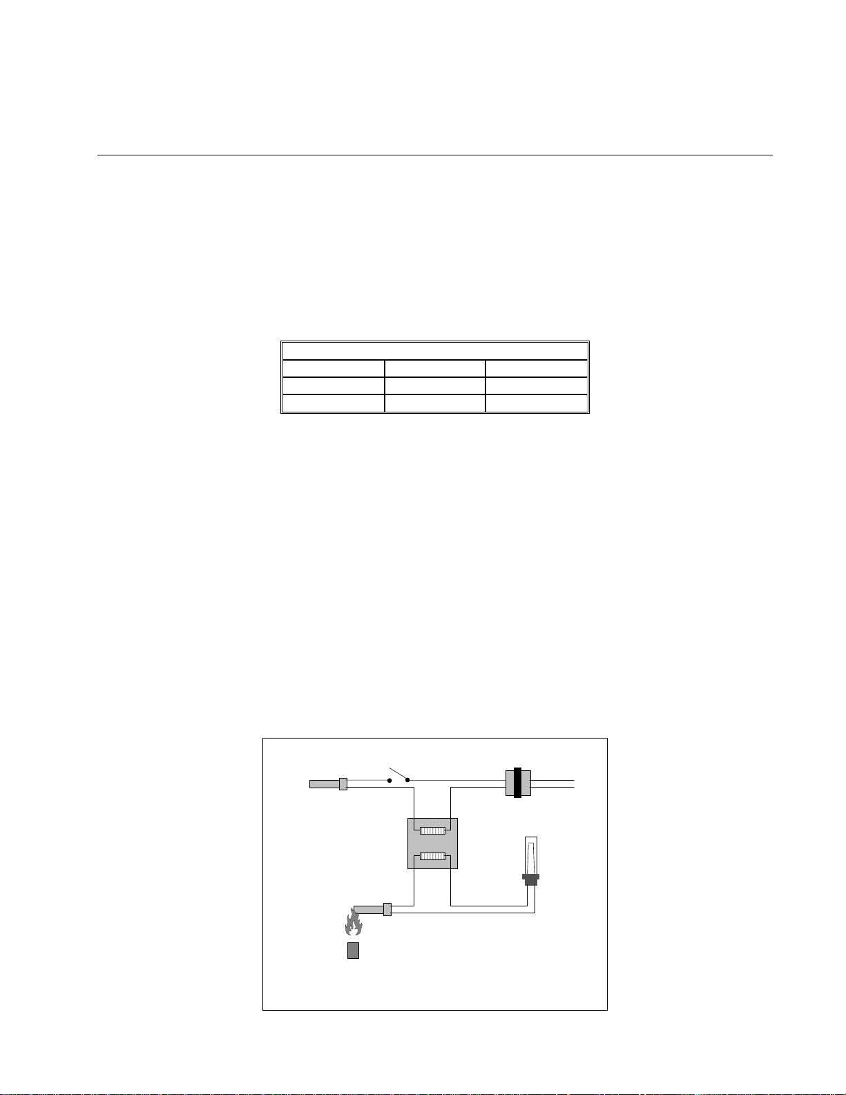
PILOT IGNITION SYSTEM
The pilot ignition system is comprised of the pilot orifice, pilot hood, and a thermopile. The pilot
serves two purposes. The first is to light the burner, the second is to heat the thermopile. In operation, the thermopile is in contact with the pilot flame and generates millivolts. The millivolt output
passes through a normally closed high-limit switch and energizes the gas valve pilot coil, which in
turn opens the pilot valve. If the pilot flame is extinguished, voltage is lost to the gas valve pilot coil
and the pilot valve closes. A separate 24-volt circuit, activated by the fryer ON/OFF switch, provides voltage through the thermostat or controller to the gas valve main coil, which opens the main
valve. The gas valve is constructed so that the main valve will not open if the pilot valve is not
open. The pilot flame must be manually lit (either with a match or with an optional built-in piezo
igniter) when the fryer is first placed into operation.
ON/OFF
Controlling Thermostat
or
Controller
Switch
Main Coil
24 VAC
Transformer
Line Voltage
Line Voltage
Gas Valve
Pilot Coil
Thermopile
Pilot
The Pilot System
1-1
High-Limit
Thermostat
Page 8
CONTROL OPTIONS
45 Series fryers may be equipped with thermostat controllers, analog controllers, digital controllers,
basket lift timers, or Computer Magic computers.
In fryers equipped with thermostat controls, the fryer and melt cycle are turned on and off by means
of rocker switches and the temperature is set by means of a knob connected directly to the frypotmounted thermostat. These units have no interface board. In this type of unit, when the melt cycle
switch is placed in the ON position, the fryer stays in the melt cycle mode until the switch is manually placed in the OFF position, even if the frypot is at setpoint temperature.
Fryers equipped with other types of controllers have an interface board located in the component
shield behind the control panel.
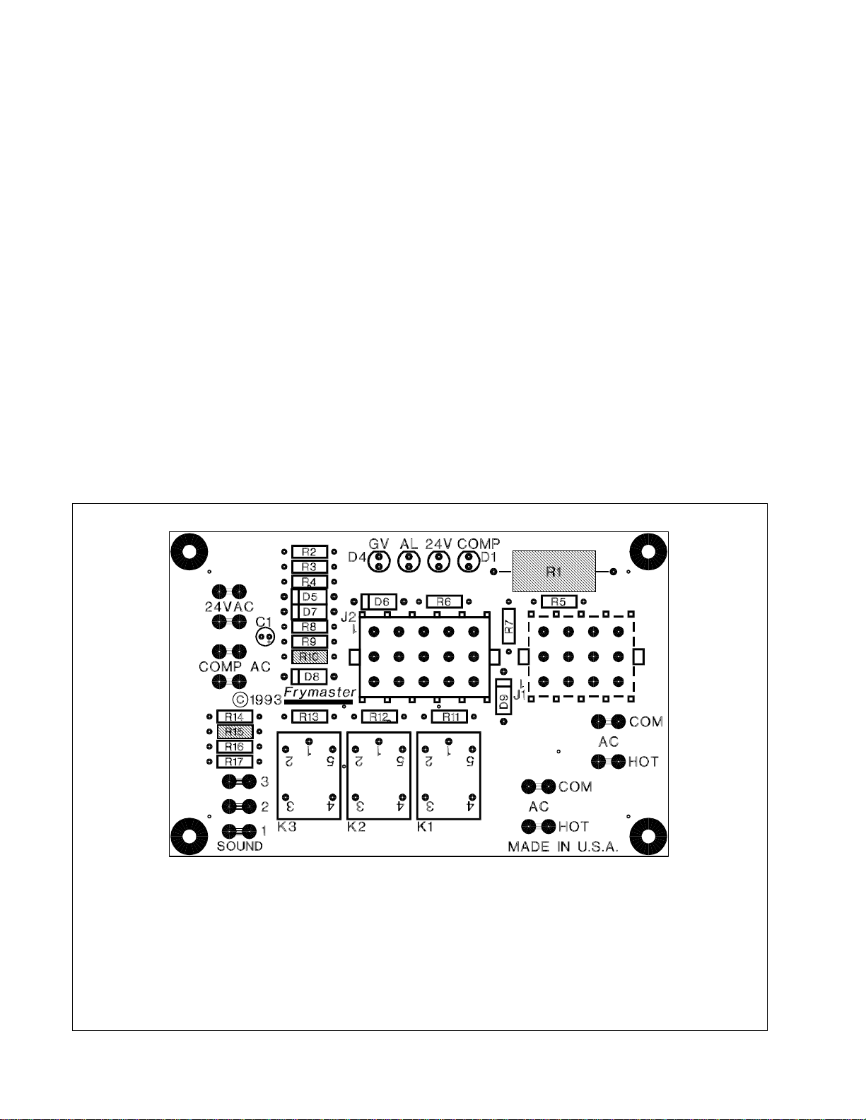
INTERFACE BOARDS
The interface board provides the link between the controller/computer and the fryer’s individual
components without requiring excessive wiring, and allows the controller to execute commands
from one central point. When built, depending upon the configuration of the particular fryer, any
one of three different boards may be used. Regardless of the particular board installed when the
fryer was built, P/N 806-3548 is the universal replacement part.
1
4
7
10
13
2
5
8
11
14
3
6
9
NOTES:
1. RELAYS K1 AND K2 ARE FOR BELL CRANK BASKET LIFTS. THEY ARE NOT PRESENT ON
BOARDS 806-5490 (U.S. AND NON-CE EXPORT UNITS W/O BASKET LIFTS) OR 806-7501
(CE UNITS, WITH OR WITHOUT BASKET LIFTS).
2. RESISTORS R1, R10, AND R15 ARE NOT USED ON ANY OF THE THREE BOARDS.
3. RESISTORS R11 AND R12 ARE NOT USED ON 806-5490 BOARDS.
15
12
3
6
9
12
2
5
8
11
4
1
7
10
INTERFACE BOARDS 806-3548, 806-5490, AND 806-7505
1-2
Page 9
r
FREQUENTLY USED TEST POINTS FOR 45 SERIES INTERFACE BOARDS
Mete
Test
12 VAC Power to Controller 50 VAC Scale 1 and 3 of J2 12-18
24 VAC Power 50 VAC Scale 24 VAC Terminals 22-28
24 VAC Power to Gas Valve 50 VAC Scale 6 on J1 and GROUND 22-28
120 VAC Power 250 VAC Scale 7 and 12 of J1 110-125
Probe Resistance* R x 1000 OHMS 2 and 3 of J1 **
** Disconnect 15-Pin harness from controller before testing probe circuit.
** See Probe Resistance Chart at end of chapter.
Setting
Pins Results
Four LEDs, arranged across the top of the boards and identified in the table below, are provided to
assist in troubleshooting.
45 SERIES INTERFACE BOARD
LED DIAGNOSTIC LIGHTS
Indica tes 24 VAC to the gas va lve
GV
AL Indicates open Drain Safety Switch (if installed)
24V Ind ic ates 2 4 VAC from tr ansfo r mer
Indica tes 12 VAC to c omputer
COMP
Every board contains one heat relay (K3), and may contain two basket lift relays (K1 and K2). As
shipped from the factory, fryers with bell crank basket lifts will have relays K1, K2, and K3. All
other factory-original fryers will have boards with only relay K3.
THERMOSTATS AND TEMPERATURE PROBES
Different types of thermostats are used in 45 Series fryers, depending on the fryers’ configuration.
Fryers equipped with Thermostat Controls have an adjustable controlling (operating) thermostat.
The temperature at which the thermostat opens and closes is adjusted by physically changing the setting of the thermostat itself by means of an attached knob. When new, the Fenwal controlling thermostat used in 45 Series fryers is sensitive to one-degree changes in temperature.
CAUTION
Fenwal thermostats are used in a number of Frymaster products. The thermostat for
the 45 Series is 4 inches long. Do not use 3-inch Fenwal thermostats in 45 Series
fryers.
Fryers equipped with all other type controls have a temperature probe. In these units, the probe
resistance varies directly with the temperature. That is, as the temperature rises, so does resistance
at a rate of approximately 2 ohms for every 1º (F or C). Circuitry in the controller monitors the probe
resistance and controls burner firing when the resistance exceeds or falls below programmed
temperatures (setpoints). The temperatures are programmed by means of a keypad on the face of the
controller.
All 45 Series fryers are equipped with a high-limit thermostat. In the event that the fryer fails to
properly control the oil temperature, the high-limit thermostat prevents the fryer from overheating to
the flash point. The high-limit thermostat acts as a normally closed power switch that opens when
1-3
Page 10
exposed to temperatures in the range of 425ºF to 450ºF (218ºC to 232ºC). The high-limit thermostat
is the same for CE and Non-CE applications, but the terminals for attaching it to Robertshaw and
Honeywell gas valves differ. When a replacement high-limit thermostat is ordered, make sure the
kit appropriate for the valve in use is ordered.
1.2 Accessing Fryers for Servicing
DANGER
Moving a fryer filled with cooking oil/shortening may cause spilling or splattering of
the hot liquid. Follow the draining instructions in Chapter 4 of the 45 Series Gas
Fryer Installation and Operation Manual before attempting to relocate a fryer for
servicing.
1. Shut off the gas supply to the unit. Unplug the power cord(s). Disconnect the unit from the gas
supply.
2. Remove any attached restraining devices.
3. Relocate the fryer for service accessibility.
4. After servicing is complete, reconnect the unit to the gas supply, reattach restraining devices,
and plug in the electrical cords.
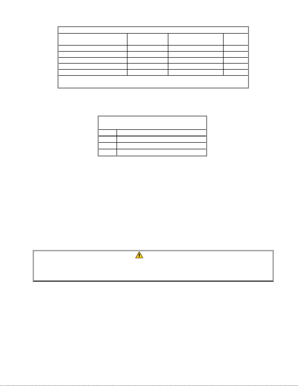
1.3 Checking the Burner Manifold Gas Pressure
WARNING
This task should be performed by qualified service personnel only.
1. Ensure that the gas valve knob or button is in the OFF position.
2. Remove the pressure tap plug from the end of the manifold (see illustration below for location)
and connect a gas pressure-measuring device to the port.
Remove this plug and connect a gas
pressure-measuring device t o the port.
3. Place the gas valve in the ON position then place the fryer power switch in the ON position.
When the burner lights and continues to burn, compare the pressure reading to that for the corresponding gas in the tables on the following page.
1-4
Page 11
CE Standard
Burner Manifold Gas Pressures
Pressure
(mbar)
7,5
10
10
20,6
Non-CE Standard
Burner Manifold Gas Pressures
Gas Pressure
Natural
Propane
3.5" W.C.
0.73 kPa
8.25" W.C.
2.05 kPa
Gas
Natural Gas Lacq
(G20) under 20 mbar
Natural Gas Gronique
(G25) under 25 mbar
Natural Gas Gronique
(G20) under 20 mbar
Propane
(G31) under 37 or 50 mbar
* Belgian G25 = 7,0 mbar
*
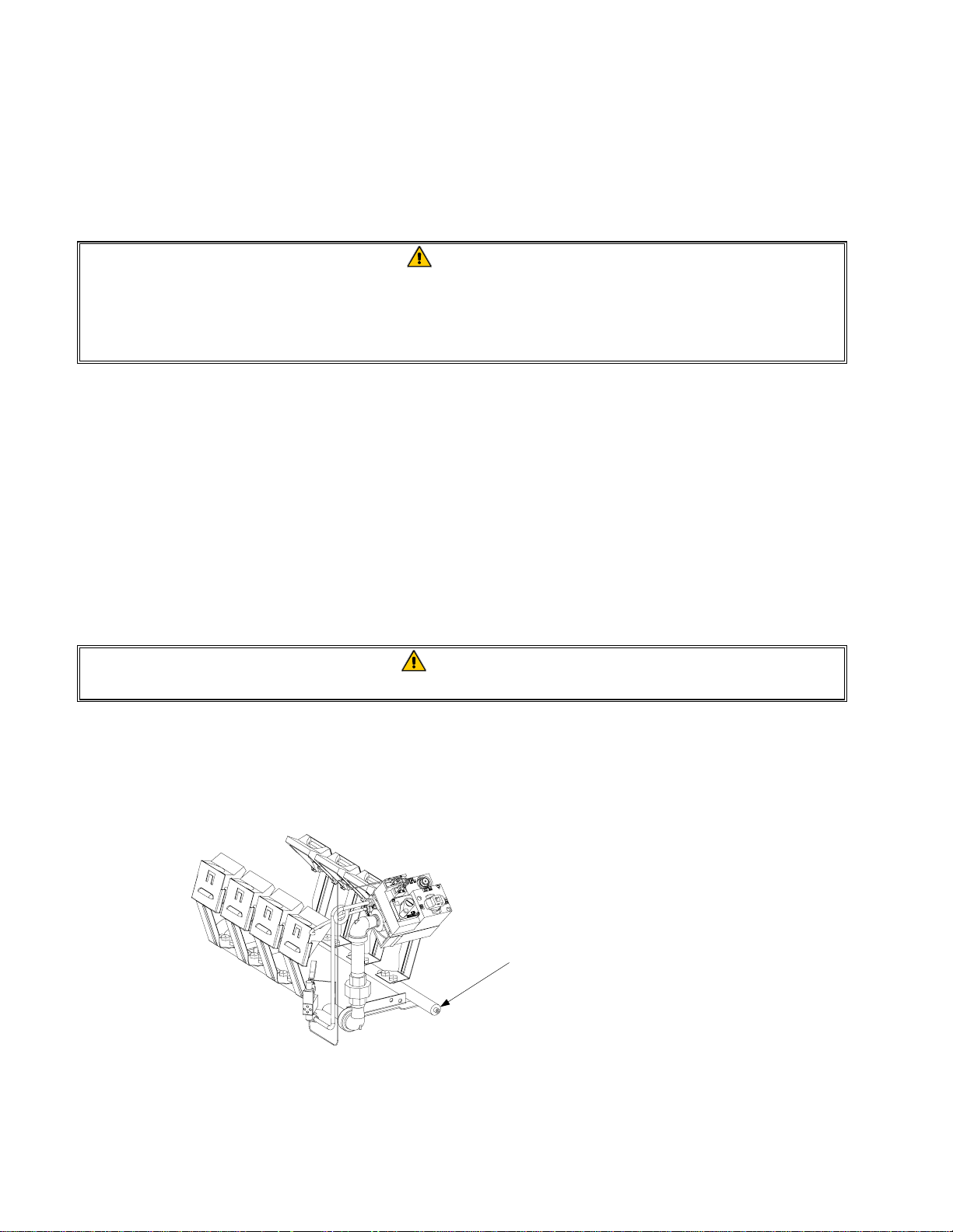
4. If the measured gas pressure does not match the appropriate pressure in the tables above, remove
the cap from the gas valve regulator and adjust to the correct pressure.
Robertshaw Valve
(Non-CE Units)
Honeywell Valve
(Non-CE Units)
Regulator Adjustment Screw Cap
Honeywell Valve
(CE Units)
5. Place the fryer power switch and the gas valve in the OFF position. Remove the fitting from the
pressure tap hole and reinstall the plug. Place the gas valve in the ON position, and check for and
eliminate any gas leaks. Place the gas valve in the OFF position.
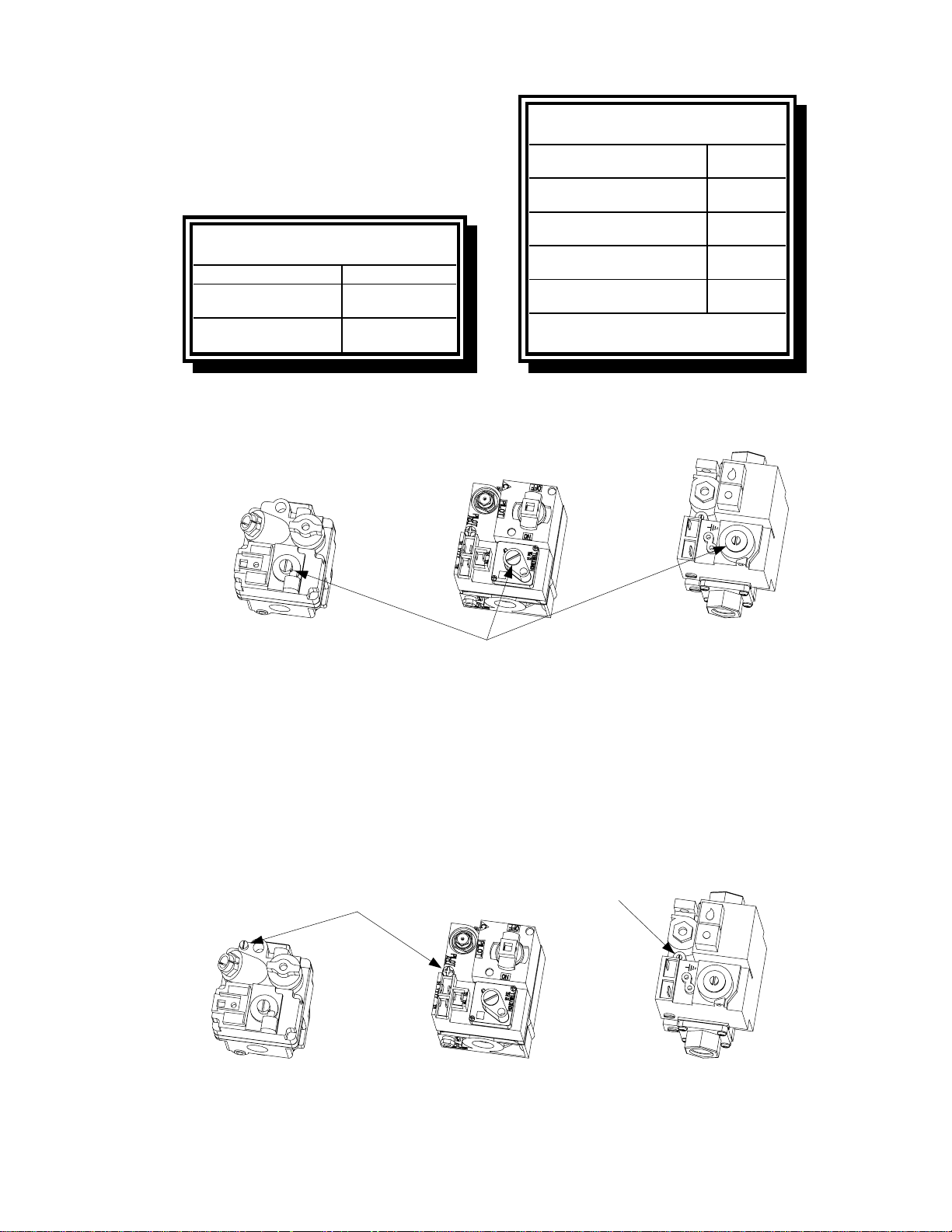
1.4 Adjusting the Pilot Flame
1. On non-CE valves, remove the cap covering the pilot adjustment screw. On all valves, turn the
pilot adjustment screw counterclockwise to increase the length of the flame or clockwise to decrease the length of the flame. Adjust the flame to a length of 1 to 1½ inches (25 to 38mm).
To access the pilot adjustment screw on
Non-CE valves, this cap must be removed.
Pilot Adjustment Screw
Robertshaw Valve
(Non-CE Units)
Honeywell Valve
(Non-CE Units)
2. On Non-CE valves, reinstall the pilot adjustment screw cap.
1-5
Honeywell Valve
(CE Units)
Page 12
1.5 Cleaning the Gas Valve Vent Tube
1. Carefully unscrew the vent tube from the gas valve. NOTE: The vent tube may be straightened
for ease in removal.
2. Pass a piece of ordinary binding wire (.052 inch diameter) or equivalent through the tube to re-
move any obstruction.
3. Remove the wire, then blow through the tube to ensure it is clear.
4. Reinstall tube and bend it so that the opening is pointing downward.
1.6 Adjusting Burner Ceramic Target Spacing and Alignment
DANGER
Drain the frypot or remove the handle from the drain valve before proceeding further.
Proper spacing of the top edge of the burner ceramic targets is ¾ inch (13 mm) from the frypot side.
To adjust target spacing, bend the brackets to which they are attached away or toward the frypot to
the proper distance. (A length of board of the proper thickness is useful as a gauge to verify spacing
and alignment.)
1.7 Calibrating the Thermostat Control
NOTE: The fryer control panel must be hinged down from the control panel mounting frame to per-
form thermostat calibration. In order to hinge the control panel down, the thermostat knob must be
removed from its shaft. It is secured with a setscrew located opposite the index mark on the knob.
1. Fill the frypot to the lower OIL-LEVEL line with cooking oil/shortening. If solid shortening is
used, it must be pre-melted before starting the calibration procedure.
2. Ensure the fryer ON/OFF Switch is in the OFF position, then light the pilot. (Refer to Chapter 3
of the 45 Series Gas Fryer Installation and Operation Manual for detailed lighting instructions.)
3. Insert a good grade thermometer or pyrometer into the frypot so that it touches the thermostat
guard.
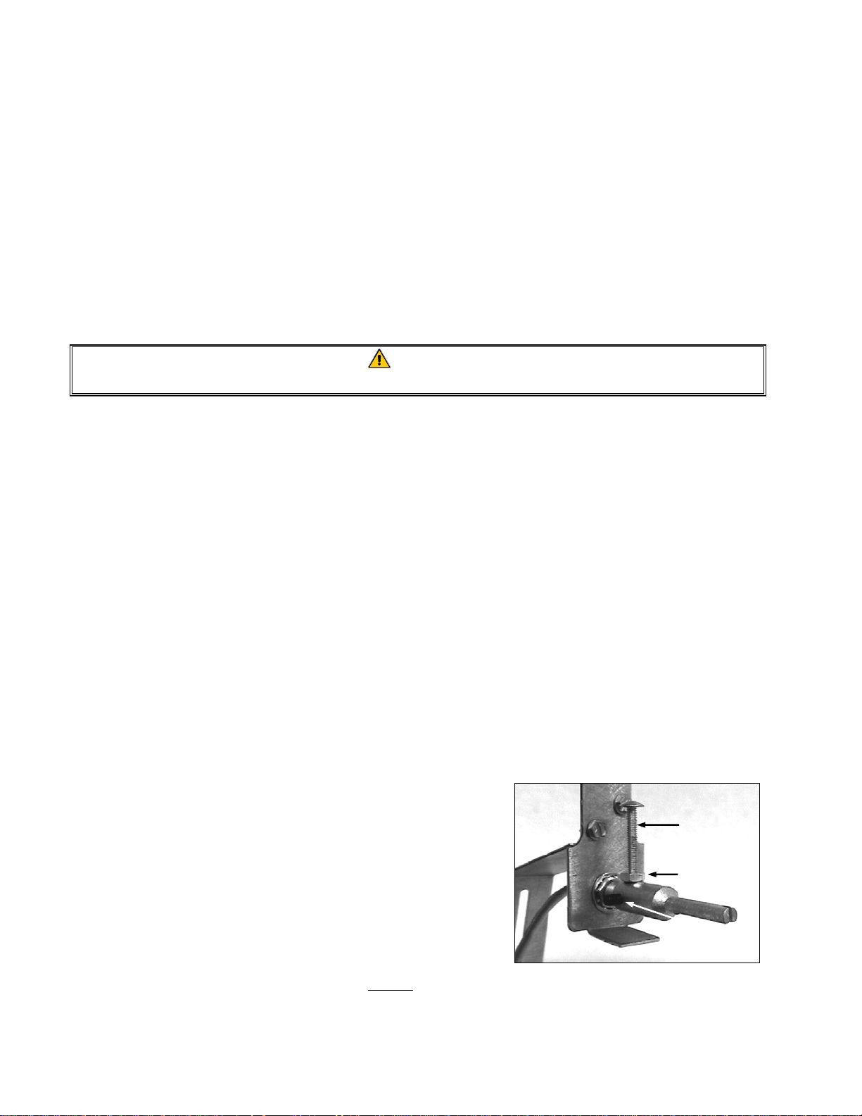
4. Loosen the setscrew and stop screw securing the ther-
mostat shaft extension to the flexible shaft. Remove
the extension to expose the slot in the end of the flexible shaft.
5. Place the fryer ON/OFF switch in the ON position.
NOTE: If the burner does not light at this time, it
Stop screw
Locking nut
Setscrew
does not mean the thermostat is defective!
Use a small flat-tipped screwdriver to slowly turn the flexible shaft counterclockwise until the
burner lights. Turning the shaft counterclockwise causes the burner to light and clockwise
causes it to shut off.
1-6
Page 13
6. When the cooking oil/shortening temperature reaches 325ºF (162ºC), turn the flexible shaft
slowly clockwise until the burner shuts off.
7. Allow the fryer to sit for a few minutes, then slowly turn the flexible shaft counterclockwise un-
til the burner lights.
8. Repeat steps 6 and 7 at least three times to ensure an accurate setting is obtained. The Thermo-
stat Control is considered to be properly calibrated when the burner lights as the cooking
oil/shortening cools to 325ºF (162ºC)—not when the burner shuts off as the temperature rises.
9. Once the calibration point of 325ºF (162ºC) is determined, allow the burner to cycle on and off at
least 3 times to be sure it will light at the calibrated temperature.
10. After the calibration is complete, place the fryer power switch in the OFF position and disconnect the fryer from the electrical supply.
11. Carefully replace the thermostat shaft extension, ensuring that the stop screw is pointed straight
up. Tighten the stop screw and locking nut and the setscrew, being careful not to rotate the flexible shaft.
CAUTION
The thermostat flexible shaft must not be rotated while installing the thermostat
shaft extension!
When handling the thermostat, do not rotate the shaft more than two turns in either
direction. Doing so will cause damage to the thermostat.
12. Close the fryer control panel and replace the screws the upper corners.
13. Reinstall the thermostat knob with its pointer aligned with the 325ºF (162ºC) index mark on the
temperature dial.
14. Reconnect the fryer to the electrical supply.
1.8 Replacing Fryer Components
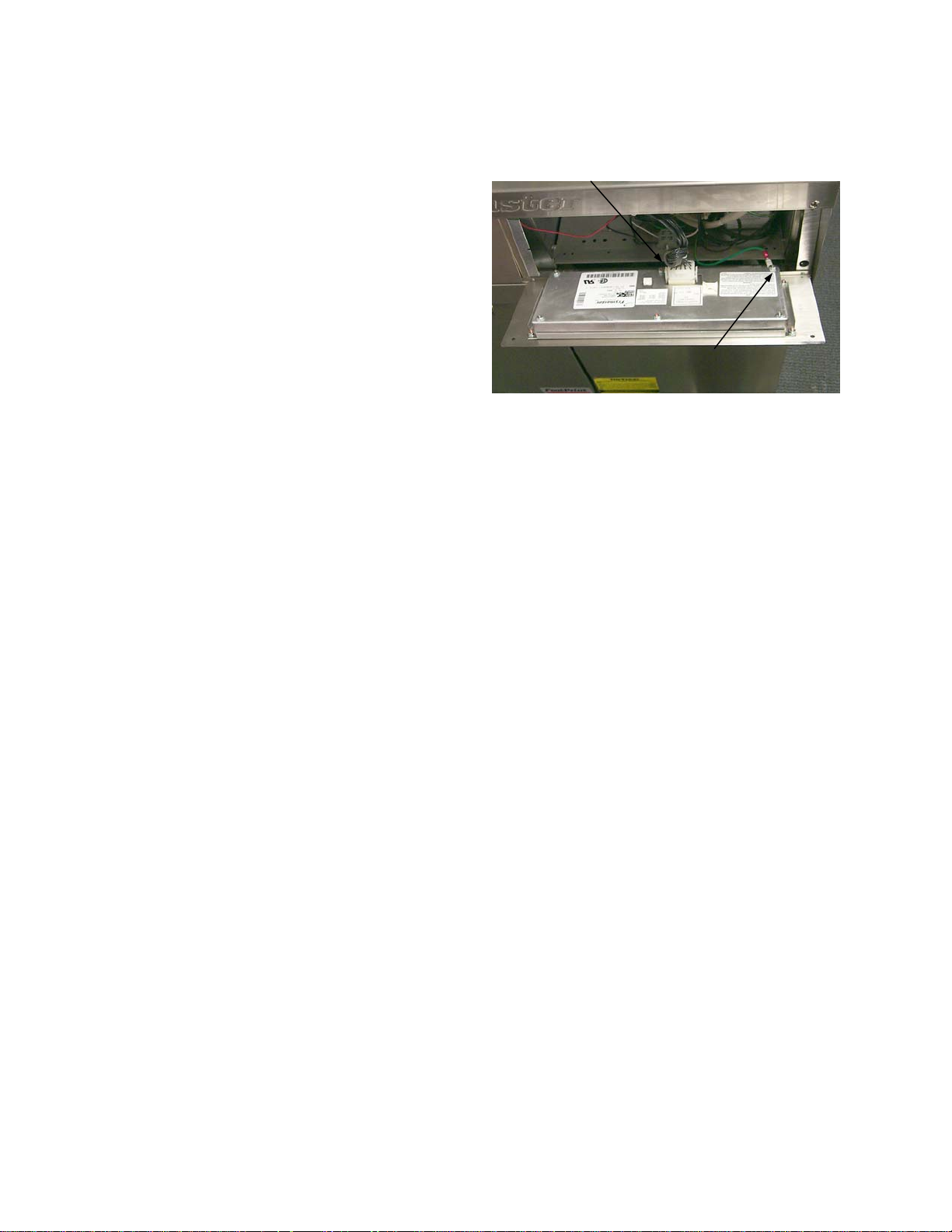
1.8.1 Replacing the Controller or Computer
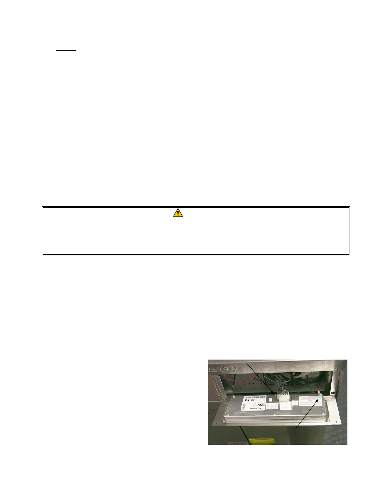
Unplug
harness
1. Disconnect the fryer from the electrical power
supply.
2. Unscrew the two control panel screws. The
control panel is hinged at the bottom and will
swing open from the top.
3. Unplug the fryer wiring harness from the back
of the controller/computer and disconnect the
grounding wire.
Disconnect
grounding wire
1-7
Page 14
4. Remove the controller/computer by lifting it from the hinge slots in the fryer control panel
frame.
5. Reverse the procedure to install a new controller/computer.
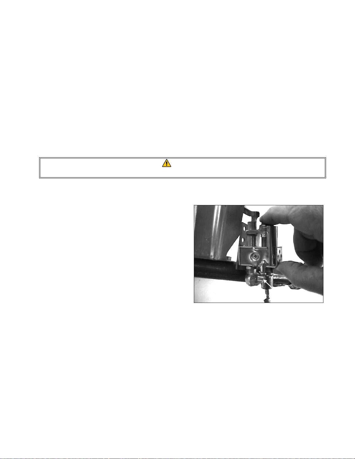
1.8.2 Replacing the Operating Thermostat
CAUTION
The thermostat must be calibrated after installation is complete. Refer to Section 1.7
for calibration instructions.
When handling the thermostat, do not rotate the shaft more than two turns in either
direction. Doing so will cause damage to the thermostat.
1. Disconnect the fryer from the electrical supply and drain the frypot.
2. Loosen the setscrew securing the thermostat knob and remove the knob. Remove the screws
from the upper left and right corners of the control panel. The control panel is hinged at the bottom and will swing open from the top.
3. Disconnect the 9-Pin connector and remove the control panel from the fryer by disengaging its
tabs from the hinge slots in the mounting frame.
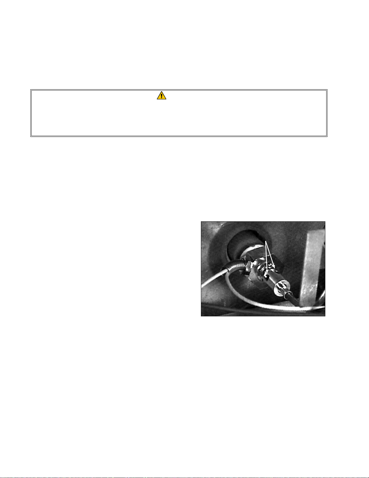
4. Loosen the setscrews securing the flexible shaft
to the thermostat shaft and slip the flexible shaft
Loosen these setscrews and slip the
flexible shaft off the thermostat shaft.
off the thermostat shaft.
5. Remove the flexible shaft guide by removing
the two sheet metal screws securing it to the upper frame.
6. Disconnect the thermostat leads from Pin 14 in
the 20-pin terminal block and from the gas
valve terminal.
NOTE: If the fryer is configured with a melt cycle, the thermostat leads will be connected to the
melt cycle timer motor or PC board rather than to the terminal block and gas valve. Disconnect
the leads from the motor or PC board if this is the case.
7. Unscrew the thermostat from the frypot and remove.
8. Apply Loctite™ PST56765 thread sealant or equivalent to the replacement thermostat threads.
9. Reverse steps 1 through 7 to install the replacement.
1.8.3 Replacing the Temperature Probe
1. Disconnect the fryer from the electrical supply.
1-8
Page 15
2. Drain the frypot.
3. Remove the screws from the upper left and
right corners of the control panel. The panel
Unplug
harness
is hinged at the bottom and will swing open
from the top.
4. Unplug the wiring harness from the back of
the controller and disconnect the grounding
wire.
5. Remove the controller from the fryer by lift-
ing it from the hinge slots in the control panel
Disconnect
grounding wire
frame.
6. Remove the two screws from the base of the interface board mounting bracket.
7. Disconnect the 12-pin plug from the back of the interface board and lay the board in the left end
of the compartment with all other wires still connected.
8. Remove the 12-volt transformer from the component shield and lay it in the left end of the com-
partment with wires still connected.
9. Using a pin-pusher, remove the temperature probe wires (pins 1 and 2) from the 12-pin plug dis-
connected in step 7.
10. Unscrew the temperature probe from the frypot and remove.
11. Apply Loctite™ PST56765 thread sealant or equivalent to new probe threads.
12. Reverse steps 1 through 10 to install the replacement probe.
1.8.4 Replacing the High-Limit Thermostat in Fryers with Thermostat Controls
1. Disconnect the fryer from the electrical supply.
2. Drain the frypot.
3. Loosen the setscrew securing the thermostat knob and remove the knob. Remove the screws
from the upper left and right corners of the control panel. The control panel is hinged at the bottom and will swing open from the top.
4. Disconnect the 9-Pin connector and remove the control panel from the fryer by disengaging its
tabs from the hinge slots in the mounting frame.
6. Disconnect the high-limit thermostat leads from the gas valve pilot coil.
7. Unscrew the high-limit thermostat from the frypot and remove.
8. Apply Loctite™ PST56765 thread sealant or equivalent to the replacement thermostat threads.
9. Reverse steps 1 through 7 to install the replacement.
1-9
Page 16
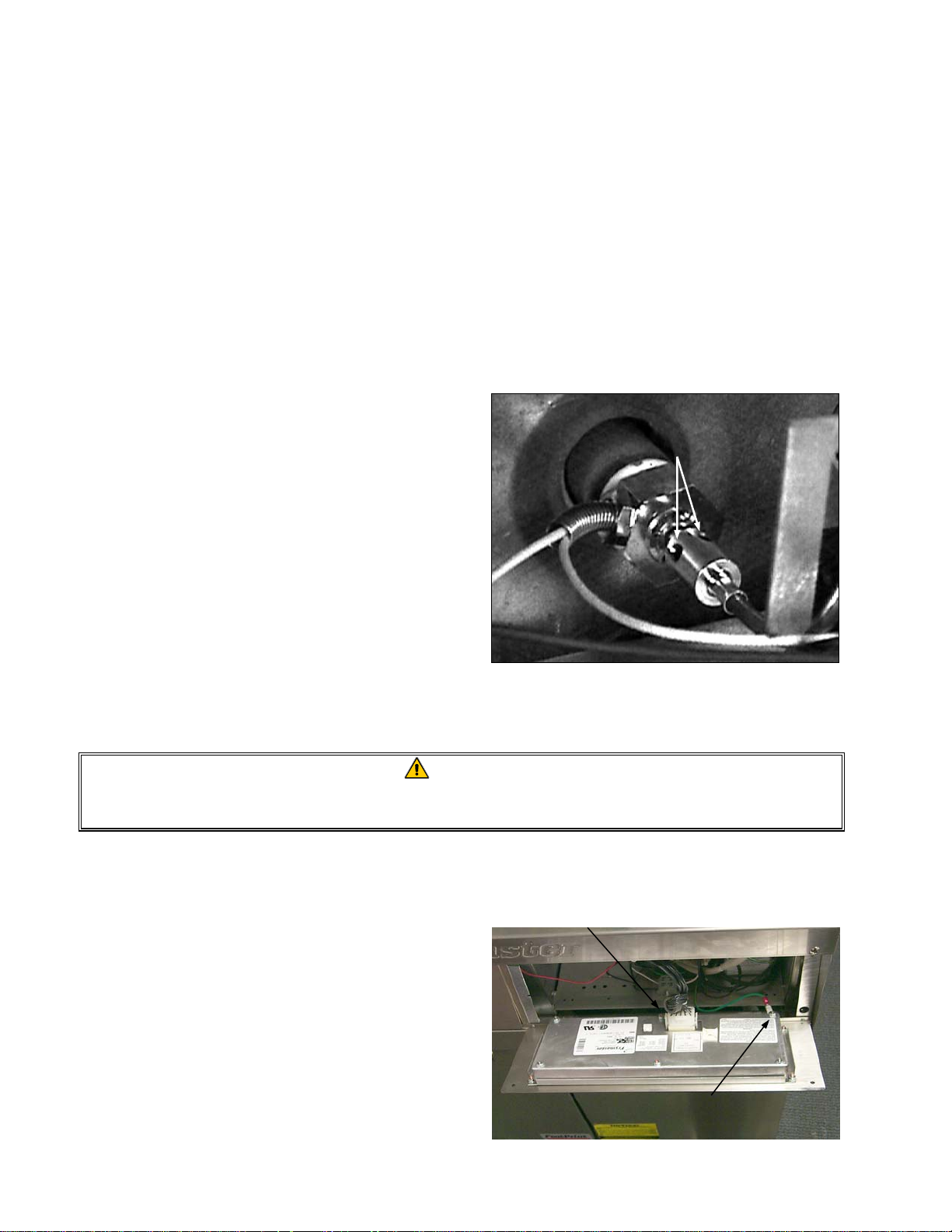
1.8.5 Replacing the High-Limit Thermostat in Fryers with Other Than Thermostat
Controls
1. Disconnect the fryer from the electrical power
supply.
Unplug
harness
2. Drain the frypot.
3. Remove the screws from the upper left and
right corners of the controller panel. The controller is hinged at the bottom and will swing
open from the top.
4. Unplug the wiring harness and disconnect the
grounding wire from the the controller.
Disconnect
grounding wire
5. Remove the controller from the fryer by lifting it from the hinge slots in the fryer control panel
frame.
6. Remove the two screws from the base of the interface board mounting bracket.
7. Disconnect the 12-pin plug from the back of the interface board and lay the board in the right
end of the compartment with all other wires still connected.
8. Remove the 12-volt transformer and lay it in the right end of the compartment with wires still
connected.
9. Remove the high-limit thermostat wires from the gas valve pilot coil and pull them up through
the control shield.
10. Unscrew the high-limit thermostat from the frypot and remove.
11. Apply Loctite™ PST56765 thread sealant or equivalent to the replacement thermostat’s threads
and screw it into the frypot.
12. Attach the appropriate terminals (furnished in the replacement thermostat kit) to the thermostat
leads.
13. Reverse steps 1 through 9 to complete installation of the replacement thermostat.
1.8.6 Replacing the Heat Mode Indicator Light in Fryers with Thermostat Controls
1. Disconnect the fryer from the electrical supply.
2. Loosen the setscrew securing the thermostat knob and remove the knob. Remove the screws
from the upper left and right corners of the control panel. The control panel is hinged at the bottom and will swing open from the top.
1-10
Page 17

3. Disconnect the 9-pin connector and remove the control panel from the fryer by disengaging its
tabs from the hinge slots in the mounting frame.
4. Carefully press the light out from the back of the control panel. Disconnect one wire at a time
and reconnect it to the replacement light until all wires are transferred.
5. Carefully press the light back into the control panel.
6. Reverse steps 1-3 to reassemble the fryer.
1.8.7 Replacing the Power or Melt Cycle Switch in Fryers with Thermostat Controls
1. Disconnect the fryer from the electrical supply.
2. Loosen the setscrew securing the thermostat knob and remove the knob. Remove the screws
from the upper left and right corners of the control panel. The control panel is hinged at the bottom and will swing open from the top.
3. Disconnect the 9-pin connector and remove the control panel from the fryer by disengaging its
tabs from the hinge slots in the mounting frame.
4. Using a flat-tipped screwdriver, disconnect the chrome bezel from the tabs on the switch and
press the switch out from the front.
5. Carefully press the new switch back into the chrome bezel, making sure the tabs on the switch
engage the slots in the bezel.
6. Disconnect one wire at a time from the old switch and reconnect it to the new switch until all
wires have been transferred.
7. Reverse steps 1-3 to reassemble the fryer.
1.8.8 Replacing the Melt Cycle Timer in Fryers with Thermostat Controls
NOTE: In early 1999, PC board melt cycle timers replaced melt cycle timer motors in new fryers.
1. Disconnect the fryer from the electrical supply.
2. Loosen the setscrew securing the thermostat knob and remove the knob. Remove the screws
from the upper left and right corners of the control panel. The control panel is hinged at the bottom and will swing open from the top.
3. Remove the screws securing the timer motor (or the PC board timer bracket) to the fryer (see il-
lustration on Page 2-16).
4. Remove one wire at a time and reconnect it to the replacement PC board timer until all wires
have been transferred.
5. Reverse steps 1-3 to reassemble the fryer.
1-11
Page 18
1.8.9 Replacing Burner Ceramic Targets
DANGER
Drain the frypot or remove the handle from the drain valve before proceeding further.
1. Disconnect fryer from electrical and gas supplies.
2. On FM45 fryers, remove square-drain sections as necessary to expose burner.
3. Disconnect the wires from the gas valve terminal block, marking each wire to facilitate recon-
nections.
4. Remove the high-limit thermostat wires from the gas valve pilot coil.
5. Disconnect the pipe union collar at the right side of the gas valve.
6. Remove the burner heat shield hanger screws at the front of the burner and remove the heat
shield.
7. Remove the burner hanger screws and lower the front of the main burner. Pull it forward to
clear the rear burner hanger, then lower the burner to the floor.
8. Raise the front of the fryer enough to slide the burner from under the fryer cabinet.
9. To replace only the ceramic targets, straighten the target locking tabs with a pair of needle nose
pliers or a screwdriver, and slide the target up and off the bracket. Slide the replacement target
onto the bracket and bend the locking tabs down.
To replace the entire target assembly, use a ½-inch (13mm) box end wrench to remove the two
brass orifices that hold the assembly to the burner manifold. Position the new assembly and replace the orifices.
WARNING
Use extreme care to prevent cross-threading and stripping when reinstalling the
brass orifices.
10. Reverse steps 1-8 to reinstall the burner assembly. Check spacing and alignment of targets in
accordance with Section 1.5.
1.8.10 Replacing the Gas Valve
DANGER
Drain the frypot or remove the handle from the drain valve before proceeding further.
1. Disconnect fryer from electrical and gas supplies
1-12
Page 19
p
2. Disconnect the wires from the gas valve terminal block, marking each wire to facilitate recon-
nections.
3. Remove the high-limit thermostat wire from the gas valve pilot coil.
4. Disconnect the pilot gas line fitting from the gas valve.
5. Disconnect the pipe union collars to the left and right of the gas valve and remove the valve.
6. Remove the pipe fittings from the old gas valve and install on the replacement valve, using Loc-
tite™ PST56765 or equivalent pipe thread sealant on threads.
7. Reverse steps 1-5 to install the replacement gas valve.
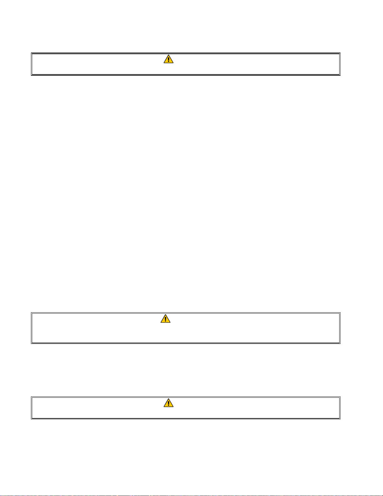
1.8.11 Replacing the Pilot Assembly or Thermopile
DANGER
Drain the frypot or remove the handle from the drain valve before proceeding further.
1. Remove the burner assembly in accordance with steps 1-8 of Section 1.8.9.
2. To replace only the thermopile:
a. Bend the clip at the bottom of the pilot as-
sembly and press the thermopile out of the
pilot assembly from the top.
b. Disconnect the thermopile fitting from the
gas valve pilot coil.
c. Reverse steps a and b to install the re-
placement thermopile.
Bend clip to release
thermo
ile.
3. To replace the complete pilot assembly:
a. Disconnect the pilot tubing from the bottom of the pilot assembly.
b. Remove the screw from the pilot mounting bracket to release the pilot assembly.
c. Disconnect the thermopile fitting from the gas valve pilot coil.
d. Reverse steps a through c to install the replacement pilot assembly.
4. Reinstall the burner assembly by reversing steps 1-8 of Section 1.8.9.
1-13
Page 20
1.8.12 Replacing the Frypot
1. Drain the frypot.
2. Remove all accessories (e.g., frypot covers, basket lift arms, etc.) from the fryer.
3. Disconnect the fryer from gas and electrical supplies.
4. Remove the screws from the top cap above the control panel and lift it up and off the fryer(s).
5. If the fryer is equipped with other than a thermostat control, skip to Step 10.
6. Loosen the setscrew securing the thermostat knob to the thermostat flexible shaft and remove the
knob. Remove the screws from the upper left and right corners of the control panel. Disconnect
the 9-pin connector and remove the control panel from the fryer.
7. Loosen the setscrews securing the flexible
shaft to the thermostat shaft and slip the flexible shaft off the thermostat shaft.
Loosen these setscrews and slip
flexible shaft off the thermostat shaft.
8. Remove the flexible shaft bracket from the
fryer by removing the two sheet metal screws
securing it to the upper frame.
9. Disconnect the thermostat leads from Pin 14
in the 20-pin terminal block and from the gas
valve terminal. Mark each wire to facilitate
reconnection. Skip to Step 14.
NOTE: If the fryer is configured with a melt cycle, the thermostat leads will be connected to
the melt cycle timer motor rather than to the terminal block and gas valve. Disconnect the leads
from the motor if this is the case.
CAUTION
When handling the thermostat, do not rotate the shaft more than two turns in either
direction. Doing so will cause damage to the thermostat.
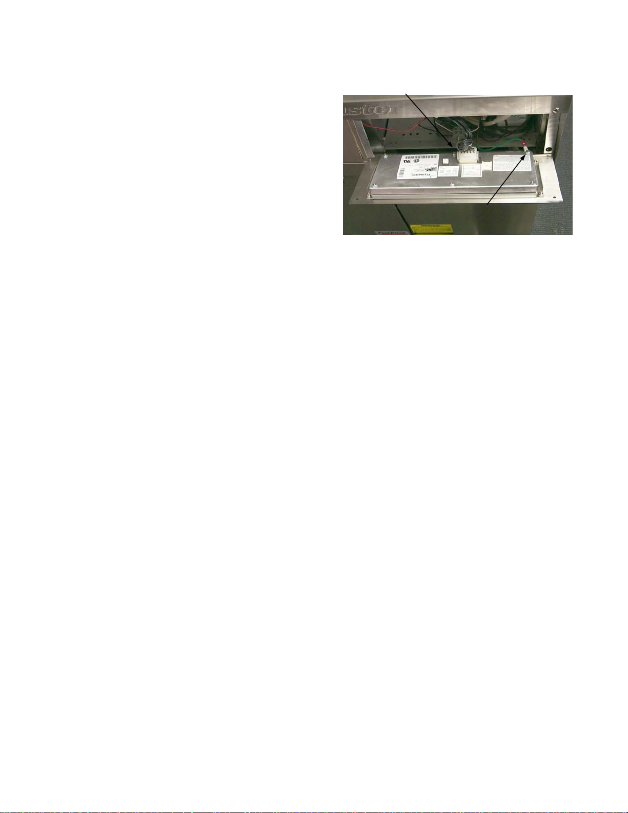
10. For fryers equipped with other than Thermostat Controls, remove the screws from the upper left and right corners of the control panel.
Unplug the wiring harness from the back of
move the temperature probe leads (pins 1
and
Unplug
harness
the controller and disconnect the grounding
wire. Remove it from the fryer by lifting it
from the hinge slots in the fryer control frame.
11. Remove the two screws from the base of the
interface board bracket.
12. Disconnect the 12-pin plug from the back of
the interface board. Use a pin pusher to re-
1-14
Disconnect
grounding wire
Page 21
2) and the high-limit thermostat leads (pins 6 and 8) from the plug. Leave all other wires con-
nected. Leave the interface board lying on the shield.
13. Remove the louvered frame above the control panel opening.
14. Remove the screws securing the component shield to the fryer.
15. Disconnect the wires from components in component shield and mark to facilitate reconnection.
16. Disconnect the wires from the gas valve terminal block. Mark each wire to facilitate reconnec-
tion.
17. Remove the cover from the safety drain switch, disconnect the wires from the switch, and pull
them out of the switch box.
18. Pull up and forward on the component shield to clear the rear mounting stud on the front of the
frypot and remove it from the fryer by rotating its right side up and to the left.
19. Disconnect the pipe union on the right side of the gas valve.
20. On FM45 fryers, remove the section of square drain from the drain valve of the frypot to be re-
moved.
21. Remove the frypot hold down bracket.
22. Remove the screws from the flue cap sides and back and lift it clear of the fryer(s).
23. Remove the oil return line from the front of the frypot to be removed.
24. Lift the complete frypot assembly (frypot, burner, gas valve, and flue) from the fryer cabinet.
25. Transfer the burner heat shield and burner to the replacement frypot.
26. Remove the drain valve, thermostat or temperature probe, and high-limit thermostat and install
on replacement frypot.
CAUTION
Before installing the thermostat/temperature probe, high-limit thermostat, and drain valve
on the replacement frypot, clean their threads and apply Loctite™ PST56765 thread
sealant or equivalent to the threads.
27. Reverse steps 1-25 to reassemble the fryer.
1.9 Troubleshooting and Problem Isolation
Because it is not feasible to attempt to include in this manual every conceivable problem or trouble
condition that might be encountered, this section is intended to provide technicians with a general
knowledge of the broad problem categories associated with this equipment, and the probable causes
of each. With this knowledge, the technician should be able to isolate and correct any problem encountered.
1-15
Page 22

Problems you are likely to encounter can be grouped into seven broad categories:
1. Ignition failures
2. Improper burner functioning
3. Improper temperature control
5. Filtration problems
6. Leakage problems
7. Basket lift malfunctions
4. Computer-related problems
The probable causes of each category are discussed in the following sections. A series of Troubleshooting Guides (decision trees) is also included at the end of the chapter to assist in identifying
some of the more common problems.
1.9.1 Ignition Failures
Ignition failures occur when the 24VAC power supply to the gas valve is interrupted, when the gas
supply is interrupted, or when the pilot flame is extinguished.
Solid-state controllers indicate ignition failure by illuminating the heat light and trouble light simultaneously. All other controllers give no specific indication of an ignition failure.
There are three primary reasons for ignition failure, listed in order of probability:
1. Problems related to the gas and/or electrical power supplies.
2. Problems related to the electronic circuits.
3. Problems related to the gas valve.
PROBLEMS RELATED TO THE GAS AND/OR ELECTRICAL POWER SUPPLIES
The main indicators of this are that an entire battery of fryers fails to light and/or there are no indicator lights illuminated on the fryer experiencing ignition failure. Verify that the quick disconnect
hose is properly connected, the fryer is plugged in, the main gas supply valve is open, and the circuit
breaker for the fryer electrical supply is not tripped.
PROBLEMS RELATED TO THE ELECTRONIC CIRCUITS
If gas and electrical power are being supplied to the fryer, the next most likely cause of ignition failure is a problem in the 24 VAC circuit of the pilot system. If the fryer is equipped with a Filter
Magic II filtration system, first verify that the drain valve is fully closed. (The valve is attached to a
microswitch that must be closed for power to reach the gas valve. Often, although the valve handle
appears to be in the closed position, the microswitch is still open.) If the valve is fully closed, or the
fryer does not have a filtration system, refer to the troubleshooting guides
24 VAC CIRCUIT.
PROBLEMS RELATED TO THE GAS VALVE
If the problem is not in the 24 VAC circuit of the pilot system, it is most likely in the gas valve itself,
but before replacing the gas valve refer to TROUBLESHOOTING THE GAS VALVE on page 1–32.
TROUBLESHOOTING THE
1-16
Page 23
1.9.2 Improper Burner Functioning
With problems in this category, the burner ignites but exhibits abnormal characteristics such as
“popping,” incomplete lighting of the burner, fluctuating flame intensity, and flames “rolling” out of
the fryer.
“Popping” indicates delayed ignition. In this condition, the main gas valve is opening but the burner
is not immediately lighting. When ignition does take place, the excess gas “explodes” into flame,
rather than smoothly igniting.
The primary causes of popping are:
• Incorrect or fluctuating gas pressure
• Misdirected or weak pilot flame
• Burner deflector targets out of alignment or missing
• Clogged burner orifices
• Inadequate make-up air
• Clogged vent tube, causing incorrect gas pressure
If popping occurs only during peak operating hours, the problem may be incorrect or fluctuating gas
pressure. Verify that the incoming gas pressure (pressure to the gas valve) is in accordance with the
appropriate CE or Non-CE Standard found in the table below, and that the pressure remains constant
throughout all hours of usage. Refer to Checking the Burner Manifold Pressure (Section 1.3) for
the procedure to checking the pressure of gas supplied to the burner.
Non-CE Standard
for Incoming Gas Pressures
Gas Minimum Maximum
Natural
LP
6" W.C.
1.49 kPa
14.93 mbar
11" W.C.
2.74 kPa
27.37 mbar
14" W.C.
3.48 kPa
34.84 mbar
14" W.C.
3.48 kPa
34.84 mbar
Pressure
Gas
G20 20 18 x 1,40 mm 7,5 mbar
G25 20 - 25 18 x 1,40 mm 10 mbar
G31 37 - 50 18 x 0,86 mm 20,6 mbar
(1) mbar = 10,2 mm H2O
for Incoming G as P ressu res
(mbar)
CE Standard
(1)
Regulator
Pressure ConsumptionOrifice Diameter
3,00 m
3,50 m
2,21 kg/h
3
/h
3
/h
If popping is consistent during all hours of operation, verify that the pilot is properly positioned
above the burner orifice and that the pilot pressure is correct. Correct pilot pressure is indicated by a
flame 1 to 1½” (25 to38 mm) long. Refer to Section 1.6 for the pilot flame adjustment procedure.
Clogged burner orifices, especially those near the pilot, are also likely causes of delayed ignition.
Clogged orifices are indicated by no flame, flames that are orange-colored, and flames that shoot out
at an angle from the rest.
Another cause of popping is an insufficient air supply or drafts that are blowing the pilot flame away
from the burner. Check for “negative pressure” conditions in the kitchen area. If air is flowing into
the kitchen area, this indicates that more air is being exhausted than is being replenished and the
burners may be starved for air.
1-17
Page 24

If the fryer’s gas and air supplies are okay, the problem most likely is with one of the electrical components. Examine the controller for signs of melting/distortion and/or discoloration due to excessive
heat buildup in the fryer. (This condition usually indicates improper flue performance.). A discolored or distorted controller is automatically suspect and should be replaced. However, unless the
condition causing excessive heat in the fryer is corrected, the problem is likely to recur.
The burner lighting on one side only may be caused by a missing or misaligned rear deflector target
or improper burner manifold pressure. Clogged burner orifices are usually the cause of gaps in
burner firing.
Fluctuating flame intensity is normally caused by either improper or fluctuating incoming gas pres-
sure, but may also be the result of variations in the kitchen atmosphere. Verify incoming gas pressure in the same way as for “popping,” discussed in the preceding paragraphs. Variations in the
kitchen atmosphere are usually caused by air conditioning and/or ventilation units starting and stopping during the day. As they start and stop, the pressure in the kitchen may change from positive or
neutral to negative, or vice versa. They may also cause changes in airflow patterns that may affect
flame intensity.
Flames “rolling” out of the fryer are usually an indication of negative pressure in the kitchen. Air
is being sucked out of the fryer enclosure and the flames are literally following the air. If negative
pressure is not the cause, check for high burner manifold gas pressure in accordance with the procedures in Section 1.3, Checking the Burner Manifold Pressure. An obstructed flue, which prevents
the fryer from properly exhausting, may also be the cause.
An excessively noisy burner, especially with flames visible above the flue opening, may indicate
that the burner gas pressure is too high, or it may simply be that the gas valve vent tube is blocked.
If the gas pressure is correct and the vent tube in unobstructed, the gas valve regulator is probably
defective.
Occasionally a burner may apparently be operating correctly; nevertheless, the fryer has a slow re-
covery rate. (The recovery rate is the length of time required for the fryer to increase the oil temperature from 250ºF to 300ºF (121ºC to 149ºC)). The primary causes of this are low burner manifold pressure and/or misaligned or missing deflector targets. If both of these causes are ruled out,
the probable cause is a gas valve regulator that is out of adjustment. Refer to Checking the Burner
Manifold Pressure in Section 1.3.
1.9.3 Improper Temperature Control
Temperature control, including the melt cycle, is a function of several interrelated components, each
of which must operate correctly. The principle component is the thermostat (in thermostat control
units) or the temperature probe (in fryers equipped with other types of controllers). Depending
upon the specific configuration of the fryer, other components may include the interface board and
the controller.
Improper temperature control problems can be categorized into melt cycle problems and failure to
control at setpoint problems.
1-18
Page 25

MELT CYCLE PROBLEMS
In fryers equipped with thermostat controls, the melt cycle is controlled by a mechanical timer.
There are three components that may fail: the melt cycle timer itself, the melt cycle timer microswitch, or the control panel melt cycle ON/OFF switch. In all cases, the defective component
must be replaced.
In fryers equipped with other types of controllers, the problem may be with the controller itself, the
temperature probe, or a malfunctioning heat relay on the interface board.
For problem isolation techniques, refer to the troubleshooting guides TROUBLESHOOTING THE
THERMOSTAT
and TROUBLESHOOTING THE TEMPERATURE PROBE.
FAILURE TO CONTROL AT SETPOINT
In fryers equipped with thermostat controls, the problem will be with the thermostat itself. Possible
causes are that the thermostat is out of calibration, the knob or flexible shaft is loose on the thermostat shaft, a thermostat wire is disconnected or broken, or the thermostat is defective. Refer to Section 1.7 for instructions on calibrating the thermostat.
In fryers equipped with other types of controls, the problem may be with the temperature probe, the
interface board, or the controller. Refer to the troubleshooting guide
TEMPERATURE PROBE
for problem isolation techniques.
TROUBLESHOOTING THE
1.9.4 Computer-Related Problems
COMPUTER MAGIC FEATURES
SENSITIVITY OR “STRETCH AND SHRINK TIME”
Sensitivity or stretch time is a programmable feature, patented by Frymaster that increases or
decreases the cook time countdown based on variations in the oil temperature from the set point.
The sensitivity for each product button has ten settings (0 through 9). A zero sensitivity setting will
disable the feature (no change in cooking time), while a nine will provide the highest sensitivity or
most change. The correct sensitivity for any product is based on the product, its density, the set
point temperature, and the customer’s own requirements.
RECOVERY TIME
Recovery time or rate of rise is a method of measuring a fryer’s performance. Put simply, it is the
time required for the fryer to increase the oil temperature from 250ºF to 300ºF (121ºC to 149ºC).
This range is used as a standard since ambient kitchen temperatures can effect the test if lower
ranges are used.
The Computer Magic performs the recovery test each day as the fryer warms up. An operator can
view the results of the test any time the fryer is above the 325ºF (163ºC) point by pressing the
button and entering the code 1652. The test results will be displayed in the computer’s LED panel in
minutes and seconds. The acceptable recovery time for 45 Series fryers is 2 minutes and 25 seconds.
1-19
Page 26

COMMON COMPUTER COMPLAINTS
Most problems concerning computers have to do with programming them. There are four common
complaints. The complaints, their causes, and corrective actions are:
1. Fryer constantly displays “HI.”
Cause: Setpoint incorrect or missing.
Corrective Action: Press 1650, enter the correct setpoint using keypad, then press to lock
in the setpoint.
2. Temperature is displayed in Celsius.
Cause: Computer is programmed to display in Celsius.
Corrective Action: Press 1658.
3. Temperature is constantly displayed.
Cause: Computer is programmed for constant temperature display.
Corrective Action: Press 165L.
4. Computer times down too slowly or too quickly.
Cause: Computer is compensating for oil temperature via the sensitivity setting.
Corrective Action: Reprogram sensitivity setting for each product in accordance with program-
ming instructions in Chapter 3 of the 45 Series Gas Fryer Installation and Operation Manual.
1.9.5 Filtration Problems
The majority of filtration problems arise from operator error. One of the most common errors is
placing the filter paper on the bottom of the filter pan rather than over the filter screen.
Whenever the complaint is “the pump is running, but no oil is being filtered,” check the installation
of the filter paper, including that the correct size is being used. While you are checking the filter
paper, verify that the O-rings on the bottom of the filter pan and on the male disconnect (at inside
rear of filter cabinet) are present and in good condition. Missing or worn O-rings will allow the
pump to suck air and decrease its efficiency.
If the pump motor overheats, its thermal overload will trip and the motor will not start until it is reset. If the pump motor does not start, press the red reset switch located on the end of the motor nearest the operator. If the pump then starts, something caused the motor to overheat. It may be just that
several frypots were being filtered one after the other and the pump got hot. Letting the pump cool
down for at least a half-hour is all that is required in this case. More often, the pump overheated for
one of the following reasons:
• Shortening was solidified in the pan or filter lines.
1-20
Page 27

• The operator attempted to filter oil or shortening that was not heated. Cold oil and shortening
are thicker and cause the pump motor to work harder and overheat.
If the motor tries to run but the pump does not, there is a blockage in the pump. Incorrectly sized or
installed paper will allow food particles and sediment to pass through the filter pan and into the
pump. When sediment enters the pump, the gears can bind up causing the motor to overload, again
tripping the thermal overload. Solidified shortening in the pump will also cause it to seize, with the
same result.
A pump seized by debris or hard shortening can
usually be freed by manually moving the gears
with a screwdriver or other instrument.
1. Disconnect power to the filter system.
Sediment
Particle
Oil Flow
2. Remove the input plumbing from the pump.
3. Use a screwdriver to manually turn the gears.
• Turning the pump gears backwards will
Sediment
Particle
Up for reverse
release a hard particle and allow its removal.
Down for
forward
• Turning the pump gears forward will
push softer objects and solid shortening
through the pump and allow free movement of the gears.
Incorrectly sized or installed paper will also allow food particles and sediment to pass through and
clog the suction tube on the bottom of the filter carriage. Particles large enough to block the suction
tube may indicate that the crumb tray is not being used.
Pan blockage can also occur if shortening is left in the pan and allowed to solidify. The heater strip
on the suction tube is designed to prevent solidification of residual shortening left in the tube. It will
not melt or prevent solidification of shortening in the pan.
Blockage removal can be accomplished by forcing the item out with an auger or drain snake. Compressed air or other pressurized gases should not be used to force out the blockage.
Possible problems with the Power Shower include clogged openings, shortening solidified in the
tubes, missing clean-out plugs, and missing or worn O-rings. Cleaning the unit and replacing missing plugs and missing or worn O-rings will correct these problems.
The electronics of the Filter Magic II are simple and straightforward. Microswitches, attached to the
drain valve handles of each vat and wired in parallel, provide the 24 VAC needed to activate the
pump relay coil when the handles are moved to the ON position. The activated coil pulls in the
pump motor switch, supplying power to the motor.
1-21
Page 28

The suction tube heater and flexible hose heater are wired directly into the 24VAC source. They
remain energized as long as the unit is plugged in.
Line VAC
Return Line Heater Tapes
24 VAC
Suction Tube (Pan) Heater Tape
Micro-switches
Pump Relay Coil
Pump Motor
Pump Motor Switch
Filter Magic Simplified Wiring Diagram
M
1.9.6 Leakage Problems
Leakage of the frypot almost always will be due to improperly sealed high limit switches, thermostats/temperature probes, and drain fittings. When installed or replaced, each of these components
must be sealed with Loctite PST56765 sealant or equivalent to prevent leakage. In very rare cases, a
leak may develop along one of the welded edges of the frypot. When this occurs, the frypot must be
replaced.
If the sides and/or ends of the frypot are coated with oil/shortening, the most likely cause is spillage
over the top of the frypot rather than leakage.
The clamps, which hold the drain tube sections together, may loosen over time as the tubes expand
and contract with heating and cooling during use. If the section of drain tube connected to the drain
valve is removed for whatever reason, make sure that its grommet is in good condition and properly
fitted around the nipple of the drain when it is reinstalled. Also, check to insure that the drain tube
runs downward from the drain along its whole length and has no low points where oil or shortening
may accumulate.
1.9.7 Basket Lift Malfunctions
45 Series fryers may optionally be equipped with automatic basket lifts to ensure uniform cooking
times. The lifts may be configured for manual control or for control via a Basket Lift Timer or
Computer Magic computer. Basket lifts will always come in pairs, although each operates independently.
In units configured for manual (push-button) controls, a mechanical or electrical timer controls voltage to the system. A rotary knob is turned to set the cook time, and pressing the button in the middle
of the knob activates the motor.
In units with Computer Magic or Basket Lift Timers, timing circuitry in the controller initiates and
stops basket lift operation depending upon the variables programmed by the operator. When the
1-22
Page 29

product button is pressed, the timing circuitry activates a coil in the basket lift relay to supply power
to the motor.
There are two types of basket lifts: the “bell crank” design, and the “modular” design
A bell crank basket lift consists of a cam and
bell crank that are connected to the basket lift
arm by a flat metal link. The cam is attached
to a drive motor. The motor rotates the cam,
thus raising or lowering the lift arm linked to
the bell crank. A roller-activated microswitch
is used to limit travel. When the push-button
in the manual timer or the product button for
computers is pushed, the motor circuit is completed and the motor runs, lowering the basket. When the roller in the microswitch
makes or loses contact with the cam, the
switch is reversed and power to the motor is
cut. At the end of the specified cooking time,
the timer/controller reverses its switch position so that the motor circuit is again complete. The motor runs, raising the basket, until
Left bell crank and cam with basket lift link shown in the
down position. Note the microswitch in the upper right
corner.
contact with the cam is again made or lost.
Bell Crank Basket Lift
Simplified Schematic
LEFT BASKET
LIFT TIMER
C
TM
RIGHT BASKET
LIFT TIMER
C
TM
NO
L
NC
H
N
NC
NO
C
LEFT
MICROSWITCH
M
LEFT BASKET
LIFT MOTOR
When the timer button is pushed, the NO circuit in the timer is closed,
supplying voltage through the microswitch to the motor. The bell
crank/cam rotates until switch postition in the microswitch is reversed,
stopping the motorwiththebasketinthedownposition. Whenthetimer
reaches zero, the the switch in the timerreverts to the NC position. This
supplies power to the motor via the microswitch. Once again, rotation
of the bell crank/cam eventually causes the microswitch to reverse
itself, stopping the motor with the basket in the up position.
MICROSWITCH
L
RIGHT
NO
NC
NO
NC
C
M
RIGHT BASKET
LIFT MOTOR
1-23
Page 30

A modular basket lift consists of a toothed rod to which the basket lift arm is attached, a reversible-
drive gear motor, and a pair of roller activated microswitches. The gear motor engages the teeth in
the rod, moving it up or down depending upon the direction of rotation of the motor. Microswitches
at the upper and lower limits of movement stop the motor when the basket is in the full up or full
down position and also reverse the direction of current flow thus reversing the motor direction.
When the manually set or programmed cooking time has elapsed, current is again supplied to the
basket lift and the basket is raised.
When the timer times-out, power is supplied to the opposite pole of the motor through the upper
microswitch. The motor drives the rod upward until it loses contact with the upper microswitch,
cutting power to the motor and stopping the lift.
In units configured for Basket Lift Timer Controllers or Computer Magic computers, the process is
almost identical. The difference is that the push button mechanical timer is replaced with timing circuitry in the computer or controller. The specific cook times (and other settings) are programmed
into the computer or controller by the operator. When the product button is pressed, the timing circuitry activates a coil in the basket lift relay to supply power to the lower microswitch. As with the
manually controlled units, the microswitches stop the motor at the lift’s upper and lower travel limits
and reverse the direction of current flow thus reversing the motor direction.
Problems with the basket lift system can be grouped into three categories:
• Binding/jamming problems
• Motor and gear problems
• Electronics problems
Manual (Push-Button)
Modular Basket Lift Simplified Schematic
2-Pole
HN
Mech
Timer
1 or 5
4 or 6
When the timer button is pushed, the lower circuit is activated,
causing the basket lift to be lowered, closing the normally open
upper microswitch. When the lower normally closed microswitch
is opened by the downward moving basket lift rod, power to the
motor is cut. When the timer times-out, the upper circuit is
activated, causing the basket lift to be raised,reclosing the lower
microswitch. When the basket lift rod clears the upper
micorswitch, allowing it to reopen, power to the circuit is cut and
the motor stops. Pushing the timer button again restarts the
cycle.
N.O.
Upper Limit
Microswitch
N.C.
Lower Limit
Microswitch
Computer/Controller
Modular Basket Lift Simplified Schematic
HN
N.O.
Upper Limit
M
3
5
1 or 4
To computer/controller
via interface board
When the product button is pushed on the computer/controller,
current flows through a coil in the basket lift relay, causing the
lower circuit to be activated. This causes the basket lift to be
lowered,closing the normally open upper microswitch. When the
lower normally closed microswitch is opened by the downward
moving basket lift rod, power to the motor is cut. When the
computer/controller times-out, the current to the relay coil is cut,
allowingthe upper circuit to be activated. This causes the basket
liftto be raised, reclosing the lowermicroswitch. When the basket
lift rod clears the upper micorswitch, allowing it to reopen, power
to the circuit is cut and the motor stops. Pushing the product
button again restarts the cycle.
Basket Lift
3
Relay
Microswitch
N.C.
Lower Limit
Microswitch
M
6
1-24
Page 31

230/240/250V Modular Basket Lift Assembly
BINDING/JAMMING PROBLEMS
Noisy, jerky or erratic movement of the lifts is usually due to lack of lubrication of the rods and their
bushings. Apply a light coat of Lubriplate™ or similar lightweight white grease to the rod and bushings to correct the problem.
Another possible cause of binding, in the case of modular basket lifts, is the improper positioning of
the motor, which prevents the gear from correctly engaging the teeth in the rod. To correct the
problem, loosen the screws that hold the motor in place and move it forward or backward until the
rod has just enough slack to be rotated slightly.
MOTOR AND GEAR PROBLEMS
In modular basket lift units, the most likely problem to be encountered in this category is erratic motion of the lift due to a worn drive gear. Failure to keep the lift rod and bushings properly lubricated
will cause unnecessary wear of the gear. The problem is corrected by replacing the worn gear.
If the lift cycles correctly but fails to remain in the up position (i.e., goes up, but then slowly settles
back down into the frypot), the problem is a failed motor brake. A failed motor brake cannot be repaired and requires replacement of the motor itself.
If power is reaching the motor but the motor fails to run, the motor is burned out and must be replaced.
1-25
Page 32

ELECTRONICS PROBLEMS
This category encompasses problems with the relays, microswitches, capacitors, resistors, interface
board, wiring, and controls. Troubleshooting the electronics of both bell crank and modular basket
lifts is simply a process of verifying current flow through the individual components up to and including the motor. Using a multimeter set to the 250 VAC range, check the connections on both
sides of the component for the presence of 120 VAC.
The simplified wiring diagrams that follow identify the components and wiring connection points.
Bell Crank Basket Lift Simplified Wiring Diagram
CONTROL PANEL
LEFT TIMER
SPLICE
23 4 56 1
NO NC
LEFT
MICROSWITCH
C
LEFT
M
TM
TM
C
C
NO
NO
L
L
NC
NC
SPLICE
DISCONNECT
GEAR MOTOR
RIGHT TIMER
TM
TM
C
C
L
L
NC
NC
RIGHT
MICROSWITCH
TERMINAL
CONNECTOR
NO
NO
NC NO
C
RIGHT
M
BASKET LIFT
NGH
1-26
Page 33

Modular Basket Lift Simpli fied Wi ring Diagram
NOTE: References to right and left are from the rear of the fr yer.
12.5 μ F
12.5 μ F
LEFT SIDE
BRN 1 RED 1
UPPER
SWITCH
BLK
BLK
RESISTORS
(either 2 or 6
depending on
voltage and
date of
manufacture)
RIGHT SIDE
BRN 2 RED 2
12.5 μ F
UPPER
SWITCH
LOWER
SWITCH
BLUE
ORANGE
RED
WHITE
GREEN
BLACK
LOWER
SWITCH
1-27
Page 34

1.9.8 Interpretation of Digital Controller Lights
Power light on, heat light cycling, trouble light off, and melt light on:
• If fryer oil temperature is below 180ºF (82ºC), the lights indicate the unit is operating nor-
mally.
• If the oil temperature is above 180ºF (82ºC) and the heat light continues to cycle as if in the
melt cycle, this may indicate a defective probe circuit or low incoming 12VAC to the controller.
Power light on, heat light on, trouble light off, and melt light off:
• If the fryer oil temperature is above 180ºF (82ºC) and below the setpoint temperature, the
lights indicate the unit is operating properly.
• If the oil temperature is above the temperature set on the control knob and the heat light re-
mains lit, this may indicate a defective probe circuit.
Power light on, heat light off, trouble light on, and melt light off:
• If the fryer oil temperature is below 410ºF (210ºC), the lights indicate one of the following:
a. The probe circuit is defective, or
b. There is a connection problem on pins 2 or 10 on the 15-pin wiring harness.
• If the fryer oil temperature is above 410ºF (210ºC), the lights indicate a run-away heating cir-
cuit.
1.10 Troubleshooting Guides
The troubleshooting guides found in the pages that follow are intended to assist service technicians
in quickly isolating the probable causes of equipment malfunctions by following a logical, step-bystep process.
1-28
Page 35

1.10.1 Troubleshooting the 24VAC Circuit in Units without Interface Boards
Verify that the
ON/OFF switch
is in the ON
positon.
Is 24VAC
present at the gas
valve?
Yes
No
Is 24VAC
present at the ON/OFF
switch?
Yes
Is the continuity
of the ON/OFF switch OK
(zero resistance in the ON
position)?
Yes
Verify that the temperat ure
of the cooking oil/
shortening is at least 15
degrees below the
thermostat sett i ng.
No
No
Probable cause
is a failed 24-volt
transformer.
Probable cause
is a failed ON/OFF
switch.
Problem is with the gas valve.
Refer to Troubleshooting the Gas
Valve on Page 1-33.
Is continuity of
the thermostat OK (zero
resistance)?
Yes
No
Probable cause is a
failed thermostat.
1-29
Page 36

1.10.2 Troubleshooting the 24 VAC Circuit in Units with Interface Boards
Verify that the drain
valve is fully closed, then
turn the controller on.
Which LEDs are l i t ?
Is 24VAC
present on IFB 24V
terminals?
No
Probable cause
is a failed 24-volt
transformer.
Probable cause
is a failed interface
board.
Attempt to light pilot. If
the pilot will not light, see
Troubleshooting the Gas
Valve on Page 1-33.
No
No
Yes
24V LED onlyNone
Is 24VAC
present on J1
Pin 6?
Yes
Is pilot lit?
GV LED (with
or without
other LEDs)
If unit has a drain safety switch,
probable cause is open or failed
switch. If not, probable cause is loose
or missing jumper bet ween Pins 10
and 19 of 20-pin terminal block.
Probable cause is failed
wiring between 20-pin
terminal block and gas
valve.
No
No
Yes
Is 24VAC
present on Pin 20 of 20-pin
terminal block?
Yes
Is 24VAC
present at the gas
valve?
1-30
Yes
Problem is with gas valve.
See Troubleshooting the
Gas Valve on Page 1-33.
Page 37

24V
XFMR
24V
INTERFACE
BOARD
J1-6
K3
LED
24V
LED GV
10
20-PIN
TERMINAL
BLOCK
19
20
NOTE: On units not equipped
OPTIONAL
DSS
with a drain safety switch, a
jumper connects pins 10 and 19.
GAS
VALVE
24 VOLT CIRCUIT
ON UNITS WITH INTERFACE BOARDS
1-31
Page 38

1.10.3 Troubleshooting the Gas Valve
Verify that gasmai n
street valve is open and
fryer gasline cutoff valve
Verify gas valve is
is open.
in ON position.
Is 24VAC
present at the gas
valve?
Natural Propane
Is incoming
gas pressure 6-14"
WC (1.49-3.49
kPa)?
Yes Yes
No No
For which gas is
the fryer
configured?
Problem is with
fryer gas supply.
Place the ON/OFF
or POWER switch
in the ON position
and light the pilot.
No
Problem is in the 24VAC
circuit. See Troubl eshooting
the 24VAC Circuit on P ag es
gas pressure 11-14"
1-29 and 1-30.
Is incoming
WC (2.74-3.49
kPa)?
Does the pilot
remain lit?
Yes
No
Problem is a
failed gas valve.
Is output from
the thermopile approximately
400 millivolts?
Yes
Is continuity
of the high-limit s witch
zero?
No
Probable cause is a
NoYes
is a failed high-lim i t
failed thermopile.
Probable cause
switch.
1-32
Page 39

1.10.4 Troubleshooting the Thermostat
Turn the fryer on and
set the thermostat
control knob to the
maximum setting.
Probable cause is
a failed gas valve.
Does the
burner light?
No
Yes
While it is still hot, inspec t the thermostat
body for damage. Inspect leads for fraying,
burning, breaks, and/or kinks. Replace
thermostat if it is bent, dented, or cracked,
Is 24VAC
present at the gas
valve?
No
or if leads are damaged.
Allow the cooking
oil/shortening to
cool to at least 15
degrees below the
thermostat setting.
Is the
thermostat properly
calibrated?
No
Probable cause is
a failed thermostat.
Thermostat is OK.Yes Yes
Remove the leads
from the terminal
block and check
continuity.
Thermostat has
failed.
Probable cause
is a break or short
in the wiring.
No
No
Is continuity
OK (resistance is
zero)?
Yes
Replace the leads
in the terminal
block.
Is resistance
of wire from terminal
block to gas valve
zero?
Yes
Thermostat and
associated wiring
are OK.
1-33
Page 40

1.10.5 Troubleshooting the Temperature Probe
While it is still in the frypot,
inspect the probe body for
damage. Inspect the l eads
for fraying, burning, breaks,
and/or kinks. If probe is
bent, dented, or cracked, or
if the leads are damaged,
replace the probe.
Determine the temperature of
cooking oil/shortening using a
thermometer or pyrometer
placed at the tip of the probe.
Disconnect the 15-pin harness
from the controller. Measure
probe resistance using J2
Pins 13 and 14.
Is resistance
approximately equal to that
given in the probe resistance chart
for the corresponding
temperature?
Yes
Measure resistance
through J2 Pin 13
and ground and J2
Pin 14 and ground.
Is resistance of
each pin 5 megaohms
or greater.
Yes
No
No
Probe has failed.
Probe is OK.
1-34
Page 41

Probe Resistance Chart
For use with 45 Series fryers manufactured with Minco Thermistor probes only.
F OHMS C F OHMS C F OHMS C F OHMS C F OHMS C
60 1061 16 130 1206 54 200 1350 93 270 1493 132 340 1634 171
65 1070 18 135 1216 57 205 1361 96 275 1503 135 345 1644 174
70 1080 21 140 1226 60 210 1371 99 280 1514 138 350 1654 177
75 1091 24 145 1237 63 215 1381 102 285 1524 141 355 1664 179
80 1101 27 150 1247 66 220 1391 104 290 1534 143 360 1674 182
85 1112 29 155 1258 68 225 1402 107 295 1544 146 365 1684 185
90 1122 32 160 1268 71 230 1412 110 300 1554 149 370 1694 188
95 1133 35 165 1278 74 235 1422 113 305 1564 152 375 1704 191
100 1143 38 170 1289 77 240 1432 116 310 1574 154 380 1714 193
105 1154 41 175 1299 79 245 1442 118 315 1584 157 385 1724 196
110 1164 43 180 1309 82 250 1453 121 320 1594 160 390 1734 199
115 1174 46 185 1320 85 255 1463 124 325 1604 163 395 1744 202
120 1185 49 190 1330 88 260 1473 127 330 1614 166 400 1754 204
125 1195 52 195 1340 91 265 1483 129 335 1624 168 405 1764 207
1-35
Page 42
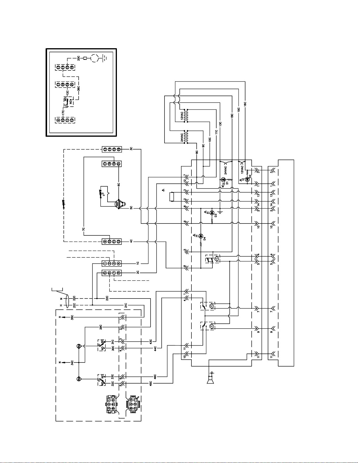
1.11 Wiring Diagrams
SOUND DEVICE
(FOR CONTROLLERS ONLY)
INSERT
8050382E
NOTE:
(1) CONNECT WIRE 21C FROM PIN 1 (20 PIN TERMINAL
BLOCK) DIRECT TO POWER SUPPLY.
(2) CONNECT WIRE 22C FROM PIN 5 (20 PIN TERMINAL
BLOCK) DIRECT TO POWER SUPPLY.
PILOT GENERATOR
HI-LIMIT T'STAT
SAFETY DRAIN OPTION (SEE INSERT)
PLAN WIRING DIAGRAM
OPTIONAL PRESSURE SWITCH
CAPACITOR
240/24V, 120/24V, 60HZ, 1Ø, 3 WIRE SERVICE
H TO NEXT FRYER
H TO FILTER
N TO NEXT FRYER
POWER SUPPLY WITHOUT
BASKET LIFT.
RIGHT
BASKET LIFT MOTOR
RIGHT
MICROSWITCH
LEFT
BASKET LIFT MOTOR
LEFT
MICROSWITCH
N TO FILTER
6 PIN CONNECTOR
PROBE
GAS VALVE RELAY
BASKET LIFT RELAY BASKET LIFT RELAY
INTERFACE BOARD
COMPUTER BASKET LIFT TIMER ANALOG CONTROLLER DIGITAL CONTROLLER
SOUND DEVICE
FOR COMPUTER OR
BASKET LIFT TIMER
OPTIONAL BASKET LIFT FOR 45 SERIES ONLY
DISCONNECT PLUG
ONLY.
1-36
Page 43

8050535B
INSET
SOUND DEVICE
(FOR CONTROLLERS ONLY)
THERMOCOUPLE
CAPACITOR
HI-LIMIT T'STAT
PROBE
PLAN WIRING DIAGRAM
CE 230V MJ45 W/COMPUTER AND BASKET LIFT
GAS VALVE
GAS VALVE RELAY
TO FILTER TERMINAL BLOCK
TO FILTER TERMINAL BLOCK
COMPUTER BASKET LIFT TIMER ANALOG CONTROLLER DIGITAL CONTROLLER
OPTIONAL BASKET LIFT FOR 45 SERIES ONLY
INTERFACE BOARD
SOUND DEVICE
FOR COMPUTER OR
BASKET LIFT TIMER
ONLY.
1-37
Page 44

OPERATING
THERMOSTAT
GAS VALVE
CAPACITOR
GAS VALVE
8050534D
PLAN WIRING DIAGRAM
HIGH LIMIT THERMOSTAT
THERMOCOUPLE
HIGH LIMIT
THERMOSTAT
ON/OFF SWITCHHEATING LIGHTMELT CYCLE SWITCH/LI GHT
CE FM/MJ 45 W/0 COMPUTER
THERMOCOUPLE
OPERATING THERMOSTAT
MELT CYCLE TIMER
SCREENED AREA FOR MELT CYCLE OPERATION
SOUND DEVICE
SAFETY DRAIN OPTION
DISCONNECT PLUG
MELT CYCLE SWITCH/LI GHT
ON/OFF SWITCH
HEATING LIGHT
TO NEXT FRYER
TERMINAL BLOCK
TO NEXT FRYER
TERMINAL BLOCK
POWER
TO BASKET LIFT (OPTIONAL)
TO FILTER
TO FILTER
1-38
Page 45

REPEAT SAME CIRCUIT ON NEXT FRYER IF NEEDED
SEE INSET A-A
FOR 50-2
8050385D
FILTER PUMP MOTOR
ON/OFF SWITCH
1 ST. FRYER - RIGHT OF FILTER
TO FRYER POWER SUPPLY
FOR (DIRECT) UNITS
INSET A-A
(DIRECT)
INSET B-B
PLAN WIRING DIAGRAM FOR FILTER MAGIC II
PUMP
RELAY
PUMP
HEATER
1 ST. FRYER - LEFT OF FILTER
FILTER PUMP MOTOR
ON/OFF SWITCH
REPEAT SAME CIRCUIT ON NEXT FRYER IF NEEDED
SEE INSET B-B
FOR 50-2
1-39
Page 46

PLAN WIRING DIAGRAM
45 SERIES BASKET LIFT SYSTEM
BASKET LIFT MOTOR
LEFT
MICROSWITCH
DISCONNECT PLUG
LEFT
MICROSWITCH
6 PIN CONNECTOR
6 PIN CONNECTOR
RIGHT
BASKET LIFT MOTOR
RIGHT
MILLIVOLT FRYER WIRING
TO 120V OR 240V
TRANSFORMER IN
FRYER
DISCONNECT PLUG
LEFT TIMER RIGHT TIMER
8050379E
1-40
Page 47

PLAN WIRING DIAGRAM
45 SERIES BASKET LIFT SYSTEM
BASKET LIFT MOTOR
LEFT
MICROSWITCH
DISCONNECT PLUG
LEFT
MICROSWITCH
6 PIN CONNECTOR
6 PIN CONNECTOR
RIGHT
BASKET LIFT MOTOR
RIGHT
MILLIVOLT FRYER WIRING
TO 120V OR 240V
TRANSFORMER IN
FRYER
DISCONNECT PLUG
LEFT TIMER RIGHT TIMER
8050379E
1-41
Page 48

THIS PAGE INTENTIONALLY LEFT BLANK.
Page 49

45 SERIES GAS FRYERS SERVICE AND PARTS MANUAL
CHAPTER 2: PARTS LIST
ACCESSORIES
1
5
6
7
14
11
12
13
4
3
8
9
10
ITEM PART # COMPONENT
1 803-0271 Basket, Twin
2 803-0099 Basket, Full (cannot be used with basket lifts)
3 803-0132 Basket Support Rack
* 803-0136 Basket Support Screen (screen w/handle used in place of Item 3)
* 803-0103 Sediment Tray
4 806-5518 Cover, Frypot or Holding Station
* 826-0993SP Handle Kit, Frypot Cover (includes handle and screws)
5 823-1885 Connecting Strip w/back plate (Burger King only)
6 910-4617 Connecting Strip (blunt point, ½” sides, 20.70” long)
7 910-2285 Connecting Strip (blunt point, 1” sides, 20.80” long)
8 910-7515 Connecting Strip (sharp point, ½” sides, 21.73” long)
9 910-7443 Connecting Strip (sharp point, 1” sides, 21.73” long)
10 910-7515SP Connecting Strip (sharp point, 1” sides, 21.84” long)
11 910-2572 Connecting Strip (sharp point, 3” sides, 21.84” long)
12 Gas Line, 1-Inch Dormont Flexible (includes Items 13 and 14)
806-1698SP 36-Inch (for gas line only (w/o Items 13 and 14), use 810-0088)
806-1699 42-Inch (for gas line only (w/o Items 13 and 14), use 810-0085)
13 810-0074 Quick-Disconnect Fitting, 1-Inch Male
14 810-0073 Quick-Disconnect Fitting, 1-Inch Female
* Not illustrated.
2
2-1
Page 50

BASKET LIFT ASSEMBLIES AND COMPONENT PARTS
Bell Crank Basket Lift
34
10 3 26
2
18
23
35
24
22
24
37
11
13
15
16
16
32
17
29
30
28
21
19
7
25
15
14
4
17
31
33
20
27
511
12
23
36
9
5
1
6
2-2
Page 51

ITEM PART # COMPONENT
1 Gear Motor, Basket Lift
807-0107 120VAC
807-0108 240VAC
2 807-0124 Bushing, Plastic
3 807-0240 Microswitch
4 826-1680 Clamp, Plastic Wire (Pkg. of 8)
5 826-1358 Nut, 6-32 Hex (Pkg. of 25)
6 809-0050 Nut, 2-32 Hex
7 809-0063 Nut, Jam ⅜-16 Hex
8 809-0076 Nut, ¼-20 x ¾ Expansion
9 809-0082 Ring, Truarc Retaining
10 809-0097 Screw, 6-32 X 1-inch Slotted Truss Head
11 809-0113 Screw, 2-32 X 1½-inch Slotted Truss Head
12 809-0127 Screw, ¼-20 X ½-inch Slotted Round Head
13 826-1370 Screw, ¼-20 X 1¼-inch Slotted Round Head (Pkg. of 10)
14 809-0155 Leveling Screw
15 809-0196 Washer, ⅜-inch Steel Flat
16 826-1381 Washer, Nylon (Package of 10 each 809-0203)
17 809-0360 Screw, 2-32 X ⅜-inch Slotted Hex Washer Head
18 826-1374 Screw, 10 X ½-inch Hex Washer Head (Pkg. of 25)
19 809-0480
Setscrew, ¼-28 X
5
⁄8-inch Hex Socket Head
20 810-0045 Bushing, Plastic
21 810-0052 Bellcrank and Cam
22 810-0170 Pin, Connecting
23 810-0172
Plug,
5
⁄8-inch Hole S/S
24 810-0192 Rod, Basket Lift
25 810-0220 Spacer, Tubular
26 812-0138 Insulation, Paper (Fishpaper)
27 813-0035 Bushing, Bronze
28 823-1419 Box, Electrical Wiring
29 900-4110 Angle, Bearing Support
30 910-0119 Cover, Electrical Wiring Box
31 910-3177 Panel, Stainless Steel Rear Access (for mild steel, use 900-3177)
32 910-3783 Cover, Stainless Steel Rear Cabinet (for mild steel, use 900-3783)
33 910-9361 Housing, Basket Lift Stainless Steel (for mild steel, use 900-9361
34 920-3233 Plate, Basket Lift Motor Mounting
35 920-6076 Link, Basket Lift
36 823-06931 Basket Lift Arm, Left
37 823-06932 Basket Lift Arm, Right
NOTE: See Page 2-20 for Roller Bracket Assembly.
2-3
Page 52

Modular Basket Lift
14
25
4 10 12 18
17
16
8
20135
14 22
24
NOTES:
1. Assemblies 106-1807SP (100-120V) and 106-1810SP (208-250V) do not
include Items 8, 16, 24, 25, and 26. These items must be ordered separately.
2. For 100-120V units, each individual resistor (807-2661) may be replaced or
the entire reistor assembly (806-8530SP) may be replaced.
3. For 208-250V units, the entire resistor assembly (106-2771 or 806-9185) must
be replaced.
4. Wiring has been omitted for clarity.
3 13
2114117
12105
(Before 11/02)
26
6
1592
19
2314
1
5
(After 10/02)
100-120V Configuration
208-250V Configuration
2-4
Page 53

ITEM PART # COMPONENT
1 Mount, Modular Basket Lift**
200-2942 For use on units with 12-pin connectors
900-7655 For use on units with 6-pin connectors
2 806-5964SP Motor Assembly, Modular Basket Lift***
3 807-2133
Capacitor, 12.5 µFarad, 250VAC Motor Run
4 807-2572 Microswitch
5 Resistor Assembly
806-8530SP 100-120V Modular Basket Lift (see Note 2 in illustration)
106-2771 208-250V Modular Basket Lift (before 11/02 use 806-9185; see illust. Note 3)
6 809-0082 Ring, Truarc Retaining
7 826-1361 Screw, 2-32 X 1-inch Slotted Truss Head (Pkg. of 25)
8 809-0127 Screw, ¼-20 X ½-inch Slotted Round Head
9 809-0186 Lock Washer w/External Teeth, #8
10 826-1366 Nut, 4-40 Hex Keps (Pkg. of 25)
11 809-0247 Nut, 2-32 Hex Keps
12 826-1359 Screw, 4-40 X ¾-inch Slotted Round Head (Pkg. of 25)
13 826-1371 Screw, #8 X ½-inch Hex Head Drill Point (Pkg. of 25)
14 826-1374 Screw, #10 X ½-inch Hex Head (Pkg. of 25)
15 809-0503 Screw, 2-32 X ½-inch Hex Head
16 810-0172
5
Plug,
⁄8-inch Stainless Steel Hole
17 810-1012 Rod, Modular Basket Lift
18 812-0442 Insulation, Microswitch
19 813-0035 Bushing, Bronze, .640” ID
20 816-0033 Tie Wrap, Screw Mount
21 900-5529 Gusset, Modular Basket Lift Motor
22 901-8499 Chassis, Modular Basket Lift, Left
23 902-8499 Chassis, Modular Basket Lift, Right
24 910-4776 Cover, S/S Modular Basket Lift (for CRS cover use 900-4776)
25 823-06931 Arm, Left Basket Lift
26 823-06932 Arm, Right Basket Lift
Basket Lift Assemblies (see Note 1 in illustration)
* 106-1807SP 100-120V w/o Relay
* 106-1810SP 208-250V w/o Relay
*** Not illustrated.
*** Basket lift assemblies manufactured prior to February 2002 have 6-pin connectors; those manufactured
February 2002 and later have 12-pin connectors. Verify the connector in use before ordering wiring
assemblies or mounts.
*** To replace stripped drive gear only, order 810-1013 (gear), 810-0973 (Woodruff key) and 809-0504
(setscrew).
NOTE: See Page 2-20 for Roller Bracket Assembly.
2-5
Page 54

BURNER ASSEMBLY COMPONENT PARTS
9
1
5
8
10
4
3
11
6
NOTE: Red dot indicates Propane/Butane Pilot
Assembly; green dot indicates Manufactured
Gas; no dot indicates Natural Gas.
5
7
2
2-6
Robertshaw gas valves (illustrated above)
are no longer available. Order kit
826-1596 to replace natural gas valves,
826-1597 to replace propane gas valves, or
826-1643 to replace manufactured gas valves.
Gas Valve Conversion Kits:
Non-CE Natural to Propane: 826-1143
Non-CE Propane to Natural: 826-1144
CE Natural to Propane: 826-1200
CE Propane to Natural: 826-1201
Page 55

ITEM PART # COMPONENT
y)
y
r
r
)
)
)
)
)
)
)
)
)
)
)
)
)
y
)
)
)
)
)
)
)
t
m
b
)
)
)
y
t
)
)
)
)
y)
)
)
)
1 806-0225SP Deflector (Target) Assembly (use 814-0034 for ceramic onl
2 826-1155 Ignitor Kit, Optional Piezo
807-1906 Electrode Assembl
810-1001 Trigge
3 823-0496 Manifold, Burne
4 Orifice
810-0407 Manufactured Gas, 2.15mm (0-1999 Ft
Natural Gas
826-1357 1.45mm (0-1999 Ft) (Pkg of 10
826-1386 1.40mm (2000-3999 Ft) (Pkg of 10
810-0361 1.36mm (4000-5999 Ft
810-0131 1.30mm (6000-7999 Ft
812-1301 1.27mm (8000-8999 Ft
810-0343 1.25mm (9000-10,000 Ft
Propane/Butane Gas
826-1387 0.86mm (0-1999 Ft) (Pkg of 10
810-0952 0.82mm (2000-3999 Ft
810-0339 0.81mm (4000-5999 Ft
812-0914 0.78mm (6000-7999 Ft
812-1302 0.76mm (8000-8999 Ft
812-0444 0.74mm (9000-10,000 Ft
5 Pilot Assembl
810-1830 Natural Gas, w/Thermopile (non-CE w/twin-leads
806-8688SP Natural Gas, w/Thermocouple (CE w/co-axial lead
810-0426 Natural Gas, w/o Thermopile or Thermocouple
810-0616 Propane or Butane Gas, w/Thermopile (non-CE w/co-axial lead
810-1773 Propane or Butane Gas, w/Thermopile (non-CE w/twin leads
806-8689SP Propane or Butane Gas, w/Thermocouple (CE
810-0427 Propane or Butane Gas, w/o Thermopile or Thermocouple
810-0683 Manufactured Gas, w/Thermocouple (CE and non-CE
6 823-0574 Shield Assembly, Burner Hea
7 Thermopile/Thermocouple
810-1873 Thermopile w/push-on terminals (used in non-CE Pilot Asse
826-1527 Kit, Thermocouple with adapter (used in CE Pilot Assemblies
812-1284 Thermocouple w/threaded terminal (component of 826-1527
8 Tube, Pilot Gas
810-0705 For use with all burner assemblies except Hong Kong export units
812-0278 For use with Hong Kong export units onl
9 810-0691 Tube, Ven
10 Valve, Gas (Non-CE) (see Note 1 below
* 810-0975 Knob, Gas Valve
807-3294 Natural Gas (for 240V, use 807-0025
807-3295 Propane/Butane Gas (for 240V, use 807-0759
807-3354 Manufactured Gas (other than Hong Kong export units
810-0353 Manufactured Gas (Hong Kong export units onl
11 Valve, Gas (CE
806-6710SP Natural Gas (see Note 2 below
806-6711SP Propane Gas (see Note 2 below
* Not illustrated.
lies
NOTES: 1. A gas valve capacitor (P/N 806-4781) is required on gas valves used on units with
Thermostat Controllers. 2. An adapter kit (P/N 812-1256SP) is required to connect the high-limit
thermostat to Item 11. See Page 2-34 for details.
2-7
Page 56

CABINET ASSEMBLIES AND COMPONENT PARTS
MJ145, F145 (Filter Ready), and Spreader Cabinet Assembly Components
5
2
Spreader Cabinet
1
(Typical)
3
6
9
7
2
Fryer Cabinet
1
(Typical)
See Page 2-9 for
access opening covers.
4
8
9
NOTES: Fryer and spreader cabinet assemblies are identical except for the backs — spreader
backs do not have a formed edge at the top. Cabinet sides with access openings are used on
F145 units or on spreader cabinets placed in batteries of fryers equipped with built-in filtration
systems.
NOTE: See Page 2-14 for casters, legs, and associated hardware, and Page 2-10 for holding station
pan components.
ITEM PART # COMPONENT
1 900-2568SP Base, Cabinet, One-Piece
2 900-4813SP Brace, Cabinet Top
3 Back, Spreader Cabinet
910-7213SP Stainless Steel
900-7213SP Aluminized Steel
4 Back, Fryer Cabinet
910-6983SP Stainless Steel
900-6983SP Aluminized Steel
5 Side, Left Cabinet w/o Access Openings
911-9323SP Stainless Steel
901-9323SP Enameled
6 Side, Right Cabinet w/o Access Openings
912-9323SP Stainless Steel
902-9323SP Enameled
7 Side, Left Cabinet w/Access Openings
911-9324SP Stainless Steel
901-9324SP Enameled
8 Side, Right Cabinet w/Access Openings
912-9324SP Stainless Steel
902-9324SP Enameled
9 826-1374 Screw, #10 X ½-inch Hex Washer Head (package of 25)
2-8
Page 57

MJ45 Batteries
6
8
9
4
7
3
2
5
1
(MJ345 ILLUSTRATED IS TYPICAL OF ALL)
NOTE: See Page 2-14 for casters, legs and associated hardware.
ITEM PART # COMPONENT
1 900-4426SP Channel, Left and Right Side
2 Channel, Front and Rear
900-2395SP Double
900-2396SP Triple
900-9373 Quad
3 900-6979SP Post, Door
4 Brace, Cabinet Top
900-7730SP Double
900-9430SP Triple
900-9318 Quad
5 806-5209SP Leg Pad Assembly
6 Side, Left Cabinet
911-9323SP
901-9323SP
7 Side, Right Cabinet
912-9323SP
902-9323SP
8 Back, Cabinet
910-6983SP Stainless Steel
900-6983SP Aluminized Steel
9 900-7326 Divider, Cabinet
10 826-1374 Screw, #10 X ½-inch Hex Washer Head (package of 25)
Stainless Steel (use 911-9324SP for side with access openings)
Enameled (use 901-9324SP for side with access openings)
Stainless Steel (use 912-9324SP for side with access openings)
Enameled (use 902-9324SP for side with access openings)
10
2-9
Page 58

FM45 Batteries with Built-In Filtration
1
2
NOTE: Items 1-15 are used in
all FM45 Builit-In Filter
configurations and therefore
4
3
7
22
1110
1312
15
6
5
9
28
20
are not repeated for the FM245
and FM145 (Filter on Right)
illustrations.
FM145 (FILTER ON LEFT)
(All components except Items 27 and
28 are the same for FM245 and FM345
1716
18
22
14
27
25
29
25
26
29
(See Page 2-9 for Leg Pad Assembly)
24
28
units with the filter on the left.)
8
FM245 (FILTER BETWEEN FRYERS)
(All components except Items 27 and 28
are the same for FM345 cabinets with
27
19
26
20
27
25
26
the filter between fryers.)
28
25
29
24
FM145 (FILTER ON RIGHT)
(All components except Items 27 and 28
are the same for FM245 and FM345
27
19
26
1716
23
21
units with the filter on the right.)
2-10
Page 59

ITEM PART # COMPONENT
1 910-7480 Trim, Filter Cabinet Top
2 806-8274SP Pan Assembly, Filter/Spreader Cabinet
3 900-7277 Support, Drain Pan
4 Back w/Access Opening, Filter Cabinet
910-7274SP Stainless Steel
900-7274SP Aluminized Steel
5 900-4089 Cover, Cabinet Back Access
6 Back, Cabinet
910-6983SP Stainless Steel
900-6983SP Aluminized Steel
7 Side, Left Cabinet
911-9323SP Stainless Steel
901-9323SP Enameled
8 Side, Right Cabinet
912-9323SP Stainless Steel
902-9323SP Enameled
9 900-7414 Shield, Filter Magic Pan
10 900-6979SP Post, Door
11 809-0413 Spacer, .25 x .160 8 Gauge Nylon (located behind Item 10 at bottom)
12 900-4391SP Brace, Front Cabinet
13 826-1379 Screw, #10 x ½-inch Philips Truss Head (package of 10)
14 900-1700 Bracket, Drain Support
15 900-7314SP Divider, Cabinet
16 910-1601 Leg, Filter
17 900-1621 Plate, Rail Mount (located inside front edge of Item 7)
18 901-1599 Bracket, Left Pan Rail (used on cabinets with filter on left)
19 901-1595 Bracket, Left Pan Rail (used on cabinets with filter on right or in middle)
20 902-1599 Bracket, Right Pan Rail (used on cabinets with filter in middle)
21 902-1595 Bracket, Right Pan Rail (used on cabinets with filter on right)
22 901-4390 Channel, Left Filter Side
23 902-4390 Channel, Right Filter Side
24 806-4917 Rail Assembly, Filter Magic
25 900-4426 Channel, Fryer Outside
26 900-4383 Channel, Fryer Inside
27 Channel, Fryer Front
900-2394 Single Fryer
900-2395 Double Fryer
900-2396 Triple Fryer
28 Channel, Filter Magic Cabinet Rear
900-1631 FM145 Filter Left
900-7243 FM245 Filter Left
900-9319 FM345 Filter Left
900-1630 FM145 Filter Right
900-7244 FM245 Filter Right
900-9322 FM345 Filter Right
900-7242 FM245 Filter Middle
900-9321 FM345 (Fryer, Fryer, Filter, Fryer)
900-9320 FM345 (Fryer, Filter, Fryer, Fryer)
29 826-1374 Screw, #10 X ½-inch Hex Washer Head (package of 25)
2-11
Page 60

Filter Magic II Add-On Cabinet Components
31
3
29
1
20
18
4
30
29
2
9
25
24
23
10 19
22
14
12
21
14
28272625
7
5
20
22
12
13
18
18
14
15
16
17
ADD-ON
FILTER MAGIC CABINET
8
6
11
15
16
21
14
13
18
17
UNDERCOUNTER ADD-ON
FILTER MAGIC CABINET
2-12
Page 61

ITEM PART # COMPONENT
1 Side, Left Cabinet, w/Access Openings
911-9324SP Stainless Steel
901-9324SP Enameled
2 Side, Right Cabinet, w/Access Openings
912-9324SP Stainless Steel
902-9324SP Enameled
3 Back w/Access Opening, Filter Cabinet
910-7274SP Stainless Steel
900-7274SP Aluminized Steel
4 Cover, Cabinet Back Access
910-4089 Stainless Steel
900-4089 Aluminized Steel
5 Side, Left Undercounter Cabinet
911-7677SP Stainless Steel
901-7677SP Enameled
6 Side, Right Undercounter Cabinet
912-7677SP Stainless Steel
902-7677SP Enameled
7 Back, Undercounter Cabinet
910-4786 Stainless Steel
900-4786 Aluminized Steel
8 910-7680 Cover, Undercounter Cabinet
9 900-4813SP Brace, Cabinet Top
10 900-4391SP Brace, Cabinet Front
11 900-4785 Brace, Undercounter Cabinet Top and Center
12 806-5317SP Rail Assembly
13 806-4897SP Base Assembly (includes leg pad assembly 806-5209 (see Page 2-13))
14 900-1621 Plate, Rail Mount (located inside lower front edge of Items 1, 2, 5, and 6)
15 910-1601
16 810-0007 Leg, Adjustable
17 910-1832 Retainer, Leg Insert, Full Height
18 826-1374 Screw, #10 X ½-inch Hex Washer Head (Pkg. of 25)
19 826-1379 Screw, #10 X ½-inch Philips Truss Head (Pkg. of 10)
20 Cover, 4-inch X 4-inch Access Opening
910-0889 Stainless Steel
900-0889 Enameled
21 Cover, 4-inch X 4-inch Access Opening
910-0890 Stainless Steel
900-0890 Enameled
22 809-0359 Screw, #8 X ¼-inch Hex Washer Head (for access covers)
23 900-7414 Shield, FM Pan
24 900-4175 Mount, Motor
25 826-1362 Nut, ¼-20 Hex (Pkg. of 10)
26 809-0429 Bolt, ¼-20 X 2-inch Hex Head
27 809-0191 Washer, ¼-inch Lock
28 810-0665 Nut, ¼-20 Hex Leveling
29 900-7277 Support, Holding Station Pan
30 806-8274SP Pan Assembly, Holding Station
31 910-7480 Trim, Holding Station
Leg, Filter Cabinet (use 910-8673 on units with rear casters)
2-13
Page 62

CASTERS, LEGS, AND ASSOCIATED HARDWARE
1 2
6
3
7
8 9
2
5
ITEM PART # COMPONENT
1 823-2669 Caster, 3” Swivel w/Brake (optional substitute for front leg in FM add-on cabinet)
2 826-1130 Caster, 3” Swivel w/Brake (810-0651 and mounting hardware)
3 826-1118 Caster, 5” Swivel w/Brake (810-0357 and mounting hardware)
4 826-1117 Caster, 5” Swivel w/o Brake (810-0356 and mounting hardware)
5 826-1138 Caster, 5” Rigid w/o Brake (810-0378 and mounting hardware)
6 826-1237 Leg Assembly, Stainless Steel
7 826-1115 Leg Assembly, Nickel Plated
8 826-1095 Anchor Strap Kit (for use on single fryers w/legs)
9 826-0900 Chain Restraint Kit (for use on fryers w/casters)
* 826-1113 Kit, Mounting Hardware, 1 Caster/Leg (4 mounting bolts and lock washers)
* 826-1098 Kit, Mounting Hardware, 2 Casters/Legs (8 mounting bolts and lock washers)
* 826-1043 Kit, Mounting Hardware, 4 Casters/Legs (16 mounting bolts and lock washers)
* Not illustrated.
NOTE: Items 2 through 8 include 1 caster or leg, 4 mounting bolts, and 4 lock washers.
2-14
Page 63

COMPONENT SHIELDS, FILTER BOX ASSEMBLIES, AND COMPONENT PARTS
)
)
)
t
t
t
g
)
)
y
y
y
y
y
y
)
g
)
)
4 6 7 8
2 3
9
11 3
12 3
14 15 16
5
1
Non-CE Shields CE Shield
Component Shield Assemblies with Interface Boards
8764
5
1
2 3
17 18 20 21
9
13 3
ITEM PART # COMPONENT
Complete Shield Assemblies
806-4773SP 100-120V, 50/60 Hz (Non-CE
806-4775SP 208-240V, 50/60 Hz (Non-CE
806-6629SP 230V, 50 Hz (CE
Components
1 900-4340 Shield, Componen
2 824-0161 Support, Interface Board
3 809-0360 Screw, #8 X ⅜-inch Washer Slotted Hex Head
4 Interface Board
806-3548 Non-CE Universal Replacemen
806-7505 CE Universal Replacemen
5 807-1582 Relay, 12VDC
* 810-2243 Clip, Relay Retainin
6 809-0349 Spacer, 4 x 6 mm, Interface Board Standoff
7 809-0096 Screw, 6-32 X ⅝-inch Slot Head
8 809-0250 Nut, 6-32 Hex Keps
9 807-2469 Bushing, Heyco (fits ⅞-inch (.875-inch) hole
10 810-0045 Bushing, Heyco (fits 1.25-inch hole
11 Transformer, 12V Secondar
807-0855 100-120V 50/60 Hz Primar
807-0979 208-240V 50/60 Hz Primar
12 Transformer, 24V Secondar
807-0800 100-120V 50/60 Hz Primar
807-0680 208-240V 50/60 Hz Primar
13 807-1999 Transformer, 208-240V Primary/12V and 24V Secondary Dual Voltage
14 807-0066 Terminal Block, 20-Position
15 809-0097 Screw, 6-32 X 1-inch Slotted Round Head
16 826-1358 Nut, 6-32 Hex (Pkg. of 25
17 816-0217 Paper, Insulatin
18 810-1164 Terminal Block, 6-Position
19 810-1168 Terminal Block, 8-Position
20 826-1359 Screw, 4-40 X ¾-inch Slotted Round Head (Pkg. of 25
21 826-1366 Nut, 4-40 Hex Keps (Pkg. of 25
* Not illustrated.
10
212019
2-15
Page 64

20
Electromechanical timer shown for
identification purposes only. This
timer has been replaced by Items
17, 18, and 19 (shown in the 100-
120V illustration) in all applications.
19
17
1813
14
1
10 13
2 3 4
100-120V Non CE
13 16
11 1314
20
1
2 3 4
208-240V Non-CE
NOTE: Melt cycle timers (Items
16 and 17) are not present in
shield assemblies 806-4774SP,
806-4776SP, and 806-6630SP.
19
1813
20
17
14
12 13
15
7 8 9
9865
208-240V CE
Component Shield Assemblies without Interface Boards
2-16
1
Page 65

ITEM PART # COMPONENT
Complete Shield Assemblies
806-4774SP 120V, 50/60 Hz without Melt Cycle Timer (Non-CE)
806-4776SP 240V, 50/60 Hz without Melt Cycle Timer (Non-CE)
806-4772SP 120V, 50/60 Hz with Melt Cycle Timer (Non-CE)
806-4777SP 240V, 50/60 Hz with Melt Cycle Timer (Non-CE)
806-6630SP 230V, 50 Hz without Melt Cycle Timer (CE)
806-6632SP 230V, 50 Hz with Melt Cycle Timer (CE)
Components
1 900-4340 Shield, Component
2 807-0066 Block, Terminal, 20-Pin
3 809-0097 Screw, 6-32 x 1-inch Slotted Truss Head
4 826-1358 Nut, 6-32 Hex (Pkg. of 25)
5 816-0217 Paper, Insulating
6 810-1164 Terminal Block, 6-Position
7 810-1168 Terminal Block, 8-Position
8 826-1359 Screw, 4-40 X ¾-inch Slotted Round Head (Pkg. of 25)
9 826-1366 Nut, 4-40 Hex Keps (Pkg. of 25)
10 807-0800 Transformer, 100-120V Primary/24V Secondary 50/60 Hz 50VA
11 Transformer, 208-240V Primary/24V Secondary 50/60 Hz
807-0680 20VA without fuse
807-2180 50 VA with fuse
* 807-1597 Fuse, 3-Amp Slow-Blow (for use w/transformer 807-2180)
12 807-1999 Transformer, 208-240V Primary/12V and 24V Secondary Dual Voltage
13 826-1374 Screw, #10 x ½-inch Hex Washer Head (Pkg of 25)
14 810-0045 Bushing, Heyco (fits 1.25-inch hole)
15 807-2469 Bushing, Heyco (fits ⅞-inch (.875-inch) hole)
16 826-1546 Kit, Melt Cycle Timer (Items 17, 18, and 19) replaces electromechanical timer
17 806-9613 PC Board Assembly, Melt Cycle Timer (50 and 60 Hz)
18 900-8741 Bracket, Melt Cycle Timer
19 809-0580 Standoff, PC Board
20 807-0156 Plug, 9-Pin
* Not illustrated.
2-17
Page 66

Filter Boxes
y
13 16 17
543
or
171614
1
2
19
3 4 5
Non-CE Standard
18
1776
19
121198
19
15 16 17
Non-CE
18
1776
18
171613
or
171614
CE Standard
3 4 5
10 11 12
Undercounter
ITEM PART # COMPONENT
Complete Box Assembl
806-4359SP 100-120V Standard Cabinet
806-4360SP 208-240V Standard Cabinet (Non-CE)
806-6709SP 230V Standard Cabinet (CE)
806-4361SP 100-120V Undercounter Cabinet
806-4362SP 208-240V Undercounter Cabinet (Non-CE)
Components
1 200-0409 Box, Standard Filter Control
2 200-0410 Box, Undercounter Filter Control
3 807-0012 Relay, 15 Amp, SPST, Filter
4 809-0096 Screw, 6-32 X ⅝-inch Slot Head
5 826-1358 Nut, 6-32 Hex (Pkg. of 25)
6 807-0276 Terminal Block, 20-Position
7 809-0097 Screw, 6-32 X 1-inch Slotted Round Head
8 816-0217 Paper, Insulating
9 810-1164 Terminal Block, 6-Position
10 810-1168 Terminal Block, 8- Position
11 826-1359 Screw, 4-40 X ¾-inch Slotted Round Head (Pkg. of 25)
12 826-1366 Nut, 4-40 Hex Keps (Pkg. of 25)
13 807-0800 Transformer, 100-120V Primary/24V Secondary 50/60 Hz 50VA
14 807-0680 Transformer, 208-240V Primary/24V Secondary 50/60 Hz 20VA
15 807-1999 Transformer, 208-240V Primary/12V & 24V Secondary Dual Voltage (CE)
16 809-0103 Screw, 8-32 X ½-inch Slotted Truss Head
17 809-0050 Nut, 8-32 Hex
18 807-0124 Bushing, Heyco (fits ⅞-inch (.875-inch) hole)
19 809-0360 Screw, #8 X ⅜-inch Washer Slotted Hex Head
2-18
Page 67

THIS PAGE INTENTIONALLY LEFT BLANK
2-19
Page 68

CONTROL PANEL ASSEMBLIES, FLUE CAPS, TOP CAPS, and RELATED ITEMS
653
652
651
657
4
17
16
15
23
22
21
27
26
25
8
13
12
11
10
9
14
18
19
20
28
30
29
24
2-20
Page 69

ITEM PART # COMPONENT
1 810-1403 Basket Hanger, Wire Form
* 809-0921 Spacer, Wire Form Basket Hanger
2 Basket Hanger, Extruded Aluminum (No longer available; use 810-1403)
3 823-1462 Basket Hanger, Burger King
4 106-2185 Bracket, Burger King Easy-Off Basket Hanger (used w/Item 1)
5 809-0171
6 826-1351 Nut, Cage (receives Basket Hanger Thumbscrew) (pkg of 10)
7 806-9257SP Roller Assembly, Basket Lift (Complete)
8 910-8284 Bracket, One-Piece Roller Guide
9 826-1334 Capscrew, ¼ – 20 x 1¼” Stainless Steel Hex Head (pkg of 5)
10 809-0190 Washer, ¼” Stainless Steel Flat
11 810-0374 Spacer, Tubular
12 810-0194 Roller, Basket Lift Guide
13 809-0047 Nut, ¼ – 20 Cap (also used w/Item 4)
14 Flue Cap, Single Fryer, w/lip
910-5018 Standard
910-6545 Optional (without lip along flue opening)
823-3749 Burger King with Button Studs (used w/Item 4)
15 Flue Cap, 2-Fryer Battery
823-2540 Standard
823-3536 Burger King with Button Studs (used w/Item 4)
16 Flue Cap, 3-Fryer Battery
823-2541 Standard
823-3537 Burger King with Button Studs (used w/Item 4)
17 823-2569 Flue Cap, 4-Fryer Battery
18 900-5486 Support, Flue Cap
19 900-4253 Flue Cap Retaining Strip
20 824-0404 Top Cap, Single Fryer
21 824-0405 Top Cap, Two-Fryer Battery
22 824-0406 Top Cap, Three-Fryer Battery
23 824-0407 Top Cap, Four-Fryer Battery
24 806-4732SP Control Panel Assembly, Single Fryer
25 806-4733SP Control Panel Assembly, 2-Fryer Battery
26 806-4734SP Control Panel Assembly, 3-Fryer Battery
27 806-5018SP Control Panel Assembly, 4-Fryer Battery
28 910-8503 Panel, FM Standard Cabinet Front
29 910-8505 Panel, FM Undercounter Cabinet Front
30 910-3557 Flue Deflector
* 826-1379 Screw, #10 X ½-inch Philips Head (pkg of 10) (attaches top cap)
* 826-1371 Screw, #8 X ½-inch Hex Washer Head (pkg of 25) (attaches flue cap)
* Not illustrated.
Thumbscrew, ¼-20 X 1⅜-inch Basket Hanger
2-21
Page 70

CONTROLLER ASSEMBLIES (Thermostat Controllers)
CONTROLLER WITHOUT TIMERS
12
13
26
CONTROLLER WITH MECHANICAL TIMERS
13
6
CONTROLLER WITH ELECTRIC TIMERS
NOTE: Thermostat shaft and
associated components are the
same for all configurations.
8
2
11
2
17
12
11
7
10
13
10
3
9
2
12
9
4
17
1
14
27
1
15
16
23
25
19
18
5
21
24
1
11
20
22
10
9
27
2-22
Page 71

ITEM PART # COMPONENT
1 802-0765 Label, Control Panel
2 802-1470 Label, Thermostat Dial
3 802-1473 Label, 15-Minute Mechanical Timer Bezel
4 910-1551 Bezel, 15-Minute Mechanical Timer
5 810-0334 Knob, Operating Thermostat
6 810-1287 Knob, 15-minute Mechanical Timer
7 810-1822 Knob, 15-Minute Electrical Timer Replacement
8 810-1823 Push Button, White 15-Minute Electrical Timer Replacement
9 807-1525 Light, White Melt Cycle Indicator, 24V
10 807-3498 Switch, Melt Cycle Rocker, 24V
11 807-3575 Plug, Blank Switch (used on units without melt cycle option)
12 826-1395 Plug, Snap-in Reducer, S/S (Pkg of 10)
13 826-1338 Bushing, Plastic, Thermostat Shaft (Pkg of 25)
14 810-0585 Timer, 15-minute Mechanical Basket Lift
15 Timer, 15-Minute Electrical Basket Lift
826-1552 100-120V
807-0401 208-240V
16 950-0246 Insulation, Double Electric Timer
17 809-0093 Screw, 6-32 X 3/16-inch Slotted Flat Head
18 810-0276 Adapter, Shaft End
19 810-0999 Shaft, Flexible
20 809-0157 Set Screw
21 826-1361 Stop Screw (Pkg of 25)
22 809-0050 Nut, 5-32 Hex
23 900-2241 Bracket, Thermostat
24 900-2071 Bracket, Thermostat Shaft Guide
25 826-1371 Screw, #8 X ½-inch Slotted Hex Washer Head (Pkg. of 25)
26 910-4345 Panel, Thermostat Control without Timers
27 910-4344 Panel, Thermostat Control with Electric or Mechanical Timers
* 802-0336 Label, Frymaster Logo
* 806-4797 Alarm, Open Drain (Buzzer)
* Not illustrated.
NOTE: See Pages 2-16 and 2-17 for melt cycle timers.
2-23
Page 72

CONTROLLER ASSEMBLIES (Other than Thermostat Controllers)
1 2 3
ITEM PART # COMPONENT
1 Computer Magic III
106-1149SP Built-In, Non-CE
106-1199SP Built-In CE
106-1216 Remote LP03
106-1218 Remote On-Hood
106-1230 Remote In-Hood
2 106-2079SP Controller, Basket Lift Timer
3 Controller, Digital
106-1501 Non-CE
106-1505 CE
4 806-3559
* 910-3690
* 806-3660
Controller, Solid State (controller knob is 810-0387)
Panel, Blank Control (for use on fryers with remote computers)
Sound Device (for use w/all CM III Computers)
* 826-1379 Screw, #10 X ½-inch Philips Truss Head (computer screws) (Pkg. of 10)
* 826-1032SP Kit, Control Panel Screws (2 screws and 2 screw retainers)
* Not illustrated.
4
SOLID STATE
2-24
Page 73

DOOR ASSEMBLY
1
4
7
5
5
2
3
6
ITEM PART # COMPONENT
806-8320
806-6405SP
Door Assembly Complete, Enameled Steel (does not include Items 3 and 5)
Door Assembly Complete, Stainless Steel (does not include Items 3 and 5)
1 106-0554SP Door Pin Assembly
2 826-1343 Spring, Door Pin
3 810-1422
Handle, Door, Wireform, Stainless Steel (must be ordered separately)
4 826-1379 Screw, #10 x ½” Phillips Head, Zinc Plated
5 810-1508
Hinge, Door, Universal (must be ordered separately)
6 824-0616SP Panel, Door, Outer
7 900-4807 Liner, Door
* 810-1105 Magnet, Door
* Not illustrated.
2-25
Page 74

DRAIN AND FILTRATION SYSTEM COMPONENTS
Drain System Components
15
18
20
19
28
14
29
30
6
5
7
27
31
32
17
21
25
26
washers
Compression
23
24
Steel flat washer
over plastic washer
9
10
4
2
1
3
8
12
13
11
22
33
2-26
Page 75

Item Part # Component
* 826-0877 Kit, Clamp Service (Contains 2 each of Items 1-3 and 1 of Item 4)
1 810-0396 Clamp Section (Requires 2 per connection)
2 809-0071 Nut, ¼–20
3 826-1375 Screw, 10–32 X ¾
4 816-0032 Seal (Connection Gasket)
5 826-1348 Cover, Clean-out (Pkg. of 5)
6 816-0021 Gasket, Clean-out
7 826-1382 Wing Nut, Clean-out Cover Retaining (Pkg. of 10)
8 900-0757 Cover, Drain End
9 823-0717 Full Vat, 15.5-inches Long
10 823-0718 End, Full Vat, 8.12-inches Long
* 813-0284 Nipple, 1-inch x ¾-inch (connects drain valve to drain tube)
11 Grommet, Drain Tube
816-0092 1.50-inch I.D.
816-0091 1.75-inch I.D. (used on FM I units built prior to February 1990 only)
12 826-1345
Washer, Drain Tube Retaining (Pkg of 25) (1⅜-in. ID x 23/
13 809-0347 Nut, Drain Tube Retaining
14 823-0731 Extension, Spreader Cabinet, 15.5-inches Long
15 823-0719 Drain Outlet, Fixed
16 806-4068 Drain Outlet Assembly, Swivel
17 823-1091 Drain Tube, Swivel
18 816-0083 O-Ring, 2.5-inches ID
19 823-1092 Collar, Drain
20 810-0388 Knob, Clamping
21 809-0115 Screw, 10–32
22 810-1569 Valve w/Handle, 1.25-inch Drain (for use on MJ45 units)
23 810-1568 Handle w/Lock, Drain Valve
24 810-1020 Valve, 1.25-inch Drain (for use on FM45 units)**
25 806-8137 Bracket, Drain Safety Switch
26 816-0220 Insulation, Drain Safety Switch
27 807-2103 Switch, Drain Safety
28 900-2841 Cover, Drain Safety Switch
29 809-0237 Nut, 4-40 Keps Hex
30 809-0540 Nut, ½-inch 2-Way Lock
31 810-0820 Handle, Drain Valve w/o Lock
32 816-0211 Sleeve, Drain Valve Handle
33 812-1226SP Extension, Drain
** Not illustrated.
** For old-style valve with welded-on switch bracket, use 823-1363.
16
-
in. OD)
2-27
Page 76

Filter Magic II Filter Pan Assemblies
9
10
11
8
7
12
1
Fitting on outside
bottom of inner pan.
8
6
4
5
3
7
BA
Item Part # Component
A 806-9255SP
823-2751SP One-Piece Filter Pan
B 806-6093SP
806-4338SP Outer Pan Assembly (Items 1, 3, 4, 5, 7, 8, and 806-4373)
1 823-1360SP Outer Pan
806-5282SP Inner Pan Assembly (Items 2, 6, 10, 11, and 12)
2 823-1731SP Inner Pan
3 823-1361 Base, Filter Pan Assembly
4 824-0291 Cover, Suction Tube
5 910-1350 Clamp, Suction Tube
6 816-0117 O-Ring, .609 OD
* 806-4373 Heater Strip Assembly
* 811-0861 Insulation, Foam (50-foot/15m roll
* 811-0746 Tape, Aluminum Insulation (50-yard/46m roll)
7 810-0005 Caster, Rigid
8 810-0006 Caster, Swivel
9 824-0416 Crumb Screen
10 810-1406 Hold Down Ring Assembly
11 900-8827 Sanagrid Filter Screen
12 810-0180 Handle, Filter Pan
* 803-0170 Paper, Filter (100 sheets)
* 803-0002 Powder, Filter (80 1-cup applications)
* Not illustrated.
One-Piece Filter Pan Assembly (Items 7, 8, 10, 11, and 12)
Two-Piece Pan Assembly (Unique components are listed below.)
Components Used in Both Designs
9
10
11
2
12
2-28
Page 77

FRYPOT ASSEMBLIES AND COMPONENT PARTS
15
1
12
2
11
16
6
14
7
8
9
1817
16
13
10
12
5
4
3
11
ITEM PART # COMPONENT
1 Frypot Assemblies, Complete (Items 2, 3, 5, 6, and 10-18)
106-2549SP Stainless Steel
806-3810SP Cold Rolled Steel
2 Frypot Assembly, without Insulation
823-3887SP Stainless Steel (integral component of 106-2549SP)
823-0921SP Cold Rolled Steel (integral component of 806-3810SP)
3 806-5778SP Flue Deflector Box Assembly,
4 810-0424 Deflector, Rear Burner (integral component of Item 3)
5 806-5567SP Flue Assembly
6 806-1095SP Front Baffle Assembly
7 809-0409 Screw, Pilot Light Cover (integral component of Item 6)
8 810-0647 Holder, Pilot Light Cover Screw (integral component of Item 6)
9 900-1090 Cover, Pilot Light (integral component of Item 6)
10 806-5566SP Rear Combustion Chamber Panel Assembly
11 900-6441 Panel, Combustion Chamber Side
12 812-0249 Insulation, Frypot Side, Outer Layer
13 812-0248 Insulation, Frypot Side, Inner Layer
14 816-0602 Insulation, Kaowool Blanket, ½ X 14 X 4 (trim to fit)
15 812-0269 Insulation, Kaowool Blanket, ½ x 14 x 14
16 826-1374 Screw, #10 X ½-inch Washer Hex Head (Pkg. of 25)
17 809-0173 Clip, Tinnerman
18 809-0170 Screw, #14 X ¾-inch Slotted Pan Head
2-29
Page 78

OIL RETURN PLUMBING AND HANDLE COMPONENTS
clarity.
Item shown
disproportionately large for
9
20
8
9
8
8
8
11
6
8
5
4
3
8
7
10
13
12
16
15
1
Disconnect Components
Detail of Motor, Pump, and
2
4
18
19
17
14
2-30
Page 79

ITEM PART # COMPONENT
1 Pump Motor
826-1712 100-120 VAC 50/60Hz (includes gasket 816-0093)
826-1756 208 VAC 50/60 Hz (includes gasket 816-0093)
826-1270 230-250 VAC 50/60 Hz (includes gasket 816-0093)
* 806-6728SP Pump Motor Wiring Assembly (used with above motor kits)
2 826-1264 Pump, 4 GPM (15 LPM) (includes gasket 816-0093 and mounting screws)
3 813-0265 Nipple, ½-inch x 2 ½-inch
4 813-0062 Elbow, ½-inch x 90º
5 813-0368 Nipple, ½-inch x 16-inch
6 813-0156 Pipe Plug, ½-inch
7 813-0003 Tee, ½-inch
8 810-1057 Flexline, 13-inch Oil Return (has female ends)
* 810-1668 Adapter, Male (used with Item 8; two required)
9 813-0275 Nipple, ½-inch x 9-inch
10 810-0278 Valve, ½-inch Ball
11 902-0883 Handle, Valve
12 813-0165 Elbow, ½-inch x 90º Street
13 813-0022 Nipple, ½-inch Close
14 823-1356 Disconnect Fitting
15 826-1392 O-Ring (pkg of 5)
16 816-0102 Grommet, Oil Diverter
17 900-1472 Diverter, Oil
18 910-1627 Bracket, Male Disconnect Support
19 813-0330 Bushing, ½-inch NPT to ½-inch Tube
20 806-4694SP Contactor Block Assembly
* 813-0117 Nipple, ½-inch x 3½-inch
* 807-1600 Thermal Switch, 100-120V Baldor Motors
* 807-1601 Thermal Switch, 200-250V Baldor Motors
* 807-1598 Thermal Switch, 100-120V Magnatek Motors
* 807-1599 Thermal Switch, 200-250V Magnatek Motors
* 807-2016 Wiring Harness, Controller to Filter
* 807-1408 Heater Strip, 120VAC 50W, 70-inch
* 807-2050 Heater Strip, 250VAC 90W, 70-inch
* 811-0746 Tape, Aluminum (2-inch x 50-yard (46m) roll)
* Not illustrated
2-31
Page 80

THROUGH MARCH 2001 APRIL 2001 AND LATER
10
7
12
15
10
8
16
2
13
14
9
4
5
11
3
6
11
1
12
3
13
18
14
17
19
8
10
9
11
5
6
21
20
15
1
16
22
ITEM PART # COMPONENT
1 807-2103 Microswitch
2 930-0839 Bracket, Microswitch
3 810-1999 Bracket, Valve Handle
4 900-1853 Handle, Oil Return
5 814-0047 Sleeve, Handle
6 900-0239 Arm, Oil Return Valve
7 920-0220 Linkage, Oil Return Valve
8 809-0200 Washer, Flat
9 826-1381 Washer, Nylatron (Pkg of 10)
10 810-0220 Spacer, Tubular, .493 OD
11 809-0142 Screw, 5/16 – 24 x ¾” Hex Head
12 809-0056 Nut, 5/16 – 24, Hex Head, Nylon Lock
13 809-0104 Screw, 4 – 32 x ½” Slotted Truss Head
14 809-0247 Nut, Keps Hex, 8 – 32
15 826-1359 Screw, 4 – 40 x ¾” Slotted Pan Head (Pkg of 25)
16 826-1366 Nut, Keps Hex, 4 – 40 (Pkg of 25)
17 200-0938 Handle, Oil Return
18 810-1165 Washer, Teflon 0.372 I.D. X 0.753 O.D.
19 810-0285 Swivel, Oil Return Linkage Rod
20 200-1059 Rod, Oil Return Linkage
21 809-0601 Clip, Clevis
22 200-0821 Bracket, Microswitch
2-32
Page 81

POWER SHOWER ASSEMBLY
1
5
4
2
ITEM PART # COMPONENT
1 806-4503SP
Power Shower Assembly, Complete
2 809-0415 Screw, Cleanout
3 826-1344 O-Ring (Pkg of 5)
4 826-1390 Seal (Gasket) (Pkg of 5)
5 814-0001 Grip, Handle
3
2-33
Page 82

TEMPERATURE PROBE, THERMOSTATS, AND RELATED COMPONENTS
9
1
2
4
8
4
3
7
ITEM PART # COMPONENT
1 806-4206 Temperature Probe, Minco
2 826-1177
3 806-7550
Thermostat, Non-CE 425°F High-Limit (see NOTE 1)
Thermostat, CE 218°C High-Limit (see NOTE 2)
4 807-2274 Thermostat, High Limit
5 807-0280 Adapter, High-Limit Thermostat (used only with Robertshaw gas valves)
6 812-1256SP Adapter Kit, High-Limit Thermostat to Honeywell Gas Valve
7 806-3910 Thermostat Assembly, Navy High-Limit (push-button reset)
8 806-0183 Thermostat Assembly, Operating
9 210-0681 Probe Guard
5
6
NOTE 1: Kit 826-1177 (Item 2) contains high-limit thermostat 807-7224 (Item 4), Adapter
807-0280 (Item 5) and an assortment of connectors to allow it to be configured for use on several
different Robertshaw valves.
NOTE 2: Assembly 806-7550 (Item 3) contains high-limit thermostat 807-2274 (Item 4) and
screw-in gas valve adapter kit 812-1256SP (Item 6) for connection to Honeywell gas valves.
2-34
Page 83

WIRING ASSEMBLIES/HARNESSES AND REMOTE CABLE ASSEMBLIES
Wiring Assemblies and Harnesses
806-2079SP 100-120V Basket Lift Universal Motor (6-Pin female w/6 wires plus 1 separate wire)
806-8555SP 208-240V Modular Basket Lift Motor (6-Pin female w/6 wires plus 4 separate wires)
106-1822SP 100-120V Modular Basket Lift Motor (12-pin female w/5 wires)
106-1804SP 208-250V Modular Basket Lift Motor (12-pin female w/5 wires plus 3 separate wires)
806-4798SP Basket Lift Power, Non-CE (6-pin male w/6 wires; connects to 806-2079SP or 806-8555SP)
806-6708SP Basket Lift Power, CE (6-pin male plus 806-4798)
807-3699 Basket Lift Power, Non-CE/CE (12-pin male w/6 wires, connects to 106-1822SP or 106-1804SP)
806-9777SP Thermostat Control Universal (control panel-end connections)
806-9778SP Thermostat Control Universal (component shield-end connections)
806-9779SP Basket Lift Universal (control panel-end connections)
806-9780SP Basket Lift Universal (basket lift-end connections)
806-9781SP Wiring Bundle, Component Shield to Controller and Fryer Components (21-wire bundle)
826-1560 Kit, 45 Series Wiring (contains 806-9777SP through 806-9781SP)
806-3549SP Interface Board (interface board to fryer components; 12-pin male w/5 wires)
806-6705SP CE Non-Direct Wiring Power Supply (power cords joined in junction box)
806-4214SP Fryer to Fryer Drain Safety Switch (2-pin male w/two wires and 2-pin female w/two wires)
806-4215SP Fryer to Filter Drain Safety Switch (2-pin male w/two wires and 2-pin female w/two wires)
NOTE: Assemblies 806-2079SP, 806-9777SP through 806-9781SP and kit 826-1560 are
“universal” in nature. That is, they contain all wires and connectors necessary for all configurations
of the application described. Consequently, there may be “extra” wires that are not needed in a
particular configuration. Any extra wires should be removed when the assemblies are installed to
preclude later confusion.
Remote Computer/Controller to Interface Board Cables
Each of these assemblies has two 15-pin male connectors, and a 15-wire cable looped through a ferrite ring.
Only the length of the cable varies.
806-2071 1.0 foot (30.5cm)
806-3383 15.0 feet (4.6m)
806-3388 20.0 feet (6.1m)
806-4318 30.0 feet (9.1m)
Remote Computer/Controller Cable Assemblies
Each of these assemblies has one 15-pin male connector, one 15-pin female connector, and a 15-wire cable.
Only the length of the cable varies.
806-3528 7.5 feet (2.3m)
806-3529 8.5 feet (2.6m)
806-3530 10.5 feet (3.2m)
806-3531 12.6 feet (3.8m)
Remote Computer/Controller Cable Assemblies w/Junction Box and Mounting Bracket
Each of these assemblies consists of a 4 X 4-inch junction box and mounting bracket assembly with one to
four 15-pin female connectors and one to four 15-wire cables with a 15-pin male connector on the free end
of each cable.
806-8350 One Computer/Controller
806-8349 Two Computers/Controllers
806-8348 Three Computers/Controllers
806-8351 Four Computers/Controllers
2-35
Page 84

WIRING CONNECTORS, PIN TERMINALS, AND POWER CORDS
1 2
6
11
3
7 9 10
8
12
4
13
5
ITEM PART # COMPONENT
Power Cords
* 807-0154 100/120V–15A w/grounded plug
* 806-6229SP 100/208/240V–15A, w/o plug
* 807-1685 100/208/240V–18A, w/o plug
Connectors
1 807-1068 2-Pin Female
2 807-0158 6-Pin Female
3 807-0156 9-Pin Female
5 807-0159 12-Pin Female
5 807-0875 15-Pin Female
6 807-1067 2-Pin Male
7 807-0157 6-Pin Male
8 807-0155 9-Pin Male
9 807-0160 12-Pin Male
10 807-0804 15-Pin Male
11 826-1341 Terminal, Female Split Pin (Pkg of 25)
12 826-1342 Terminal, Male Split Pin (Pkg of 25)
13 807-2518 Plug, Mate-N-Lock (Dummy Pin)
* Not illustrated.
2-36
Page 85

THIS PAGE INTENTIONALLY LEFT BLANK.
Page 86

Frymaster, L.L.C., 8700 Line Avenue, PO Box 51000, Shreveport, Louisiana 71135-1000
Shipping Address: 8700 Line Avenue, Shreveport, Louisiana 71106
TEL 1-318-865-1711 FAX (Parts) 1-318-688-2200 (Tech Support) 1-318-219-7135
PRINTED IN THE UNITED STATES
SERVICE HOTLINE
1-800-551-8633
819-5665
NOV 2003
 Loading...