

Service & P arts Ma nu al
®
WallMaster
2003
Thru-the-Wall
WS07A10B
WS10A10B
WS12A10E-B
WS12A10E-C
WS12A30E-B
WS15A30B
WE09A33E-C
WE12A33E-B
WE15A33B
WY09A33F-A
WY12A33G-A
WM0100 (5-03)

TABLE OF CONTENTS
GENERAL
Friedrich WallMaster Model Code........................................................................................................ 4
Application and Sizing ......................................................................................................................... 4
Instructions For Using Cooling Load Estimate Form............................................................................ 5
Cooling Load Estimate Form ............................................................................................................... 6
Heat Load Form .................................................................................................................................. 7
Heating Load From Friedrich Unit Heat Pumps ................................................................................... 8
SPECIFICATIONS/PERFORMANCE DATA
Specifications "WS" Models ................................................................................................................ 9
P erformance Data "WS" Models.......................................................................................................... 9
Specifications "WE" and "WY" Models ................................................................................................ 10
Pe rformance Data Heating "WE" Models............................................................................................. 11
Pe rformance Data Heating "WY" Models............................................................................................. 12
COMPONENTS OPERATION/TESTING
Compressors....................................................................................................................................... 13
Thermal Ov erload (External) ............................................................................................................... 13
Thermal Overload (Internal) ................................................................................................................ 14
Fan Motor............................................................................................................................................ 14
System Control Switch ("WS" Models) ................................................................................................ 15
System Control Switch ("WE" & "WY" Models).................................................................................... 15
Run, Capacitor .................................................................................................................................... 16
Thermostat ("WS" Models).................................................................................................................. 17
Thermostat ("WE" & "WY" Models) ..................................................................................................... 17
Thermostat Adjustment ....................................................................................................................... 18
Heating Element ("WE" & "WY" Models) ............................................................................................. 18
Defrost Control ("WY" Models Only).................................................................................................... 18
Defrost Bulb Location (All "WY" Models) ............................................................................................. 19
Solenoid Coil ("WY" Models Only)....................................................................................................... 19
Check V alv e......................................................................................................................................... 19
Drain Pa n Valv e................................................................................................................................... 20
Rev ersing V alv e ("WY" Models Only) .................................................................................................. 20
Sealed Refrigeration System Repairs.................................................................................................. 21
Hermetic Component Replacement ................................................................................................. ... 21
Special Procedure in the case of Motor Compressor Burn-Out ........................................................... 22
Rotary Compressor Special Troubleshooting & Service ...................................................................... 22
Refrigerant Charge.............................................................................................................................. 22
PAGE

TABLE OF CONTENTS (Cont.)
TROUBLESHOOTING
T roub leshooting T ouch Test Chart........................................................................................................ 23
Troubleshooting (Cooling).................................................................................................................... 24
Troubleshooting (Heating) ................................................................................................................... 28
T roub leshooting (Cooling/Electric) ............................................................................................. .......... 30
WIRING DIAGRAMS
WS07A10E-D ...................................................................................................................................... 34
WS09A10 ............................................................................................................................................ 34
WS12A10 ............................................................................................................................................ 34
WS09A30 ............................................................................................................................................ 34
WS12A30 ............................................................................................................................................ 34
WS13A30 ............................................................................................................................................ 34
WE09A33 ............................................................................................................................................ 35
WE12A33 ............................................................................................................................................ 35
WE13A33 ............................................................................................................................................ 35
WY09A33 ............................................................................................................................................ 36
WY12A33 ............................................................................................................................................ 36
PAGE
PARTS LIST
"WS" Series Parts List......................................................................................................................... 38
"WE" & "WY" Series Parts List ............................................................................................................ 44
WallMaster Sleeve Parts List............................................................................................................... 47
4
FRIEDRICH ROOM MODEL NUMBER CODE
1st DIGIT - FUNCTION
W = Thru-The-Wall, W allMaster Series
2nd DIGIT - TYPE
S = Straight Cool
E = Electric Heat
Y = Heat Pump
3rd & 4th DIGITS - APPROXIMATE BTU/HR (Cooling)
Heating BTU/HR capacity listed in Specifications/Performance Data Section
5th DIGIT - ALPHABETICAL MODIFIER
6th DIGIT - VOLTAGE
1 = 115 Volts
2 = 230 Volts
3 = 230-208 Volts
W S 07 A 1 0 B
7th DIGIT
0 = Straight Cool & Heat Pump Models
ELECTRIC HEAT MODELS
1 = 1 KW Heat Strip, Nominal
3 = 3 KW Heat Strip, Nominal
4 = 4 KW Heat Strip, Nominal
5 = 5 KW Heat Strip, Nominal
8 = 8 KW Heat Strip, Nominal
8th DIGIT
Major Change
APPLICATION AND SIZING
In the application and sizing of room air conditioners for cooling, it is most important to give full consideration to all
factors which may contribute to the heat loss or gain of the space to be conditioned. It is therefore necessary to
make a survey of the space to be conditioned and calculate the load requirements before a selection of the size of
the equipment needed can be made.
The load requirement may be determined very easily by simply using the standard “AHAM” Load Calculating
Form, on Page 6. This form is very easy to use and is self explanatory. It is necessary only to insert the proper
measurements on the lines provided and multiply by the giv en factors, then add the result f or the total load requirements.
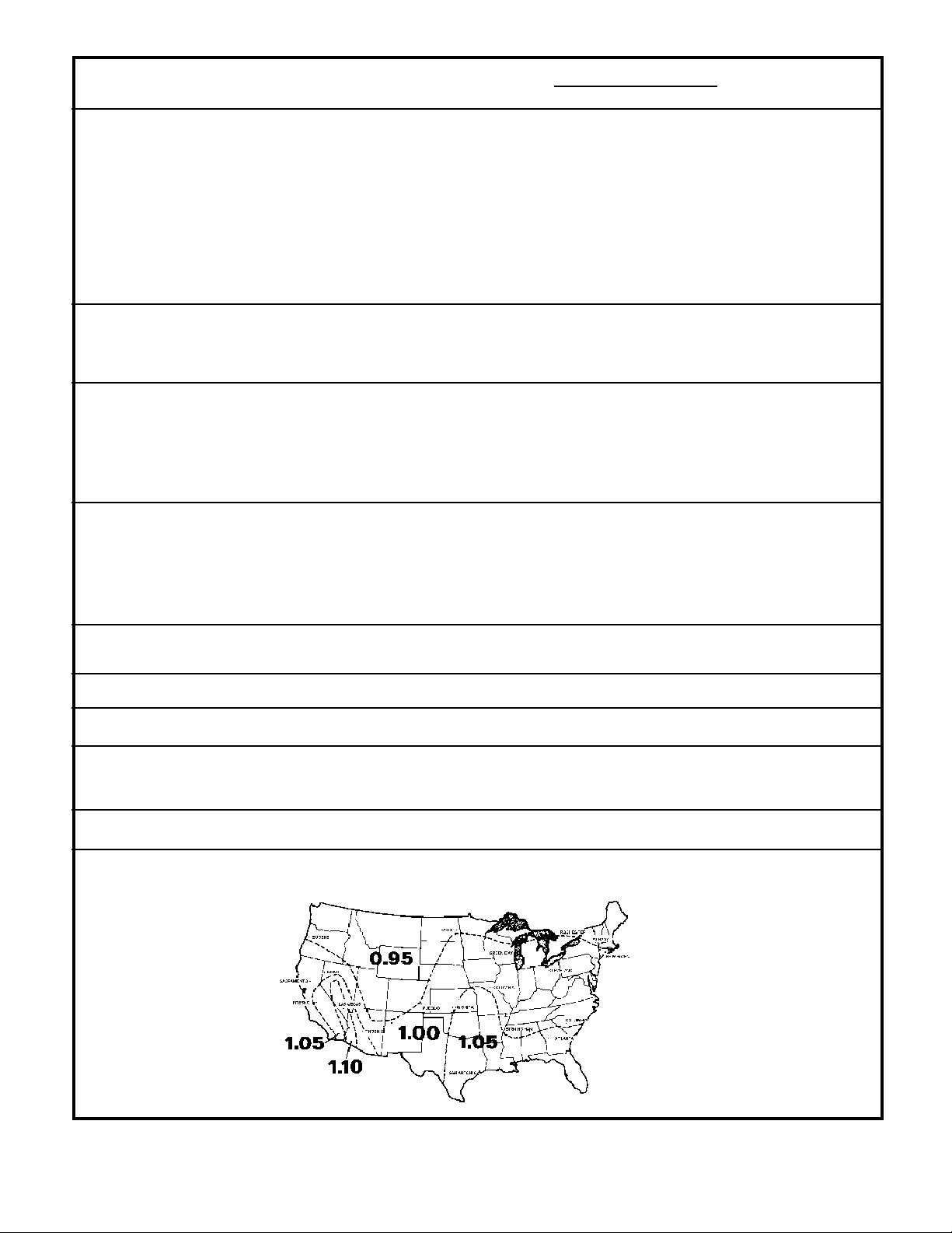
Cooling load requirements are generally based on the cooling load for comfortable air conditioning which does not
require specific conditions of inside temperature and humidity. The load calculation form is based on outside
design temperature of 95° FDB and 75° FWB. It can be used for areas in the Continental United States having
other outside design temperatures by applying a correction factor for the particular locality as determined from the
map shown on Page 6.
When sizing a TwinTemp unit for cooling and heating, we must remember that the heating capacity of any given
unit varies directly with the outdoor ambient temperature. Also, we must keep in mind the average low temperatures which might be experienced in the locality where the unit is to be installed. Theref ore, when sizing a T winTemp
unit, both cooling and heating requirements must be calculated. Do not oversize, or undersize, one phase of the
unit’s capacity at the expense of the other. In those cases where the unit will provide satisfactory cooling at all
times but will be inadequate for those few times that the outdoor temperature is below the maximum low for the
unit, additional auxiliary heating facilities must be provided to insure that adequate heat is available at all times.
5

INSTRUCTIONS FOR USING COOLING LOAD ESTIMATE
FORM FOR ROOM AIR CONDITIONERS
(AHAM PUB. NO. RAC-1)
A. This cooling load estimate form is suitable for estimating the cooling load for comfort air conditioning installations
which do not require specific conditions of inside temperature and humidity.
B. The form is based on an outside design temperature of 95°F dry bulb and 75°F wet bulb. It can be used for areas
in the continental United States having other outside design temperatures by applying a correction factor for the
particular locality as determined from the map.
C. The form includes "day" factors for calculating cooling loads in rooms where da ytime comfort is desired (such as
living rooms, offices, etc.)
D . The numbers of the following paragraphs refer to the corresponding numbered item on the f orm:
1. Multiply the square feet of window area f or each exposure b y the applicab le factor. The window area is the
area of the wall opening in which the window is installed. For windows shaded b y inside shades or venetian
blinds, use the factor for "Inside Shades." For windows shaded by outside awnings or by both outside
awnings and inside shades (or venetian blinds), use the factor for "Outside Awnings." "Single Glass"
includes all types of single thickness windows, and "Doub le Glass" includes sealed airspace types, storm
windows, and glass b lock. Only one n umber should be entered in the right hand column for Item 1, and this
number should represent only the exposure with the largest load.
2. Multiply the total square feet of all windows in the room b y the applicable factor.
3a. Multiply the total length (linear feet) of all walls e xposed to the outside by the applicab le factor . Doors should
be considered as being part of the wall . Outside walls facing due north should be calculated separately
from outside walls facing other directions. Walls which are permanently shaded by adjacent structures
should be considered “North Exposure.” Do not consider trees and shrubbery as providing permanent
shading. An uninsulated frame wall or a masonry wall 8 inches or less in thickness is considered "Light
Construction." An insulated wall or masonry wall over 8 inches in thickness is considered "Heavy Construction."
3b. Multiply the total length (linear feet) of all inside walls betw een the space to be conditioned and any uncon-
ditioned spaces by the given f actor . Do not include inside walls which separate other air conditioned rooms.
4. Multiply the total square feet of roof or ceiling area by the factor given for the type of construction most
nearly describing the particular application (use one line only.)
5. Multiply the total square feet of floor area by the factor giv en. Disregard this item if the floor is directly on the
ground or over a basement.
6. Multiply the number of people who normally occupy the space to be air conditioned by the f actor given. Use
a minimum of 2 people.
7. Determine the total number of watts f or light and electrical equipment, except the air conditioner itself , that
will be in use when the room air conditioning is operating. Multiply the total wattage by the factor given.
8. Multiply the total width (linear feet) of any doors or arches which are continually open to an unconditioned
space by the applicable factor.
NOTE: Where the width of the doors or arches is more than 5 feet, the actual load may exceed the
calculated value . In such cases , both adjoining rooms should be considered as a single large room, and the
room air conditioner unit or units should be selected according to a calculation made on this new basis.
9. T otal the loads estimated for the foregoing 8 items.
10. Multiply the subtotal obtained in item 9 by the proper correction factor, selected from the map, for the
particular locality. The result is the total estimated design cooling load in BTU per hour.
E. For best results, a room air conditioner unit or units having a cooling capacity r ating (determined in accordance
with the NEMA Standards Publication for Room Air Conditioners, CN 1-1960) as close as possible to the estimated load should be selected. In general, a greatly oversized unit which would operate intermittently will be
much less satisfactory than one which is slightly undersized and which w ould operate more nearly continuously.
F. Intermittent loads such as kitchen and laundry equipment are not included in this form.
6
COOLING LOAD ESTIMATE FORM
HEAT GAIN FROM
1. WINDOWS: Heat gain from the sun.
Northeast
East
Southeast
South
Southwest
West
Northwest
North
2. WINDOWS: Heat by conduction
(Total of all windows.)
Single glass
Double glass or glass block
3. WALLS: (Based on linear feet of wall)
a. Outside walls
North Exposure
Other than North exposure
b. Inside Walls (between conditioned and
unconditioned spaces only.)
4. ROOF OR CEILING: (Use one only)
a. Roof, uninsulated
b. Roof, 1 inch or more insulation
c. Ceiling, occupied space above
d. Ceiling, insulated, with attic space above
e. Ceiling, uninsulated, with attic space above
* These factors are for single glass
only. For glass block, multiply the
above factors by 0.5; for double glass
or storm windows, multiply the above
factors by 0.8.
QUANTITY
____sq. ft.
____sq. ft.
____sq. ft.
____sq. ft.
____sq. ft.
____sq. ft.
____sq. ft.
____sq. ft.
____sq. ft.
____sq. ft.
____ ft.
____ ft.
____sq. ft.
____sq. ft.
____sq. ft.
____sq. ft.
____sq. ft.
____sq. ft.
FACTORS
DAY
No
Shades*
60
80
75
75
110
150
120
0
Light Construction
30
60
Inside
Shades*
Outside
Awnings*
25
40
30
35
45
65
50
0
14
30
19
12
20 ____
25 ____
20 ____
20 ____
30 ____
45 ____
35 ____
0 ____
7
Heavy Construction
8
3
5
BTU/Hr.
(Quantity x Factor)
(Area
X Factor)
____
Use
____
only
____
the
Use
only
one.
____
____
____
____
____
_____
_____
_____
_____
_____
_____
_____
_____
_____
_____
largest
load.
20
30
5. Floor: (Disregard if floor is directly on ground or over
a basement.
6. NUMBER OF PEOPLE
7. LIGHTS AND ELECTRICAL EQUIPMENT IN USE
8. DOORS AND ARCHES CONTINUOUSLY OPENED
TO UNCONDITIONED SPACE: (TOTAL LINEAR
FEET OF WIDTH.)
9. SUBTOTAL
10. TOTAL COOLING LOAD (BTU per hour to be used
for selection of room air conditioner(s).)
____ Total in Item 9 X ____(Factor from Map) = _______
____sq. ft.
____
____watts
____ft.
*****
3
600
3
300
*****
_____
_____
_____
_____
_____
7

HEAT LOAD FORM
The heat load form, Page 8, may be used by servicing
personnel to determine the heat loss of a conditioned
space and the ambient winter design temperatures in
which the unit will heat the calculated space.
The upper half of the form is for computing the heat loss
of the space to be conditioned. It is necessary only to
insert the proper measurements on the lines provided
and multiply by the given factors, then add this result for
the total heat loss in BTU/Hr./°F.
The BTU/Hr. per °F temperature difference is the 70°F
inside winter designed temperature minus the lowest
outdoor ambient winter temperature of the area where
the unit is installed. This temperature difference is used
as the multiplier when calculating the heat loss.
The graph shows the following:
Left Hand Scale Unit capacity BTU/Hr . or heat loss
BTU/Hr.
Bottom Scale Outdoor ambient temperature,
base point.
Heat Pump Model BTU/Hr. capacity heat pump will
deliver at outdoor temperatures.
Balance Point Maximum BTU/Hr . heat pump will
deliver at indicated ambient
temperature.
Below is an example using the heat load form:
A space to be conditioned is part of a house
geographically located in an area where the lowest
outdoor ambient winter temperature is 40°F. The
calculated heat loss is 184 BTU/Hr./°F.
Subtract 40°F (lowest outdoor ambient temperature for
the geographical location) from 70°F (inside design
temperature of the unit) for a difference of 30°F . Multiply
184 by 30 for a 5500 BTU/Hr. total heat loss for the
calculated space.
On the graph, plot the base point (70°) and a point on the
40°F line where it intersects with the 5500 BTU/Hr. line
on the left scale. Dr aw a straight line from the base
point 70 through the point plotted at 40°F. This is the
total heat loss line.
Knowing that we ha ve a 5500 BTU/Hr. heat loss, and we
expect that our heat pump will maintain a 70°F inside
temperature at 40°F outdoor ambient, we plot the selected
unit capacity BTU/Hr. of the unit between 35° and 60° on
the graph and dr aw a straight line betw een these points .
Where the total heat loss line and the unit capacity line
intersect, read down to the outdoor ambient temperature
scale and find that this unit will deliver the required BTU/
Hr. capacity to approximately 30°F.
8

HEATING LOAD FORM
FRIEDRICH ROOM UNIT HEAT PUMPS
BTU/HR PER
WALLS:(Linear Feet) °F TEMP. DIFFERENCE
2" Insulation Lin. Ft. x 1.6
Average Lin. Ft. x 2.6
WINDOWS & DOORS (Area, sq. ft.)
Single Glass: Sq. Ft. x 1.13
Double Glass: Sq. Ft. x 0.61
INFILTRATION - WINDOWS & DOORS: A VG. Lin. Ft. x 1.0
Loose Lin. Ft. x 2.0
CEILING: (Area, Sq. Ft.)
Insulated (6") Sq. Ft. x 0.07
Insulated (2") Sq. Ft. x 0.10
Built-up Roof (2" insulated Sq. Ft. x 0.10
Built-up Roof (1/2" insulated) Sq. Ft. x 0.20
No Insulation Sq. Ft. x 0.33
FLOOR: (Area, Sq. Ft.)
Above Vented Crawl space
Insulated (1:) Sq. Ft. x 0.20
Uninsulated Sq. Ft. x 0.50
* Slab on Ground Lin. Ft. x 1.70
1" Perimeter insulation Lin. Ft. x 1.00
* Based on Linear Feet of outside wall TOTAL HEA T LOSS PER °F BTU/HR/°F
Multiply total BTU/HR/°F X 30 and plot on the graph below at 40°F. Draw a straight line from
the 70 base point thru the point plotted at 40°F. The intersection of this heat loss line with the
unit capacity line represents the winter design heating load.
9
SPECIFICATIONS WS07A10D WS10A10B WS12A10E-B WS12A30EB WS15A30B
BTUH 7400 10000 11500 12000 14700
11800 14500
E.E.R. 9.5 9.2 9.2 9.0 8.7
9.0 8.5
Volts 115 115 115 230 230
208 208
Amperes 7.0 9.8 11.5 6.0 7.7
6.5 8.5
T otal Watts 773 1081 1280 1333 1693
1310 1686
Hertz 60 60606060
Fuse/Breaker Size 15 15 15 15 15
Fan RPM 1145 1140 1275 1275 1275
Evaporator Air CFM 260 260 290 290 250
Fresh Air CFM
Exhaust Air Ye s Yes Y es Y es Yes
Dehumidification Pts/Hr 1.4 2.1 2.9 2.9 4.0
Width 27" 27" 27" 27 " 27"
Height 16-3/4" 16-3/4" 16-3/4" 16-3/4" 16-3/4"
Depth 16-3/4" 16-3/4" 16-3/4" 16-3/4" 16-3/4"
Minimum Ext. Into Room 7-1/2" 7-1/2" 7-1/2" 7-1/2" 7-1/2"
Minimum Ext. To Outside 9/16" 9/16" 9/16" 9 /16 " 9/16"
Net Weight 75 85 94 91 101
Shipping Weight 93 103 112 109 119
PERFORMANCE
DATA*
Cooling
WS07A10D 59.5 19.5 82 280 7.0 32.0 19 11.8
WS09A10D 58.0 22.0 82 295 9.8 44.0 20 11.8
WS12A10D 55.0 25.0 76 295 11.5 54.0 36 11.8
WS12A30D 55.0 25.0 76 295 6.0 26.3 36 11.8
WS13A30D 47.1 32.9 73 308 7.7 33.0 38 11.8
*Rating Conditions: 80°F. Room Air Temperature and 50% Relative Humidity with
EVAPORATOR AIR OPERATING ELECTRICAL R-22 COMP.
TEMP. °F. PRESSURES RATINGS REFRIG. O IL
DISCHARGE TEMP. SUCTION DISCHARGE AMPS LOCKED CHARGE IN CHARGE IN
AIR DROP °F. ROTOR AMPS OUNCES FLUID OZ.
6.5
8.5
95°F. Outside Air Temper ature at 40% Relative Humidity.
10
SPECIFICATIONS W E0 7 A 3 3E C WE1 2 A3 3 E B WE15A33B WY09A33FA WY1 2 A 33 G A
BTUH (Cooling) 9000 12000 14700 9000 11500
8900 11800 14500 8900 11000
BTUH (Heating) 7000 11000 11000 7000 10500
7000 9100 9100 7000 10300
E.E.R. (Cooling) 8.7 9.0 8.7 8.6 9.0
9.0 8.6 9.3 9.0
E.E.R (Heating) 8.7 8.7 9.0
8.7 9.0
Volts 230 230 230 230 230
208 208 208 208 208
Amperes (Cooling) 4.3 6.0 7.7 3.6 5.8
4.6 6.5 8.5 4.0 6.2
Amperes (Heating) 16.0 16.0 16.93 16.7 16.0
14.7 14.7 16.86 14.7 14.7
Total Watts (Cooling) 973 1333 1693 973 1307
947 1310 1686 947 1273
Total Watts (Heating) 805 3550 3550 805 1167
805 2950 2950 805 1144
Hertz 6060606060
Fuse/Breaker Size 20 20 20 20 20
Fan RPM 1140 1275 1275 1140 1275
Evaporator Air CFM 260 290 250 27 0 290
Fresh Air CFM
Exhaust Air CFM Yes Yes Y e s Yes Yes
Dehumidification Pts/Hr 2.1 2.9 4.0 2.1 2.9
Width 27" 27" 27" 27" 27"
Height 16 3/4" 16 3/4" 16 3/4" 16 3/4" 16 3/4"
Depth 16 3/4" 16 3/4" 16 3/4" 16 3/4" 16 3/4"
Minimum Ext. Into Room 7 1/2" 7 1/2" 7 1/2" 7 1/2" 7 1/2"
Minimum Ext. To Outside 9/16" 9/16" 9/16" 9/16" 9/16"
Net Weight 84 92 102 86 94
Shipping Weight 103 111 121 107 116
PERFORMANCE
DATA*
Cooling
EVAPORATOR AIR OPERATING ELECTRICAL R-22 COMP.
TEMP. °F. PRESSURES RATINGS REFRIG. OIL
DISCHARGE TEMP. SUCTION DISCHARGE AMPS LOCKED CHARGE IN CHARGE IN
AIR DROP °F. ROTOR AMPS OUNCES FLUID OZ.
WE09A33EC 58.0 22.0 80 295 4.3 20.0 20 11.8
4.6
WE12A33EB 55.0 25.0 76 295 6.0 26.3 36 11.8
6.5
WE15A33B 47.1 32.9 73 308 7.7 33.0 38 11.8
8.5
WY09A33FA 58.0 22.0 80 295 3.6 20.0 26 11.8
5.8
WY12A33GA 55.0 25.0 76 295 5.8 26.3 43 11.8
6.2
*Rating Conditions: 80°F. Room Air Temperature and 50% Relative Humidity with
PERFORMANCE VOLTS BTUH CFM HEAT RISE
DATA (Heating) HIGH SPEED
95°F. Outside Air Temperature at 40% Relative Humidity.
WE09A33EC 230 11000 260 39.0
208 9100
WE12A33E-B 230 11000 290 35.0
208 9100
WE15A33GA 230 11000 250 40.0
208 9100
11
PERFORMANCE DATA *WY09A33FA *WY12A33GA
(Heating)
BTUH @70°F Inside 62°F Outside 9700 12400
@70°F Inside 57°F Outside 9300 12000
@70°F Inside 52°F Outside 8800 11400
** @70°F Inside 47°F Outside 8200/8100 10800/10400
@70°F Inside 42°F Outside 7600 10000
@70°F Inside 37°F Outside 6800 9000
@70°F Inside 35°F Outside 11000/9100 11000/9100
Evaporator Air T emperature Rise
@70°F Inside 62°F Outside 32.00 37.60
@70°F Inside 57°F Outside 30.75 36.40
@70°F Inside 52°F Outside 29.10 34.50
** @70°F Inside 47°F Outside 27.10/26.80 32.70/31.50
@70°F Inside 42°F Outside 25.10 30.30
@70°F Inside 37°F Outside 22.50 27.30
@70°F Inside 35°F Outside 36.40/30.10 33.30/27.60
AMPS @70°F Inside 62°F Outside 4.0 5.6
@70°F Inside 57°F Outside 3.9 5.5
@70°F Inside 52°F Outside 3.85 5.4
** @70°F Inside 47°F Outside 3.8/4.1 5.3/5.6
@70°F Inside 42°F Outside 3.6 5.1
@70°F Inside 37°F Outside 3.4 4.8
@70°F Inside 35°F Outside 16.0/14.7 16.0/14.7
Watt s @70°F Inside 62°F Outside 880 1280
@70°F Inside 57°F Outside 870 1260
@70°F Inside 52°F Outside 860 1220
** @70°F Inside 47°F Outside 835/810 1175/1155
@70°F Inside 42°F Outside 800 1130
@70°F Inside 37°F Outside 760 1070
@70°F Inside 35°F Outside 3550/2950 3550/2950
Suction/Head PSIG
@70°F Inside 62°F Outside 66/315 61/325
@70°F Inside 57°F Outside 62/285 59/290
@70°F Inside 52°F Outside 57/285 53/275
** @70°F Inside 47°F Outside 53/265 49/255
@70°F Inside 42°F Outside 49/215 45/240
@70°F Inside 37°F Outside 45/203 41/220
@70°F Inside 35°F Outside 44/200 40/215
* Heating Element comes on at 35°F outside ambient and compressor shuts off.
** AHAM Rating Conditions.
12
COMPONENTS OPERATION & TESTING
WARNING
DISCONNECT ELECTRICAL POWER TO
UNIT BEFORE SERVICING OR TESTING
COMPRESSORS
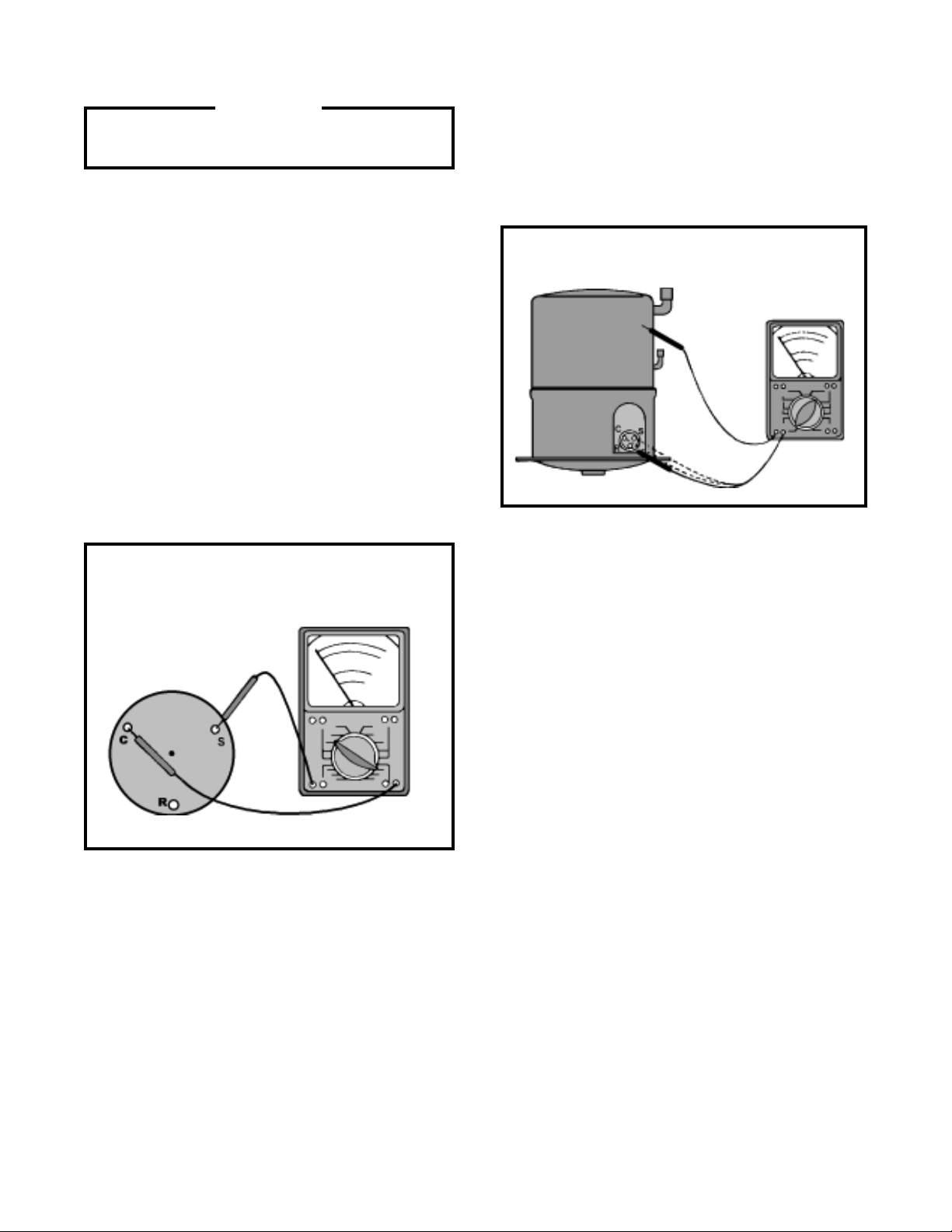
GROUND TEST
Use an ohmmeter set on its highest scale. Touch one
lead to the compressor body (clean point of contact as
a good connection is a must) and the other probe in
turn to each compressor terminal (see Figure 2.) If a
reading is obtained, the compressor is grounded and
must be replaced.
Compressors are single phase, 115 or 230/208 volt, depending on the model unit. All compressor motors are
permanent split capacitor type using only a running capacitor across the start and run terminal.
All compressors are internally spring mounted and externally mounted on rubber isolators.
COMPRESSOR WINDING TEST
Remove compressor terminal box cover and disconnect
wires from terminals. Using an ohmmeter, check continuity across the following:
(See Figure 1)
Figure 1: Compressor Winding Test
Figure 2: Typical Ground Test
CHECKING COMPRESSOR EFFICIENCY
The reason for compressor inefficiency is normally due
to broken or damaged suction and/or discharge v alves ,
reducing the ability of the compressor to pump refrigerant gas.
This condition can be checked as follows:
1. Install a piercing valve on the suction and discharge or liquid process tube.
1. Terminal “C” and “S” - no continuity - open winding - replace compressor.
2. Terminal “C” and “R” - no continuity - open winding - replace compressor.
3. Terminal “R” and “S” - no continuity - open winding - replace compressor.
2. Attach gauges to the high and low sides of the
system.
3. Start the system and run a “cooling or heating
perf ormance test.”
If test shows:
A. Below normal high side pressure.
B. Above normal low side pressure.
C. Low temperature difference across coil.
The compressor valves are faulty - replace the
compressor.
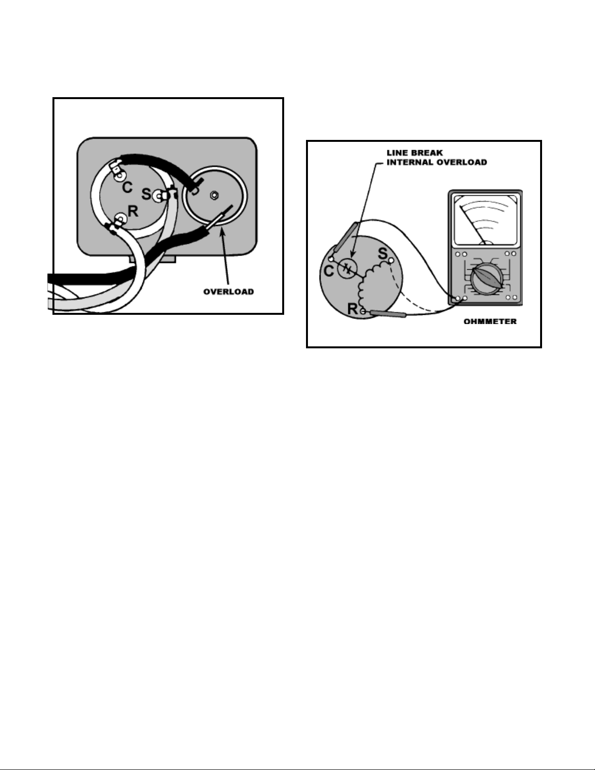
THERMAL OVERLOAD (External)
Some compressors are equipped with an e xternal overload which is located in the compressor terminal box
adjacent to the compressor body (see Figure 3.)
13
The overload is wired in series with the common motor
terminal. The overload senses both major amper age and
compressor temperature. High motor temperature or
amperage heats the disc causing it to open and break
the circuit to the common motor terminal.
Figure 3: External Overload
Should the internal temperature and/or current draw
become excessive, the contacts in the overload will open,
turning off the compressor . The ov erload will automatically
reset, but may require several hours before the heat is
dissipated.
CHECKING THE INTERNAL OVERLOAD (see Figure
4.)
Figure 4
Heat generated within the compressor shell is usually
due to:
1. High amperage.
2. Low refrigerant charge.
3. Frequent recycling.
4. Dirty condenser.
TERMINAL OVERLOAD - TEST
(Compressor - External Type)
1. Remove overload.
2. Allow time for ov erload to reset before attempting
to test.
3. Apply ohmmeter probes to terminals on overload
wires. There should be continuity through the
overload.
TERMINAL OVERLOAD (Internal)
Some model compressors are equipped with an internal
over load. The overload is embedded in the motor
windings to sense the winding temperature and/or
current draw. The overload is connected in series with
the common motor terminal.
1. With no power to unit, remove the leads from the
compressor terminals.
2. Using an ohmmeter, test continuity between
terminals C-S and C-R. If not continuous, the
compressor overload is open and the compressor
must be replaced.
F AN MOTOR
A single phase permanent split capacitor motor is used
to drive the evaporator b lower and condenser fan. A selfresetting overload is located inside the motor to protect
against high temperature and high amperage conditions.
Although fan motors are lubricated at the factor y and
sealed, oil ports are provided to lubricate to motor annually
after the first year of operation (see Figure 5.) To lubricate
(oil), remove the oil plugs on each end of the fan motor
and put up to 30 drops of SAE10W30 grade motor oil in
each hole, then replace oil plugs.
14
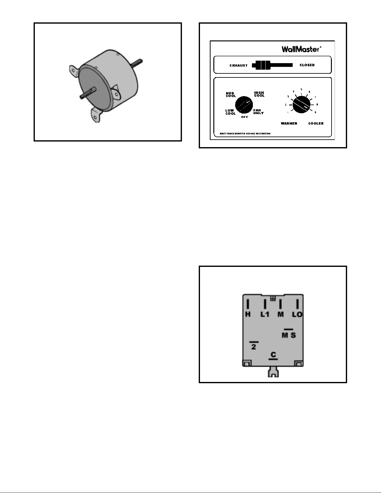
Figure 5: F an Motor
Figure 6: System Control Panel
F AN MOTOR - TEST
1. Determine that capacitor is serviceable.
2. Disconnect fan motor wires from fan speed s witch
or system switch.
3. Apply “live” test cord probes on bl ack wire and
common terminal of capacitor. Motor should run
at high speed.
4. Apply “live” test cord probes on red wire and
common terminal of capacitor. Motor should run
at low speed.
5. Apply “live” test cord probes on each of the
remaining wires from the speed switch or system
switch to test intermediate speeds.
SYSTEM CONTROL SWITCH ("WS" Models)
A five position control switch is used to regulate the
operation of the fan motor and compressor. The
compressor can be operated with the fan operating at
low, medium or high speed. The fan motor can also be
operated independently on medium speed. See switch
section as indicated on decorative control panel (see
Figure 7.)
1. “Off” Position - no continuity between terminals.
2. “Lo Cool” Position - between terminals “L1” and “C”,
“LO” and “MS”.
3. “Med Cool” Position - between terminals “L1” and
“C”, “M” and “MS”.
4. “Hi Cool” Position - between terminals “L1” and “C”,
“H” and “MS”.
5. “Fan Only” Position - between terminals “L1” and
Figure 7: System Control Switch
SYSTEM CONTROL SWITCH - TEST
Disconnect leads from control switch (see Figure 8.)
There must be continuity as follows:
SYSTEM CONTROL SWITCH
("WE" & "WY" Models)
An eight position switch is used to regulate the operation of the fan motor, compressor and electric heater.
15
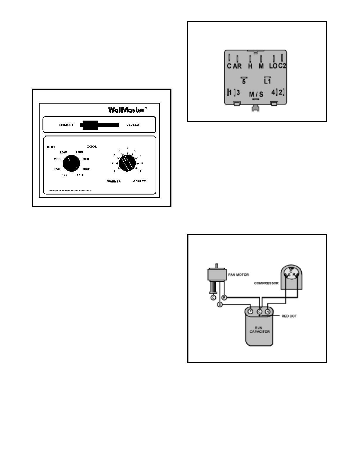
The unit can be operated in cooling or heating mode
with the compressor or electric heater on and the fan
motor operating on low , medium or high speed.
The fan motor can also be operated independently on
medium speed. See s witch section as indicated on decorative control panel, in Figure 8.
Figure 8: System Control Panel
Figure 9: System Control Switch
(Heat Pump & Electric Heat Models)
“2”.
NOTE:
Units will operate in constant fan in the cooling mode and auto fan in the heating mode.
CAPACITOR, RUN
SYSTEM CONTROL SWITCH - TEST
Disconnect leads from control switch. Turn control to
position being tested (see Figure 8.) There must be continuity as follows:
1. "Off" Position-no contin uity between terminals.
2. "Lo Cool" Position-between terminals "C" and "3",
"C2" and "2", "LO" and "M/S", "AR" and "5".
3. "Med Cool" Position-between terminals "C" and
"3", "C2" and "2", "M" and "M/S", "AR" and "5".
4. "Hi Cool" Position-between terminals "C" and "3",
"C2" and "2", "H" and "M/S", "AR" and "5".
5. "Hi Heat" Position-betw een terminals "C" and "1",
"C2" and "4", "H" and "M/S", "AR" and "5".
6. "Med Heat" Position-between terminals "C" and
"1", "C2" and "4", "M" and "M/S", "AR" and "5".
7. "Lo Cool" Position-between terminals "C" and "1",
"C2" and "4", "LO" and "M/S", "AR" and "5".
8. "Fan Only" Position-between terminals "L1" and
"M".
A run capacitor is wired across the auxiliary and main
winding of a single phase permanent split capacitor motor such as the compressor and fan motor. A single capacitor can be used for each motor or a dual rated capacitor can be used for both.
Figure 10: Run Capacitor Hook-Up
The capacitor’s primar y function is to reduce the line
current while greatly improving the torque characteristics of a motor. The capacitor also reduces the line current to the motor by improving the power factor of the
load. The line side of the capacitor is marked with a red
dot and is wired to the line side of the circuit (see Figure
10.)
16

CAPACITOR - TEST
1. Remove capacitor from unit.
2. Check for visual damage such as bulges, cracks,
or leaks.
3. For dual rated, apply an ohmmeter lead to common (C) terminal and the other probe to the compressor (HERM) terminal. A satisfactory capacitor
will cause a deflection on the pointer, then gradually move b ack to infinity.
4. R everse the leads of the probe and momentarily
touch the capacitor terminals. The deflection of the
pointer should be two times that of the first check if
the capacitor is good.
5. Repeat steps 3 and 4 to check fan motor capacitor.
NOTE: A shorted capacitor will indicate a low resis-
tance and the pointer will move to the “0” end of
the scale and remain there as long as the probes
are connected.
Figure 11: Thermostat
An open capacitor will show no movement of the
pointer when placed across the terminals of the
capacitor.
THERMOSTAT
("WS" Models)
Thermostat part number 613-503--10 (see Figure 11)
is used to cycle the unit "on" and "off" at the comfort
lev el desired.
The thermostat has a range from 60° F ±2° to 90° F
±5°, with a differential of 5½° F. T urning the control knob
clockwise lowers the indoor temperature setting, while
turning the control knob counterclockwise raises the indoor temperature setting. The comfor t range as listed
on the control panel is numbered from 1 through 9 (see
Figure 6.)
TEST:
Remove wires from thermost at. Turn thermostat to its
coldest position. Check to see if there is continuity between the two terminals. T urn the thermostat to its warmest position. Check continuity to see if thermostat contacts open. NOTE: Temperature must be within range
listed to check thermostat. Refer to troubleshooting section in this manual f or additional inf ormation on thermostat testing.
THERMOSTAT
("WE" & "WY" Models)
Figure 12: Thermostat
A cross ambient thermostat, part number 608-950-04
(see Figure 12) is used on all electric heat and heat
pump WallMaster models.
Range from 63° F (±2° F) to 98° F (±2° F).
17

TEST:
Remove wires from thermostat and check continuity
between terminal "2" (common) and "1" for heating. Also
check that contacts in thermostat open after placing in
either position. NOTE: Temperature must be within range
listed to check thermostat.
THERMOST AT ADJUSTMENT
Should the fan motor fail or filter become clogged, the
high limit control will open and interrupt power to the
heater before reaching an unsafe temperature condition.
The control is designed to open at 120° F ± 5° F. Test
continuity below 120° F and for open above 120° F.
DEFROST THERMOST AT
("WY" Models Only)
No attempt should be made to adjust thermostat. Due
to the sensitivity of the internal mechanism and the sophisticated equipment required to check the calibration,
it is suggested that the thermostat be replaced rather
than calibrated.
HEA TING ELEMENT
("WE" &"WY" Models)
All "WE" and "WY" models are equipped with a 3.3 KW
heating element.
The heating element contains a fuse link and heater limit
switch. The fuse link is in series with the power supply
and will open and interrupt the power when the temperature reaches 183° F, or a short circuit occurs in the
heating element. Once the fuse link separates, a new
fuse link must be installed. NOTE: Always replace with
the exact replacement.
The heater element has a high limit control. This control
is a bi-metal thermostat mounted in the top of the heating element.
This thermostat is a single pole - double throw with contacts between terminal "2" and "3" closing on temperature rise and contacts between terminals "2" and "1"
closing on temperature fall . When the contacts between
terminals "2" and "3" open, power to the compressor is
interrupted. When contacts between terminals "2" and
"1" make, pow er is suppled to the heater element.
This control is a dual purpose control that acts as an
outdoor thermostat and defrost control.
When the sensing bulb, attached to the condenser coil,
senses enough icing on the outdoor coil it will interrupt
power to the compressor and supply power to the heating element until the coil temperature reaches above
43°. Then the heater will shut off and the unit will resume operating in the reverse cycle mode.
When the outdoor coil temperature drops below 20 degrees, the unit will operate in electric heat mode continuously until the outdoor coil temperature rises above
43°.
Figure 13: Heating Element
18
Figure 14: Defrost Control

DEFROST BULB LOCATION
CHECK V AL VE: LIQUID DRY ER
(All "WY" Models)
The defrost control bulb must be mounted securely and
in the correct location to operate properly (see Figure
15.)
Figure 15: Defrost Bulb Location
(All "WY" Models)
OPERATION HEAT PUMP
COOLING MODE (See Figure 16)
In the cooling mode of operation, liquid refrigerant from
condenser (liquid line) enters the cooling check valve
forcing the heating check v alve shut. The liquid refrigerant is directed into the liquid dryer after which the refrigerant is metered through cooling capillary tubes to
evapor ator. (Note: liquid refrigerant will also be directed
through the heating capillary tubes in a continuous loop
during the cooling mode).
Figure 16
SOLENOID COIL
("WY" Models Only)
The solenoid coil is an electromagnetic type coil mounted
on the reversing valve and is energized during the operation of the compressor in the heating cycle.
Should the reversing valve fail to shift during the heating cycle, test the solenoid coil. Also, ref er to T ouch T est
Chart on Page 24.
TO TEST:
1. Disconnect power to unit.
2. Disconnect coil leads.
3. Attach probes of an ohmmeter to each coil lead
and check f or continuity.
WARNING: Do not start unit with solenoid coil re-
moved from v alve, or do not remov e cord
after unit is in operation. This will cause
the coil to burn out.
HEATING MODE (see Figure 17)
In the heating mode of operation, liquid refrigerant from
the indoor coil enters the heating check valve forcing
the cooling check valve shut. The liquid refrigerant is
directed into the liquid dryer after which the refrigerant
is metered through the heating capillary tubes to outdoor coils. (Note: liquid refrigerant will also be directed
through the cooling capillary tubes in a continuous loop
during the heating mode).
Figure 17
19

V ALVE, DRAIN PAN (See Figure 18)
During the cooling mode of operation, condensate which
collects in the drain pan is picked up by the condenser
fan b lade and spra yed onto the condenser coil. This assists in cooling the refrigerant plus evaporating the water.
During the heating mode of operation, it is necessary
that water be removed to pre vent it from freezing during
cold outside temperatures. This could cause the condenser fan blade to freeze in the accumulated water
and prevent it from turning.
To provide a means of draining this water, a bellows
type drain valv e is installed over a drain opening in the
base pan. This valve is temperature sensitive and will
open when the outside temperature reaches 40° F. Th e
valve will close g radually as the temperature rises above
40° F to fully close at 60° F.
Figure 18: Drain Pan Valve
The pivot valv e is responsible for directing the refrigerant flow to the indoor or outdoor coil. There are three
small tubes connected to the pivot valv e body. The center pilot tube is the common pilot tube and is connected
to the center suction line. The outside tubes are connected to each end of the main valve body. The pilot
valve consists of a needle valve and spring. When the
solenoid is deenergized, the spring tension closes one
pilot port while the other remains open. When the solenoid is energized, the opposite end is closed. The piston in the main valve is pressure operated and will always travel in the direction of the open pilot tube port
which provides a path to the center tube . Pressure which
will increase in the opposite side of the valve will escape through a bleed port located in each piston. When
deenergized, the valv e will be in the cooling position.
Figure 19: Reversing Valve
REVERSING V AL VE
("WY" Models Only)
A reversing v alv e is used to change the refrigerant flow
within the system to permit heating or cooling (see Figure 19.)
The reversing v alve consists of a main v alve body which
houses the slide and piston, plus a pivot valv e which is
activated by a solenoid.
There are three tubes connected to one side of the main
valve body and one tube on the opposite side . The single
tube is connected to the compressor discharge line. The
center tube on the opposite side is the common suction
line to the compressor . The outside tubes are connected
to the indoor and outdoor coils.
TESTING REVERSING VALVE
Occasionally, the reversing valv e ma y stick in the heat-
ing or cooling position or in the mid-position.
When stuck in the mid-position, part of the discharge
gas from the compressor is directed back to the suction
side, resulting in excessively high suction pressure.
Check the operation of the v alv e by starting the system
and switching the operation from "Cooling" to "Heating"
and then back to "Cooling". Do not hammer on valve .
If valve fails to change its position, test the voltage to
the valv e coil while the system is in the heating cycle. If
voltage to the coil is satisf actory , replace reversing v alve.
Should the valve f ail to shift from cooling to heating, block
the air flow through the outdoor coil and allow the discharge pressure to build in the system. Then s witch the
system from cooling to heating.
20

If the valv e is stuck in the heating position, b loc k the air
flow through the indoor coil and allow discharge pressure to build in the system. Then switch the system from
heating to cooling.
Should the valve fail to shift in either position after increasing the discharge pressure, replace the valve .
NOTE: When brazing a reversing valve into the sys-
tem, it is of extreme importance that the temperature of the valve does not exceed 250° F at
any time .
Wrap the re versing valv e with a large rag saturated with water . "Re wet" the rag and thoroughly
cool the valve after each brazing operation of
the four joints involv ed.
The wet rag around the rev ersing valve will eliminate conduction of heat to the valve body when
brazing the line connection.
SEALED REFRIGERATION SYSTEM REP AIRS
EQUIPMENT REQUIRED
3. Accurately weighing the refrigerant charge actually introduced into the system.
4. Facilities f or flowing nitrogen through refrigeration
tubing during all brazing processes.
HERMETIC COMPONENT REPLACEMENT
The following procedure applies when replacing components in the sealed refrigeration circuit or repairin g
refrigerant leaks. (Compressor , condenser, ev aporator,
capillary tube , refrigerant leaks, etc.)
1. Recover the refriger ant from the system at the
process tube located on the high side of the system by installing a line tap on the process tube.
Apply gauge from process tube to EP A appro ved
gauges from process tube to EPA approved recovery system. Recover CFCs in system to at
least 5%.
2. Cut the process tube below pinch off on the suc-
tion side of the compressor.
1. Voltmeter
2. Ammeter
3. Ohmmeter
4. Vacuum Pump (capable of 200 microns or less
vacuum.)
5. Acetylene Welder
6. Electronic Halogen Leak Detector (G.E. Type H-6
or equivalent.)
7. Accurate refriger ant charge measuring device such
as:
a. Balance Scales - 1/2 oz. accuracy
b. Charging Board - 1/2 oz. accuracy
8. High Pressure Gauge - (0 - 400 lbs.)
9. Low Pressure Gauge - (30 - 150 lbs. )
10. V acuum Gauge - (0 - 1000 microns)
EQUIPMENT MUST BE CAPABLE OF:
1. Evacuation from both the high side and low side of
the system simultaneously .
2. Introducing refrigerant charge into high side of the
system.
3. Connect the line from the nitrogen tank to the suction process tube.
4. Drift dry nitrogen through the system and unsolder the more distant connection first. (Filter drier ,
high side process tube, etc.)
5. Replace inoperative component, and always install a new filter drier. Drift dr y nitrogen through
the system when making these connections.
6. Pressurize system to 30 PSIG with proper refrigerant and boost refrigerant pressure to 150 PSIG
with dry nitrogen.
7. Leak test complete system with electric halogen
leak detector, correcting any leaks found.
8. Reduce the system to zero gauge pressure.
9. Connect vacuum pump to high side and low side
of system with deep vacuum hoses, or copper
tubing. (Do not use regular hoses.)
10. Evacuate system to maximum absolute holding
pressure of 200 microns or less. NOTE: This process can be speeded up by use of heat lamps, or
by breaking the vacuum with refrigerant or dry
nitrogen at 5,000 microns. Pressure system to 5
PSIG and leave in system a minimum of 10 minutes. Release refrigerant, and proceed with evacuation of a pressure of 200 microns or less.
21

11. Break vacuum by charging system from the high
side with the correct amount of refrigerant specified. This will pre vent boiling the oil out of the crankcase.
NOTE: If the entire charge will not enter the high
side, allow the remainder to enter the low side in
small increments while operating the unit.
12. Restart unit sever al times after allowing pressures
to stabilize. Pinch off process tubes, cut and solder the ends. Remove pinch off tool, and leak
check the process tube ends.
SPECIAL PROCEDURE IN THE CASE OF MOTOR
COMPRESSOR BURNOUT
1. Recover a ll re frigerant and oil from the system.
2. Remove compressor , capillary tube and filter drier
from the system.
3. Flush evaporator condenser and all connecting
tubing with dry nitrogen or equivalent, to remove
all contamination from system. Inspect suction and
discharge line for carbon deposits. Remove and
clean if necessary.
REFRIGERANT CHARGE
1. The refrigerant charge is e xtremely critical. Measure charge carefully - as exact as possible to the
nameplate charge.
2. The correct method for charging the rotary is to
introduce liquid refrigerant into the high side of
the system with the unit off. Then start compressor and enter the balance of the charge, gas only,
into the low side.
The introduction of liquid into the low side, without the use of a capillary tube, will cause damage
to the discharge valve of the rotary compressor.
NOTE: All inoperativ e compressors returned to
Friedrich must hav e all lines properly plugged with
the plugs from the replacement compressor.
4. Reassemble the system, including new drier
strainer and capillary tube.
5. Proceed with processing as outlined under hermetic component replacement.
ROTARY COMPRESSOR SPECIAL
TROUBLESHOO TING AND SERVICE
Basically , troubleshooting and servicing rotary compressors is the same as on the reciprocating compressor
with only a few e xceptions.
1. Because of the spinning motion of the rotary, the
mounts are critical. If vibration is present, check
the mounts carefully.
2. The electrical terminals on the rotary are in a different order than the reciprocating compressors .
The terminal markings are on the cover gasket.
Use your wiring diagram to insure correct connections.
22

TROUBLESHOOTING TOUCH TEST CHART
TO SERVICE REVERSING VALVES
NORMAL FUNCTION OF VALVE
VALVE
OPERATING
CONDITION
SUCTION TUBE
to Compressor
from Compressor
DISCHARGE TUBE
Tube to INSIDE
COIL
Tube to OUTSIDE
COIL
LEFT Pilot
Capillary Tube
RIGHT Pilot
* TEMPERATURE OF VALVE BODY
** WARMER THAN VALVE BODY
Capillary Tube
NOTES:
1 2 3 4 5 6 POSSIBLE CAUSES CORRECTIONS
Normal Hot Cool Cool, Hot, *TVB TVB
Cooling as(2) as (1)
Normal Heating Hot Cool Hot, Cool, *TVB TVB
as(1) as (2)
MALFUNCTION OF V ALVE
No voltage to coil.
Defective coil.
Low charge
Pressure differential too high.
Pilot valve okay. Dirt in one
Hot
bleeder hole.
Piston cup leak
Clogged pilot tubes.
Both ports of pilot open. (Back seat
port did not close).
Defective Compressor
Not enough pressure differential at
start of stroke or not enough flow to
maintain pressure differential.
Body damage
Both ports of pilot open.
Body damage
V alve hung up at mid-stroke. Pumping
volume of compressor not sufficient to
maintain reversal.
Both ports of pilot open.
Piston needle on end of slide leaking.
**
Pilot needle and piston needle leaking
Pressure differential too high
.
Clogged pilot tube.
Dirt in bleeder hole.
Valve will
not shift
from cool to
heat.
Valve will
not shift
from cool to
heat.
Starts to
shift but
does not
complete
reversal.
Apparent
leap in
heating.
Hot
Hot
Hot
Warm
Hot
Hot
Hot
Hot
Hot
Hot
Hot
Hot
Check Electrical circuit and coil
Check refrigeration charge
Cool
Cool
Cool
Cool
Warm
Warm
Hot
Hot
Cool
Cool
Cool
Cool
Cool,
as (2)
Cool,
as (2)
Cool,
as (2)
Cool,
as (2)
Warm
Warm
Hot
Hot,
Hot,
as (1)
Hot,
as (1)
Hot,
as (1)
Hot,
as (1)
Hot,
as (1)
Hot,
as (1)
Hot,
as (1)
Warm,
as (1)
Hot
Hot
Hot
Hot
Cool,
as (2)
Cool,
as (2)
Cool,
as (2)
Cool,
as (2)
*TVB
*TVB
Hot
*TVB
*TVB
Hot
*TVB
Hot
*TVB
**
WVB
*TVB
Hot
*TVB
Hot
Warm
Hot
Hot
Hot
Hot
*TVB
WVB
*TVB
*TVB
Will not shift
from heat to
cool.
Valve operated satisfactorily PRIOR to compressor motor burnout – caused by dirt and small greasy p articles inside the valve. TO CORRECT: Remove valve, thoroughly
wash it out. Check on air before reinstalling, or replace valve. Add strainer and filter-drier to discharge tube between valve and compressor.
Hot
Hot
Warm
Cool
Cool
Cool
Hot,
as (1)
Hot,
as (1)
Warm,
as (1)
Cool,
as (2)
Cool,
as (2)
Cool,
as (2)
Hot
Hot
Warm
*TVB
Hot
*TVB
Piston cup leak
Defective pilot.
Defective compressor.
Repair electrical circuit.
Replace coil.
Repair leak, recharge system.
Recheck system.
Deenergize solenoid, raise head pressure,
reenergize solenoid to break dirt loose. If
unsuccessful, remove valve, wash out. Check
on air before installing. If no movement, replace
valve, add strainer to discharge tube, mount
valve horizontally .
S top unit. After pressures equalize, restart with
solenoid energized. If valve shifts, reattempt
with compressor running. If still no shift, replace
valve.
Raise head pressure, operate solenoid to free.
If still no shift, replace valve.
Raise head pressure, operate solenoid to free
partially clogged port. If still no shift, replace
valve.
Check unit for correct operating pressures and
charge. Raise head pressure. If no shift, use
valve with smaller port.
Replace valve
Raise head pressure, operate solenoid. If no
shift, replace valve.
Replace valve
Raise head pressure, operate solenoid. If no
shift, use valve with smaller ports.
Raise head pressure, operate solenoid. If no
shift, replace valve.
Operate valve several times, then recheck. If
excessive leak, replace valve.
Operate valve several times, then recheck. If
excessive leak, replace valve.
Stop unit. W ill reverse during equalization
period. Recheck system
Raise head pressure, operate solenoid to free
dirt. If still no shift, replace valve.
Raise head pressure, operate solenoid.
Remove valve and wash out. Check on air
before reinstalling, if no movement, replace
valve. Add strainer to discharge tube. Mount
valve horizontally .
Stop unit. Af ter pressures equalize, restart with
solenoid deenergized. If valve shifts, reattempt
with compressor running. If it still will not reverse
while running, replace the valve.
Replace valve.
23

TROUBLESHOOTING COOLING
PROBLEM
Compressor does
not run.
PROBLEM
Fan motor
does not run.
POSSIBLE CAUSE
Low voltage.
Thermostat not set cold enough
or inoperative.
Compressor hums but cuts off on
overload.
Open or shorted compressor
windings.
Open overload.
Open capacitor.
Inoperative system switch.
Broken, loose or incorrect wiring.
POSSIBLE CAUSE
Inoperative system switch.
Broken, loose or incorrect wiring.
Open Capacitor .
Fan speed switch open.
Inoperative fan motor.
TO CORRECT
Check for voltage at compressor. 115 volt and 230
volt units will operate at 10% voltage variance
Set thermostat to coldest position. Test thermostat
and replace if inoperative.
Hard start compressor. Direct test compressor. If
compressor starts, add starting components.
Check for continuity and resistance.
Test overload protector and replace if inoperative.
Test capacitor and replace if inoperative.
Test for continuity in all positions. Replace if
inoperative.
Refer to appropriate wiring diagram to check wiring.
TO CORRECT
Test switch and replace in inoperative.
Refer to applicable wiring diagram.
Test capacitor and replace if inoperative.
Test switch and replace if inoperative.
Test fan motor and replace if inoperative.
(Be sure internal overload has had time to
reset.)
PROBLEM
Does not cool,
or cools only
slightly.
POSSIBLE CAUSE
Undersized unit.
Thermostat open or inoperative.
Dirty filter.
Dirty or plugged condenser or
evaporator coil.
Poor air circulation in area being
cooled.
Fresh air or exhaust air door open
on applicable models.
Low capacity – undercharge.
Compressor not pumping properly.
TO CORRECT
Refer to Sizing Charts.
Set to coldest position. Test thermostat and
replace if necessary.
Clean as recommended in Owner’s Manual.
Use steam or detergents to clean.
Adjust discharge air louvers. Use high fan
speed.
Close doors. Instruct customer on use of
this feature.
Check for leak and make repair.
Check amperage draw against nameplate.
If not conclusive, make pressure test.
24

PROBLEM
Unit
does
not run.
POSSIBLE CAUSE
Fuse blown or circuit tripped.
Power cord not plugged in.
System switch in “Off” position.
Inoperative system switch.
Loose or disconnected wiring at
switch or other components.
TO CORRECT
Replace fuse, reset breaker. If repeats,
check fuse or breaker size. Check for
shorts in unit wiring and components.
Set switch correctly .
Test for continuity in each switch position.
Check wiring and connections. Reconnect
per wiring diagram.
PROBLEM
Evaporator coil
freezes up.
PROBLEM
Compressor runs
continually.
Does not cycle
off.
POSSIBLE CAUSE
Dirty filter.
Restricted air flow.
Inoperative thermostat.
Short of refrigerant.
Inoperative fan motor.
Partially restricted capillary .
POSSIBLE CAUSE
Excessive heat load.
Restriction in line.
Refrigerant leak.
Thermostat contacts stuck
Thermostat incorrectly wired.
TO CORRECT
Clean as recommended in Owner’s Manual.
Check for dirty or obstructed coil - clean as
required.
Test for shorted thermostat or stuck cont acts.
De-ice coil and check for leak.
Test fan motor and replace if inoperative.
De-ice coil. Check temp. differential across coil.
Touch test coil return bends for same tempera-
ture. Test for low running current.
Turn to higher temperature setting to see if unit
cycles off.
Refer to appro priate wiring diagram.
Refer to Sizing Chart.
TO CORRECT:
Unit undersized. Test cooling performance of unit.
Replace with larger unit.
Check for partially iced coil. Check temperature
split across coil.
Check for oil at silver soldered connections.
Check for partially iced coil. Check split across
coil. Check for low running amperage.
Check operation of thermostat. Replace if contacts remain closed.
Refer to appropriate wiring diagram.
PROBLEM
Thermostat does
not turn unit off.
POSSIBLE CAUSE
Thermostat contacts stuck.
Thermostat set at coldest point.
Incorrect wiring.
Unit undersized for area to be cooled.
TO CORRECT:
Replace thermostat.
Turn to higher temperature setting to see if the
unit cycles off.
Refer to appropriate wiring diagram.
Refer to Sizing Chart.
25

PROBLEM
Compressor
attempts to start,
or runs for short
periods only.
Cycles on overload.
POSSIBLE CAUSE TO CORRECT
Overload inoperative. Opens too
soon.
Compressor attempts to start before
system pressures are equalized.
Low or fluctuating voltage.
Incorrect wiring.
Shorted or incorrect capacitor.
Restricted or low air flow through
condenser coil.
Compressor running abnormally hot.
Check operation of unit. Replace overload if
system operation is satisfactory .
Allow a minimum of two (2) minutes for pressures
to equalize before attempting to restart. Instruct
customer of waiting period.
Check voltage with unit operating. Check for
other appliances on circuit. Air conditioner should
be on separate circuit for proper voltage, and be
fused separately .
Refer to appropriate wiring diagram.
Check by substituting a known good capacitor of
correct rating.
Check for proper fan speed or blocked condenser.
Check for kinked discharge line or restricted
condenser. Check amperage.
PROBLEM
Thermostat does
not turn unit on.
PROBLEM
Noisy operation.
PROBLEM
Water leaks
into room.
POSSIBLE CAUSE
Loss of charge in thermostat bulb.
Loose or broken parts in thermostat.
Incorrect wiring.
POSSIBLE CAUSE
Poorly installed unit.
Fan blade striking chassis.
Compressor vibrating.
Improperly mounted or loose cabinet
parts.
POSSIBLE CAUSE
Evaporator drain pan overflowing.
Condensation forming on base pan.
Poor installation resulting in rain
entering room.
Condensation on discharge grilles.
TO CORRECT
Place jumper across thermostat terminals to check
if unit operates. If unit operates, replace thermostat.
Check as above.
Refer to appropriate wiring diagram.
TO CORRECT
Refer to Installation Instructions for proper
installation.
Reposition - adjust motor mount.
Check that compressor grommets have not
deteriorated. Check that compressor mounting
parts are not missing.
Check assembly and parts for looseness, rubbing
and rattling.
TO CORRECT
Clean obstructed drain trough.
Evaporator drain pan broken or cracked. Reseal
or replace.
Check Installation Instructions. Reseal as required.
Dirty evaporator coil - clean. Very high humidity
level.
26

PROBLEM POSSIBLE CAUSE TO CORRECT
Replace thermostat.
Check gasket. Reposition or replace.
Clean and advise customer of periodic cleaning of
filter.
Replace tubular insulation on bulb.
(Applicable models.)
Adjust bulb bracket.
(Applicable models.)
Thermostat short
cycles.
Thermostat differential too narrow.
Plenum gasket not sealing, allowing
discharge air to short cycle
thermostat.
Restricted coil or dirty filter.
Tubular insulation missing from top of
thermostat bulb.
Thermostat bulb touching thermostat
bulb support bracket.
PROBLEM
Prolonged off-cycles.
(automatic operation)
PROBLEM
Switches from
cooling to heating.
PROBLEM
Outside water leaks.
POSSIBLE CAUSE
Anticipator (resistor) wire
disconnected at thermostat or system
switch.
Anticipator (resister shorted or open).
(Applicable models.)
Partial loss of charge in thermostat
bulb causing a wide differential.
POSSIBLE CAUSE
Thermostat sticking.
Incorrect wiring.
Evaporator drain pan cracked or
obstructed.
Water in compressor area.
Obstructed condenser coil.
Fan blade and slinger ring improperly
positioned.
TO CORRECT
Refer to appropriate wiring diagram.
Disconnect plug from outlet. Remove resistor
from bracket. Insert plug and depress “Cool” and
“Fan - Auto (MoneySaver)” buttons. Place
thermostat to warmest setting. Feel resistor for
temperature. If no heat, replace resistor.
Replace thermostat.
TO CORRECT
Change room thermostat.
Refer to appropriate wiring diagram.
TO CORRECTPOSSIBLE CAUSE
Repair, clean or replace as required.
Detach shroud from pan and coil. Clean and
remove old sealer. Reseal, reinstall and check.
S team clean.
Adjust fan blade to 1/2" clearance from condenser
coil.
PROBLEM
High indoor
humidity.
POSSIBLE CAUSE
Insufficient air circulation in air conditioned area.
Oversized unit.
Inadequate vapor barrier in building
structure, particularly floors.
TO CORRECT
Adjust louvers for best possible air circulation
Operate in “Fan-Auto (MoneySaver)” position.
Advise customer.
27

Troubleshooting Heating (Heat pumps)
PROBLEM TO CORRECTPOSSIBLE CAUSE
Thermostat setting.
No heating — fan
operates.
PROBLEM
Insufficient heating.
PROBLEM
Fan operates in
“constant” position,
but not in “automatic’”
(MoneySaver).
PROBLEM POSSIBLE CAUSE
Temperature varies
from comfortable to
overly warm.
Defective thermostat.
Compressor not operating.
Defective system switch.
POSSIBLE CAUSE
Restricted filter .
Outdoor thermost at.
(Applicable models.)
Fresh air or exhaust door open.
POSSIBLE CAUSE
Inoperative system switch.
Incorrect wiring.
Defective thermostat.
Heat anticipator (resistor) shorted.
(Applicable models)
Set thermostat to a warmer position.
Replace — do not attempt to adjust.
Check compressor wiring. Check for open
internal or external overload. Check wiring.
Test system switch
TO CORRECT
Clean as recommended in Owner’s Manual.
Check if outdoor thermostat is energizing the
heating element at its predetermined temperature
setting
Check control setting.
TO CORRECT
Check continuity of switch.
Check applicable wiring diagram.
TO CORRECT
Incorrect differential setting. Replace thermostat.
Check voltage to resistor. If voltage okay, remove
resistor from thermostat bulb block. With current
on, feel resistor for warmth. If no heat can be felt,
replace anticipator.
PROBLEM
Room temperature uneven.
(Heating cycle)
Unit will not defrost.
POSSIBLE CAUSE
Heat anticipator (resistor) shorted.
(Applicable models.)
Wide differential — partial loss of
thermostat bulb charge.
Incorrect wiring.
Incorrect wiring.
Defrost control timer motor not
advancing.
Defrost control out of calibration.
Defrost control contacts stuck.
Defrost control bulb removed from
coil, or not making good coil contact.
TO CORRECT
Disconnect power to unit. Remove resistor from
thermostat bulb block. Plug in unit and allow to
operate. Feel resistor for heat. If no heat is felt,
replace resistor.
Replace thermostat and check.
Refer to appropriate wiring diagram. Resistor is
energized during the “on” cycle of compressor or
fan.
TO CORRECTPOSSIBLE CAUSEPROBLEM
Refer to appropriate wiring diagram.
Check for voltage at “TM” and “TM1” on timer. If
voltage, replace control.
If outside coil temperature is 25° F or below, and
preselected time limit has elapsed, replace the
defrost control.
If the contacts remain closed between terminals “2”
and “3” of the defrost control after preselected time
interval has passed, replace control.
Reinstall and assure that good bulb to coil contact
is made.
28

PROBLEM
Unit does not heat
adequately.
POSSIBLE CAUSE
Outdoor thermostat does not cut off
compressor at the preselected
temperature and bring on the heating
element.
Fresh air or exhaust door open.
Dirty filter.
Unit undersized.
TO CORRECT
Defective thermostat — replace.
Check if operating properly. Instruct customer on
proper use of control.
Clean as recommended in Owner’s Manual
Check heat rise across coil. Refer to performance
data sheet on heat rise at various outdoor ambients.
If heat rise is satisfactory, check if insulation can be
added to attic or walls.
Unit cools when heat is
called for.
PROBLEM
Coooling adequate —
heating insufficient.
Compressor will not turn
off and operate on
heating element only
during low outside
ambients.
POSSIBLE CAUSEPROBLEM
Incorrect wiring.
Defective solenoid coil.
Reversing valve fails to shift.
Inoperative system switch.
POSSIBLE CAUSE
Heating capillary tube partially restricted.
Check valve leaking internally .
Reversing valve failing to shift completely — bypassing hot gas.
POSSIBLE CAUSEPROBLEM
Outdoor thermost at.
(Applicable models.)
TO CORRECT
Refer to applicable wiring diagram.
Check for continuity of coil.
Block condenser coil and switch unit to cooling.
Allow pressure to build up in the system, then switch
to heating. If valve fails to shift, replace valve.
Check for continuity of system switch.
TO CORRECT
Check for partially starved outer coil. Replace heating
capillary tube.
Switch unit several times from heating to cooling.
Check temperature rise across the coil. Refer to
specification sheet for correct temperature rise.
Deenergize solenoid coil, raise head pressure, energize solenoid to break loose. If valve fails to make
complete shift, replace valve.
TO CORRECT
Refer to the heating data on applicable models for
the preselected temperature the compressor shuts
off and the electric element is energized.
Compressor shuts off
on outdoor thermostat
but element does not
heat.
POSSIBLE CAUSEPROBLEM
Fuse link.
Heating element shorted.
Incorrect wiring.
Heat relay or heater contactor coil
open.
TO CORRECT
Check fuse link for continuity. If defective, replace.
Check amperage draw of element. If no amperage,
replace.
Check voltage to element. If voltage is okay, check
wiring.
Defective coil. Test coil for continuity.
29

Troubleshooting Heating
(Cooling/Electric Models)
Heater relay or contactor coil open.
Heater relay or contactor stuck open,
Fan Operates –
heating element
does not come on.
pitted or burned.
High limit control open.
Open thermal fuse.
Open or shorted element.
Loose connections.
TO CORRECTPOSSIBLE CAUSEPROBLEM
Check continuity of coil.
Inspect, test continuity with ohmmeter.
Check continuity – if open, replace.
Check continuity. Check reason for failure.
Check voltage across heater terminals. Check
amperage draw of heater.
Tighten all terminals.
PROBLEM POSSIBLE CAUSE
Restricted filter .
Cycling high limit control.
Heating inadequate.
Exhaust or fresh air door open.
PROBLEM
Fan operates in
“Constant”position, but
not in “Automatic”
(MoneySaver).
PROBLEM
Long “off” and “on”
cycles.
POSSIBLE CAUSE
Fan relay contacts open.
Inoperative system switch.
Loose connection.
POSSIBLE CAUSE
Heat anticipator (resistor) shorted.
Defective thermostat.
TO CORRECT
Clean as recommended in Owner’s Manual.
Control is set to open at 120°F± 5°F and close at
90°F± 6°F. If cycling prematurely, replace control.
Check position of fresh air door control slide.
Adjust cable if door does not close properly.
TO CORRECT
Check continuity of fan relay. NOTE: Some
models have the fan relay energized during the
heating cycle while others do not.
Check continuity between terminals “L2” and “3” of
the system switch.
Check connections on system switch and fan
relay.
TO CORRECT
Disconnect power to unit. Remove resistor from
thermostat bulb block. Plug in unit and allow to
operate. Feel resistor for heat. If no heat is felt,
replace resistor.
Replace thermostat and check operation.
30

PROBLEM
Fan motor does not
operate in “Constant”
or “MoneySaver”
position.
POSSIBLE CAUSE
Defective motor.
Open or shorted capacitor.
Condenser fan frozen to base pan.
Loose connections.
TO CORRECT
Check and replace.
Replace capacitor and check.
Check if drain pan valve is open. If not, replace.
Check all connections. Check voltage to fan motor.
Cooling adequate,
heating insufficient.
PROBLEM
Compressor will not
turn off and operate
on heating element
only during low
outside ambients.
Compressor shuts off
on outdoor thermostat
but, element does not
heat.
POSSIBLE CAUSEPROBLEM
Heating capillary tube partially
restricted.
Check valve leaking internally .
Reversing valve failing to shift
completely – bypassing hot gas.
POSSIBLE CAUSE
Outdoor thermost at.
(Applicable models.)
Fuse link.
Heating element shorted.
Incorrect wiring.
Heat relay or heater contactor coil open.
TO CORRECT
Check for partially starved outer coil. Replace
heating capillary tube.
Switch unit several times from heating to cooling.
Check temperature rise across coil. Refer to
specification sheet for correct temperature rise.
Deenergize solenoid coil, raise head pressure,
energize solenoid to break loose. If valve fails to
make complete shift, replace valve.
TO CORRECT
Refer to the heating data on applicable models for
the preselected temperature the compressor shuts
off and the electric element is energized.
TO CORRECTPOSSIBLE CAUSEPROBLEM
Check fuse link for continuity. If defective, replace.
Check amperage draw of element. If no amperage, replace.
Check voltage to element. If voltage is okay, check
wiring.
Defective coil. Test coil for continuity.
31

Troubleshooting Heating
(Cooling/Electric Models)
PROBLEM POSSIBLE CAUSE
Heater relay or contactor coil open.
Heater relay or contactor stuck
Fan operates –
heating element does
not come on.
PROBLEM
Heating inadequate.
PROBLEM
Fan operates in the
“Constant” position,
but not in
“Automatic.”
open, pitted or burned.
High limit control open.
Open Thermal fuse.
Open or shorted element.
Loose connections.
POSSIBLE CAUSE TO CORRECT
Restricted filter.
Cycling high limit control.
Exhaust or fresh air door open.
Fan relay contacts open.
Inoperative system switch.
Loose connection.
TO CORRECT
Check continuity of coil.
Inspect, test continuity with ohmmeter.
Check continuity – if open, replace.
Check Continuity. Check reason for failure.
Check voltage across heater terminals. Check
amperage draw of heater.
Tighten all terminals.
Clean as recommended in Owner’s Manual.
Control is set to open at 155°F ± 5°F and close at
130°F ± 8°F If cycling prematurely, replace
control.
Check position of fresh air door control slide.
Adjust cable if door does not close properly.
TO CORRECTPOSSIBLE CAUSE
Check continuity of fan relay. NOTE: Some
models have the fan relay energized during the
heating cycle while others do not.
Check continuity between terminals “L2” and “3”
of the system switch.
Check connections on system switch and fan
relay.
Long “off” and “on”
cycles.
32
Heat anticipator (resistor) shorted.
Defective thermostat.
TO CORRECTPOSSIBLE CAUSEPROBLEM
Disconnect power to the unit. Remove the
resistor from the thermostat bulb block. Plug in
the unit and allow to operate. Feel the resistor
for heat. If no heat is felt, replace the resistor.
Replace thermostat and check operation.

PROBLEM POSSIBLE CAUSE
Fan motor does not
operate in “Constant”
or “MoneySaver”
position.
Defective motor
Open or shorted capacitor.
Condenser fan frozen to base pan.
Loose connections.
TO CORRECT
Check and replace.
Replace capacitor and check.
Check if drain pan valve is open, if not, replace.
Check all connections. Check voltage to fan
motor.
PROBLEM
Cooling adequate,
heating insufficient.
POSSIBLE CAUSE
Heating capillary tube partially
restricted.
Check valve leaking internally.
TO CORRECT
Check for partially starved outer coil. Replace
heating capillary tube.
Switch unit several times from heating to cooling.
Check temperature rise across coil. Refer to
specification sheet for correct temperature rise.
Deenergize solenoid coil, raise head pressure,
Reversing valve failing to shift
completely – bypassing hot gas.
energize solenoid to break loose. If valve fails to
make complete shift, replace valve.
PROBLEM POSSIBLE CAUSE TO CORRECT
Compressor will not
turn off and operate
on heating element
Outdoor thermostat
(Applicable models.)
Refer to the heating data on applicable models
for the preselected temperature the compressor
shuts off and the electric element is energized.
only during low
outside ambients.
PROBLEM
Compressor shuts off
on outdoor thermostat
but, element does not
heat.
POSSIBLE CAUSE T O CORRECT
Fuse link.
Check fuse link for continuity. If defective, replace.
Check amperage draw of element. If no
Heating element shorted.
amperage, replace.
Check voltage to element. If voltage is okay,
Incorrect wiring.
check wiring.
Defective coil. Test coil for continuity.
Heat relay or heater contactor coil
open.
33

WIRING DIAGRAM FOR MODELS WS07A10B, WS10A10B, WS12A10E-B, WS12A30E-B, WS15A30B
34

WIRING DIAGRAM FOR MODELS WE09A33E-C, WE12A33E-B, WE15A33B
35

WIRING DIAGRAM FOR MODELS WY09A33F-A, WY12A33G-A
36

373839


"WS" SERIES PARTS LIST
REF. PART NO. DESCRIPTION APPLICATION
WWWWWWW
SSSSSSS
0111011
7022925
AAA1AAA
1111333
0000000
BBEEEEB
ELECTRICAL PARTS
1 617-166-39 Compressor.................................................................................................................. 1
1 617-166-22 Compressor.................................................................................................................. 1
1 617-166-56 Compressor.................................................................................................................. 1 1
1 617-166-38 Compressor.................................................................................................................. 1
1 617-166-28 Compressor.................................................................................................................. 1
1 617-165-31 Compressor.................................................................................................................. 1
2 617-645-33 Overload, Compressor.................................................................................................1
2 617-645-00 Overload, Compressor.................................................................................................1
2 603-645-90 Overload, Compressor.................................................................................................11
2 617-780-01 Overload, Compressor.................................................................................................1
2 603-645-96 Overload, Compressor.................................................................................................1
2 603-645-97 Overload, Compressor................................................................................................. 1
3 615-421-00 Gasket, Terminal .......................................................................................................... 1 1 1 1 1 1 1
4 615-422-00 Cover, Terminal ............................................................................................................ 1 1 1 1 1 1 1
5 610-714-53 Motor, Fan .................................................................................................................... 1 1
5 610-714-52 Motor, Fan .................................................................................................................... 1 1
5 610-714-54 Motor, Fan .................................................................................................................... 1
5 610-714-51 Motor, Fan .................................................................................................................... 1 1
6 605-000-60 Cord, Electric Supply ................................................................................................... 1 1 1
6 605-000-61 Cord, Electric Supply ................................................................................................... 1
6 605-000-62 Cord, Electric Supply ................................................................................................... 1 1 1
7 618-225-03 Thermostat (Cool) ................................................................................................... ..... 1 1 1 1 1 1 1
* 617-151-00 Holder, Thermostat Bulb .............................................................................................. 1 11 11 1 1
8 606-072-03 Switch, System (Rotar y) .............................................................................................. 1 11 11 1 1
9 610-805-54 Capacitor, Run ............................................................................................................. 1
9 610-805-35 Capacitor, Run ............................................................................................................. 1 1 1
9 610-805-62 Capacitor ...................................................................................................................... 1
9 610-805-40 Capacitor ...................................................................................................................... 1 1
10 618-207-01 Strap, Capacitor ........................................................................................................... 1 1 1 1 1 1 1
BCCB
REFRIGERATION SYSTEM COMPONENTS
11 616-002-21 Coil, Evaporator ........................................................................................................... 1
11 620-500-02 Coil, Evaporator ........................................................................................................... 1 1
11 620-500-00 Coil, Evaporator ........................................................................................................... 1 1 1
11 616-002-19 Coil, Evaporator ........................................................................................................... 1
12 618-503-09 Coil, Condenser ........................................................................................................... 1
12 620-502-02 Coil, Condenser ........................................................................................................... 1 1
* Not Shown

"WS" SERIES PARTS LIST
REF. PART NO. DESCRIPTION APPLICATION
WWWWWWW
SSSSSSS
0111011
7022925
AAAAAAA
1111333
0000000
BBEEEEB
ELECTRICAL PARTS
618-503-08 Coil, Condenser ..................................................................................................... 1 1
12 618-502-00 Coil, Condenser .....................................................................................................111
* 603-081-01 Filter–Drier (Install Drier during Sealed System Repair)....................................... 1 1 1 1 1 1 1
13 03760513 †Capillary Tube ...................................................................................................... 1
13 03760547 †Capillary Tube ...................................................................................................... 1 1
13 03760520 †Capillary Tube ...................................................................................................... 1 1
13 03760550 †Capillary Tube ...................................................................................................... 2
CHASSIS PARTS
14 614-939-03 Knob, Control .........................................................................................................2222222
15 616-389-00 Button, Slide (Exhaust) .......................................................................................... 1 1 11111
16 617-501-01 Panel, Decorative Control...................................................................................... 1 1 1 1 111
17 617-578-00 Panel, Control Mounting ........................................................................................ 1 1 1 1 111
18 616-062-01 Base Pan Assembly............................................................................................... 1
18 616-062-03 Base Pan Assembly............................................................................................... 1 1 1 11
19 616-026-00 Drain Pan ............................................................................................................... 1 1 1 1 1 1 1
20 604-106-04 Wheel, Blower........................................................................................................ 1
20 604-152-05 Wheel, Blower........................................................................................................ 11111
20 604-152-04 Wheel, Blower........................................................................................................ 1
21 616-058-00 Cover, Bulkhead .....................................................................................................1111111
22 616-054-04 Panel, Control Assembly ....................................................................................... 1 1 1 1 1 11
23 616-046-00 Panel, Left Side......................................................................................................1111111
24 616-056-00 Deck Assembly (Insulated).................................................................................... 1 1 1 1 1 1 1
25 616-101-01 Panel, Front ............................................................................................................ 1 1 1 1 1 1 1
26 605-420-02 Fan Blade, Condenser ........................................................................................... 1 1 1 1 111
27 616-571-00 Front, Blower .......................................................................................................... 1
27 616-037-00 Front, Blower .......................................................................................................... 1 1 1 1 1 1
28 616-051-00 Inner Wall Assembly .............................................................................................. 1 1 11111
29 610-225-07 Wrapper, Blower.....................................................................................................1111111
30 616-027-00 Shroud, Condenser................................................................................................ 1 1 11111
31 616-044-00 Cover, Shroud & Condenser Brace ....................................................................... 1 1 1 1 1 1 1
32 613-583-01 Door, Exhaust Assembly ....................................................................................... 1 1 1 1 1 1 1
33 616-136-00 Spring, Door ........................................................................................................... 1 1 1 1 1 1 1
34 613-584-01 Link, Exhaust Door ................................................................................................ 1 111111
35 616-562-00 Channel, Exhaust Door.......................................................................................... 1 1 1 1 111
36 616-562-01 Slide, Exhaust Door ............................................................................................... 1 111111
37 01336910 Sleeve, Fan Motor Mount....................................................................................... 3 3 3 3 3 3 3
38 606-406-00 Retainer Cup – Fan Motor Mount .......................................................................... 3 3 3 3 3 3 3
39 606-405-00 Grommet, Fan Motor Mount .................................................................................. 3 3 3 3 3 3 3
40 910-030-00 Nut, Fan Motor Mount............................................................................................ 3 3 3 3333
41 610-289-00 Grommet, Compressor Mounting .......................................................................... 3 3 3 3 3 3 3
42 914-004-00 Screw, Compressor Mounting................................................................................ 3 3 3 3 3 3 3
43 608-658-05 Filter, Air................................................................................................................. 1 1 1 1 1 1 1
44 608-659-00 Holder, Filter........................................................................................................... 2 2 2 2 2 2 2
BCCB
* Not Shown
40

"WS" SERIES PARTS LIST
REF. PART NO. DESCRIPTION APPLICATION
WWWWWWW
SSSSSSS
0111011
7022925
AAAAAAA
1111333
0000000
BBEEEEB
CHASSIS PARTS (Cont.)
* 616-070-01 Front, Decorative (Complete) ............................................................................... 1 1 1 1 1 1 1
45 616-126-01 Frame, Hood ........................................................................................................ 1111111
46 616-127-02 Grille (Intake) ....................................................................................................... 1111111
47 616-128-00 Grille (Discharge) ................................................................................................. 1111111
48 616-129-00 Louver .................................................................................................................. 12 12 12 12 12 12 12
49 616-129-01 Louver with Handle .............................................................................................. 2 2 2 2222
50 616-130-00 Bar, Connector ..................................................................................................... 2222222
51 616--131-00 Door, Control ........................................................................................................ 1111111
52 616-132-00 End Cap, Discharge Grille ................................................................................... 1 1 1 1 1 1 1
53 616-039-00 Gasket, Drain ....................................................................................................... 1111111
54 616-040-00 Plate, Drain .......................................................................................................... 1111111
* 608-460-14 Hardware Assembly (Screws) ............................................................................. 1 1 1 1 1 1 1
* 616-306-06 Carton, Shipping .................................................................................................. 1 1 11111
* 616-247-01 Support (Shipping Car ton)................................................................................... 1 1 1 1 1 1 1
* 616-249-01 Carton (Shipping Insert) ...................................................................................... 1 1 1 1 1 1 1
* 616-246-04 Pad, Shipping....................................................................................................... 1111111
BCCB
OPTIONAL ACCESSORIES
* AG88 Architectural Grille Kit .......................................................................................... x x x x x x x
* BAK Baffle Adapter Kit (Use only with sleeves measur ing 19¾" deep)...................... x x x x x x x
* DK89 Optional Drain Kit................................................................................................. x x x x x x x
* SB89 Subbase ............................................................................................................... x x x x xxx
* IDK Internal Drain Kit .................................................................................................. x x x x x x x
* Not Shown
41

424344


"WE" - "WY" SERIES PARTS LIST
REF. PART NO. DESCRIPTION APPLICATION
WWWWW
EEEYY
01101
92592
AAAAA
33333
33333
EEBFG
CB AA
ELECTRICAL PARTS
1 617-166-38 Compressor, Tecumseh ................................................................................................ ....... 1 1
1 617-166-28 Compressor, Tecumseh ................................................................................................ ....... 1 1
1 617-166-31 Compressor, Tecumseh ................................................................................................ ....... 1
2 617-645-35 Overload, Compressor ......................................................................................................... 1 1
2 617-645-21 Overload, Compressor ......................................................................................................... 1 1
2 617-645-32 Overload, Compressor ......................................................................................................... 1
3 615-421-00 Gasket, Terminal .................................................................................................................. 1 1 1 1 1
4 615-422-00 Cover, Terminal .................................................................................................................... 1 1 1 1 1
5 610-714-54 Motor, Fan ............................................................................................................................ 1 1
5 610-714-51 Motor, Fan ............................................................................................................................ 1 1 1
6 605-000-63 Cord, Electric Supply - 20 Amp., 250 Volt ........................................................................... 11111
7 250-433-60 Thermostat (Heat & Cool).................................................................................................... 1 1 1 1 1
* 617-151-00 Holder, Thermostat Bulb ...................................................................................................... 1 1 1 1 1
8 606-072-04 Switch, System (Rotary) ...................................................................................................... 1 1 1 1 1
9 610-805-40 Capacitor, Run ..................................................................................................................... 1 1
9 610-805-65 Capacitor, Run ..................................................................................................................... 1 1 1
10 618-207-01 Strap, Capacitor ................................................................................................................... 1 1 1 1 1
11 615-808-02 Heater - 3.4 KW, 230 V ........................................................................................................ 1 1 1 1 1
* 615-963-00 Fuse Link.............................................................................................................................. 1 1 1 1 1
* 615-962-00 Limit Switch .......................................................................................................................... 1 1 1 1 1
13 613-503-13 Defrost Control, Thermostat ................................................................................................ 1 1
* 603-018-03 Clip, Defrost Bulb ................................................................................................................. 1 1
14 210-586-43 Solenoid, Reversing Va l ve - 230 Volt................................................................................... 1 1
* 618-624-08 Harness wire (solenoid) ....................................................................................................... 1 1
* 618-213-00 Harness wire (compressor) ................................................................................................. 1 1
REFRIGERATION SYSTEM COMPONENTS
616-002-18 Coil, Evaporator ................................................................................................................... 1
15 620-500-02 Coil, Evaporator ................................................................................................................... 1 1
15 616-002-19 Coil, Evaporator ................................................................................................................... 1 1
15 620-500-00 Coil, Evaporator ................................................................................................................... 1
16 620-502-02 Coil, Condenser ................................................................................................................... 1
16 618-503-08 Coil, Condenser ................................................................................................................... 1
16 620-502-00 Coil, Condenser ................................................................................................................... 1
16 616-005-12 Coil, Condenser ................................................................................................................... 1
16 616-005-13 Coil, Condenser ................................................................................................................... 1
* 614-813-00 Filter-Drier (Install Drier during sealed system repair) ........................................................ 1 1 1
* 618-282-00 Suction Line Drier (Install during sealed system repair) ..................................................... 1 1
17 03760547 † Capillary Tube ................................................................................................................... 1
17 03760520 † Capillary Tube ................................................................................................................... 1
17 03760550 † Capillary Tube ................................................................................................................... 2
17 03760557 † Capillary Tube (Cooling).................................................................................................... 1
17 619-860-00 † Filter Check Valve Capillary Tub Assy. ............................................................................. 1
17 619-119-02 † Filter Check Valve Capillary Tub Assy. ............................................................................. 1

"WE" - "WY" SERIES PARTS LIST
REF. PART NO. DESCRIPTION APPLICATION
WWWWW
EEEYY
01101
92392
AAAAA
33333
33333
EEBFG
CB AA
REFRIGERATION SYSTEM COMPONENTS (Cont)
17 037-605-58 Capillary T ube (Cooling –.042 I.D. x 35" Long .................................................................... 1
18 619-089-01 4–Way Valve, & Cap Tube Assy ........................................................................................... 1
19 619-089-02 4–Way Valve, & Cap Tube Assy ........................................................................................... 1
CHASSIS PARTS
20 614-939-03 Knob, Control ....................................................................................................................... 1 1 1 1 1
21 616-389-00 Button, Slide (Exhaust) ........................................................................................................ 1 1 1 1 1
22 617-502-01 Panel, Decorative Control .................................................................................................... 1 1 1 1 1
23 617-578-00 Panel, Control Mounting ...................................................................................................... 1 1 1 1 1
24 616-062-05 Base Pan Assembly............................................................................................................. 1 1 1 1 1
25 616-026-00 Drain Pan ............................................................................................................................. 1 1 1 1 1
26 604-152-03 Wheel, Blower ...................................................................................................................... 1 1 1 1
26 604-152-04 Wheel, Blower ...................................................................................................................... 1
27 616-058-00 Cover, Bulkhead................................................................................................................... 1 1 1 1 1
28 616-054-04 Panel, Control Assembly ..................................................................................................... 1 1 1
28 616-054-05 Panel, Control Assembly ..................................................................................................... 1 1
29 601-799-00 Bellows, Drain Valve ............................................................................................................ 1 1 1 1 1
30 616-046-00 Panel, Left Side .................................................................................................................... 1 1 1 1 1
31 616-056-00 De ck Assembly (Insulated).................................................................................................. 1 1 1 1 1
32 616-101-00 Panel, Front.......................................................................................................................... 1 1 1 1 1
33 605-420-02 Fan Blade, Condenser ......................................................................................................... 1 1 1 1 1
34 616-124-01 Front, Blower ........................................................................................................................ 1 1 1 1 1
35 616-051-01 Inner Wall Assembly ............................................................................................................ 1 1 1 1 1
36 610-225-07 Wrapper, Blower................................................................................................................... 1 1 1 1 1
37 616-027-00 Shroud, Condenser .............................................................................................................. 1 1 1 1 1
38 616-044-00 C over, Shroud & Condenser Brace .....................................................................................11111
39 613-583-01 Door, Exhaust Assembly ..................................................................................................... 1 1 1 1 1
40 616-136-00 Spring, Door ......................................................................................................................... 1 1 1 1 1
41 613-584-01 Link, Exhaust Door .............................................................................................................. 1 1 1 1 1
42 616-104-00 Hinge Pin, Exhaust Door ..................................................................................................... 1 1 1 1 1
43 616-562-00 Channel, Exhaust Door........................................................................................................ 1 1 1 1 1
44 616-562-01 Slide, Exhaust Door ............................................................................................................. 1 1 1 1 1
45 01336910 Sleeve, Fan Motor Mount..................................................................................................... 3 3 3 3 3
46 606-406-00 Retainer Cup – Fan Motor Mount ........................................................................................33333
47 606-405-00 Grommet, Fan Motor Mount ................................................................................................ 3 3 3 3 3
48 01237650 Nut, Fan Motor Mount .......................................................................................................... 3 3 3 3 3
49 610-289-00 Grommet, Compressor Mounting ........................................................................................33333
50 914-004-00 Screw, Compressor Mounting.............................................................................................. 3 3 3 3 3
51 608-658-05 Filter, Air ............................................................................................................................... 1 1 1 1 1
52 608-659-00 Holder, Filter ......................................................................................................................... 2 2 2 2 2
* 616-070-01 Front, Decorative (Complete)............................................................................................... 1 1 1 1 1
53 616-126-01 Frame, Hood ........................................................................................................................ 1 1 1 1 1
45

"WE" - "WY" SERIES PARTS LIST
REF. PART NO. DESCRIPTION APPLICATION
WWWWW
EEEYY
01101
92592
AAAAA
33333
33333
EEBFG
CB AA
CHASSIS PARTS, (Cont.)
54 616-127-02 Grille, Intake ......................................................................................................................... 1 1 1 1 1
55 616-128-00 Grille, Discharge .................................................................................................................. 1 1 1 1 1
56 616-129-00 Louver .................................................................................................................................. 12 12 12 12 12
57 616-129-01 Louver with Handle .............................................................................................................. 2 2 2 2 2
58 616-130-00 Bar, Connector ..................................................................................................................... 2 2 2 2 2
59 616-131-00 Door, Control........................................................................................................................ 1 1 1 1 1
60 616-132-00 End Cap, Discharge Grille ................................................................................................... 1 1 1 1 1
61 616-039-00 Gasket, Drain ....................................................................................................................... 1 1 1 1 1
62 616-040-00 Plate, Drain .......................................................................................................................... 1 1 1 1 1
* 608-460-14 Hardware Assembly (Screws) .............................................................................................11111
* 616-306-06 Carton, Shipping .................................................................................................................. 1 1 1 1 1
* 616-247-01 Support (Shipping Carton) ................................................................................................... 1 1 1 1 1
* 616-249-01 Carton, Shipping Insert........................................................................................................ 1 1 1 1 1
* 616-246-04 Pad, Shipping....................................................................................................................... 1 1 1 1 1
OPTIONAL ACCESSORIES
* AG88 Architectural Grille Kit .......................................................................................................... x x x x x
* BAK Baffle Adapter Kit (use only with sleeves measur ing 19¾" deep) ...................................... x x x x x
* DK89 Optional Drain Kit................................................................................................................. x x x x x
* SB89 Subbase ............................................................................................................................... x x x x x
* IDK Internal Drain Kit .................................................................................................................. x x x x x
* Not Shown
46

"WS" - "WE" - "WY" SERIES SLEEVE PARTS LIST
REF. PART NO. DESCRIPTION APPLICATION
WWWWWWWWWWW
SSSSSSEEEYY
01101101101
70292592592
AAAAAAAAAAA
11133333333
00000033333
BBEEEBEEBFG
BCBCBAA
CHASSIS PARTS, (Cont.)
1 616-036-01 Sleeve Assembly .......................................................... 1 1 1 1 1 111111
* 608-460-08 Plastic Bag Assembly................................................... 1 1 1 1 1 111111
2 616-032-00 Panel, Weather Inner .................................................... 1 1 1 1 1 111111
* 906-011-00 Screw, #8B x 3/8"......................................................... 2 2 2 2 2 222222
3 616-030-01 Grille, Louvered ............................................................ 1 1 1 1 1 111111
* 604-058-04 Friedrich Script ............................................................. 1 1 1 1 1 111111
* 906-047-01 Screw, #8A x 3/8"......................................................... 5 5 5 5 5 555555
5 616-033-01 Panel, Weather Outer ................................................... 1 1 1 1 1 111111
* 616-078-00 Label, Friedrich............................................................. 1 1 1 1 1 111111
* 616-084-01 Carton, Shipping........................................................... 1 1 1 1 1 111111
* Not Shown
47

Use Factory Certified Parts.
FRIEDRICH AIR CONDITIONING CO .
Post Office Box 1540 · San Antonio, Texas 78295-1540
4200 N. Pan Am Expressway · San Antonio, Texas 78218-5212
(210) 357-4400 · FAX (210) 357-4480
www.friedrich.com
Printed in the U.S.A.
WM0100 (5-03)
 Loading...