


GranuFlo Dissolution Unit II

GranuFlo®
CONCENTRATE
DISSOLUTION UNIT II
OPERATORS MANUAL
P/N 450368 REV. I

(PAGE INTENTIONALLY LEFT BLANK)

GranuFlo® Concentrate Dissolution Unit II Operator’s Manual
© Copyright 2003, 2013, 2016, 2017 Fresenius Medical Care North America– All Rights Reserved.
This document contains proprietary and confidential information from Fresenius USA, Inc. The contents of this
manual may not be disclosed to third parties, copied, or duplicated in any form, in whole or in part, without
the prior written permission of Fresenius USA, Inc.
Fresenius Medical Care, the triangle logo and GranuFlo® are trademarks of Fresenius Medical Care Holdings,
Inc. or its affiliated companies. All other trademarks are the property of their respective owners.
Caution: US Federal Law restricts this device to sale by or on the order of a physician.
As part of the Conditions for Coverage, it is the Medical Director’s responsibility that the Operators of the
Fresenius Medical Care GranuFlo® Dissolution Unit II must be trained in its operation and thoroughly familiar
with the contents of this manual. Operators must be proficient and able to distinguish between normal and
abnormal operation.
Assembly, installation, adjustment, or repair is to be performed only by persons authorized by the facility
medical director or by Fresenius USA, Inc. Fresenius Medical Care Concentrate GranuFlo® Dissolution Unit II
spare parts manual, PN 460009, Field Service Bulletins, and other documentation are located on the internet
at http://www.fmcna.com.
Only Original Equipment Manufacturer (OEM) Fresenius Medical Care parts should be used in the repair or
upgrade of the Fresenius Medical Care GranuFlo® Dissolution Unit II. Although, parts may look similar to parts
in various vendor catalogs or brick and mortar stores the GranuFlo® Dissolution Unit II uses parts that have
been specified and tested in accordance to ANSI/AAMI/ISO guidelines. The use of non-OEM parts will void
your warranty and may cause patient harm.
For further information regarding the operation, repair, parts, or maintenance of the Fresenius Medical Care
GranuFlo® Dissolution Unit II, please contact:
Fresenius USA, Inc.
4040 Nelson Avenue (800) 227-2572
Concord, CA 94520

(PAGE INTENTIONALLY LEFT BLANK)

i
TABLE OF CONTENTS
SECTION TOPIC PAGE
IMPORTANT SAFETY SYMBOLS AND STATEMENTS ......................................................................................................................... 1
SECTION 1: OVERVIEW ........................................................................................................................................................... 2
SECTION 2: SPECIFICATIONS AND INSTALLATION REQUIREMENTS ................................................................................................... 3
SECTION 3: PRODUCT IMPROVEMENT POLICY ............................................................................................................................. 4
SECTION 4: WARNINGS AND CAUTIONS ..................................................................................................................................... 5
DIAGRAM 1: FRONT PANEL BUTTONS AND INDICATOR LIGHTS/CYCLE PROGRAM OVERVIEW .......................................................... 7
DIAGRAM 2: EXTERNAL AND INTERNAL GRANUFLO DISSOLUTION UNIT II PARTS ........................................................................... 8
SECTION 5: GRANUFLO DISSOLUTION UNIT II PREPARATION .......................................................................................................... 9
SECTION 6: RINSE CYCLE ....................................................................................................................................................... 10
SECTION 7: DISSOLUTION CYCLE ............................................................................................................................................. 13
7.1 SPECIFIC GRAVITY TEST ..................................................................................................................................... 15
7.2 TRANSFER TO STORAGE TANK............................................................................................................................. 21
7.3 TRANSFER TO INDIVIDUAL CONTAINERS ................................................................................................................ 22
SECTION 8: MAINTENANCE ................................................................................................................................................... 23
8.1 VISUAL INSPECTION .......................................................................................................................................... 23
8.2 CLEANING ....................................................................................................................................................... 23
8.2.1 PREVENTIVE MAINTENANCE................................................................................................................... 23
8.3 SODIUM HYPOCHLORITE (REGULAR BLEACH) DISINFECTION ..................................................................................... 23
8.4 UNIT FILTER AND BASE STAND PIPE FILTER MAINTENANCE....................................................................................... 25
8.4.1 FILTER REMOVAL AND REPLACEMENT ...................................................................................................... 25
8.4.2 BASE STAND PIPE FILTER REMOVAL ......................................................................................................... 26
8.5 SENSOR REPLACEMENT ..................................................................................................................................... 26
SECTION 9: MANUAL CONTROL OPERATIONS............................................................................................................................ 27
9.1 PAUSE STATE ................................................................................................................................................... 27
9.2 STEP MODE .................................................................................................................................................... 27
9.3 MAIN POWER DISCONNECT ............................................................................................................................... 28
DIAGRAM 3: TOP VIEW OF VALVE ASSEMBLY....................................................................................................................... 29
TABLE 1: MAINTENANCE SCHEDULE ................................................................................................................................... 30
FORM: GRANUFLO BATCH PRODUCTION RECORD ................................................................................................................. 31
SECTION 10: LIMITED WARRANTY .......................................................................................................................................... 32
SECTION 11: CUSTOMER SUPPORT ......................................................................................................................................... 33
SECTION 12: DEFINITION OF TERMS ........................................................................................................................................ 34
SECTION 13: DISPOSAL OF CONCENTRATE SOLUTION ................................................................................................................. 36
13.1 RESIDUAL SOLUTION BUCKET DISPOSAL ............................................................................................................... 36
13.2 TANK SOLUTION DISPOSAL ................................................................................................................................ 36
APPENDIX A: GRANUFLO® DRY ACID SPECIFIC GRAVITIES TABLE ............................................................................................ 37
APPENDIX B: DRY ACID MIXING INSTRUCTIONS .................................................................................................................... 38
APPENDIX C: FIRST BATCH VERIFICATION INSTRUCTIONS ........................................................................................................ 40
BATCH ANALYSIS FORM ................................................................................................................................................... 41

(PAGE INTENTIONALLY LEFT BLANK)

P/N 450368 Rev I 1
IMPORTANT SAFETY SYMBOLS AND STATEMENTS
READ ALL INSTRUCTIONS BEFORE USE!
For your safety, the information in this manual must be followed to minimize the risk of electrical shock, prevent
property damage, personal injury, or loss of life. There are many important safety messages in this manual and on
your GranuFlo® Dissolution Unit II. The following table lists symbols and the criteria of their descriptions, which
are used throughout this manual. Your safety and the safety of others are very important. Always read and abide
by all safety messages.
Proper training and demonstrated user competency must be completed and documented before a designated
operator can be authorized to use the Fresenius Medical Care GranuFlo® Dissolution Unit II to make Fresenius
Medical Care Dry Acid Concentrate.
SYMBOL
DESCRIPTION
WARNING! A WARNING IS A STATEMENT THAT IDENTIFIES CONDITIONS OR ACTIONS THAT
COULD RESULT IN PERSONAL INJURY OR LOSS OF LIFE. WARNINGS FOUND IN THIS MANUAL
OUTSIDE OF THIS SECTION ARE DESIGNATED WITH THE WARNING SYMBOL.
NOTE: NOTES ARE ADVISORY COMMENTS OR RECOMMENDATIONS REGARDING PRACTICES OR
PROCEDURES.
BUTTON
A BUTTON IS A PRESSURE-SENSITIVE, RAISED PAD FOUND ON THE CONTROL PANEL THAT IS USED
TO INITIATE AN ACTION OR OPERATION.
ITALICIZED WORDS
ITALICIZED WORDS IN TEXT INDICATE THE WORD IS DEFINED IN SECTION 12: DEFINITION OF
TERMS, PAGE 34.

2 P/N 450368 Rev I
SECTION 1: OVERVIEW
This product is manufactured by:
Fresenius USA, Inc.
4040 Nelson Avenue
Concord CA 94520
Fresenius USA, Inc. is a wholly owned subsidiary of Fresenius Medical Care Holdings, Inc.
The GranuFlo Mixer is automated and designed to mix a 375 liter (99 gallon) batch of dialysate concentrate with
a minimum of operator supervision, and is to be only used for the mixing of GranuFlo product.
There are two (2) pre-programmed cycles built into the Fresenius Medical Care GranuFlo Dissolution Unit II; the
RINSE CYCLE and the DISSOLUTION CYCLE. The RINSE CYCLE has four operations: FILL, RECIRCULATE, DRAIN,
and CYCLE COMPLETE. The first three: FILL, RECIRCULATE, and DRAIN are done twice before it reaches CYCLE
COMPLETE Operation. The DISSOLUTION CYCLE has eight operations: FILL, ADD GRANULES, MIX, DEAERATION,
FINAL FILL, HOMOGENIZE, TRANSFER, and CYCLE COMPLETE.
The control panel will display the GranuFlo Dissolution Unit II status at any given time, making it easy for the
operator to follow the progress of the operations in each cycle. The right side of the panel displays the RINSE
CYCLE, and the left side of the panel displays the DISSOLUTION CYCLE.
In addition, a manual PAUSE STATE has been incorporated into the unit. (See Section 9, page 27).
The following components are standard equipment for use with this device:
For other Original Equipment Parts see Spare Parts Manual, PN460009, on www.fmcna.com.
Description
Part Number
1. Hydrometer
G84-001-60
2. 500ml Hydrometer Cylinder
G79-000-26
3. 1 Micron Filter Cartridge
G84-202-12
4. Base Filter Rod
260025
5. Filter Housing Wrench
G84-001-43
6. Tank Nozzle Assembly
G97-283-08
7. ¾” Dust CAP
332107-10-01
8. ¾” Hose Shank Coupler
G84-001-57
9. ¾” Male Adapter
332107-10

P/N 450368 Rev I 3
SECTION 2: SPECIFICATIONS AND INSTALLATION REQUIREMENTS
Prior to operating the Fresenius Medical Care GranuFlo Dissolution Unit II: 99 gallons (375 liters), adequate
power and water connections must be made. The GranuFlo Dissolution Unit II is a computer-controlled electromechanical device. The GranuFlo Dissolution Unit II must be installed in an appropriate environment (indoors)
free from extremes of temperature and humidity, free of the presence of flammable anesthetics, reasonably
protected from dust and dirt contamination, liquid splashes, bright sunlight or high intensity lighting.
Failure to install the GranuFlo Dissolution Unit II according to these guidelines may result in improper
operation or early failure of the device or its components. Direct sunlight may cause discoloration of the
polyethylene tank, lid, or electronic housing.
The GranuFlo Dissolution Unit II needs to be set up using the following parameters:
1. A 15 amp GFI duplex outlet is required. The GranuFlo Dissolution Unit II requires 120 VAC, 60 Hz, single
phase power. The GranuFlo Dissolution Unit II uses approximately 9 amperes total. Electrical service
should meet all applicable national, state and local code requirements.
2. The electrical power cord, input water hose, and output drain hose shall be properly routed away from
high traffic areas and installed in such a way that does not cause any electrical or safety hazards.
3. The treated water source must meet ANSI/AAMI or ISO requirements for water for hemodialysis,
currently ANSI/AMMI RD62, or ISO 13959. Plumbing service must meet all national, state and local
plumbing codes. The GranuFlo Dissolution Unit II uses approximately 99 gallons (375 liters) of water per
batch of product.
WARNING! DO NOT PERMANENTLY INSTALL TRANSFER HOSE TO A STORAGE TANK/CONTAINER.
4. Supply Water Treatment System should be capable of a minimum flow rate of ½ gallon per minute. The
maximum input water pressure is 60psi. The water temperature should be 20°-30°C (68°-86°F) for
dissolution mixing conditions.
5. Height from the floor to the top of the GranuFlo Dissolution Unit II is approximately 56 inches.
6. Platform for the GranuFlo Dissolution Unit II is 50 inches long by 28 inches wide.
7. Transfer Filter Housing is equipped with a ¾” hose barb fitting.
8. There is a ¾” hose barb inlet fitting, and another for the drain outlet.
9. The GranuFlo Dissolution Unit II must be level.
10. The GranuFlo Dissolution Unit II weight is 200 lbs. empty and 1025 lbs. filled.
CAUTION! THE FLOOR MUST BE CAPABLE OF WITHSTANDING THE MAXIMUM WEIGHT OF 1025 POUNDS.
11. A floor drain emptying into a sewer line must be in the immediate area of the GranuFlo Dissolution Unit II.
NOTE: THE GRANUFLO DISSOLUTION UNIT II TANK IS MADE OF NON-FERROUS MATERIAL.

4 P/N 450368 Rev I
SECTION 3: PRODUCT IMPROVEMENT POLICY
The GranuFlo Dissolution Unit II is designed and built to comply with its product specifications. It is the
intention of Fresenius Medical Care to pursue product development that may result in modifications or
improvements to specifications or equipment produced in the future. Such product improvements shall not
force similar changes and improvements to equipment produced prior to the changes. Product development
may or may not be applicable or usable with previously produced equipment. Where possible,
improvements will be made available at reasonable prices. These improvements shall not be construed as
corrections of any deficiency.

P/N 450368 Rev I 5
SECTION 4: WARNINGS AND CAUTIONS
WARNING! NEVER PUT YOUR HEAD INTO THE GRANUFLO DISSOLUTION UNIT II TANK. THIS MAY RESULT IN OPERATOR
FALLING INTO TANK.
WARNING! IN THE EVENT OF A FOREIGN OBJECT FALLING INTO THE TANK DURING ANY ACTIVE OPERATION, THE
OPERATION SHOULD BE PAUSED. IF NEEDED, USE STEP MODE TO PLACE UNIT INTO A DRAIN OPERATION TO EMPTY THE
TANK. IF CONCENTRATE SOLUTION NEEDS TO BE DISPOSED, MAKE SURE TO COMPLY WITH LOCAL, STATE AND FEDERAL
REQUIREMENTS. AFTER DRAIN OPERATION, UNPLUG GRANUFLO DISSOLUTION UNIT II FROM ITS POWER SOURCE. A
REACH TOOL IS RECOMMENDED FOR REMOVING FOREIGN OBJECT OUT OF TANK. HOWEVER, SHOULD THE FOREIGN OBJECT
BE UNATTAINABLE, CALL TECHNICAL SERVICE FOR FURTHER ASSISTANCE (1-800-227-2572).
WARNING! IF THE GRANUFLO DISSOLUTION UNIT II IS RELOCATED A SAMPLE MUST BE DRAWN FROM THE FIRST BATCH
OF CONCENTRATE MADE, WHICH MUST BE ANALYZED FOR CORRECT SOLUTION MIX BEFORE THE CONCENTRATE CAN BE USED.
PRIOR TO RELOCATION, REQUEST TWO (2) EMPTY SAMPLE BOTTLES (P/N G83-535-02) THEN SEE APPENDIX C FOR
FURTHER INSTRUCTIONS ON WHEN AND WHERE TO SEND SAMPLE OF THE FIRST BATCH OF CONCENTRATE.
WARNING! THE USE OF EYE PROTECTION AND GLOVES IS RECOMMENDED WHEN HANDLING DRY ACID PRODUCT. IF
CONTACT WITH EYES, RINSE IMMEDIATELY FOR 15 MINUTES. IF CONTACT WITH SKIN, FLUSH WITH PLENTY OF SOAP AND
WATER. SEE MATERIAL SAFETY DATA SHEETS (MSDS) FOR THE DRY ACID PRODUCT BEING USED FOR FURTHER PERSONAL
PROTECTIVE EQUIPMENT (PPE) OR EMERGENCY REQUIREMENTS/INSTRUCTIONS.
WARNING! SHOULD THE GRANUFLO DISSOLUTION UNIT II FAIL TO COMPLETE ANY OPERATION WITHIN ANY CYCLE DO
NOT PROCEED THROUGH CYCLE USING STEP MODE. CALL TECHNICAL SERVICE FOR FURTHER ASSISTANCE (1-800-227-
2572).
WARNING! FAILURE TO INSTALL, OPERATE, AND MAINTAIN THIS EQUIPMENT ACCORDING TO THE MANUFACTURER’S
INSTRUCTIONS MAY CAUSE PATIENT DEATH OR INJURY.
WARNING! THIS GRANUFLO DISSOLUTION UNIT II MAY BE SUSCEPTIBLE TO ELECTROMAGNETIC INTERFERENCE (EMI).
DEVICES EMITTING ELECTROMAGNETIC RADIATION SUCH AS ANALOG PORTABLE PHONES, RADIO EQUIPMENT (WALKIE-
TALKIES, ETC.), RADIO TRANSMITTERS, AND LIKE EQUIPMENT, SHOULD NOT BE USED IN THE VICINITY OF THIS EQUIPMENT.
THE OPERATOR SHOULD MONITOR THE FUNCTION OF THE MACHINE AND REMOVE UNNECESSARY EQUIPMENT FROM THE
TREATMENT AREA SHOULD THESE EVENTS OCCUR.
WARNING! THE ELECTRICAL SOURCE MUST BE SINGLE PHASE, THREE-CONDUCTOR TYPE PROVIDED WITH A GROUND FAULT
INTERRUPTER AT 120 VAC, 60 HZ. THE PROPER POLARITY AND GROUND INTEGRITY MUST BE INITIALLY CHECKED AND
MAINTAINED. FAILURE TO DO SO MAY RESULT IN ELECTRICAL SHOCK OR BURN TO THE OPERATOR.
WARNING! SHOCK HAZARD. DO NOT REMOVE PANELS. REFER SERVICING TO QUALIFIED PERSONNEL. REPLACE FUSES
ONLY WITH THE SAME TYPE AND RATING.
WARNING! FOLLOWING DISINFECTION, TWO (2) COMPLETE RINSE CYCLES MUST BE PERFORMED AND THE UNIT TESTED
TO ENSURE THE ABSENCE OF RESIDUAL BLEACH. SEE SECTION 8.3, PAGE 23.
WARNING! USE THE SUPPLIED HYDROMETER TO MEASURE THE SPECIFIC GRAVITY OF A SAMPLE OF THE MIXED FRESENIUS
MEDICAL CARE DRY ACID PRODUCT (SEE APPENDIX A FOR GRANUFLO® DRY ACID).
WARNING! CONNECT WATER INLET ACCORDING TO THE SPECIFICATIONS FOR THE GRANUFLO DISSOLUTION UNIT II. THE
WATER USED MUST MEET ANSI/AAMI OR ISO STANDARDS FOR WATER USED IN HEMODIALYSIS (CURRENTLY ANSI/AMMI
RD62, OR ISO 13959). THE CORRECT IONIC CONCENTRATION AND BACTERIAL QUALITY CAN GENERALLY BE ACHIEVED IN
THE DIALYSATE ONLY WITH TREATED WATER. BE SURE THAT ALL SPECIFICATIONS ARE SATISFIED. THE WATER SOURCE MUST
BE MONITORED PERIODICALLY TO DETECT FLUCTUATIONS IN WATER COMPOSITION AND QUALITY THAT COULD HAVE AN
ADVERSE EFFECT ON THE PATIENT, HEMODIALYSIS MACHINE OR GRANUFLO DISSOLUTION UNIT II. PARTICULAR ATTENTION
MUST BE TAKEN FOR CHEMICALS SUCH AS ALUMINUM, CHLORINE, AND CHLORAMINES, AS THESE CHEMICALS CAN CAUSE
COMPLICATIONS IN DIALYSIS PATIENTS. THE CHEMICAL QUALITY OF THE TREATED WATER USED FOR DIALYSIS SHOULD BE
ANALYZED A LEAST ONCE A YEAR TO ENSURE IT MEETS THE REQUIREMENTS OF ANSI/AMMI RD62, OR ISO 13959.
W A R N I N G A N D C A U T I O N S Continued
6 P/N 450368 Rev I
WARNING! THE DIALYSIS PHYSICIAN IS RESPONSIBLE FOR SELECTING THE APPROPRIATE CONCENTRATE MIXING
EQUIPMENT FOR DIALYSIS AND THE PRESCRIPTION FOR DIALYSIS.
CAUTION! THE GRANUFLO DISSOLUTION UNIT II IS COMPUTER CONTROLLED. EXTREME CARE SHOULD BE EXERCISED
IN ITS OPERATION. WHEN POWER IS CONNECTED TO THE GRANUFLO DISSOLUTION UNIT II, A FAILURE OF THE
COMPUTER COULD START ANY OF THE OPERATIONS AT ANY TIME.
CAUTION! ASSEMBLY, INSTALLATION, ADJUSTMENT, OR REPAIR IS TO BE PERFORMED ONLY BY PERSONS AUTHORIZED
BY THE FACILITY MEDICAL DIRECTOR OR BY FRESENIUS MEDICAL CARE.
CAUTION! DISINFECT GRANUFLO DISSOLUTION UNIT II TANK IF WATER IN TANK UNIT EXCEEDS 200 CFU/ML AS
OUTLINED BY ANSI/AMMI RD62, OR ISO 13959. (REFER TO SECTION 8.3, PAGE 23).
CAUTION! THE GRANUFLO DISSOLUTION UNIT II IS INTENDED ONLY FOR MIXING FRESENIUS MEDICAL CARE
GRANUFLO® DRY ACID CONCENTRATE. DO NOT MIX BICARBONATE IN THE GRANUFLO DISSOLUTION UNIT II.
CAUTION! AN ANSI/AAMI OR ISO STANDARD PURIFIED WATER ANALYSIS FOR BACTERIA AND ENDOTOXIN IS
RECOMMENDED MONTHLY.
CAUTION! A BACK PRESSURE REGULATOR MAY BE REQUIRED ON THE TREATED WATER FEED LINE IF THE GRANUFLO
DISSOLUTION UNIT II IS TO BE USED AT THE SAME TIME AS OTHER DIALYSIS EQUIPMENT. THE MAXIMUM INPUT WATER
PRESSURE IS 60 PSI AT A MINIMUM FLOW RATE OF ½ GALLON PER MINUTE FOR THE GRANUFLO DISSOLUTION UNIT II.
CAUTION! KEEP THE GRANUFLO DISSOLUTION UNIT II MIXING AREA FREE OF CLUTTER. THE FLOOR NEAR THE UNIT
SHOULD BE KEPT FREE OF WATER TO AVOID SLIP-AND-FALL INJURIES.
NOTE: SOME FACILITIES MAY BE REQUIRED TO PURCHASE AND INSTALL A STORAGE TANK FOR CENTRALIZED ACID FEED
LOOPS. IF SO, THE STORAGE TANK AND ASSOCIATED PLUMBING INTERCONNECTIONS MUST BE COMPLETED PRIOR TO THE
INSTALLATION OF THE GRANUFLO DISSOLUTION UNIT II.
NOTE: IF THE FINAL FILL SENSOR NEEDS ADJUSTMENT OR REPLACEMENT, A QUALIFIED TECHNICAL PERSONNEL SHALL
COMPLETE THIS AND THE FOLLOWING TASKS. SAMPLE MUST BE DRAWN FROM THE FIRST BATCH OF CONCENTRATE
MIXED. THIS SAMPLE MUST BE ANALYZED FOR CORRECT SOLUTION MIX BEFORE THE CONCENTRATE CAN BE USED.
BEFORE REPLACING THE FINAL FILL SENSOR OR RELOCATING THE GRANUFLO DISSOLUTION UNIT II CONTACT
FRESENIUS MEDICAL CARE TECHNICAL SERVICE AT 1 (800) 227-2572 AND REQUEST TWO (2) EMPTY SAMPLE BOTTLES
(P/N G83-535-02). SEE APPENDIX C, PAGE 40, FOR FURTHER INSTRUCTIONS.
NOTE: THE RECIRCULATION/TRANSFER PUMP IS NOT SELF-PRIMING AND IS INSTALLED WITH A POSITIVE FLOODED
SUCTION. THE LIQUID BEING PUMPED SERVES AS THE LUBRICATION FOR THE IMPELLER ASSEMBLY SPINNING ON A
POLYPROPYLENE STATIONARY SHAFT. IF THE PUMP IS RUN DRY FOR LONGER THAN 30 SECONDS THIS MAY CAUSE
IMPELLER DAMAGE.
RECIRCULATION/TRANSFER PUMP MANUFACTURE RATINGS AND SPECIFICATIONS
ELECTRICAL
GALLONS PER MINUTE AT LIST HEAD
HP
WATTS
AMPS
3 FT.
10FT.
20 FT.
30FT.
40 FT.
45 FT.
½
620
8.8/4.4
36
34
30
25
16.5
1
NOTE: CONCENTRATE SOLUTION MUST BE DISPOSED OF IN ACCORDANCE WITH LOCAL, STATE, AND FEDERAL
REQUIREMENTS. IF YOU HAVE QUESTIONS REGARDING THE DISPOSAL OF CONCENTRATE SOLUTION, THEN SEE SECTION
13: DISPOSAL OF CONCENTRATE SOLUTION, PAGE 36.
P/N 450368 Rev I 7
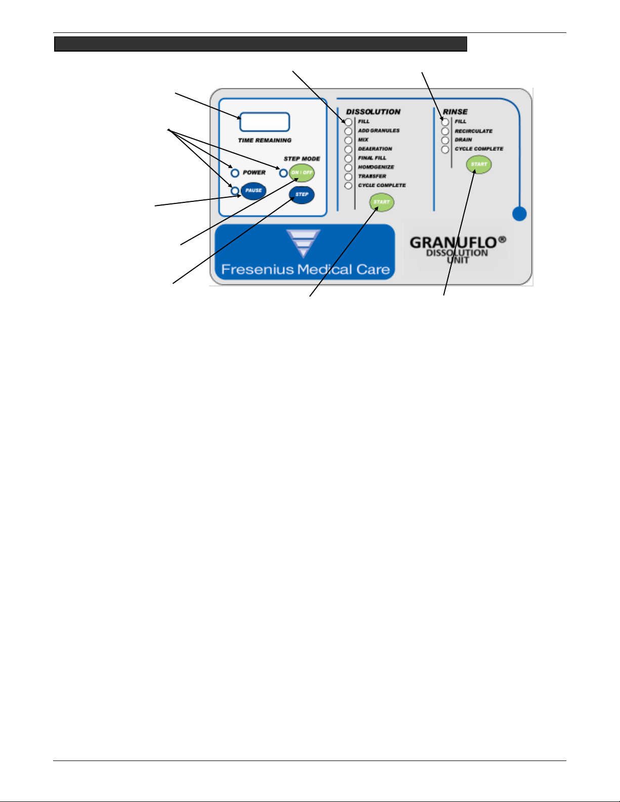
DIAGRAM 1: FRONT PANEL BUTTONS AND INDICATOR LIGHTS/CYCLE PROGRAM OVERVIEW
Dissolution Cycle consists of the following Operations:
FILL – Input water Fill Valve Opens and allows water into tank. Once water reaches Mid-Level Sensor the unit switches
to ADD GRANULES Operation. During the FILL Operation a Short Rinse Program is done before the water reaches the
Mid-Level Sensor.
ADD GRANULES – The indicator light is flashing and the unit is waiting for operator interaction. Once Dry Acid Powder
is added the operator is to press START Button. The unit proceeds to the MIX Operation.
MIX – The Mixer Motor turns on for 35 minutes, and then the unit automatically proceeds to DEAERATION Operation.
DEAERATION – The Unit sits motionless to allow excess bubble to rise out of solution for 2 minutes. The unit
automatically proceeds to the FINAL FILL Operation.
FINAL FILL – The Unit opens the Fill Valve and Closes the Fill Valve once the Final FILL Sensor is contacted by the rising
level in the tank. The program shall continue on to the HOMOGENIZE Operation.
HOMOGENIZE – The Mixer Motor runs to mix the contents of the tank for 10 minutes and then the program continues
to the TRANSFER Operation.
TRANSFER – The indicator light is flashing. Unit is waiting for Operator Interaction. Once Transfer Operation is
complete the program continues to the CYCLE COMPLETE Operation.
CYCLE COMPLETE – The Unit will sit motionless until next Operator Interaction is initiated.
Rinse Cycle consists of the following Operations:
1st FILL – Input water Fill Valve Opens and allows water into tank. Once water reaches 25-gallon sensor the unit
switches to RECIRCULATE Operation.
1st RECIRCULATE – The RECIRCULATE Operation runs for a 12-minute period. The spray ball and mixer motor runs for
duration of the time. Then, the program continues to DRAIN Operation.
1st DRAIN– In the DRAIN Operation the unit drains the contents of the tank. Then, the program continues to the 2nd
FILL Operation.
2nd FILL – Input water Fill Valve Opens and allows water into tank. Once water reaches 25-gallon sensor the unit
switches to RECIRCULATE Operation.
2nd RECIRCULATE – The RECIRCULATION Operation continues to run. The spray ball and mixer motor runs for duration
of the time. Then, the program continues to DRAIN Operation.
2nd DRAIN – In the DRAIN Operation the unit drains the contents of the tank. Then, the program continues to CYCLE
COMPLETE Operation.
CYCLE COMPLETE – The Unit shall sit motionless until Operator Interaction is initiated.
*PAUSE State and STEP Mode: For information on the use of PAUSE State and STEP Mode refer to Section 9: “Manual
Control Operations”.
Rinse Cycle START
Push Button
Dissolution Cycle START
Push Button
*STEP Push Button
*STEP Mode ON/OFF
Push Button
*PAUSE Push
Button
Dissolution Operation status
Indicator Lights
RINSE Operation status
Indicator Lights
Time Remaining
Indicator
Indicator Lights

8 P/N 450368 Rev I
DIAGRAM 2: EXTERNAL AND INTERNAL GRANUFLO DISSOLUTION UNIT II PARTS
Mixing Jets
Tank Filter Stand
25 – Gallon Sensor
Mid-Level Sensor
Final Fill Sensor
Spray Ball
Pump Dry Sensor (inside
base; below tank)
Transfer Hose
Motor Access Panel
Filter Housing
¾” Transfer Barb
Control Panel
Small Access Port Lid
Large Access Lid
Dissolution Tank
120 VAC Power Cord
Main Power Switch/Breaker
Water Inlet or Drain
Outlet…Location will
vary
Transfer Hose Holder
Main Transfer Ball Valve
Side Access Panel
Leveling Feet (All items under Unit)
External Parts
Internal Parts

P/N 450368 Rev I 9
SECTION 5: GRANUFLO DISSOLUTION UNIT II PREPARATION
1. Power Cord is connected to 115 Volt, 60 Cycle, Single Phase, 15 Amp, GFI protected circuit.
2. Be certain the Drain Hose is over a floor drain
3. Transfer Hose is connected to the Transfer Hose Holder of the GranuFlo Dissolution Unit II.
4. Make sure input water source is turned ON.
5. Power Switch is in the ON position.
NOTE: INPUT WATER PRESSURE DIRECTLY AFFECTS HOW FAST THE GRANUFLO DISSOLUTION UNIT II WILL FILL. THE MAXIMUM
INPUT WATER PRESSURE IS 60 PSI.

10 P/N 450368 Rev I
SECTION 6: RINSE CYCLE
1. Before initiating the RINSE CYCLE, the operator must ensure that the GranuFlo Dissolution Unit II
Access Port Lid is in place (do not fully secure) and the Main Transfer Ball Valve is in the CLOSED
position. Make sure input water supply valve is OPEN ( Figure 1).
Figure 1
2. The RINSE CYCLE consists of two RINSE Operations. Press the Rinse START button. The Fill Indicator
Light will illuminate indicating the RINSE CYCLE has started and the GranuFlo Dissolution Unit II is in
FILL Operation (Figure 2). Lift the Access Lid and look into the tank to verify that the tank is filling.
.
Figure 2 Figure 3
3. Once the 25 Gallon Level Sensor is reached, the process automatically
steps to RECIRCULATE Operation (Figure 3). The operation will run for a
twelve (12) minute period. During this operation, the Spray Ball and jets
shall operate in 3 minute intervals. With your safety glasses on, lift the
lid after the Spray Ball has stopped operating and ensure that the water
is level with 25 Gallon Level Sensor. Since the water will be swirling in the tank it is okay for the
level to be a little above the 25 Gallon Sensor, but you should ensure that the level is not rising.
During this time period, follow the procedure outlined on the following page to inspect and clean
the Spray Ball Ring if needed see Figure 4: Spray Ball Ring Inspection / Cleaning Instructions.
CAUTION! BEFORE INITIATING THE RINSE CYCLE, THE DRAIN HOSE MUST BE PLACED ABOVE A SUITABLE DRAIN. ALWAYS LEAVE
ACCESS PORT LID IN PLACE UNLESS MANUAL INSTRUCTS OTHERWISE.
CAUTION! IMMEDIATELY AFTER A COMPLETED RINSE CYCLE, MAKE A BATCH OF DRY ACID PRODUCT. DO NOT LEAVE THE
GRANUFLO DISSOLUTION UNIT II WITH ONLY TREATED WATER OR WETTED WITH ONLY TREATED WATER FOR 4 OR MORE HOURS SINCE
THE GRANUFLO DISSOLUTION UNIT II IS SUSCEPTIBLE TO BACTERIAL GROWTH. IF A GRANUFLO DISSOLUTION UNIT II IS FOUND TO BE
STANDING FOR 4 OR MORE HOURS WITH TREATED WATER OR WETTED WITH TREATED WATER, THEN A DISINFECTION CYCLE (SEE
SECTION 8.3 SODIUM HYPOCHLORITE (BLEACH) DISINFECTION, PAGE 23), MUST BE COMPLETED BEFORE THE DISSOLUTION CYCLE IS
STARTED.
Jets
The Granuflo II
Dissolution
Unit will fill
to the 25
GALLON
LEVEL
SENSOR.
25-Gallon
Sensor
Spray Ball
CLOSE Main Transfer Ball Valve by
turning the handle Counter
Clockwise until it stops.

R I N S E C Y C L E Continued
P/N 450368 Rev I 11
Inspect Spray Ball for correct operation:
Below Instructions is for Technical Service Use Only:
Figure 4: Spray Ball Ring Inspection/Cleaning Instructions
A. Remove the Small Access Port and look inside to check for
the Spray Ball Ring proper rotation.
B. Check the Spray Ball Ring for rotation.
SPRAY
BALL
RING
If Spray Ball Ring is clogged the water flow looks like
this, then call TECHNICAL SUPPORT (1-800-227-2572)
If Correct Spray and rotation of the Spray Ball Ring, then
proceed to step 4, pg 12.
D. Remove the nut below the Spray Ball to access the
Sprayer.
C. If the Spray Ball is stationary, push the PAUSE button.
RECIRCULATE Light will flash. Turn Main Power Switch OFF.
F. Turn main Power Switch ON. Press RINSE CYCLE START
button. PAUSE LED will turn off and RECIRCULATE LED will
not flash. Check for proper Spray Ring rotation before
continuing to pg. 12.
E. Clear the spray holes in both the Spray Ball Ring and Sprayer
of debris and reassemble.

R I N S E C Y C L E Continued
12 P/N 450368 Rev I
4. When the RECIRCULATE Operation is complete, the GranuFlo
Dissolution Unit II will switch to DRAIN Operation and empty rinse
water from the GranuFlo Dissolution Unit II to the floor drain.
5. At the completion of the DRAIN Operation, the GranuFlo Dissolution
Unit II will refill to the 25 Gallon Sensor. The Fill Indicator Light will
turn ON and the second RINSE Operation will start.
6. When the second RINSE CYCLE is finished, the GranuFlo Dissolution
Unit II will go to the CYCLE COMPLETE Operation. The Rinse Cycle
Complete Indicator Light will turn ON and the Drain Valve will remain
OPEN, allowing any residual rinse water to go down the drain.
 Loading...