


2008T BlueStar

PatientCard Reader
Installation Instructions
PatientCard Reader Installation Instructions
for
2008T BlueStar
Part Number 490330 Rev B
This document contains proprietary information of Fresenius USA, Inc. d/b/a Fresenius Medical Care North America
and its affiliates (“Fresenius Medical Care”). The contents of this document may not be disclosed to third parties,
copied, or duplicated in any form, in whole or in part, without the prior written permission of Fresenius Medical Care.
Fresenius Medical Care, the triangle logo, 2008, BlueStar, bibag and DIASAFE are trademarks of Fresenius Medical
Care Holdings, Inc., or its affiliated companies. All other trademarks are the property of their respective owners.
If there are any questions regarding these instructions, contact Fresenius Medical Care Technical Support at 800-227-2572.
© 2019, Fresenius Medical Care North America. All rights reserved.
™
Hemodialysis Machines
2008T PATIENTCARD READER INSTALLATION INSTRUCTIONS
Functional Board
Actuator-Test Board
Purpose:
The purpose of these instructions is to define the process of installing the PatientCard Reader onto a
2008T BlueStar hemodialysis machine.
Machine Prerequisite:
• 2008T BlueStar Functional software version 2.71 or greater*
• 2008T BlueStar Actuator-Test software version 2.32 or greater*
*Note: If a software update is needed, a 2008T BlueStar Standard Upgrade Kit (P/N 191137) must be ordered separately.
Required Tools:
• #2 Phillips screw driver
• 5 mm Allen Wrench
Procedure:
Caution: Assembly, installation, adjustment, or repair is to be performed by Fresenius Medical Care or by
persons trained by Fresenius Medical Care.
Software Verification
1. Power the machine on and enter Service Mode.
2. Select the Options screen button and enter debug by pressing and holding the CTRL key and then press
the and keys at the same time on the keyboard. Use the and keys to go to debug screen 3
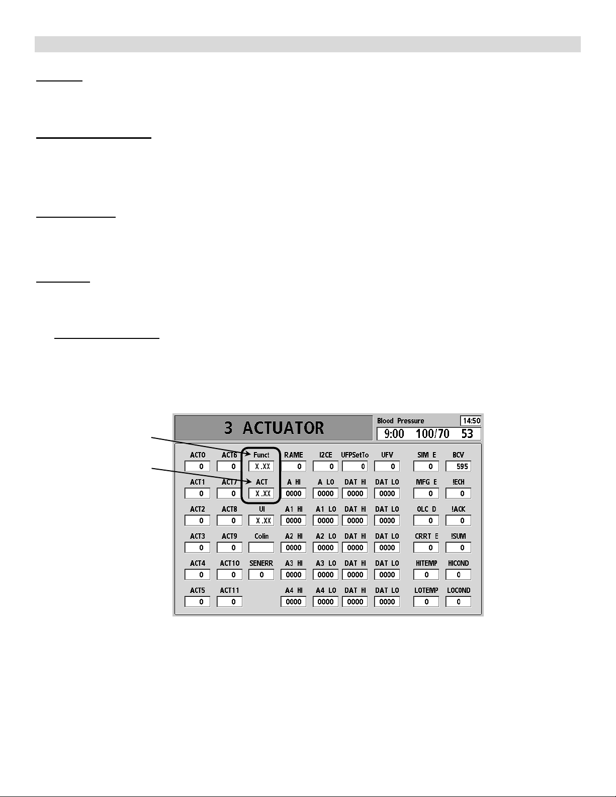
ACTUATOR
S/W Version
S/W Version
.
Figure 1
3. Using Figure 1 verify the Functional software version is 2.71 or greater and the Actuator-Test software
version is 2.32 or greater. Press the Escape key to exit debug.
4. If valid software versions are already installed, skip to the IV Pole Removal section on the next page.
5. Perform the 2008T BlueStar Software Update Instructions (P/N 490329) included in the 2008T
BlueStar Standard Upgrade Kit (P/N 191137).
P/N 490330 Rev B Page 1 of 10
2008T PATIENTCARD READER INSTALLATION INSTRUCTIONS
IV Pole Removal
The PatientCard Reader is incorporated into the IV Pole holder so the upper IV pole holder will need to be
replaced.
Note: The IV pole will need to be removed so remove the dialyzer holder and any other object that will
hinder the IV pole removal.
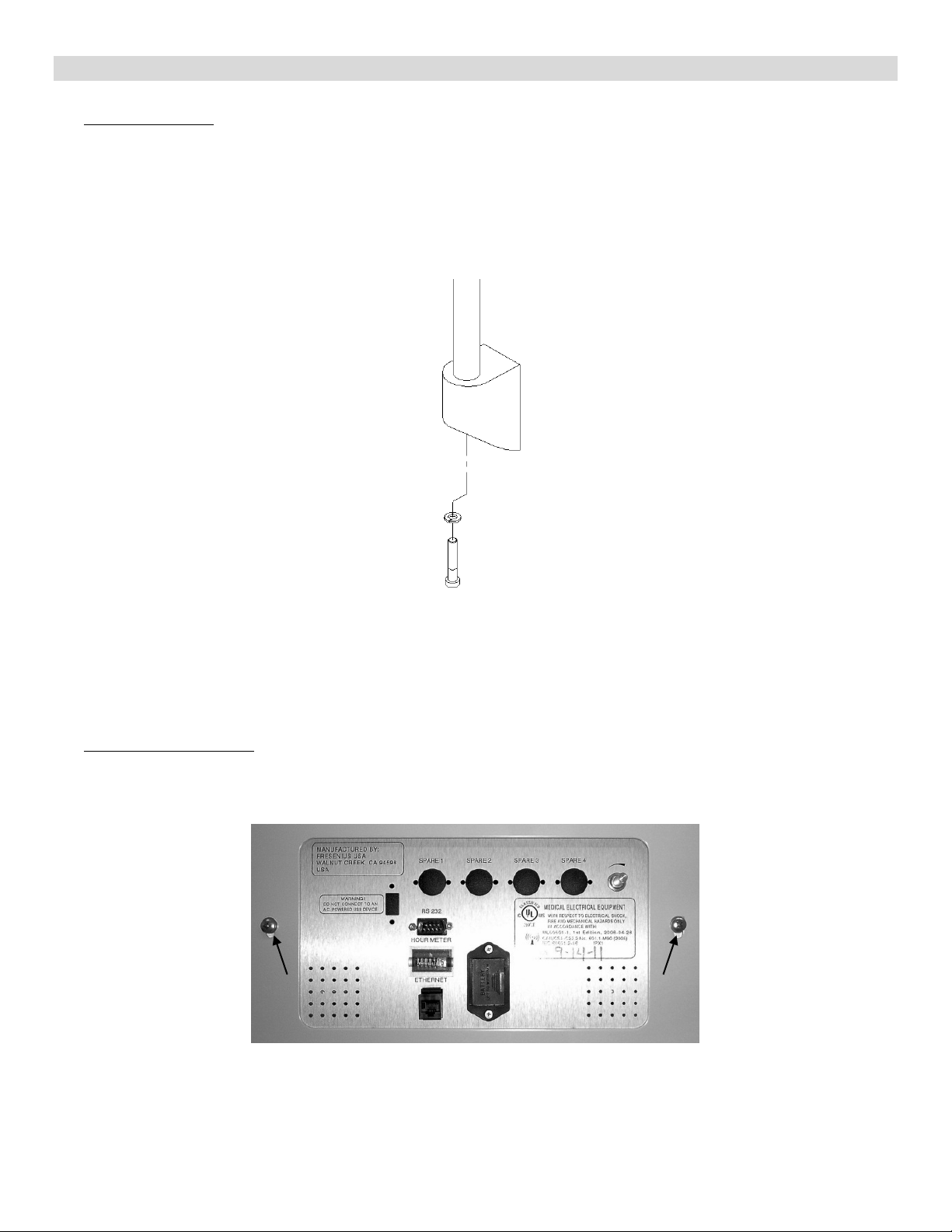
6. Power off the machine and locate the screw under the lower IV pole holder (see Figure 2).
Figure 2
7. Using a 5 mm Allen wrench, remove the screw securing the IV pole to the holder.
8. Slide the IV pole up and out of the lower and upper IV holder assemblies.
9. Set the IV pole aside.
Card Cage Preparation
10. Remove the two (2) screws securing the card cage into the cabinet (see Figure 3). Slide the card cage
out the front of the cabinet a few inches.
Figure 3
P/N 490330 Rev B Page 2 of 10
2008T PATIENTCARD READER INSTALLATION INSTRUCTIONS
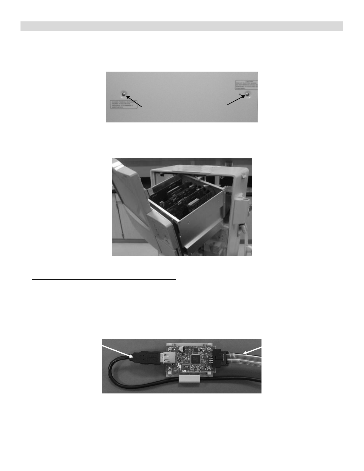
Serial Cable
USB Cable
Note: The middle panels has a ground wire attached. Take care not to damage this wire when removing
the panel.
11. Remove the middle panel covers. See Figure 4 for screw locations. Unplug the cover’s ground wire.
Figure 4 – Middle Rear Panel Screw Locations
12. Slide the card cage out as shown in Figure 5. This allows for access to the IV pole holder mounting
screws as well as the inside of the card cage.
Figure 5
Card Reader Adapter Board Assembly Installation
Caution: Care must be taken when handling circuit boards to prevent damage by Electrostatic Discharge
(ESD). Use appropriate ESD precautions when handling electronic components.
13. Locate the Card Reader Adapter Board included in the kit.
14. Connect the USB Cable (P/N 365067-08) into the card reader adapter board assembly as shown in
Figure 6.
(P/N 365067-08)
(P/N 191116)
Figure 6 – Card Reader Adapter Board
15. Connect the Serial Cable (P/N 191116) into the card reader adapter board assembly as shown in
Figure 6.
P/N 490330 Rev B Page 3 of 10
 Loading...