

Page 1
TS-TPI Turbine Pump Interface
Installation and Wiring Guide
Part Number: 000-0042 Rev. A
Copyright
©
December 2003
Page 2
NOTICE
INCON/EBW has strived to produce the finest possible manual for you, and to
ensure that the information contained in it is complete and accurate. However,
INCON/EBW makes no expressed or implied warranty with regard to its contents.
INCON/EBW assumes no liability for errors or omissions, or for any damages,
direct or consequential, that result from the use of this document or the equipment
which it describes.
This document contains proprietary information and is protected by copyright. All
rights are reserved. No part of this document may be reproduced in any form
without the prior written consent of INCON/EBW.
INCON/EBW reserves the right to change this document at any time without notice.
NOTE
Use the Table of Contents to find topics within this manual. Separate installation
instructions are provided for: the Needle Valve (PN 000-0045), the Calibration Kit
(PN 000-0043), and the LSU Transducer (PN 000-0058).
Need Help ? Mail Address (no packages):
INTELLIGENT CONTROLS INC
PO BOX 638
SACO ME 04072
Office Hours: 8 am to 5 pm EST, Monday through Friday
Sales – Orders 24 hour Technical Service
Delivery Schedules: RMA, Application Help:
Fax: (207) 283-0158 Fax: (207) 282-9002
Phone: (800) 872-3455 Phone: (800) 984-6266
email: sales@incon.com email: tech@incon.com
INCON/EBW is a wholly owned subsidiary of Franklin Electric and is member of the:
Franklin Fueling Systems Group. Visit our web site at:
T ank Sentinel®BriteSensors® and INCON®are registered trademarks of Intelligent Controls, Inc.
System Sentinel™ and System Sentinel ™ are trademarks of Intelligent Controls, Inc.
LS300 Auto-Learn® is a registered trademark of FE Petro®.
Copyright© 2003 – all rights reserved.
INSIDE FRONT COVER
TS-TPI Installation and Wiring
www.franklinfueling.com
Page 3

Table of Contents
1 Safety........................................................................................................... 1-1
2 TS-TPI Installation & Wiring.......................................................................... 2-1
3 Tank Sentinel / TS-TPI Interface................................................................... 3-1
4 TS-TPI Setup programming .......................................................................... 4-1
5 TS-TPI and Line Leak Testing....................................................................... 5-1
6 TS-TPI Data and reports............................................................................... 6-1
7 LINE Reports Setup...................................................................................... 7-1
8 Troubleshooting ............................................................................................ 8-1
TABLE OF CONTENTS Page TOC-1
TPI User’s Guide
TOC
Page 4
1 SAFETY
Graphic Symbol Conventions
Through out this User Guide these symbols will highlight information for your safety and the
proper functioning of this equipment. Read carefully the steps in this guide and pay special
attention to the steps where you see these symbols.
NOTE
Important information, tips, and hints are highlighted by the note graphic.
CAUTION messages are highlighted by the CAUTION graphic and contain instructions
that should be followed to avoid faulty equipment operation, or environmental hazards, or
personnel injury!
WARNING
that must be followed to avoid faulty equipment operation, or explosion or shock hazards. If
ignored, severe injury or death may result!
DANGER
must be followed to avoid an explosion or electrical shock hazard. If ignored, severe injury or
death will result!
ELECTRICAL DANGER
and contain instructions that must be followed to avoid an electrical shock. If ignored, severe
injury or death may result and even severe damage to electronic equipment.
messages are highlighted by the WARNING graphic and contain instructions
messages are highlighted by the DANGER graphic and contain instructions that
messages are highlighted by the ELECTRICAL DANGER graphic
SafetyFir st – Befor e Working on this Equipment
CAUTION
hydrocarbon liquids such as gasoline and diesel fuel. Installing or working on this equipment
means working in an environment in which these highly flammable liquids or vapors are
present. This presents a real risk of severe injury or death if these instructions and standard
industry practices are not followed.
Lock out and Tag circuit breakers before installation or service of this and associated equipment
Restrict access to the work area to only certified and trained installers or service personnel
Identify and mark the perimeter of the work area with signs, safety-cones and colored safety tape
Prevent unauthorized vehicle access (block access) into the work areas by using barriers,
barricades, and service trucks
Use only non-sparking tools when working in these Hazardous Areas
Check for presence of hydrocarbon vapors in containment sumps before entering and periodically
there after.
This equipment is designed to be installed in association with volatile
SAFETY Page 1-1
TS-TPI Installation and Wiring Guide
1
Page 5
ELECTRICAL DANGER
installing or servicing this equipment, pumps and related equipment. A potentially lethal
electrical shock hazard and the possibility of an explosion or fire from a spark can result if
the electrical circuit breakers are accidentally turned on during installation or servicing.
ALWAYS lock out and tag electrical circuit breakers while
ELECTRICAL DANGER
described in this manual, otherwise lethal electrical-shock-hazards could exist, which may cause
injury or death. Note: circuit breaker contact(s) can fail to open even when the circuit breaker lever
indicates off.
ELECTRICAL DANGER
automatically to run leak-tests at full line pressure. Automatic pump starts occur between
periods of product dispensing when there is no product being dispensed. BEFORE performing
any installation or service (such as replacing fuel-filters) – tag and lock-out all electrical power
sources to the submersible pump(s), pump controllers, and dispensers and relieve fuel-line pressure.
Failure to turn off power and relieve fuel-line pressure before work is started can result in: Electrical
shock, fuel spills, and fire or explosion hazard that may result in injury or death.
WARNING
may be present in the environment where this equipment is installed or serviced. Failure to follow
this instruction could result in a serious fire or explosion.
WARNING
the entire system. When no other regulations apply, follow NFPA 30, 30A, and 70 from the National
Fire Protection Association. Failure to do so could result in serious property damage, environmentalcontamination, and severe injury or death.
DO NOT smoke while working on or near this equipment. Highly flammable vapors
Follow all federal, state, and local laws governing the installation of this product and
Verify that no voltage exists before working-on, or wiring-to circuits
Electronic line leak detectors start submersible pumps
WARNING
pump manufacturer’s directions about how to do this). The pipeline from the submersible
pump to the dispenser, may be under pressure. If the line leak detector/plug (or any other
part of the submersible pump and fuel line) is removed without first relieving pressure, then a
product spill will occur. This can cause an environmental, fire, or explosion hazard, and may
result in injury or death.
WARNING
unauthorized personnel out of the hazardous work area. Use Safety Cones, Barricades,
Warning Signs, and Safety Tape, and block access with Barricades / service trucks to the
work area to avoid injury or property damage.
1
Page 1-2 SAFETY
Turn off all pump power and relieve pipeline pressure (reference and follow the
Avoid personnel injury or property damage: keep moving vehicles and
TS-TPI Installation and Wiring Guide
Page 6
WARNING
sparks when working on fuel dispensing equipment. Failure to follow these directions may
cause an explosion hazard, which could result in property damage and death.
Allow no source of combustion near the work area. Be careful not to cause
WARNING
If these vapors are inhaled they could cause dizziness or unconsciousness. If the vapors
were ignited they could explode causing serious injury or death.
CAUTION
Electric Code (NEC), and the Automotive and Marine Service Station Code (NFPA 30A in the
USA) before installation or maintenance. This installation is designed for submersible pumps
which have a Pump Control box in the station. If a pump control box does not exist, then the
system must be retrofitted to add a pump control box in the facility to comply with Codes.
CAUTION
vapors, if vapor levels are unsafe ventilate the sump with fresh air. While working in the sump
periodically check the atmosphere in the sump, if vapors reach unsafe levels exit the sump
and ventilate it.
CAUTION
or around a containment sump. Electronic and electrical petroleum monitoring equipment is
often housed in containment sumps designed to trap hazardous liquid spills and prevent
contamination of the environment.
These containment sumps can trap dangerous amounts of hydrocarbon vapors.
Refer to all applicable Federal, State, City and local codes, your National
Before entering a containment sump check for the presence of hydrocarbon
ALWAYS have a second person standing by for assistance when working in
CAUTION
ALWAYS cleanup and dispose of used absorbent/rags and petroleum resistant gloves in
approved waste containers. Cleanup refuse and dispose of these immediately to avoid
personnel injury from vapors or direct skin contact to also avoid possible fire or
environmental safety hazards.
Petroleum is carcinogenic – use adequate protection to avoid health hazards.
SAFETY Page 1-3
TS-TPI Installation and Wiring Guide
1
Page 7
2 TS-TPI INSTALLATION & WIRING
Overview
The TS-TPI Turbine Pump Interface is a communication device that allows the INCON TS-1001,
TS-2001 Automatic Tank Gauge (A TG) or other devices to communicate with the turbine pump
controllers (TPC). The TS-TPI is available as a stand alone unit, which requires it s own input
power, and as an integrated factory inst alled option in the TS-LS300 AutoLearn Line Leak Detector. The TS-TPI allows the ATG or other device to receive pump status information and, depending on the type of TPC, controls the pump.
In this chapter a brief description of each application is presented as well as the wiring of each
component for the particular application. Please contact Franklin Fueling System Technical
Support, (800)984-6266 if the TS-TPI is to be used in any other application.
Specific details of inst allation and the general programming instructions for the ATG is found in
the Tank Sentinel Installation Guide (part number 000-1050). Specific programming instructions
concerning the TS-TPI with the ATG will be covered in this Guide.
Look for your specific application on the following pages. Wire the components according to the
wire diagram and then go to the next chapter “Tank Sentinel/TS-TPI Interface” for information on
the features of the TS-TPI. The rest of the chapters provide instruction for programming the ATG
to take full advantage of the TS-TPI.
Here are the application options covered in this guide:
● TS-ATG with TS-TPI and TS-LS300 AutoLearn Console
● TS-ATG with TS-TPI, TS-LS300 AutoLearn Console and TPCs
● TS-ATG with TS-TPI and two TS-LS300 AutoLearn Consoles
● TS-ATG with TS-TPI, two TS-LS300 AutoLearn Consoles and TPCs
● TS-ATG with Stand alone TS-TPI and TPCs
● Stand alone TS-TPI with TPCs
ELECTRICAL DANGER
circuits described in this manual, otherwise lethal electrical-shock-hazards could exist, which
may cause injury or death. Note: circuit breaker contact(s) can fail to open even when the
circuit breaker lever indicates off.
ELECTRICAL DANGER
all electrical power sources to the submersible pump(s), pump controllers, and dispensers
and relieve fuel-line pressure. Electronic line leak detectors start submersible pumps automatically
to run leak-tests. Automatic pump starts occur between periods of product dispensing when there is
no product being dispensed.
Verify that no voltage exists before working-on, or wiring-to
BEFORE performing any installation or service lock-out and tag
Installation and Wiring Page 2-1
TS-TPI Installation and Wiring Guide
2
Page 8
TS-TPI specifications:
Input power: 120 - 240 Vac 50/60 hz (note: stand alone TS-TPI only. the integrated TS-TPI/TSLS300 does not require any additional power connection to the TS-TPI)
For indoor installation only, operating temperature 40 - 105° F (4 - 41° C)
Use Belden Cable #9365 - 18 AWG or equivalent
TS-TPI revision 2.3 or higher for use with MagVFC, STP-SCI, STP-SCIII, STP-SC, and IST-VFC
controllers. Limited functions available with STP-SCIII, STP-SC and IST-VFC controllers. See
Troubleshooting section for details.
Integrated TS-TPI/TS-LS300 uses PORT 1 exclusively for TS-LS300 communication and is not
available for TPC connections. The stand alone TS-TPI can use PORT1 for TPC connections.
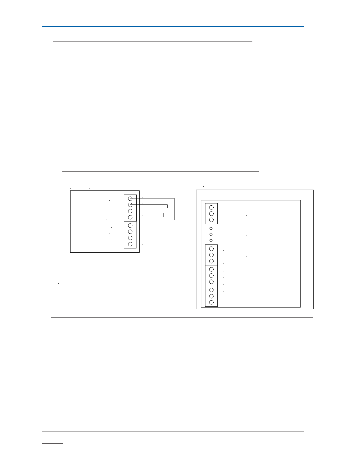
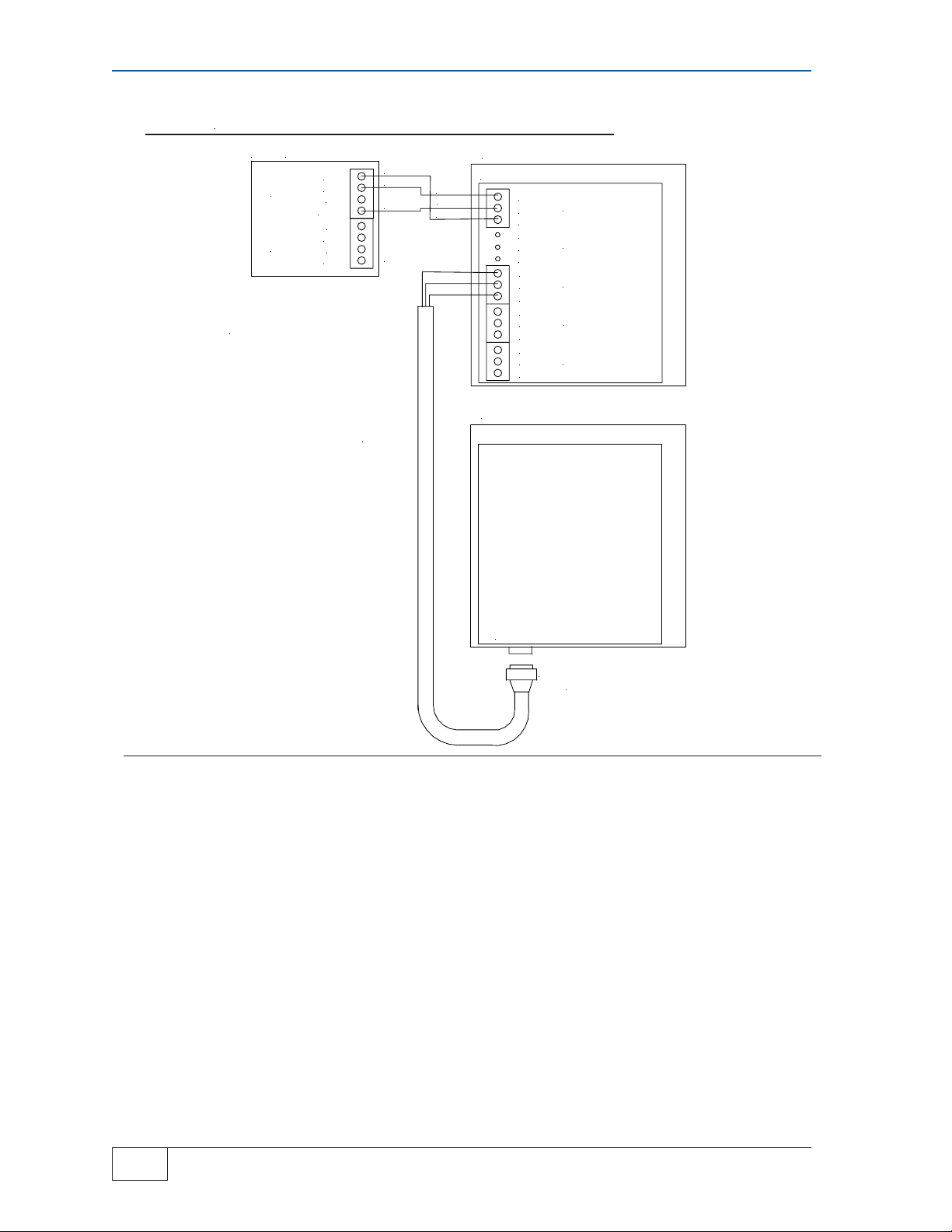
Integrated TS-TPI / TS-LS300 with Automatic Tank Gauge
TS-1001, TS2001
ATG
SEE TA N K SE N T INE L INS T AL LA T ION GUIDE
(PART # 000-1050) AND LS300 USER 'S GUIDE
(PART # 000-0040) FOR COMP LETE ATG AN D
LS300 WIRING INFORM AT ION
TS1001 OR TS2001 ON LY
485A
TS-LLD
INP UTS
485B
DSY
S,RTN
IN 1
GND
IN 2
GND
RED
BLACK
WHITE
CABLE-BELDEN
CONDUCTOR
#9365-18AWG
OR EQUIVALENT
BLACK
WHITE
RED
LS300
TPI BOARD
TXD 485GND
RXD 485+
TXD 485GND
RXD 485+
TXD 485GND
RXD 485+
TXD 485GND
RXD 485+
TXD 485GND
RXD 485+
HOST PORT
PORT 1
PORT 2
PORT 3
PORT 4
Figure 2-1
● This application provides communication between ATG and TS-LS300 only. The
Line Leak detector option is required on the ATG for operation.
● See Tank Sentinel Installation Guide and TS-L300 AutoLearn Installation Guide for
specific instructions for each component
2
Page 2-2 Installation and Wiring
TS-TPI Installation and Wiring Guide
Page 9
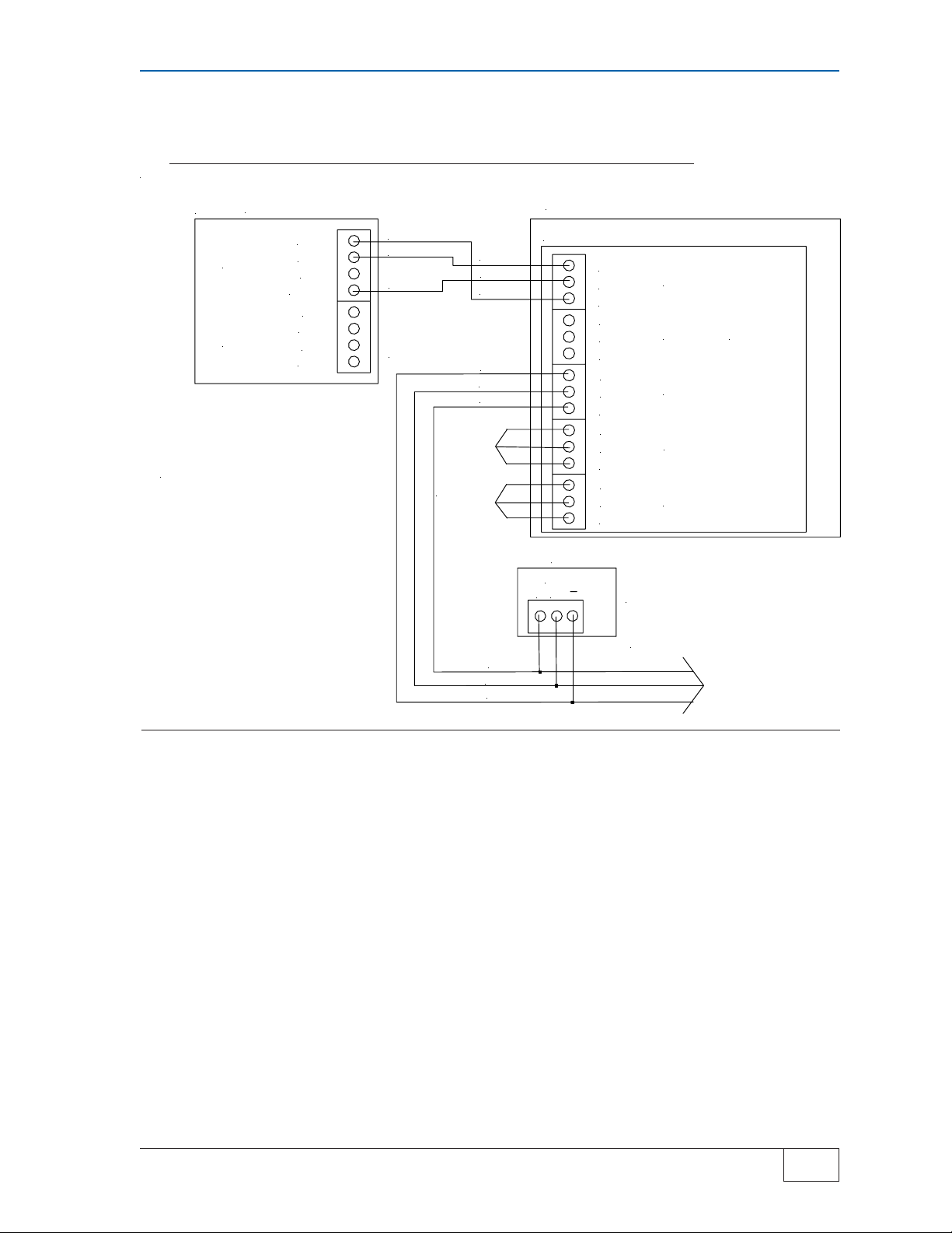
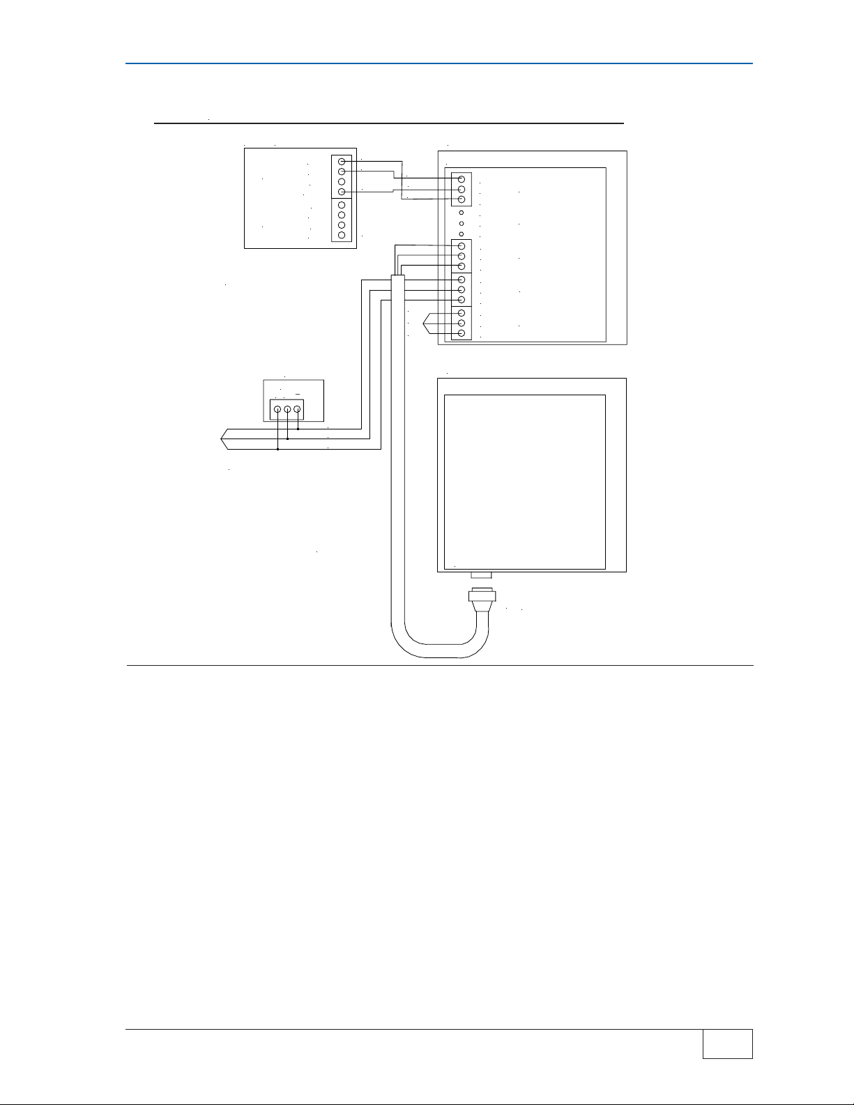
Integrated TS-TPI / TS-LS300 to Automatic Tank Gauge
TS-1001, TS2001 and TPCs
ATG
SEE TANK SENTINEL INSTALLATION GUIDE
(PART # 000-150), LS300 USER'S GUIDE
(PART # 000-0040), AND APPROPRIATE
TPC INSTALLATION AND OWNER'S MANUAL
FOR COMPLETE WIRING INFORMATION
TS1001 OR TS2001 O NL Y
485A
TS-LLD
INPU T S
485B
DSY
S,RTN
IN 1
GND
IN 2
GND
RED
BLACK
WHITE
CABLE-BELDEN
CONDUCTOR
#9365-18AWG
OR EQUIVALENT
ADDITIONAL
TPC
GROUPS
BLACK
WHITE
RED
BLACK
WHITE
RED
RED
WHITE
BLACK
LS300
TPI BOARD
TXD 485GND
RXD 485+
TXD 485GND
RXD 485+
TXD 485GND
RXD 485+
TXD 485GND
RXD 485+
TXD 485GND
RXD 485+
TPC
RS485
+ G
HOST PORT
PORT 1
NOT USED
PORT 2
PORT 3
PORT 4
CONTROLLERS MAY INCLUDE THE
MagVFC, STP-SCI, STP-SCIII,
IST-VFC, AND STP-SC
ADDITIONAL TPC CONNECTIONS
Figure 2-2
● This application provides communication between ATG, TS-LS300, and TPCs. The
Line Leak detector option is required on the ATG for full communication with TSLS300.
● See Tank Sentinel Installation Guide and TS-L300 AutoLearn Installation Guide for
specific instructions for each component
● Connect TPCs so all Stand alone TPCs are on the same port and Master/Slave
configured units are on their own port. Address TPCs so controllers on same port
have unique addresses. If similar type stand alone TPCs are installed on the same
port as Master/Slave TPCs the stand alone TPCs will be seen as Slave units.
Installation and Wiring Page 2-3
TS-TPI Installation and Wiring Guide
2
Page 10
TS-TPI / two TS-LS300 with Automatic Tank Gauge
TS-1001, TS2001
TS1001 OR TS2001 ONLY
ATG
485A
TS-LLD
INPUTS
SEE TANK SENTINEL INSTALLATION GUIDE
(PART # 000-1050) AND LS3 00 US ER 'S GU ID E
(PART # 000-0040) FOR CO M P LET E AT G A ND
LS300 WIRING INFORMATION
485B
DSY
S,RTN
IN 1
GND
IN 2
GND
PURCHASE
RS232 CABLE
LOCALLY
RED
BLACK
WHITE
CABLE-BELDEN
3 CONDUCTOR
#9365-18AWG
OR EQUIVALENT
BLACK
WHITE
RED
LS300
TPI BOARD
TXD 485GND
RXD 485+
TXD 485GND
RXD 485+
TXD 485GND
RXD 485+
TXD 485GND
RXD 485+
TXD 485GND
RXD 485+
LS300
HOST PORT
PORT 1
PORT 2
PORT 3
PORT 4
EXTERNAL
RS232 PORT
NO TS-TPI BOARD IN THIS LS300
IF TS-TPI IS PRESENT, REMOVE IT BEFORE
MAKING THE RS232 CONNECTION
Figure 2-3
● Provides communication between ATG and both TS-LS300 consoles. ATG
requires the Line Leak detection option for full operation of TS-LS300 and ATG
communication.
● Only one TS-LS300 has TS-TPI installed, if both have a TPI board remove the TPI
from one of the TS-LS300
● The RS232 cable is supplied by the customer
● TS-TPI configuration switch SW1 pole 3 is ON. See Figure 2-7 for more details and
switch settings on TS-TPI
2
Page 2-4 Installation and Wiring
TS-TPI Installation and Wiring Guide
Page 11
Wire diagram for TS-TPI with two TS-300 AutoLearn to
Automatic Tank Gauge TS-1001, TS2001 and TPCs
TS1001 OR TS2001 ONLY
ATG
485A
TS-LLD
INPUTS
SEE TANK SENTINEL INSTALLATION GUIDE
(PART # 000-1050) AND LS300 USER'S GUIDE
(PART # 000-0040) FOR COMPLETE ATG AND
LS300 WIRING INFORMATION
485B
DSY
S,RTN
IN 1
GND
IN 2
GND
RED
BLACK
WHITE
CABLE-BELDEN
3 CONDUCTOR
#9365-18AWG
OR EQUIVALENT
BLACK
WHITE
RED
ADDITIONAL
TPC
GROUPS
LS300
TPI BOARD
TXD 485GND
RXD 485+
TXD 485GND
RXD 485+
TXD 485GND
RXD 485+
TXD 485GND
RXD 485+
TXD 485GND
RXD 485+
HOST PORT
PORT 1
PORT 2
PORT 3
PORT 4
TPC
RS485
+ G
BLACK
WHITE
CONTROLLERS MAY INCLUDE THE
MagVFC, STP-SCI, STP-SCIII, VFC AND STP-SC
RED
LS300
PURCHASE
RS232 CA BL E
LOCALLY
EXTERNAL
RS232 PORT
NO TS-TPI BOARD IN THIS
TS-LS300 CONSOLE. IF TS-TPI
IS PRESENT REMOVE IT BEFORE
MAKING RS232 CONNECTIONS
Figure 2-4
● Provides communication between ATG, TPCs, and both TS-LS300 consoles. ATG
requires the Line Leak detection option for full operation of TS-LS300 and ATG
communication.
● Only one TS-LS300 has TS-TPI installed, if both have a TPI board remove the TPI
from one of the TS-LS300
● The RS232 cable is supplied by the customer
● Connect TPCs so all Stand alone TPCs are on the same port and Master/Slave
configured units are on their own port. Address TPCs so controllers on same port
have unique addresses. If similar type stand alone TPCs are installed on the same
port as Master/Slave TPCs the stand alone TPCs will be seen as Slave units.
● TS-TPI configuration switch SW1 pole 3 is ON. See Figure 2-7 for more details and
switch settings on TS-TPI
Installation and Wiring Page 2-5
TS-TPI Installation and Wiring Guide
2
Page 12
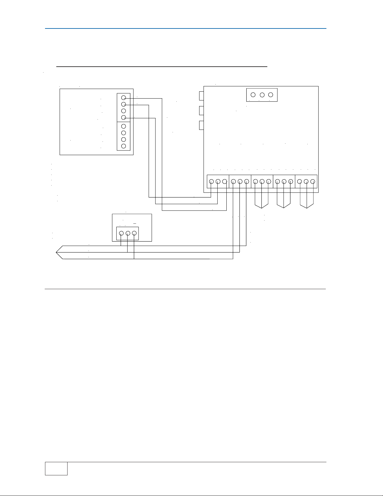
Stand AloneTS-TPI with Automatic Tank Gauge TS-1001 or
TS2001 and TPCs
ATG
SEE TANK SENTINEL INSTALLATION GUIDE
(PART # 000-1050), THIS TPI USER 'S GUIDE
AND APPROPRIATE
TPC INSTALLATION AND OWNER'S MANUAL
FOR COMPLETE WIRING INFORMATION
CABLE-BELDEN CONDUCTOR
#9365-18AWG OR EQUIVALENT
TS1001 OR TS2001 ONLY
485A
TS-LLD
INPU T S
485B
DSY
S,RTN
IN 1
GND
IN 2
GND
RED
BLACK
WHITE
TPC
RS485
+ G
ADDITIONAL
TPC CONNECTIONS
RED
WHITE
BLACK
TS-TPI
RESET
TPC FAULT
RESET
ALARM
SILENCE
BLACK
WHITE
STAND ALONE TPI
GND L2/N L1
INP U T POW ER
120 -240 Vac 50/60 hz
TXD 485-
RED
HOST PORT
GND
PORT 1
TXD 485-
GND
RXD 485+
WHITE
BLACK
PORT 2
TXD 485-
GND
RXD 485+
RED
CONTROLLERS MAY INCLUDE THE
MagV F C , ST P -SCI, STP-SC III, VFC
AND STP-SC
RXD 485+
ADDITIONAL TPC
GROUPS
PORT 3
TXD 485-
GND
PORT 4
TXD 485-
GND
RXD 485+
RXD 485+
Figure 2-5
● Communication between ATG and TPCs, no additional ATG options required for full
operation
● Stand Alone TS-TPI requires separate 120 - 240 vac, 50/60 hz, power
● See Tank Sentinel Installation Guide for specific ATG instructions
● TPCs that can be installed are MagVFC, IST-VFC, STP-SCI, STP-SC and STP-
SCIII. Available functions are limited on the IST-VFC, STP-SC and the STP-SCIII
controllers, see troubleshooting section for details
● Connect TPCs so all Stand alone TPCs are on the same port and Master/Slave
configured units are on their own port. Address TPCs so controllers on same port
have unique addresses. If similar type stand alone TPCs are installed on the same
port as Master/Slave TPCs the stand alone TPCs will be seen as Slave units.
2
Page 2-6 Installation and Wiring
TS-TPI Installation and Wiring Guide
Page 13
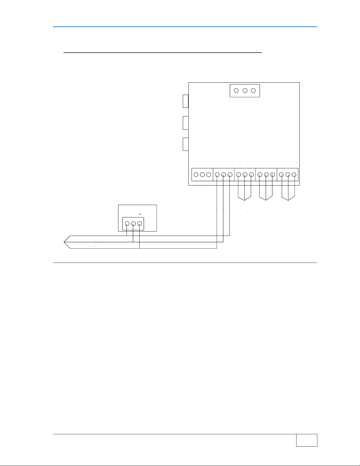
Stand AloneTS-TPI with TPCs
SPECIFICATIONS
Input power:
120 - 240 Vac 50/60 hz
TS-TPI
RESET
STAND ALONE TS-TPI
GND L2/N
INPUT POWER
L1
Indoor installation only.
Operating temperature:
40 - 105° F (4 - 41° C)
CABLE-BELDEN CONDUCTOR
#9365-18AW G O R E Q UIVA LE NT
ADDITIONAL
TPC CONNECTIONS
RED
WHITE
BLACK
● Communication between TS-TPI and TPCs. Use this application for remote
controller fault indication and controller fault reset.
TPC
RS485
+ G
TPC FAULT
RESET
ALARM
SILENCE
Figure 2-6
TXD 485-
RXD 485+
TXD 485-
PORT 3
GND
RXD 485+
TXD 485-
PORT 4
GND
RXD 485+
HOST PORT
GND
RXD 485+
BLACK
PORT 1
TXD 485-
GND
WHITE
RED
PORT 2
TXD 485-
GND
RXD 485+
ADDITIONAL TPC
GROUPS
CONTROLLERS MAY INCLUDE THE
MagVFC, STP-SCI, STP-SCIII, IST-VFC
AND STP-SC
● Stand Alone TS-TPI requires separate 120 - 240 vac, 50/60 hz, power
● TS-TPI reset switch will reset the TS-TPI in the event of a communication conflict.
● The TPC fault reset will reset a pump controller that is in a fault conditon. It will
only reset controllers that are indicating a fault alarm. If none of the controllers are
in alarm no reset will take place.
● Alarm Silence button will silence the audible alarm but not clear the fault.
● Connect TPCs so all Stand alone TPCs are on the same port and Master/Slave
configured units are on their own port. Address TPCs so controllers on same port
have unique addresses.
Installation and Wiring Page 2-7
TS-TPI Installation and Wiring Guide
2
Page 14
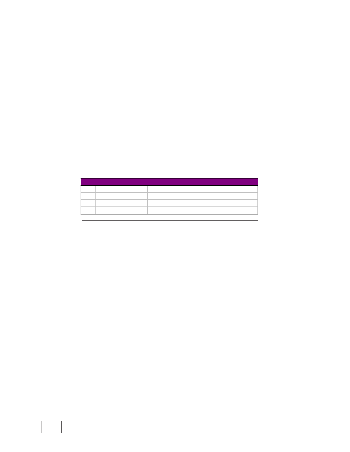
TPI Configuration Switch
Locate the single dip switch on the TS-TPI board labeled SW1.
This set of switches sets how the various ports communicate. The host (ATG) and Pump
Controllers all communicate using RS-485 connections. The TS-LS300 communicates using RS-
232.
The Factory default setting is switches 1, 2 and 3 are OFF and switch 4 is ON. When a second TS-
LS300 is used (more than 4 pipelines at a site) switch 3 is set to the ON positon, see Figure 2-7
SW1 Stand Alone TS- TPI TS-TPI in TS-LS300 Two TS- LS300 in use
1 OFF OFF OFF
2 OFF OFF OFF
3OFF OFF ON
4ON ON ON
Figure 2-7
2
Page 2-8 Installation and Wiring
TS-TPI Installation and Wiring Guide
Page 15

3 TANK SENTINEL/TS-TPI
INTERFACE
Overview
The Turbine Pump Interface (TS-TPI) hardware has been developed to facilitate communications of
the Turbine Pump Controllers (TPC) operating conditions with the INCON Tank Sentinel Automatic
Tank Gauge (ATG) consoles via the RS-485 port.
The integration of ATG , TS-TPI and TPC allows the ATG to intervene when pumps experience
certain fault conditions by resolving the fault and enabling the pump to continue dispensing fuel. In
addition to this, the ATG keeps an alarm history to aid in troubleshooting. A technician can review an
alarm history report at the site or remotely via System Sentinel® and System Sentinel Anyware® .
The TS-TPI requests status and fault conditions of the TPCs. This information is transmitted to the
ATG on demand. The ATG can then make this status available for purposes of:
● Displaying, Printing and Faxing Pump Controller Status
● Resetting Pump Controllers
● Making Pump Controller Status available to System Sentinel
Sentinel Anyware
®
®
and System
● Basic Operation Features
There are several basic operation features listed below and detailed further in separate chapters of
this manual.
Monitor, Record and Reset Pump Controller Faults
The primary feature is that the ATG maintains the state of the Pump controller such that it continues
to run and function without user intervention. The Pump Controller will stop a pump when a fault
condition exists. The A TG monitors pump controllers through the RS-485 port for fault conditions.
When fault conditions are received, the ATG will manage them by reporting alarms, silencing the
audible alarms on the controllers, and resetting the controller when appropriate.
Fault Diagnostic Capabilities
The secondary feature provides fault detection diagnostics. The ATG will take control of the pumps
when certain fault conditions are active in the ATG . For example, if a site has multiple t anks of the
same product and one of the tanks gets overfilled, the A TG will make the over filled tank the priority
tank, even if it is not programmed as the priority tank, until the over fill conditon is corrected. Pump
Controller alarms have been added to the alarm processing code of the tank gauge.
Level Management
The third feature allows a customer to utilize the ATG to control the “mode” the pumps use to draw
down product in two or more tanks with the same product. The “Leveling Mode” alternates the
pumps so that the tank levels are equal as the tanks are being drawn down. The “Priority Mode”
gives one pump priority over the others while it draws product down. A pump remains in “Priority
Mode” until an user specified reserve percentage level is reached. The tank gauge then gives
priority to another pump and it then draws down the product from another tank.
TANK SENTINEL/ TS-TPI INTERFACE Page 3-1
TS-TPI Installation and Wiring Guide
3
Page 16

In “Leveling Mode”, the ATG keeps the levels on multiple tanks the same and in the
“Priority Mode”, a specified tank will draw down to its reserve percentage before other
tanks are called upon.
The ATG also performs tank level management by generating alarms to warn the
operator of High and High High product limits, Low and Low Low product limits, water
levels limits and even an obstruction on the pump motor. The ATG can shut down
pumps, turn on pumps and change priority based on the active alarm at the ATG . For
example, if the water level in the tank is within two inches of the user defined pump
height the ATG will indicate the “Pump in Water” alarm and shut down the pump. The
A TG will prevent the pump from operating until the water level is reduced.
For Overfill Management the ATG will generate an alarm to warn the operator when
the product level in the tank exceeds the High or High High limits. If these conditions
occur, the ATG will change the tank priority in the group and make it the primary tank
so it will be the first tank to draw down product until the product level drops below the
High level limit.
TS-LS300 report, Leak Test Initiating Capabilities
The TS-TPI allows the TS-LS300 AutoLearn Line leak detection to communicate
product pipeline status. The A TG can respond to TS-LS300 alarms and print report s
of pipeline status. Reports can be scheduled by the end user . The user can schedule
precision line tests at any time in the ATG. Then the ATG , communicating throught
the TS-TPI, will initiate the line test. These tests are in addition to the tests the TSLS300 will do automatically .
TS-TPI Setup Programing Operations
The ATG Setup Programming menus allow for the TS-TPI feature to be enabled. An
Auto-configuration (AUTO CFG) is then performed, which sets up the TS-TPI system
for the first time, adding menus to the setup display . The ATG will detect the number
of pump controllers that are connected and will configure the ATG to monitor them.
The AUT O CFG updates the system configuration with the number of pump controllers connected, what type of controller, how the controllers are grouped and how the
associated pumps are to be managed.
The user Configuration menus control the pump name, tank association, pump
height, pump mode and reserve setting.
Data Display and Reports
On the ATG a pump controller Display menu is available from the console to allow
viewing of live and updated information about the pump controller. The ATG will also
monitor the pump controllers for information such as: status, faults, volts, amps,
watts, frequency, flow, pressure, temperature, dip switch settings, and sof tware
version.
The Pump Controller Status Report provides the same information found in the
Display menu. A separate TPI setup Report shows the various Group, Pump and
Tank associations.
3
Page 3-2 TANK SENTINEL/ TS-TPI INTERFACE
TS-TPI Installation and Wiring Guide
Page 17

Diagnostic Operations
A pump controller Diagnostic menu is available on the console display to allow a user
to reset a pump controller from the ATG . Another diagnostic function that is available
is the ability to enable automatic calibration of the pump controller and its pumps.
Remote Management
The remote management feature allows an interface within System Sentinel or
System Sentinel Anyware to acquire and display pump controller st atus. This feature
allows the user to remotely poll data from the ATG including pump controller status
and alarms. A pump Controller Interface screen in Site Link shows controller status.
TANK SENTINEL/ TS-TPI INTERFACE Page 3-3
TS-TPI Installation and Wiring Guide
3
Page 18

TPI ENABLE (UP/DOWN)
YES
TPI ENABLE (UP/DOWN)
NO
TPI
ENABLE
SETUP MENU (MORE)
TPI
4 TS-TPI SETUP PROGRAMMING
SELECT MENU OPTION
SETUP UPGRADE LANGUAGE DATALOG
TPI
ENABLE PUMP GROUP
TS-TPI Menu
H U
MENU
7
½ Press this key and follow the
highlighted sequence below...
M1 M2 M3 M4
M1 M2 M3 M4
NOTE
Prior to Enabling TPI, the System configuration for
Number of Tanks is required. Refer to the Tank
Sentinel Setup Programming Guide.
TPI ENABLE (user entry)
Description of Step s:
Here are the SELECT MENU OPTION menu
names displayed.
1) Press the M1 key to display the SETUP menu.
Here is the main SETUP MENU display
2) Press the DOWN key several times until the TPI
menu name is displayed.
“TPI” may be aligned with any of the menu keys
(M1--M4), depending on what other features are
programmed on enabled. for this example TPI is
aligned with M1
3) Press the M1 key to display the TPI menu
M1 M2 M3 M4
Here is the TPI ENABLE menu.
4) Press the M1 key to display the TPI ENABLE
user entry field. The default selction is NO. Choose
YES to enable TPI programming and subsequent
menus.
5) Use the UP/DOWN keys to change the selection
to YES.
6) Press the ENTER key to accept the entry .
The display returns to the TPI menu, which now
shows the Pump and GROUP menus.
TS-TPI SETUP PROGRAMMING Page 4-1
TS-TPI Installation and Wiring Guide
4
Page 19

TPI PUMP
AUTOCFG
TS-TPI PUMP Menu(s)
SETUP MENU (MORE)
COM PORTS CVS
TPI
TPI
ENABLE PUMP
GROUP
TPI PUMP
AUTOCFG PUMP1 PUMP2
• AUTO CFG (user entry)
• NO PUMPS “READ ONLY”
• PUMP N Menus (both)
AUTO CFG (user entry)
Description of Step s:
1) Press the MENU key to display the SELECT
MENU OPTION menu.
NOTE
H U
MENU
7
Before preforming AUTO CFG verify all
TPCs dip switches are set correctly. If
TPC switches are changed after AUTO
CFG the ATG will need to be Cold
Booted and the AUTO CFG procedure
repeated.
2) Press the M1 key under the word SETUP to
display the SETUP MENU menu.
3) Press the DOWN key until the TPI menu is
displayed (TPI appears as the last menu item).
TPI may be aligned with any of the menu keys
(M1 -- M4), depending on what other features are
programmed or enabled.
4) Press the M3 key to display the TPI menu.
Here is the main TPI menu, which shows ENABLE, PUMP and GROUP...
5) Press the M2 key to display the PUMP menu.
M1
K X
DOWN
SP ACE
M1 M2 M3 M4
M1 M2 M3 M4
Here is the TPI PUMP menu, which only shows
AUTO CFG
6) Press the M1 key to start the AUTO CFG
process.
Here is the TPI PUMP menu, which now shows
AUTO CFG, PUMP1, PUMP2, ...
Please read the following note about Auto-Configuration for your better understanding of this feature.
4
Page 4-2 TS-TPI SETUP PROGRAMMING
M1 M2 M3 M4
TS-TPI Installation and Wiring Guide
Page 20

AUTO-CONFIGURATION NOTE
SETUP MENU (MORE)
EXIT SYSTEM TANKS PROBES
SETUP INFO (MORE)
NO.LINES NO.SENS NO.PUMPS
NUMBER OF PUMPS READ ONLY
2
The AUT O CFG function is used to invoke the routines which query the TPI for the number of pump
controllers attached to the TS-TPI and other controller and pump related information.
When AUT O CFG is started, the tank gauge scans the TS-TPI for all the pump controllers attached
to the TS-TPI. For each controller found, a corresponding pump number will be displayed (e.g. if the
TS-TPI finds two controllers, there will be a Pump 1 and a Pump 2). Their types will be stored in the
TYPE Menu configuration and the number of controllers will be stored in the NO. PUMPS configuration.
The Auto-Configuration process will automatically update the following READ ONLY configuration
settings:
• NO. PUMPS (in System Menu)
• PUMP ADDRESS
• PUMP TYPE
• GROUP TYPE
• PUMP GROUP
See the Tank Sentinel Setup Programming Guide for more information on programming the ATG to
include Lines for TS-LS300 PROGRAMMING.
Number of Pumps Menu
NO.PUMPS “READ ONL Y”
Description of Step s:
The number of pumps information is displayed
under the SYSTEM menu. Return to the main
SETUP MENU display , which shows...
1) Press the M2 key to display the SYSTEM
menu.
2) Press the DOWN key until NO.PUMPS is
displayed...
READ ONL Y NOTE
Fields that display the words “READ ONL Y” in the
upper right corner have been automatically filled in
by the Auto-Configuration process. These fields are
not editable. The next Auto-Configuration process
will over-write these fields and values.
M1 M2 M3 M4
K X
DOWN
SP ACE
3)Press the M3 key to display the number of
pumps information...
The number represents the number of pump
controllers that the TPI device has detected.
The data on display “2” was generated from
Auto-Configuration.
4) Press the CANCEL key twice, to return to the
SETUP MENU menu.
M1 M2 M3 M4
NOTE
TS-TPI SETUP PROGRAMMING Page 4-3
TS-TPI Installation and Wiring Guide
NO.PUMPS may be aligned with
any of the menu keys (M1--M4),
depending on what other features
are programmed or enabled. For
this example, the menu is aligned
with the M3 key .
4
Page 21

PUMP N Menu(s)
PUMP N (MORE)
NAME TYPE GROUP ADDRESS
NAME PUMP N A ... M
PUMP1 BACKSPACE
• NAME (user entry)
• TYPE “READ ONLY”
• GROUP “READ ONLY”
• ADDRESS “READ ONLY”
• TANK (user entry)
• HEIGHT (user entry)
NAME (user entry)
Description of Step s:
The PUMP N menu displays six subsequent
fields, including TANK and HEIGHT (scroll
down)...
1) Press the M1 key to display the NAME
PUMP N user entry field...
The default name of “PUMP 1 is displayed...
2) Press the M4 key to backspace and
erase the “PUMP 1” default name.
3) Use the keypad to enter a unique name
for each pump, up to 8 characters long (See
NOTE below).
Remember:
Use the SHIFT key to change the keypad for
A...M to N...Z and to (numeric) 1-9, 0, ., =/-,
and SP ACE (a blank space)
NOTE
In the following examples, “N” represents any pump
number - 1, 2, 3 and so on.
M1 M2 M3 M4
M1 M2 M3 M4
4) Press the ENTER key to accept the data
entry .
The display returns to the PUMP N menu.
Repeat the user entry steps for each pump.
NOTE
4
Page 4-4 TS-TPI SETUP PROGRAMMING
The Pump name can be up to 8 alpha/numeric characters. This alias
is used throughout the system in the display and reports. An example
name would be UNLEADED. The name is not automatically updated
or over-written by an AUT O CFG operation.
TS-TPI Installation and Wiring Guide
Page 22

TYPE “READ ONL Y”
TYPE PUMP N READ ONLY
VFC
PUMP N (MORE)
NAME TYPE GROUP ADDRESS
PUMP N (MORE)
NAME TYPE GROUP ADDRESS
GROUP PUMP 1 READ ONLY
2
Description of Steps:
1) Press the M2 key to display the TYPE PUMP
N “READ ONL Y” field...
In this example, the type “VFC” is displayed...
There are five types of controller displays VFC,
SC, SCIII, SCI and VFCIV . The displayed TYPE
PUMP coresponds with the following FE Petro
controllers:
SC STP-SC
SCI STP-SCI
SCIII STP-SCIII
VFC IST-VFC
VFCIV MagVFC
M1 M2 M3 M4
2) Press the CANCEL key to return to the
PUMP N menu.
GROUP “Read Only”
Description of Steps:
1) Press the M3 key to diplay the GROUP
PUMP N “READ ONL Y” field...
In this example, the group “2” is displayed...
2) Press the CANCEL key to return to the
PUMP N menu.
CANCEL
M1 M2 M3 M4
This menu item defines which pump is connected to which TS-TPI port number. A group
number of 1, 2, 3, or 4 will indicate that the pump is on that port number. The TS-LS300
occupies Group 1 in the factory installed TS-TPI/TS-LS300, therefore the first pump group is
Group 2 and is connected on PORT 2. The Stand Alone TS-TPI has all ports and therefore all
groups available to TPCs.
TS-TPI SETUP PROGRAMMING Page 4-5
TS-TPI Installation and Wiring Guide
4
Page 23

ADDRESS PUMP 1 READ ONLY
0
ADDRESS “READ ONL Y”
PUMP N (MORE)
NAME TYPE GROUP ADDRESS
TANK ASSOCIATION PUMP 1 NUMERIC
0BACKSPACE
PUMP N (MORE)
TANK HEIGHT
Description of Step s:
1) Press the M4 key to display the ADDRESS
PUMP N “READ ONL Y” field...
In this example, address “0” is displayed...
The address range is from 0-31.
M1 M2 M3 M4
2) Press the CANCEL key to return to the PUMP
N menu.
Press the DOWN key to display the TANK and
HEIGHT user entry menus...
TANK (user entry)
Description of Step s:
1) Press the M1 key to display the TANK ASSOCIA TION PUMP N user entry field...
The default TANK ASSOCIATION number “0” is
displayed...
The user selects the tank number associated with
PUMP N. The values range from 0-8(0=none, or
the maximum number of tanks available for the
ATG model)
NOTE: This will allow a pump to be associated
with a tank. If the pump is not associated with a
tank (i.e. for level monitoring by the tank gauge),
then NONE may be chosen, but this will disable
some features of the pump controller interface for
that controller. If a t ank has multiple pumps in it,
more than one controller may be associated with
the tank.
CANCEL
K X
DOWN
SP ACE
M1 M2 M3 M4
2) Use the keypad to enter the tank number .
In the event that a number is already entered and
needs to change, press the M4 key to backspace
and erase the entry . The default “0” tank number
will be displayed.
4
Page 4-6 TS-TPI SETUP PROGRAMMING
TS-TPI Installation and Wiring Guide
Page 24

3) Press the ENTER key to accept data entry .
HEIGHT PUMP 1 NUMERIC
+7.000000 BACKSPACE
PUMP N (MORE)
TANK HEIGHT
PUMP N (MORE)
TANK HEIGHT
The display returns to the PUMP N menu. Repeat
the user entry steps for each pump.
HEIGHT (user entry)
1) Press the M2 key to display the HEIGHT PUMP
N user entry field...
ENTER
The default HEIGHT of “+7.0”(inches) is displayed...
2) Press the M4 key to backspace and erase the
“+7.000000” default height number.
NOTE: HEIGHT is the distance (in inches or
millimeters) between the bottom of the pump to
the bottom of the TANK. this allows the pump
height to be set by the user, which af fect s the
handling of the DRY TANK, BLOCKED INTAKE,
and PUMP IN WATER alarms. This variable
defaults to 7 inches and is user-programmable.
3) Use the keypad to enter the height value.
4) Press the ENTER key to accept data entry .
The display returns to the PUMP N menu showing
T ANK and HEIGHT.
To repeat these steps for the next pump:
M1 M2 M3 M4
Press the CANCEL key to display the TPI PUMP
menu, which displays AUT O CFG, PUMP 1,
PUMP2, ...
Repeat each PUMP N Menu step for every pump
number.
When these entries are completed...
Press the CANCEL key to display the main TPI
menu, which displays ENABLE, PUMP and
GROUP.
M1 M2 M3 M4
TS-TPI SETUP PROGRAMMING Page 4-7
TS-TPI Installation and Wiring Guide
4
Page 25

TPI Group Menu
TPI
ENABLE PUMP GROUP
TPI GROUP
GROUP1 GROUP2 GROUP3 GROUP4
GROUP 2
TYPE MODE
TYPE GROUP 2 READ ONLY
MASTER SLAV
• TYPE “READ ONLY”
• MODE (user entry)
• RESERVE (user entry)
TYPE “READ ONL Y”
Description of Step s:
Here is the main TPI menu, displaying
ENABLE, PUMP and GROUP...
1) Press the M3 key to display the TPI
GROUP menu...
Here is the TPI GROUP menu displaying
GROUP numbers 1 to 4 (zero LS-300s)
GROUP MENU NOTES
The Group menu is not available when pump controllers
are not connected/programmed with the TS-TPI device.
The Group menu name appears on the display but it does
not function.
Group 1 is removed from the display if one LS-300 is
connected to the TS-TPI. Groups 1 and 2 are removed
when two LS300s are connected. All Group s are displayed
if zero LS-300s are connected.
M1 M2 M3 M4
2) Press the (M) key of the group number to
be displayed. For this example, press M2 to
display the GROUP 2 menu...
Here is the GROUP 2 menu displaying TYPE
and MODE...
3) Press the M1 key to display the TYPE of
group as detected during Auto-Configuration.
This is a READ ONL Y field.
In this example, the type “MAST SLA V” is
displayed...
4) Press the CANCEL key to return to the
GROUP 2 menu.
To repeat the user entry steps for each
group, press CANCEL again to display the
TPI Group menu.
M1 M2 M3 M4
M1 M2 M3 M4
CANCEL
NOTE
4
NOTE: Please read the MODE Notes to gain a better understanding of the MODE
and RESERVE features.
Page 4-8 TS-TPI SETUP PROGRAMMING
TS-TPI Installation and Wiring Guide
Page 26

MODE “User Entry” Note
MODE GROUP 2 (UP/DN)
NONE
GROUP 2
TYPE MODE RESERVE
MODE GROUP 2 (UP/DN)
PRIORITY
(Mode functions are not available with STP-SC, STP-SCIII or IST-VFC)
MODE allows the operator to select which Level Management mode to use for a particular group. The
choices are NONE, LEVELING, and PRIORITY:
• Selecting NONE means NO level management mode for the Group (no Reserve to enter). This is
used for Groups with TPCs configured as stand alone controllers.
• Selecting the LEVELING mode seeks to maintain an equal level of fuel in each tank by placing
pump controllers associated with the tank containing the most amount of fuel to priority. This will
force the pump with the highest level of fuel to activate when the dispenser switch is activated (no
Reserve to enter).
• Selecting the PRIORITY option enables a mode that seeks to drain one tank before the other
tank(s). Only when the PRIORITY mode is selected the RESERVE menu will appear.
Reserve Configuration Note
RESERVE is set after choosing the PRIORITY MODE. This entry sets the reserve level of fuel remaining in the tank. The programming defines this percentage as an “empty” tank and is programmed in %
full.
For example, setting the Reserve to 20% means, when the tank is 20% full it is considered “empty”.
This will trigger two events; the ATG will change the priority of the pumps so a pump starts pumping
fuel from a different tank and lowers the priority of the pump in the tank that has reached its Reserve.
This helps to prevent the faults Dry Run and PUMP in W ater. If all tanks reach the Reserve level the
pumps will function in leveling mode.
Mode Type and Reserve Note
The STND ALON “type” designated the GROUP as a Stand Alone Group without any Master/Slave
associations. Members of the group consists of only one pump and one controller . The menus
MODE and RESERVE are not enabled for S tand Alone TYPE. This completes Setup Programming
for this type.
The MAST SLA V ‘type’ designates the GROUP as a Master/Slave configuration. The group consists
of more than one pump controller. This “type” is further defined by the kind of Level Management
“mode” either Leveling or Priority . If Priority is selected, the user is required to enter a value for
RESERVE.
MODE (user entry)
Description of Step s:
Here is the MODE GROUP 2 user entry
field display . NONE is the default setting...
K X
DOWN
SP ACE
1) Use the UP/DOWN keys to change the
default mode and scroll through the other
modes - LEVELING and PRIORITY...
2) Press the ENTER key to accept data
entry . This entry returns the display to the
GROUP N menu.
G T
UP
+/-
ENTER
If PRIORITY is selected,
Proceed to the RESERVE
menu, which is described
next...
TS-TPI SETUP PROGRAMMING Page 4-9
TS-TPI Installation and Wiring Guide
4
Page 27

RESERVE (user entry)
GROUP 2
TYPE MODE RESERVE
RESERVE PERCENT GROUP 2 NUMERIC
20 BACKSPACE
Description of Step s:
Here is the GROUP 2 main menu, displaying
TYPE, MODE and RESERVE...
1) Press the M3 key to display the RESERVE
menu...
Here is the RESERVE user entry field displaying the “percent full” value for GROUP 2 (in
Priority mode). The default setting is 20.
2) Press the M4 key to backspace and erase
the default percent value. this will clear the
field.
3) Use the keypad to enter a percent value for
each group.
4) Press the ENTER key to accept data entry .
This entry returns the display to the GROUP N
menu, displaying TYPE, MODE, and RESERVE.
5) Press the CANCEL key to return to the TPI
GROUP menu, displaying GROUP 1 to
GROUP 4.
Proceed to the next group number menu.
Repeat the steps above to set the reserve
percent for each group that is in Priority Mode.
M1 M2 M3 M4
M1 M2 M3 M4
ENTER
When set up programming is completed, follow the Exiting Setup Mode
steps (next section) to return the Tank Sentinel to the Run Mode.
Exiting Setup Mode
EXIT SETUP (user entry)
Description of Step s:
1)Press the CANCEL key to return to the main TPI menu, which displays ENABLE, PUMP and
GROUP.
This completes the Setup Programming for the TPI device.
2) Press the CANCEL key to return to the TPI SETUP MENU menu, which displays TPI.
3) Press the CANCEL key to return to the main SETUP MENU menu, which displays EXIT, SYSTEM,
T ANKS and PROBES.
4) Press the M1 key under the word EXIT to return the A TG to RUN MODE.
4
Page 4-10 TS-TPI SETUP PROGRAMMING
TS-TPI Installation and Wiring Guide
Page 28

5 TPI AND LINE LEAK TESTING
SELECT MENU OPTION
SETUP UPGRADE LANGUAGE DATALOG
SYSTEM INFO (MORE)
NO. LINES NO. SENS LIMITS SENTINEL
SETUP MENU (MORE)
EXIT SYSTEM TANKS LINES
SETUP MENU (MORE)
LK TESTS SCLD TEST LN TESTS CLK/CAL
LINE TESTS
SCHEDULE FAIL OG FAULT OG
LN (Line) Test Menu
H U
MENU ½ Press this key and follow the
7
M1 M2 M3 M4
M1 M2 M3 M4
highlighted sequence below
NOTE
Disregard this Chapter if the LN TESTS menu
does not appear. Note that the position of this
menu can be displaced by other menus.
The LN TESTS and LINES menu, only appear if
one or more NO. LINES are entered under the
SYSTEM setup menu.
The TS-LS300 AutoLearn Line Leak Detector
automaticly performs a monthly precision (0.2
gph) test after a 3 hour quiet time.
With this menu you may control the time this
happens or schedule it to happen at a different
time or day than tank leak tests run (to avoid
affecting tank leak test results).
Character input / editing:
• Push UP/DOWN ▲ ▼ keys to show more
menus or menu selections.
M1 M2 M3 M4
NOTE
The TS-LS300 will run the Gross , Monthly and Annual line leak test s
automaticly . Scheduling tests is not required. See the TS-LS300 User Guide
for details of the different Line Leak Tests performed.
• Use menu keys (M1 to M4) to access
menus.
• Press ENTER to accept a selection or input
a value into the setup configuration
memory.
• Press CANCEL to cancel data entry
ÖÖ
Ö
ÖÖ
ÕÕ
Õ
ÕÕ
• Press M1 to move the cursor left
• Use M2 to move the cursor right
• Press M4 to backspace (delete) one
character to the left
ÕÕ
Õ
ÕÕ
TPI AND LINE LEAK TESTING Page 5-1
TS-TPI Installation and Wiring Guide
5
Page 29

Line Leak Test Requirements & Notes:
1) Inform the Site Personnel to: (If the store closes at night - not 24-hour) Leave
the Pump Controllers power on at night with dispenser power off. The
Submerged Turbine Pump (STP) must be able to turn on to run the pressurized
line leak tests.
2) It is recommended that Line Leak Tests and Tank Leak Tests should not be
scheduled to run at the same time.
3) Note: The Monthly (0.2 gph) precision Line Leak Test will begin after 3 hours of
quiet-time between product dispensing. (The line leak detector can start the
pump at any time to run pressurized line leak tests.)
4) The annual (0.1) precision line leak test requires 6 hours of quiet-time
(after the final dispense) before it will begin testing. Make sure to take this
into account when scheduling a Annual precision 0.1 Line Leak Test.
5) Note: See the TS-LS300 AutoLearn User’s Guide or consult INCON Technical
Service for Special Applications (for example: manifolded lines, nonstandard
pumps, etc.).
6) Before programming, reference the State and Local Regulations about line leak
testing, type / precision of the tests, test frequency, and reporting
requirements... adhere to these requirements.
LN Line (leak) LN Line (leak)
LN Line (leak)
LN Line (leak) LN Line (leak)
* Only the No. of lines that are programmed in System menu will be displayed
SCHEDULE Press the M1 key.
SELECT A LINE
LINE 1 Use (M) keys to select a LINE#.
LINE 2 * Use UP/DOWN ▲ ▼ keys to show more choices.
:*
LINE 8 *
LINE TEST SCHEDULE N Program a Schedule and Time for each Line#
SCHED 0.1 0.1 = Precision Annual Line Leak Test
NONE
DAIL Y
MONDAY Use UP/DOWN ▲ ▼ keys to show more choices.
:
TT
ests Menests Men
T
ests Men
TT
ests Menests Men
No schedule / not scheduled
uu
u
uu
5
Page 5-2 TPI AND LINE LEAK TESTING
TS-TPI Installation and Wiring Guide
Page 30

SUNDAY Press ENTER to accept this data.
1 ST DA Y Dispensing during the test will abort the test*
:
30 TH DAY NOTE: February does not have 30 days !
LAST DAY
TIME 0.1 See Test Requirements and Notes !
0.1 GPH LINE TEST TIME N
00:00:00 24 HOUR FORMA T See T ABLE 5-1
Use Keypad to input 24-hour time data.
Press ENTER to accept this data.
T ABLE 5-1 24 Hour Input Format
HH:MM:SS
00:00:00 = midnight 22:00:00 = 10 pm + 12 (hours)
(add 12 hours to pm times starting at 1 pm to 11:59 pm)
02:05:00 = 2:05 am
NOTE
Both the 0.1 & 0.2 gph line leak tests can be programmed for a particular Line or all Lines. But, the
schedule and times must be different ! Also see Test
Requirements and Notes.
SCHED 0.2 0.2 = Monthly Compliance Line Leak Test
NONE
DAIL Y
MONDAY Use UP/DOWN ▲ ▼ keys to show more choices.
:
SUNDAY Press ENTER to accept this data.
1 ST DA Y Dispensing during the test will abort the test*
:
30 TH DAY NOTE: February does not have 30 days !
LAST DAY
TIME 0.2 See Test Requirements and Notes !
0.1 GPH LINE TEST TIME N
00:00:00 24 HOUR FORMA T See T ABLE 5-1
No schedule / not scheduled
Use Keypad to input 24-hour time data.
Press ENTER to accept this data.
TPI AND LINE LEAK TESTING Page 5-3
TS-TPI Installation and Wiring Guide
5
Page 31

LN Line (leak) LN Line (leak)
LN Line (leak)
LN Line (leak) LN Line (leak)
* Only the No. of lines that are programmed in System menu are displayed
FAIL OG Will go Active when any (3 gph, 0.2 gph, and 0.1 gph)
LINE TEST FAIL OUTPUT GROUP Line Leak T est fails
LINE 1
LINE 2 * Press (
:* Use
LINE 8 *
LINE TEST FAIL OUTPUT GROUP N
NONE
GROUP A-FF One OG selected (A=1st OG, FF=32nd OG)
ALL GROUPS All OGs selected
TT
ests Menests Men
T
ests Men
TT
ests Menests Men
(32 Output Groups (OGs) available...
Programming Guide, Worksheet 12-1)
Not assigned to an Output Group (OG).
Use UP/DOWN ▲ ▼ keys to choose an OG.
Press ENTER to accept this data.
uu
u
uu
M) key to select a LINE#.
UP/DOWN ▲ ▼ keys to show more choices.
See T ank Sentinal Setup
FAULT OG Will go active when a fault (TS-LLD flashing alarm
LINE TEST FAIL OUTPUT GROUP error-code) occurs
LINE 1
LINE 2 * Press (M) key to select a LINE#.
:* Use UP/DOWN ▲ ▼ keys to show more choices.
LINE 8 *
LINE TEST FAUL T OUTPUT GROUP N
NONE
GROUP A-FF One OG selected (A=1st OG, FF=32nd OG)
ALL GROUPS All OGs selected
(32 Output Groups (OGs) available...
Programming Guide, Worksheet 12-1)
Not assigned to an Output Group (OG).
Use UP/DOWN ▲ ▼ keys to choose an OG.
Press ENTER to accept this data.
See T ank Sentinal Setup
5
Page 5-4 TPI AND LINE LEAK TESTING
TS-TPI Installation and Wiring Guide
Page 32

6 TS-TPI DATA AND REPORTS
Overview
The INCON Tank Sentinel displays, prints and faxes data and report information for
the user. This chapter describes the DISPLAY and DIAG (Diagnostic) menus, that
feature comprehensive user-interface data and report functions.
TPI Status Display Notes
The Display function allows a user to view current information from pump controllers
on a real time basis. The TPI periodically collects data from each pump controller.
The Tank Sentinel, in turn, periodically collects the data from the TPI and stores it
internally. The Tank Sentinel Display interface allows this data to be viewed at any
time.
To access the Display function, the user first presses the MENU key and then
DISPLAY key. Amongst the option keys displayed, the user must select the PUMPS,
which will cause a list of the attached pump controllers to be presented. Once the
user selects a pump, the console will proceed to display the real time data for that
pump controller.
See Appendix A at the back of this manual for Status Code definitions and Pump
Controller Fault Code definitions.
Tank Sentinel Keypad & Menu Navigation
Character input/editing:
Use UP or DOWN keys to display more menus- (MORE) or selections (UP/DN)
Press the CANCEL key to cancel data entry
Use the ENTER key to accept data entry
Press menu keys (M1 to M4) to access menus.
Press M4 to backspace (delete) one or more characters to the left
Use M2 to move the cursor right
Press M1 to move the cursor left
TS-TPI DATA AND REPORTS Page 6-1
TS-TPI Installation and Wiring Guide
6
Page 33

Display Menu
SELECT MENU OPTION (MORE)
SETUP UPGRADE LANGUAGE DATALOG
SELECT MENU OPTION (MORE)
DISPLAY DIAG
SETUP MENU OPTION
SCALD PUMPS
SELECT PUMP (MORE)
PUMP 1 PUMP 2 PUMP 3 PUMP 4
NOTE
PUMPS (Data Display)
Descriptions of Steps:
1) Press the MENU key and follow the
highlighted sequences...
The SELECT MENU OPTION menu is
shown.
2) Press the DOWN key once...
Here is the second SELECT MENU OPTION
menu.
3) Press the M1 key to show the DISPLA Y
menu.
“(Dat a Display)” means only data will appear in the
display - there are no entries to make.
“(User Interface)” means the user must make
entries to implement the feature.
H U
MENU
7
K X
DOWN
SP ACE
M1 M2 M3 M4
Here is the main DISPLA Y menu.
4) Press the M2 key to display the SELECT
PUMP menu.
The SELECT PUMP menu displays all of the
pump numbers that are communicating with
the Tank Sentinel.
5) Press the (M) key under each pump
number to display the data. In this example,
press the M1 key for PUMP 1.
M1 M2 M3 M4
PUMPS may be aligned with any of the menu
keys (M1 - M4), depending on what other
features are programmed or enabled. For this
example, PUMPS is aligned with the M2 key .
M1 M2 M3 M4
6
Page 6-2 TS-TPI DATA AND REPORTS
TS-TPI Installation and Wiring Guide
Page 34

Pump DISPLA Y examples:
PUMP1 STATUS FAULT VOLTS CVOLT 1
PUMP N 0071 00 204 201
PUMP1 AMPS C AMPS1 WATTS C WATTS
PUMP N 6.5 6.5 1140 1140
PUMP1 DIPSW SREV
PUMP N FFFB 103
Each controller type will vary in the available
data that can be displayed. The example
below is for the SCI controller.
Here is the first display of three possible
(typical) data displays...
Press the DOWN key to scroll through the
data displays.
NOTE
See Appendix A for Status Code
and Fault Code definitions.
6) Press the CANCEL key to return to the
SELECT PUMP menu.
The display returns to the SELECT PUMP
menu.
Repeat the data display steps for each
pump.
Use the CANCEL key to return to the
SELECT MENU OPTION display.
NOTE
Please read the Notes on the following page to gain a better underst anding of the Diagnostic feature.
TS-TPI DATA AND REPORTS Page 6-3
TS-TPI Installation and Wiring Guide
6
Page 35

TPI Diagnostic Function Notes
SELECT MENU OPTION (MORE)
SETUP UPGRADE LANGUAGE DATALOG
SELECT MENU OPTION (MORE)
DISPLAY DIAG
The diagnostic function allows the user to command the pump controllers from the Tank Sentinel
console. The user is able to issue resets to clear faults and enable calibration.
To access this function, the user first presses the MENU key, then DIAG, then PUMPS and then
PUMP #. The tank gauge allows the user to select a pump number and will then display the
diagnostic function keys RESET and CALIBRT.
If the user selects the RESET function, the Tank Sentinel will ask, “ARE YOU SURE?” and if the
user presses the ENTER key, then the reset will be performed. Pressing ENTER in response to the
question will issue the reset to the controller. If the user is not sure about the reset, perhaps due to
a safety concern, then the user should press the CANCEL key to abort this operation.
The CALIBRT function is for STP-SCI TPC only. For details of the calibration process see the STPSCI Installation and Owner’s manual. When a user selects the CALIBRT function, the Tank
Sentinel asks “ARE YOU SURE?” Pressing ENTER enables calibration on the selected pump
controller. Pressing cancel aborts the operation. When calibration is enabled, the STP-SCI
memory is erased. For proper calibration no product flow can go out of the pump. Close a ball
valve at the pump discharge or turn down the pump’s clamp valve before calibrating. During the
calibration process the TPC takes a snap shot of the voltage, current and power of the pump.
These values are displayed as are the Calibrated status values in the Display Menu.
DANGER!
The potential for electric
shock exists! Verify the site
is safe! -- before proceeding
with a Reset operation.
DIAG Menu
PUMPS (User Interface)
Description of Steps:
1) Press the MENU key and follow the highlighted sequences...
The SELECT MENU OPTION menu is shown.
2) Press the DOWN key once...
Here is the second SELECT MENU OPTION
menu.
3) Press the M2 key to show the DIAG menu.
Here is the main DIAG menu.
4) Press the M1 key to display the SELECT
H U
MENU
7
K X
DOWN
SP ACE
M1 M2 M3 M4
6
Page 6-4 TS-TPI DATA AND REPORTS
TS-TPI Installation and Wiring Guide
Page 36

PUMP menu.
SETUP MENU OPTION
PUMPS
SELECT PUMP (MORE)
PUMP 1 PUMP 2 PUMP 3 PUMP 4
SELECT DIAGNOSTIC OPTION
RESET CALIBRT
SELECT DIAGNOSTIC OPTION
RESET CALIBRT
RESET PUMP 1
ARE YOU SURE?
The SELECT PUMP menu displays all of
the pump numbers that are communicating
with the Tank Sentinel.
5) Press the (M) key under each pump
number to display the SELECT DIAGNOSTIC OPTION menu. In this example, Press
the M1 key for the PUMP 1 options.
Here is the DIAGNOSTIC OPTION MENU.
RESET Menu
M1 M2 M3 M4
M1 M2 M3 M4
RESET (User Interface)
Description of Step s:
Here is the SELECT DIAGNOSTIC OPTION
menu displaying RESET and CALIBRT.
1) Press the M1 key under the word RESET.
The RESET PUMP N display asks if the
user is sure before resetting a pump controller; giving the user a chance to press
CANCEL to abort the reset operation.
2) Press the ENTER key to reset the pump
controller.
Press the CANCEL key to abort the reset
operation.
M1 M2 M3 M4
DANGER!
The potential for electric shock exists!
Verify the site is safe! -- before
proceeding with a Reset operation.
M1 M2 M3 M4
DANGER!
The potential for electric shock exists!
Verify the site is safe! -- before
proceeding with a Reset operation.
After entering a reset, the display will flash the word DONE... for a few seconds then it will automatically return to the SELECT DIAGNOSTIC OPTION menu, displaying RESET and CALIBRT.
TS-TPI DATA AND REPORTS Page 6-5
TS-TPI Installation and Wiring Guide
6
Page 37

CALIBRT Menu
SELECT DIAGNOSTIC OPTION
RESET CALIBRT
RESET PUMP 1
ARE YOU SURE?
CALIBRT (User Interface)
Description of Step s:
Here is the SELECT DIAGNOSTIC OPTION
menu displaying RESET and CALIBRT.
NOTE
In the following examples, “N”
represents any pump number 1, 2, 3 and so on.
1) Press the M2 key under CALIBRT.
The CALIBRA TE PUMP N display asks if the
user is sure before enabling automatic
calibration for a particular pump controller;
giving the user a chance to press CANCEL
to abort the calibration process.
2) Press the ENTER key to enable calibration for the pump controller.
M1 M2 M3 M4
ENTER
Press the CANCEL key to
abort the process.
(For STP-SCI controller only) Af ter enabling calibration, the display will flash the word DONE... for a
few seconds and then it will automatically return to the SELECT DIAGNOSTIC OPTION menu,
displaying RESET and CALIBRT.
Follow the Calibration Procedure steps below to complete STP-SCI calibration. For further details on
the calibration process see the STP-SCI Installation and Owner’s manual.
CANCEL
Calibration Procedure
1) Prevent product flow out of the STP by closing a ball valve at the pump discharge.
2) When calibration is enabled, the green, red and yellow LEDs on the pump controller will blink.
3) Turn on the hook signal to begin calibration process. The controller t akes a snap shot of the
voltage, current and power (these are the Calibration status values seen in the Display Menu mentioned earlier).
4) The calibration process is complete when the red LED stops flashing. The green LED will remain
flashing on stand alone TPCs and the green and yellow remain flashing in Master/Slave or Alternating
configured TPCs.
5) Turn of f the hook.
6) Verify that the Tank Sentinel display has returned to the RUN MODE, showing SYSTEM, TANK,
SENSOR, etc. are all OKA Y.
7) Refer to the STP-SCI Installation and Owner’s Manual Troubleshooting Guide if the pump does not
start or an alarm condition is present on the controller .
6
Page 6-6 TS-TPI DATA AND REPORTS
TS-TPI Installation and Wiring Guide
Page 38

Pump Controller Status Report
A Pump Status report indicates the current state of the pumps. This report is designed to facilitate
troubleshooting at the site. This is the same information as found in the pump section of the programming and the DISPLAY pump status real time interface. The information can be polled and stored in
System Sentinel or printed at the site by a technician when required.
The following is a representation of a new pump controller status report. Only values available for a
specific controller would be printed.
INCON
INTELLIGENT CONTROLS
INC
P.O. BOX 638
SACO ME 04072
1-800-984-6266
06/12/2002 6:45 PM
PUMP CONTROLLER STATUS
PUMP 1 REGULAR 1
TYPE SCI
GROUP 1
GROUP TYPE MAST SLAV
STATUS 61
FAULT 00
VOLTS1 204
CVOLTS1 201
AMPS1 0.1
CAMPS1 6.5
: :
::
SOFTWARE VERSION 3.XXX
TS-TPI DATA AND REPORTS Page 6-7
6
TS-TPI Installation and Wiring Guide
Page 39

How to print the report:
SELECT REPORT GROUP (MORE)
PUMP
SYSTEM TANK SENSOR LINE
OKAY OKAY OLAY OKAY
PUMP STATUS REPORT
PRINTER FAX
Description of Step s:
Here is the Tank Sentinel display in RUN
MODE, showing SYSTEM, T ANK,
SENSOR, etc. are all OKA Y...
1) Press the REPORT key to display the
SELECT REPORT GROUP menu...
2) Press the DOWN key twice to show
the PUMP menu selection...
Here is the SELECT REPORT GROUP
menu showing the PUMP menu selection...
3) Press the M1 key to display the PUMP
ST ATUS REPORT selection menu...
Here is the PUMP STA TUS REPOR T
display , showing two choices - PRINTER
or FAX ...
4) Print the report to the console printer
or a fax-modem with the programmed
fax telephone number.
J W
REPORT
9
K W
DOWN
SP ACE
M1 M2 M3 M4
M1 M2 M3 M4
(See the Tank Sentinel Setup Programming Guide 000-1053, for instructions on
how to enter a fax-modem telephone
number into the programming.)
The Tank Sentinel display returns to the
RUN MODE.
6
Page 6-8 TS-TPI DATA AND REPORTS
TS-TPI Installation and Wiring Guide
Page 40

System Setup Report
SELECT REPORT GROUP (MORE)
SENSOR ALARM SETUP
SYSTEM TANK SENSOR LINE
OKAY OKAY OLAY OKAY
Additions -TPI/Pump Controller Setup
Tank Sentinel Setup reports show the entire
configuration of the Tank Sentinel programming.
The TPI/Pump Controller section is located in
the System Setup Report, below the Sensors
section and above (before) the Cathodic
Protection section. Here is a sample of how it
looks:
Please Note:
PUMP HEIGHT will be in inches or
centimeters, depending on what Units
are set in the program.
If TPI is not enabled, then this dat a
will not be displayed or printed.
The SYSTEM Setup report includes the information about TPI and Pump Controllers. Here
is how to access it...
TPI
ENABLED YES
ADDRESS 80
PUMP CONTROLLERS
NUMBER OF PUMPS 5
PUMP 1
NAME PUMP 1
TYPE SCI
GROUP 1
ADDRESS 0
TANK 1
PUMP HEIGHT 7.00 IN
PUMP GROUPS
GROUP 1
PUMPS 1, 2
TYPE MAST SLAV
MODE PRIORITY
RESERVE 20
How to print the report:
Description of Step s:
Here is the Tank Sentinel display in RUN
MODE, showing SYSTEM, TANK, SENSOR,
etc. are all OKA Y...
1) Press the REPORT key to display the
SELECT REPORT GROUP menu...
2) Press the DOWN key to show the SETUP
menu selection...
Here is the SELECT REPORT GROUP menu
showing the SETUP menu selection...
3) Press the M3 key to display the SELECT
SETUP REPORT selection menu...
TANKS 1 , 2
J W
REPORT
9
K W
DOWN
SP ACE
M1 M2 M3 M4
TS-TPI DATA AND REPORTS Page 6-9
TS-TPI Installation and Wiring Guide
6
Page 41

Here is the SELECT SETUP REPORT display,
SELECT SETUP REPORT
SYSTEM TANK
SYSTEM SETUP REPORT
PRINTER FAX
showing SYSTEM, TANK, etc. ...
4) Press the M1 key to display the SYSTEM
SETUP REPORT selection menu...
Here is the SYSTEM SETUP REPORT display,
showing two choices - PRINTER or FAX...
5) Print the report to the console printer or via a
fax-modem to a programmed fax telephone
number.
The Tank Sentinel display returns to the RUN
MODE.
M1 M2 M3 M4
M1 M2 M3 M4
(See the Tank Sentinel Setup Programming Guide
000-1053, for instructions on how to enter a faxmodem telephone number into the programming.)
6
Page 6-10 TS-TPI DATA AND REPORTS
TS-TPI Installation and Wiring Guide
Page 42

7 LINE Reports SETUP
SELECT MENU OPTION
SETUP UPGRADE LANGUAGE DATALOG
SETUP MENU (MORE)
EXIT SYSTEM TANKS PROBES
SETUP MENU (MORE)
PRODUCTS MANIFOLDS*
REPORTS
LK TSTS
REPORT SCHEDULE (MORE)
LINE COMP* LINE DIAG LINE HIST* LINE TEST*
TABLE 7.1 Typical Report Schedule
NONE
(no schedule)
SHIFT 1ST DAY
DAIL Y :
MONDA Y 30TH DA Y
: LAST DAY
SUNDAY (Feb. does not have 30 days)
TABLE 7.2 24 Hour Time Input Format
HH:MM:SS
00:00:00 = midnight
22:00:00 = 10 pm + 12 ( hours )
( add 12 hours to pm times starting at
1 pm to 11:59 pm )
02:05:00 = 2:05 am
Reports Menu
H U
MENU ½
7
M1 M2 M3 M4
M1 M2 M3 M4
Press this key in the highlighted
sequence shown below
Press the DOWN ▼ key...
Use this menu to program reports
to print or FAX automatically on a
schedule (faxing requires an
optional Fax/Modem device).
See Tank Sentinel Setup
Programming Guide Chapters 1,
10, 11 and 12 about Tank and
Line Test Reports & Scheduling.
See TABLE 7.1 – The SHIFT
selection allows 2 or 3 scheduled
reports to print or Fax per day
...
only one report will print if two
report-times are duplicated /
identical.
The asterisked (*) menus are
hardware or software dependent
and may or may not appear.
Press the DOWN ▼ key until the Line Comp, Line
Diag, Line Hist and Line Test menus are shown.
Push UP/DOWN ▲ ▼ keys to show
more menus or menu selections.
To access menus, press the
corrsponding (M) key below each
menu name.
— Continued on next page —
LINE REPORTS SETUP Page 7-1
TS-TPI Installation and Wiring Guide
7
Page 43

Reports Schedule Menu
Line Compliance Report:
The Line Compliance Report will include one year’s worth of 0.2 gph monthly compliance tests for a
selected line, or all lines. The most recent test is shown first and the oldest test last. Af ter a year, the
oldest test will be dropped when a new test passes.
Follow the following steps to schedule the line compliance report. All other line reports follow this
same process. The rest of this section of the manual will only describe the report. To schedule the
diferent line reports follow this same process under each of the report menus.
LINE COMP
LINE COMPLIANCE Use
SCHEDULE
NONE (select schedule – see T ABLE 7.1)
TIME 1
00.00.00 to 23.59.59 (input time – see TABLE 7.2)
TIME 2
00.00.00 to 23.59.59 (input shift # 2 time... N/A if not SHIFT)
TIME 3
00.00.00 to 23.59.59 (input shift # 3 time... N/A if not SHIFT)
FAX
NO or YES (yes requires optional fax / modem)
PRINTER
YES or NO Press ENTER to accept this data.
Only with Line Leak Detector(s)
*
UP/DOWN ▲ ▼ to show choices.
Line Diagnostics Report:
This report is typically used by service technicians to diagnose line test issues. This report is not
typically scheduled.
Line Test Report:
This report shows the latest line leak tests for a selected line or all lines. The number of passed Gross
(3 gph) line tests passed for the day is shown first and is followed by the most recent Annual (0.1 gph)
or Monthly (0.2 gph) line test results.
Line Test History Report:
This report shows a history of line test reports
7
Page 7-2 LINE REPORTS SETUP
TS-TPI Installation and Wiring Guide
Page 44

8 TROUBLESHOOTING
PUMP1 STATUS FAULT VOLTS CVOLT 1
PUMP N 0071 00 204 201
This section is to aid in troubleshooting the TS-TPI and the integrated system that it is connected to.
Two models of the TS-TPI are available, the factory inst alled option in the TS-LS300 AutoLearn and
the TS-TPI stand alone unit. These troubleshooting step s will apply to both models unless otherwise
indicated in the section.
The TS-TPI has a number of LEDs as indicator lights to help communicate the status of the TS-TPI
and the equipment it is connected to.
The green LED is the power indicator, when it is on there is power to the TS-TPI.
The red LED is the TPC fault indicator , when it is on the TS-TPI received a signal indicating that one
or more of the TPCs connected to it are in alarm.
The yellow LEDs are Port communication indicators, one yellow LED per port, under normal operation
and conditions each yellow LED will be blinking. If any port has a steady on or steady off LED that
indicates a problem with that port.
NOTE: The yellow communication LED closest to the HOST port typically blinks so rapidly that it
appears solid on. If nothing is connected to a PORT the yellow LED for that port still blinks.
When the TS-TPI is used as a stand alone unit connected to TPCs only the TS-TPI functions as a
remote pump controller status. The red LED when off indicates the controllers are not in alarm. If the
red LED is on a controller is in an alarm condition. The TS-TPI can reset the TPC that is in alarm by
pressing the Fault reset button. This will send a reset command to the controller that has the alarm
only . If the Fault reset button is pushed and no alarms exist at the TPCs there is no reset command
sent.
When the TS-TPI is used in conjunction with an ATG more information for troubleshooting can be
viewed at the ATG . Status codes can be shown for each pump connected to the system. To view
St atus and Fault codes, access the display menu on the Tank Sentinel console:
1) Press the MENU key . Display shows SELECT MENU OPTION.
2) Press the DOWN key until DISPLA Y appears.
3) Press the (M1 - M4) key below DISPLA Y. Display shows PUMPS
4) Press the (M1 - M4) key below PUMPS. Display shows pump names.
5) Press the (M1 - M4) key below pump name. Display shows TPI codes.
INCON Tank Sentinel consoles display Status and Fault codes from TS-TPI devices. These codes
describe current operating conditions of pumps and pump controllers. Codes are displayed as Hexadecimal (HEX) computer code digits. A listing of common code names and meanings are in this
section. Use this information to troubleshoot fault conditions.
TROUBLESHOOTING Page 8-1
TS-TPI Installation and Wiring Guide
8
Page 45

Status Codes
During normal operation
21 TPC is ready to run, no hook signal is detected, and low priority
31 TPC is ready to run, a hook signal is detected, and low priority
61 TPC is ready to run, no hook signal is detected, and priority
71 TPC is ready to run, a hook signal is detected, and priority
See chapter 3 “Level management” for details on “priority” and “low priority .”
● If the Status code is an even number this indicates the TPC is not detected by the TS-TPI. This
indicates a communication problem between the TS-TPI and the TPC.
● If the last digit is greater than 8, the TPC is in an alarm condition. See the Fault code on ATG
display and compare it with the table for the particular model controller in use or see the
troubleshooting guide in the Installation and Owner’s manual for the specific TPC.
● If the last digit is 5 the TPC is in calibration mode
● If the last digit is 3 the controller needs help (master/slave and alternating configurations only)
● For specific code interperatation please contact INCON Technical Support.
Fault Codes
Fault codes vary based on controllers in service. Reading only the least significant digit refer to the
table for the particular TPC in use.
IST-VFC
HEX VALUE DECIMALVALUE FAULT CODE DESCRIPTIONS
0 0 No Fault
1 1 Under Load (Dry Run or Tank Empty)
2 2 Under Voltage (low / fluctuating input voltage)
3 3 Locked Up (rotor locked)
4 4 Open Circuit (IST-VFC motor)
5 5 Ripple (capacitor bank bad)
6 6 Shorted (short circuit in connections)
7 7 Over Temp (excessive operating temperature)
Controller Type: VFCController Type: VFC
Controller Type: VFC
Controller Type: VFCController Type: VFC
8
Page 8-2 TROUBLESHOOTING
TS-TPI Installation and Wiring Guide
Page 46

STP-SCI or STP-SC
HEXVALUE DECIMALVALUE FAULT CODE DESCRIPTIONS
0 0 No Fault
1 1 Under Load (Dry Run or Tank Empty)
2 2 Under Voltage (low / fluctuating input voltage)
3 3 Locked Rotor
4 4 Open Circuit (or Locked Rotor or Relay Fault)
8 8 Uncalibrated (new installation)
9 9 Extended Run (continuous hook signal
greater than 60 minutes without pumping
product)
A 10 Relay Fault (relay contact failure)
ControllerController
Controller
ControllerController
STP-SCIII
HEXVALUE DECIMALVALUE FAULT CODE DESCRIPTIONS
0 0 No Fault
1 1 Under Load (Dry Run or Tank Empty)
2 2 Under Voltage (low / fluctuating input voltage)
3 3 Over Load / Locked Rotor
4 4 Open Circuit (or Locked Rotor or Relay Fault)
8 8 Uncalibrated (new installation)
9 9 Extended Run (continuous hook signal
greater than 60 minutes without pumping
product)
A 10 Relay Fault (relay contact failure)
B 11 L2 Open (L2 input leg not connected)
C 12 Over Voltage (voltage too high)
D 13 Voltage Unbalance Warning
E 14 Load Unbalance Warning
MagVFC
HEXVALUE DECIMALVALUE FAULT CODE DESCRIPTIONS
0 0 No Fault
1 1 Under Load (Dry Run or Tank Empty)
2 2 Under Voltage (low / fluctuating input voltage)
3 3 Locked Up (rotor locked)
4 4 Open Circuit
5 5 Ripple (capacitor bank bad)
6 6 Shorted (short circuit in connections)
7 7 Over Temp (excessive operating temperature)
8 8 Over Speed (excessive operating speed)
9 9 Extended Run
A 10 Locked rotor while PMA is running
E 14 Short Circuit (upper rail short)
Controller Type: VFCIVController Type: VFCIV
Controller Type: VFCIV
Controller Type: VFCIVController Type: VFCIV
TROUBLESHOOTING Page 8-3
TS-TPI Installation and Wiring Guide
8
Page 47

INSIDE BACK COVER
TS-TPI Istallation and Wiring Guide
Page 48

TS-TPI Turbine Pump Interface Installation and Wiring Guide
 Loading...