

Franke Foodservice FSW 908 TC Installation Manual

Istruzioni per l’uso e l’installazione
Instructions for use and installation
Mode d’emploi et installation
Bedienungsanleitung und Einrichtung
Kullan
ım ve montaj talimatları
GB
IT
FR
DE
TR
Cappa
Cooker Hood
Hotte de Cuisine
Dunstabzugshaube
Davlumbaz
FSW 908 TC

EN
Instructions Manual
INDEX
RECOMMENDATIONS AND SUGGESTIONS....................................................................................................................17
CHARACTERISTICS............................................................................................................................................................18
INSTALLATION ....................................................................................................................................................................20
USE.......................................................................................................................................................................................23
MAINTENANCE....................................................................................................................................................................24
3
3
EN 117
RECOMMENDATIONS AND SUGGESTIONS
The Instructions for Use apply to several versions of thi s appliance.
Accordingly, you may find descriptions of indi vidual features that do
not apply to your specific appliance.
INSTALLATION
• The manufacturer will not be held liable for any damages resulting
from incorrect or improper installation.
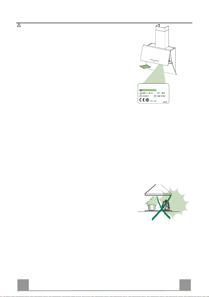
• Check that the mains voltage corresponds to that indicated on the
rating plate fixed to the inside of the hood.
• For Class I appliances, check that the domestic power supply guarantees adequate earthing.
Connect the extr actor to the exhaust fl ue through a pipe of mini mum
diameter 120 mm. The route of the flue must be as short as possible.
• Do not connect the extractor hood to exhaust ducts c arrying combus tion fumes (boilers, fireplaces, etc.).
• If the extractor is used in conj unction with non-electrical appliances
(e.g. gas burning appliances), a suffici ent degree of aeration must be
guaranteed in the room in order to prevent the backflow of exhaust
gas. The kitchen must have an opening communicating directl y with
the open air in order to guarantee the entry of clean air.
USE
• The extractor hood has been designed excl usi vely for domes tic use to
eliminate kitchen smells.
• Never use the hood for purposes other th an for which it has ben designed.
• Never leave high naked flames under the hood when it is in operation.
• Adjust the flame intensity to direct it onto the bottom of the pan only,
making sure that it does not engulf the sides.
• Deep fat fryers must be continuously monitored during use: overheated oil can burst into flames.
• Do not flambè under the range hood; risk of fire
• This appliance is not intended for use by persons (i ncluding children )
with reduced physical, sensory or mental capabilities, or lack of experience and knowledge, unles s they have been given supe rvision or
instruction concerning use of the appliance by a person respons ible
for their safety.
• Children should be supervised to ens ure that they do n ot pl ay wi th the
appliance.
MAINTENANCE
• Switch off or unplug the appliance from the mains supply before carrying out any maintenance work.
• Clean and/or replace the Filters after the specified time period.
• Clean the hood using a damp cloth and a neutral liquid detergent.
EN 118
CHARACTERISTICS
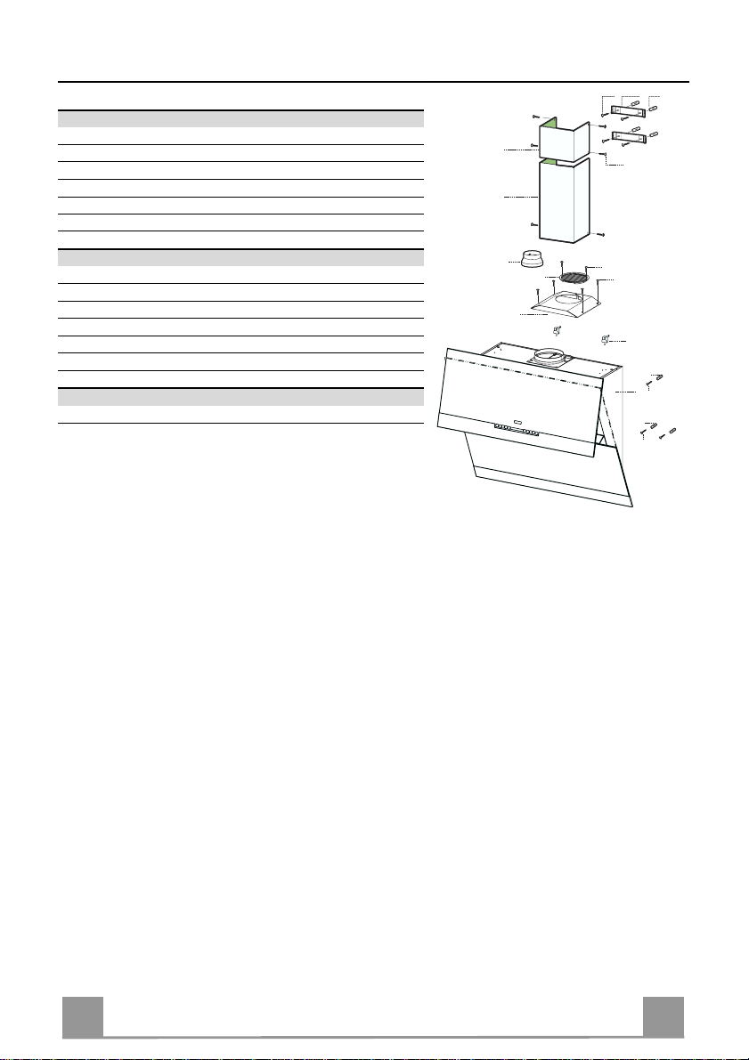
Components
Ref. Q.ty Product components
1 1 Cooker hood with control unit, lights, blower unit, fi lters
2.1 1 Upper chimney
2.2 1 Lower chimney
8 1 Air outlet grid
9 1 Reducer flan ge Ø 150-120
16 1 Cover for recycling version
Ref. Q.ty Installation components
7.2.1 2 Fixing brackets for upper chimney
11 7 Plugs
11a 2 Plugs SB 12/10
12a 7 Screws 4,2 x 44,4
12c 10 Screws 2,9 x 6, 5
12e 2 Screws 2,9 x 9,5
Q.ty Documentation
1 Instruction booklet
12a
7.2.1 11
2.1
2.2
9
8
16
12c
12d
12c
11a
11
1
12a
11
12a
 Loading...