

GB
IT
FR
DE
TR
SE
Instructions for use and installation
Cooker Hood
Istruzioni per l’uso e l’installazione
Cappa
Mode d’emploi et installation
Hotte de Cuisine
Bedienungsanleitung und Installation
Dunstabzugshaube
Kullanım ve montaj talimatları
Davlumbaz
Handbok för installation, användning och underhăll
Spisfläkt
ﻲﺑﺮﻋ
لﺎﻤﻌﺘــﺳﻹاو ﺐــﻴآﺮﺘﻟا تﺎﻤﻴﻠﻌﺗ
ﺔـــﻨﺧﺪﻣ
FMA 605 BK – FMA 805 BK – FMA 905 BK
FMA 605 WH – FMA 805 WH – FMA 905 WH
FMA 805 BK XS – FMA 805 WH XS
FMA 905 BK – BARBIERI – FMA 605 PG
FMA 805 PG – FMA 905 PG
FMA 605 DG – FMA 805DG – FMA 905 DG

INDEX
RECOMMENDATIONS AND SUGGESTIONS ..................................................................................................................... 4
CHARACTERISTICS ............................................................................................................................................................. 7
INSTALLATION...................................................................................................................................................................... 8
USE...................................................................................................................................................................................... 11
MAINTENANCE................................................................................................................................................................... 12
EN
INDICE
CONSIGLI E SUGGERIMENTI............................................................................................................................................ 14
CARATTERISTICHE............................................................................................................................................................ 17
INSTALLAZIONE ................................................................................................................................................................. 18
USO...................................................................................................................................................................................... 21
MANUTENZIONE ................................................................................................................................................................ 22
IT
SOMMAIRE
CONSEILS ET SUGGESTIONS.......................................................................................................................................... 24
CARACTERISTIQUES......................................................................................................................................................... 27
INSTALLATION.................................................................................................................................................................... 28
UTILISATION .......................................................................................................................................................................31
ENTRETIEN......................................................................................................................................................................... 32
FR
INHALTSVERZEICHNIS
EMPFEHLUNGEN UND HINWEISE ................................................................................................................................... 34
CHARAKTERISTIKEN......................................................................................................................................................... 37
MONTAGE ...........................................................................................................................................................................38
BEDIENUNG........................................................................................................................................................................ 41
WARTUNG........................................................................................................................................................................... 42
DE
IÇERIKLER
TAVSIYELER VE ÖNERILER.............................................................................................................................................. 44
ÖZELLIKLER........................................................................................................................................................................ 47
MONTAJ............................................................................................................................................................................... 48
KULLANIM ........................................................................................................................................................................... 51
BAKIM .................................................................................................................................................................................. 52
TR
INNEHÅLL
REKOMMENDATIONER OCH TIPS ...................................................................................................................................54
EGENSKAPER..................................................................................................................................................................... 57
INSTALLATION.................................................................................................................................................................... 58
ANVÄNDING........................................................................................................................................................................ 61
UNDERHÅLL........................................................................................................................................................................ 62
SE
2
2

سﺮﻬﻔﻟا
تادﺎﺷرا و تﺎﺣاﺮﺘﻗا.............................................................................................................................................. 64
ﺺﺋﺎﺼﺨﻟا...........................................................................................................................................................67
ﺐﻴآﺮﺘﻟا.............................................................................................................................................................68
ماﺪﺨﺘﺳﻻا.............................................................................................................................................................71
ﺔﻴﻠﻤﻋ ﺔﻧﺎﻴﺼﻟا....................................................................................................................................................72
SA
3
3
RECOMMENDATIONS AND SUGGESTIONS
The Instructions for Use apply to several versions of this appliance.
Accordingly, you may find descriptions of individual features that do not
apply to your specific appliance.
INSTALLATION
• The manufacturer will not be held liable for any damages resulting from
incorrect or improper installation.
• The minimum safety distance between the cooker top
and the extractor hood is 650 mm (some models can
be installed at a lower height, please refer to the
paragraphs on working dimensions and installation).
• Check that the mains voltage corresponds to that
indicated on the rating plate fixed to the inside of the
hood.
• For Class I appliances, check that the domestic
power supply guarantees adequate earthing.
Connect the extractor to the exhaust flue through a pipe of minimum
diameter 120 mm. The route of the flue must be as short as possible.
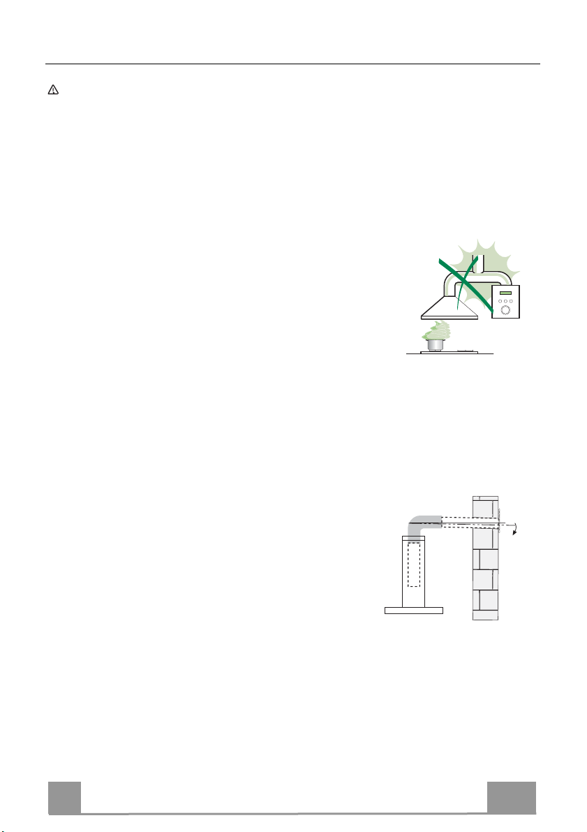
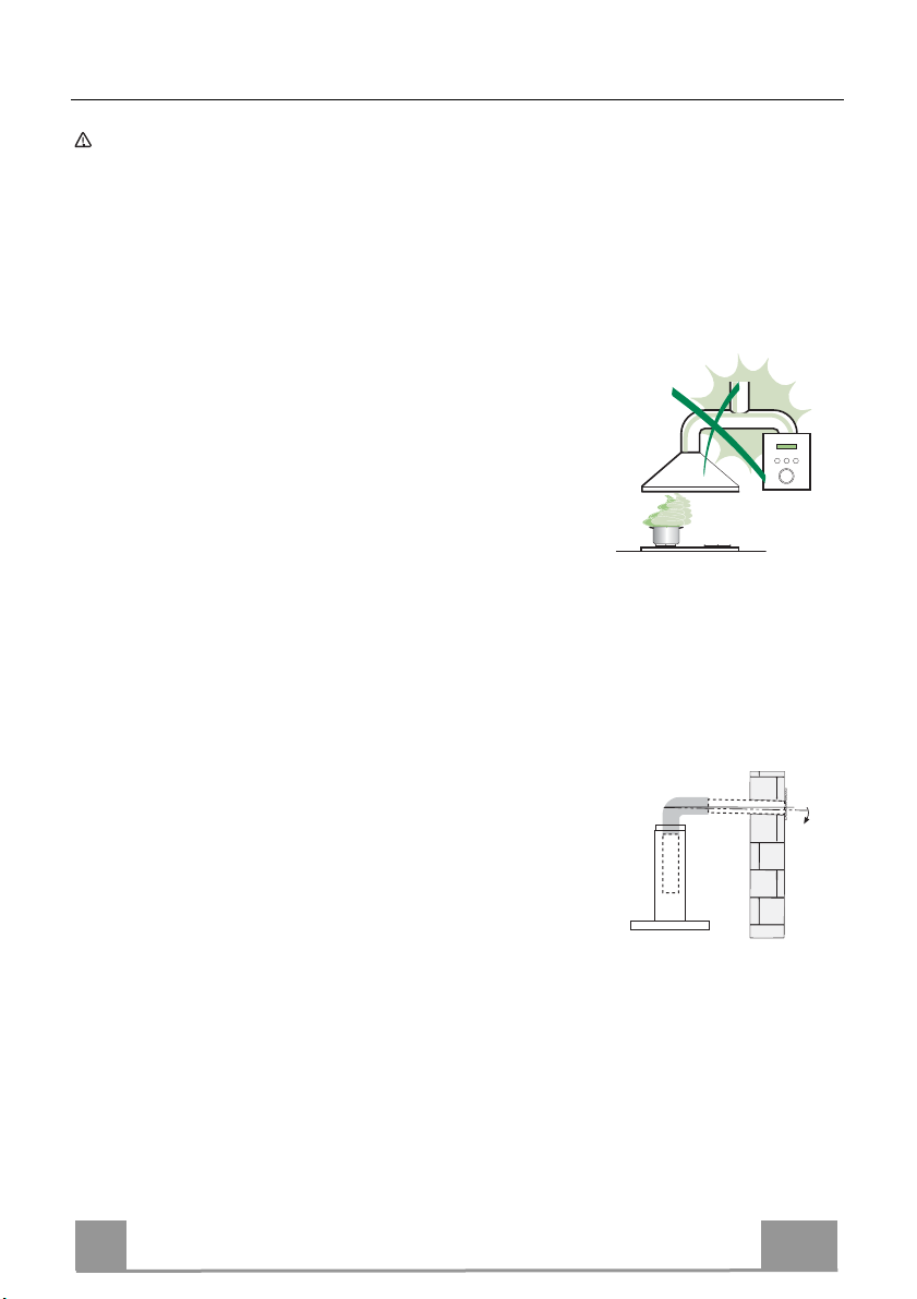
• Do not connect the extractor hood to exhaust ducts carrying combustion
fumes (boilers, fireplaces, etc.).
• If the extractor is used in conjunction with nonelectrical appliances (e.g. gas burning
appliances), a sufficient degree of aeration must
be guaranteed in the room in order to prevent the
backflow of exhaust gas. The kitchen must have
an opening communicating directly with the open
air in order to guarantee the entry of clean air.
When the cooker hood is used in conjunction with
appliances supplied with energy other than electric, the negative pressure in
the room must not exceed 0,04 mbar to prevent fumes being drawn back
into the room by the cooker hood.
• In the event of damage to the power cable, it must be replaced by the
manufacturer or by the technical service department, in order to prevent any
risks.
2°
EN
4
4

• If the instructions for installation for the gas hob specify a greater distance
specified above, this has to be taken into account. Regulations concerning
the discharge of air have to be fulfilled.
• Use only screws and small parts in support of the hood.
Warning: Failure to install the screws or fixing device in accordance with
these instructions may result in electrical hazards.
• Connect the hood to the mains through a two-pole switch having a contact
gap of at least 3 mm.
USE
• The extractor hood has been designed exclusively for domestic use to
eliminate kitchen smells.
• Never use the hood for purposes other than for which it has been designed.
• Never leave high naked flames under the hood when it is in operation.
• Adjust the flame intensity to direct it onto the bottom of the pan only, making
sure that it does not engulf the sides.
• Deep fat fryers must be continuously monitored
during use: overheated oil can burst into flames.
• Do not flambè under the range hood; risk of fire.
• This appliance can be used by children aged from
8 years and above and persons with reduced
physical, sensory or mental capabilities or lack of
experience and knowledge if they have been given supervision or instruction
concerning use of the appliance in a safe way and understand the hazards
involved. Children shall not play with the appliance. Cleaning and user
maintenance shall not be made by children without supervision.
EN
5
5
• “CAUTION: Accessible parts may become hot when used with cooking
appliances.”
MAINTENANCE
• Switch off or unplug the appliance from the mains supply before carrying out
any maintenance work.
• Clean and/or replace the Filters after the specified time period (Fire hazard).
• The Grease filters must be cleaned every 2 months of operation, or more
frequently for particularly heavy usage, and can be washed in a dishwasher.
• The Activated charcoal filter is not washable and cannot be regenerated,
and must be replaced approximately every 4 months of operation, or more
frequently for particularly heavy usage.
• Clean the hood using a damp cloth and a neutral liquid detergent.
The symbol on the product or on its packaging indicates that this product
may not be treated as household waste. Instead it shall be handed over to the
applicable collection point for the recycling of electrical and electronic
equipment. By ensuring this product is disposed of correctly, you will help
prevent potential negative consequences for the environment and human
health, which could otherwise be caused by inappropriate waste handling of
this product. For more detailed information about recycling of this product,
please contact your local city office, your household waste disposal service or
the shop where you purchased the product.
EN
6
6
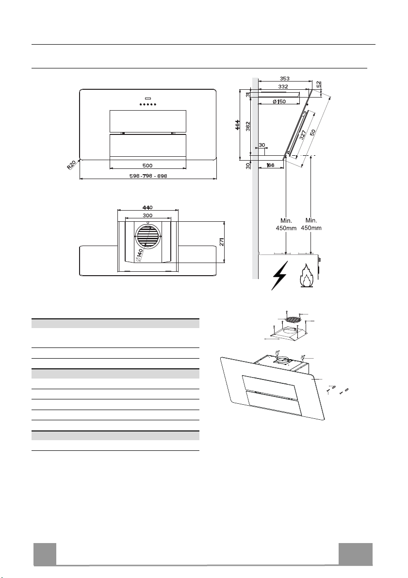
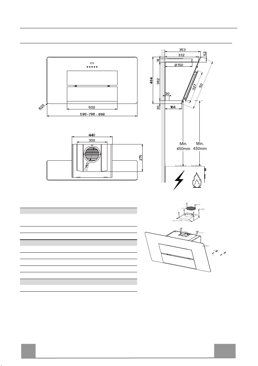
CHARACTERISTICS
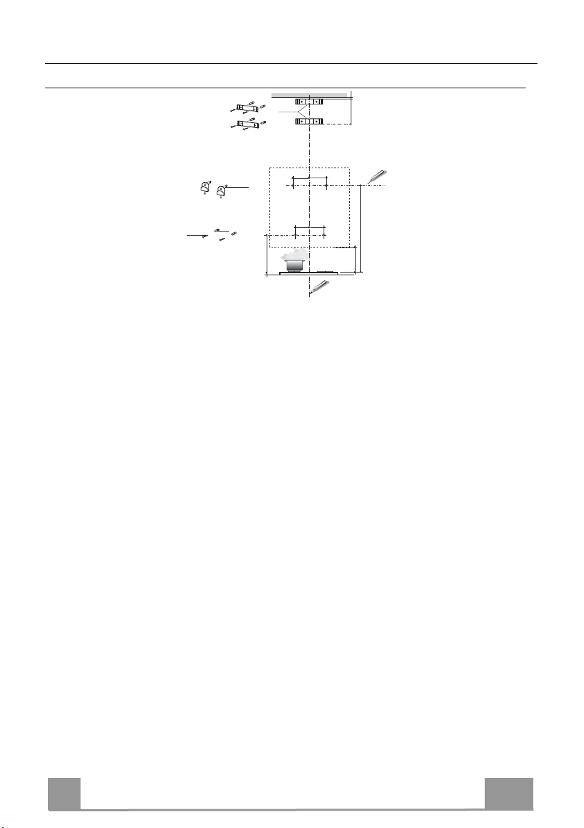
Dimensions
Components
Ref. Q.ty Product Components
1 1 Hood Body, complete with: Controls, Light,
Blower, Filters
8 1 Directional Air Outlet grille
16 1 Filter cover
Ref. Q.ty Installation Components
11 2 Wall Plugs
11a 2 Wall Plugs SB 12/10
12a 2 Screws 4,2 x 44,4
12c 4 Screws 2,9 x 6,5
12d 2 Screws 2,9 x 9,5
Q.ty Documentation
1 Instruction Manual
12d
8
16
12c
11a
1
11
12a
EN
7
7
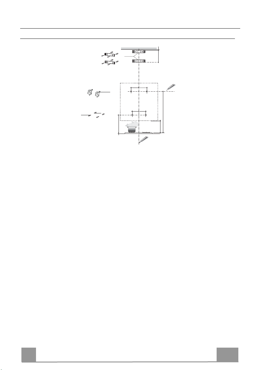
INSTALLATION
Wall drilling and bracket fixing
7.2.1
164 164
1
140
22
540
12a
11a
11
As a first step, proceed with the following drawings:
• a vertical line up to the ceiling or up to the upper limit, at the centre of the area in which the
hood is to be fitted;
• a horizontal line at a minimum 788 mm above the cooker top.
• Mark a point (1) on the horizontal line, 164 mm to the right of the vertical reference line.
• Repeat this operation on the other side, checking that the two marks are levelled.
• Mark a reference point (2) as indicated at 140 mm from the vertical reference line and 540
mm above the cooker top.
• Repeat this operation on the other side, checking that the two marks are levelled.
• Drill at the marked points (1), using a ø 12 mm drill bit.
• Drill at the marked points (2) using a ø 8 mm drill bit.
• Insert the bracket plugs 11a into the holes (1) and tighten the screws.
• Insert plug 11 into holes (2).
To install a decorative chimney ( optional )
• Place bracket 7.2.1 on the wall, about 1-2 mm from the ceiling or from the upper limit,
aligning the centre (notch) with the vertical reference line.
• Mark the wall at the centres of the bracket holes.
• Place the bracket 7.2.1 on the wall at X mm below the first bracket (X = height of the upper
chimney section), aligning the centre (notch) with the vertical line.
• Mark the wall at the centres of the bracket holes.
• Drill ø 8 mm holes at all the marked centre points.
• Insert the wall plugs 11 in the holes.
• Fix the brackets using the 12a screws (4,2 x 44,4) supplied with the hood.
1÷2
X
1
140
788
450
EN
8
8

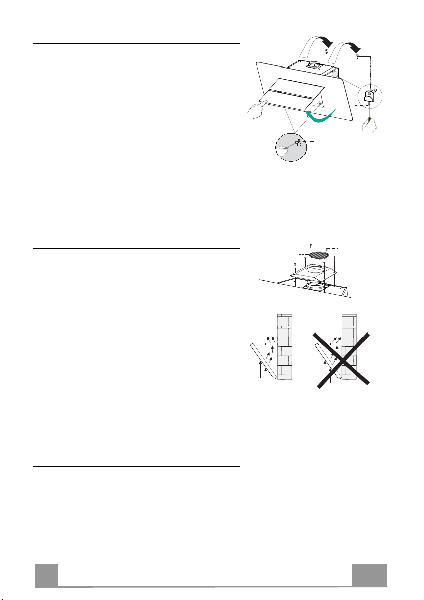
Fitting the hood body
• Open the doors/the door (See section Open Panels).
• Remove the Metal grease filters using the handles
provided.
• Adjust the two screws Vr, in the brackets 11a, so that
they are at the start of their travel.
• Hook the hood body to the two brackets 11a.
• From the inside of the hood body, turn screws Vr to
level the hood body itself.
• Fasten the safety screw 12a.
• Close the doors/the door again.
11a
Vr
12a
Air outlet – Recirculation Version
• Screw the filter cover onto the air outlet, using four
screws 12c (2.9 x 6.5).
• Fix the directional Grid 8 on the recycled air outlet,
using 2 screws 12d (2.9 x 9.5) provided.
• Open the Door/Doors (See paragraph Opening
Panels).
• Remove the Metal grease filters using the handles
provided.
• Make sure that the Activated charcoal odour filter
has been fitted.
Connections
AIR OUTLET - DUCTING VERSION
To install the hood in the ducting version, please refer
to the instructions provided in the ducting kit specific to
the hood.
8
16
12d
12c
EN
9
9

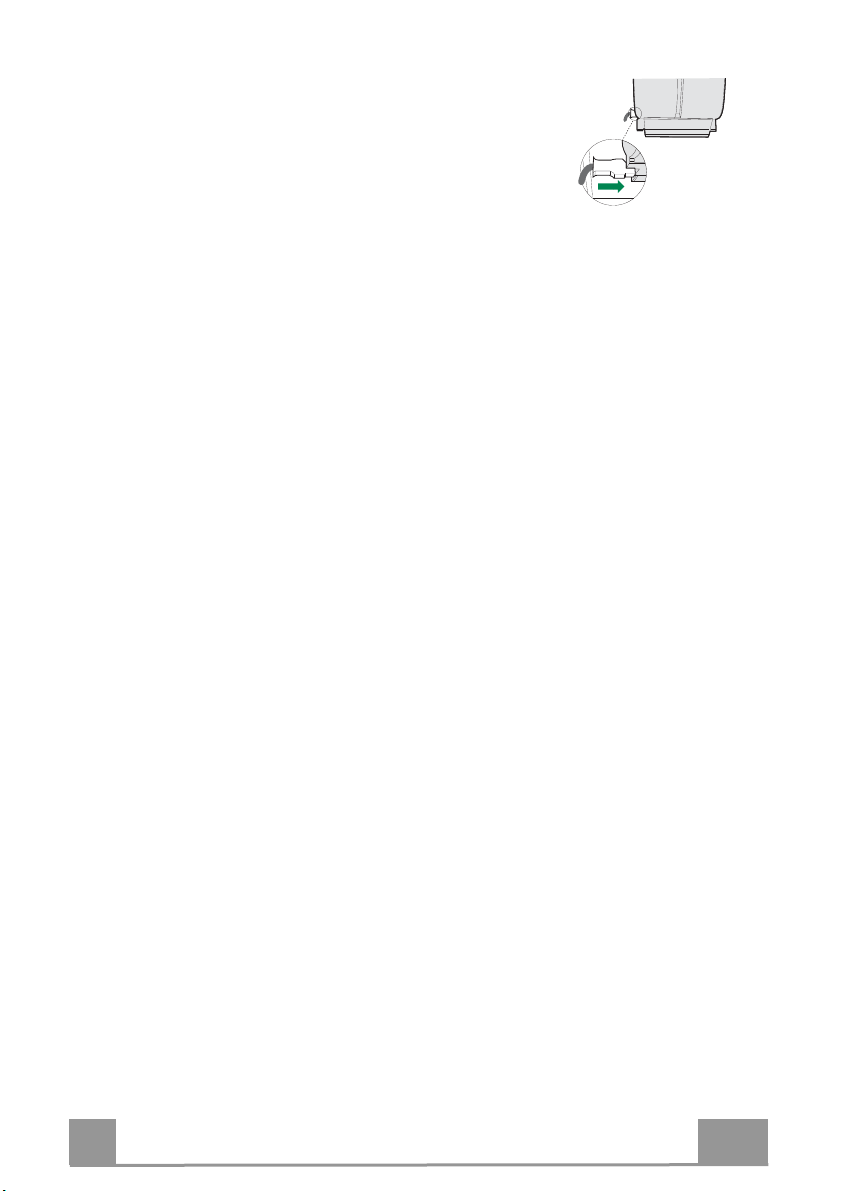
ELECTRICAL CONNECTION
• Connect the hood to the mains through a two-pole switch having a contact gap of at least 3 mm.
• Remove the grease filters (see paragraph Maintenance) being
sure that the connector of the feeding cable is correctly inserted
in the socket placed on the side of the fan.
EN
10
1

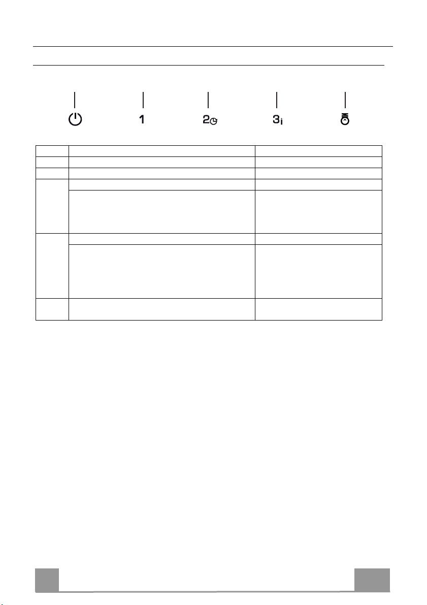
USE
T1 T2 T3 T4 L
Button Function
T1
T2
T3
T4
Turns the Motor off.
Turns the motor on at speed one Buttons T1+T2 are lit.
Turns the Motor on at speed two Buttons T1+T3 are lit.
Press and hold for 2 seconds to activate
switch-off with a 30 minute delay (Motor+Lights). It is possible to change the operating speed with this function activated.
Turns the Motor on at speed three Buttons T1+T4 are lit.
Press and hold for 2 seconds to activate Intensive speed with a timer set to 6 minutes,
after which it returns to the speed that was
set previously. Suitable to deal with maximum levels of cooking fumes.
Turns the Lighting system on and off at
L
maximum intensity.
Control panel
Buttons T1+ (T2 or T3 or T4,
respectively) flash.
The Button flashes.
Button on
EN
11
1
MAINTENANCE
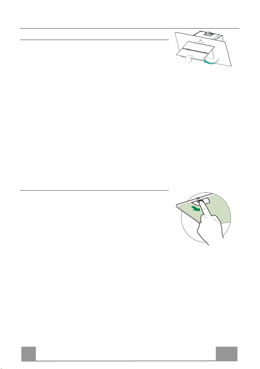
Opening Panel
• Open the Panel by pulling it.
• The panel can be locked in any position.
• Clean the outside with a damp cloth and neutral detergent.
• Clean the inside using a damp cloth and neutral detergent; do
not use wet cloths or sponges, or jets of water; do not use
abrasive substances.
Grease filters
CLEANING METAL SELF- SUPPORTING GREASE FILTERS
• The filters must be cleaned every 2 months of operation, or
more frequently for particularly heavy usage, and can be
washed in a dishwasher.
• Pull the comfort panels to open them.
• Remove the filters one by one pushing them towards the back
side of the hood unit and simultaneously pulling downwards.
• Any kind of bending of the filters has to be avoided when
washing them. Before fitting them again into the hood make
sure that they are completely dry. (The colour of the filter surface may change throughout the time but this has no influence
to the filter efficiency).
• When fitting the filters into the hood pay attention that they are
mounted in correct position the handle facing outwards.
• Close the comfort panel.
EN
12
1
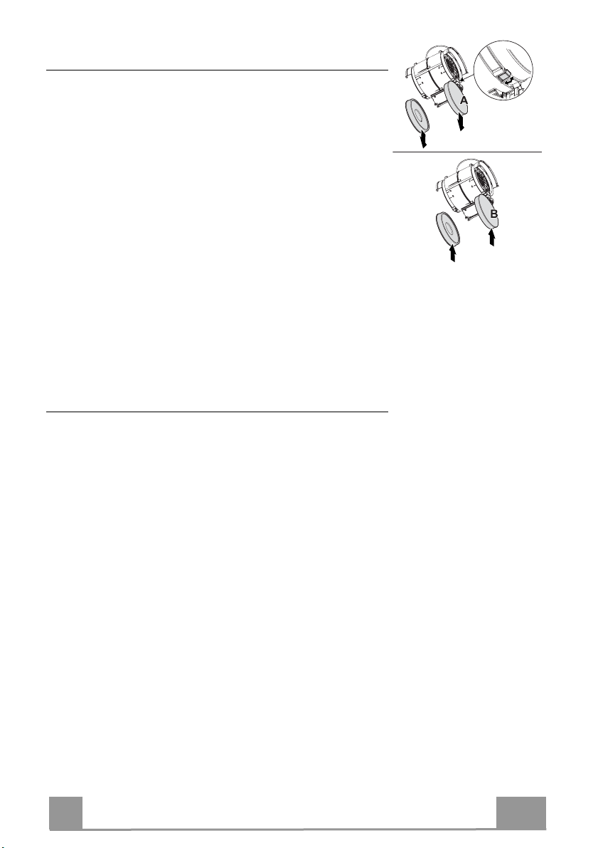
Activated charcoal filter (Recirculation version)
These filters are not washable and cannot be regenerated, and
must be replaced approximately every 4 months of operation, or
more frequently with heavy usage.
REPLACING THE ACTIVATED CHARCOAL FILTER
• Open the comfort panels pulling them downwards.
• Remove the metal grease filters
• Remove the saturated activated charcoal filter as shown (A).
• Fit the new filters (B).
• Replace the metal grease filters.
• Close the comfort panels.
Lighting unit
Warning: This appliance is fitted with a white LED lamp classed
as 1M according to EN 60825-1: 1994 + A1:2002 + A2:2001
standards; maximum optical power emitted @439nm: 7µW. Do
not look directly at the light through optical devices (binoculars,
magnifying glasses…).
• For replacement contact technical support. ("To purchase contact technical support")
EN
1
13
CONSIGLI E SUGGERIMENTI
Le Istruzioni per l’uso si riferiscono ai diversi modelli di questo
apparecchio. Pertanto, si potrebbero trovare descrizioni di singole
caratteristiche che non appartengono al proprio apparecchio specifico.
INSTALLAZIONE
• Il fabbricante non potrà ritenersi responsabile per eventuali danni risultanti
da un’installazione o utilizzazione impropria.
• La distanza minima di sicurezza tra il piano cottura
e la cappa aspirante è di 650 mm (alcuni modelli
possono essere installati a un’altezza inferiore;
vedere il paragrafo relativo alle dimensioni di lavoro
e all'installazione).
• Controllare che la tensione di rete corrisponda a
quella indicata sulla targa dati applicata all’interno
della cappa.
• Per gli apparecchi di Classe I, controllare che la rete di alimentazione
domestica disponga di un adeguato collegamento a massa.
Collegare l'aspiratore al condotto dei fumi mediante un tubo con diametro
minimo di 120 mm. Il percorso dei fumi deve essere il più corto possibile.
• Non collegare la cappa aspirante ai condotti fumari che trasportano fumi di
combustione (per es. caldaie, camini ecc.).
• Se l’aspiratore è utilizzato in combinazione con
apparecchi non elettrici (per es. apparecchi a gas),
deve essere garantito un sufficiente grado di
aerazione nel locale per impedire il ritorno di flusso
dei gas di scarico. La cucina deve avere un'apertura
comunicante direttamente con l'esterno per garantire
l'afflusso di aria pulita. Quando la cappa per cucina è utilizzata in
combinazione con apparecchi non alimentati dalla corrente elettrica, la
pressione negativa nel locale non deve superare 0,04 mbar per evitare che i
fumi vengano riaspirati nel locale dalla cappa.
• In caso di danneggiamento del cavo di alimentazione, occorre farlo sostituire
dal produttore o dal reparto di assistenza tecnica per evitare qualsiasi
rischio.
2°
IT
14
1
• Se le istruzioni di installazione del piano cottura a gas specificano una
distanza maggiore di quella sopra indicata, è necessario tenerne conto.
Devono essere rispettate tutte le normative riguardanti lo scarico dell'aria.
• Usare solo viti e minuteria di tipo idoneo per la cappa.
Avvertenza: la mancata installazione delle viti o dei dispositivi di fissaggio in
conformità alle presenti istruzioni può comportare rischi di scosse elettriche.
• Collegare la cappa all'alimentazione di rete mediante un interruttore bipolare
con distanza tra i contatti di almeno 3 mm.
USO
• La cappa aspirante è progettata esclusivamente per l’uso domestico allo
scopo di eliminare gli odori dalla cucina.
• Non usare mai la cappa per scopi diversi da quelli per cui è stata progettata.
• Non lasciare mai fiamme alte sotto la cappa quando è in funzione.
• Regolare l'intensità della fiamma in modo da dirigerla esclusivamente verso
il fondo del recipiente di cottura, assicurandosi che non ne avvolga i lati.
• Le friggitrici devono essere costantemente
controllate durante l’uso: l’olio surriscaldato
potrebbe incendiarsi.
• Non cuocere al flambé sotto la cappa: si potrebbe
sviluppare un incendio.
• Questo apparecchio può essere utilizzato da
bambini di età non inferiore a 8 anni e da persone con ridotte capacità psicofisico-sensoriali o con esperienza e conoscenze insufficienti, purché
attentamente sorvegliati e istruiti su come utilizzare in modo sicuro
l'apparecchio e sui pericoli che ciò comporta. Assicurarsi che i bambini non
giochino con l'apparecchio. Pulizia e manutenzione da parte dell'utente non
devono essere effettuate da bambini, a meno che non siano sorvegliati.
IT
15
1
• “ATTENZIONE: le parti accessibili possono diventare molto calde durante
l’uso degli apparecchi di cottura”.
MANUTENZIONE
• Spegnere o scollegare l’apparecchio dalla rete di alimentazione prima di
qualunque operazione di pulizia o manutenzione.
• Pulire e/o sostituire i filtri dopo il periodo di tempo specificato (pericolo di
incendio).
• I filtri antigrasso devono essere puliti ogni 2 mesi di funzionamento o più
frequentemente in caso di utilizzo molto intenso e possono essere lavati in
lavastoviglie.
• Il filtro al carbone attivo non è lavabile né è rigenerabile e deve essere
sostituito ogni 4 mesi di funzionamento circa o più frequentemente in caso di
utilizzo molto intenso.
• Pulire la cappa utilizzando un panno umido e un detergente liquido neutro.
Il simbolo sul prodotto o sulla sua confezione indica che il prodotto non
può essere smaltito come un normale rifiuto domestico. Il prodotto da smaltire
deve essere conferito presso un apposito centro di raccolta per il riciclaggio
dei componenti elettrici ed elettronici. Assicurandosi che questo prodotto sia
smaltito correttamente, si contribuirà a prevenire potenziali conseguenze
negative per l’ambiente e per la salute che potrebbero altrimenti derivare dal
suo smaltimento inadeguato. Per informazioni più dettagliate sul riciclaggio di
questo prodotto, contattare il Comune, il servizio locale di smaltimento rifiuti
oppure il negozio dove è stato acquistato il prodotto.
IT
16
1
CARATTERISTICHE
Ingombro
Componenti
Rif. Q.tà Componenti di Prodotto
1 1 Corpo Cappa completo di: Comandi, Luce, Grup-
8 1 Griglia direzionata Uscita Aria
16 1 Coperchio filtrante
Rif. Q.tà Componenti di Installazione
11 2 Tasselli
11a 2 Tasselli SB 12/10
12a 2 Viti 4,2 x 44,4
12c 4 Viti 2,9 x 6,5
12d 2 Viti 2,9 x 9,5
Q.tà Documentazione
1 Libretto Istruzioni
po Ventilatore, Filtri
12d
8
16
12c
11a
1
11
12a
IT
17
1
INSTALLAZIONE
Foratura Parete e Fissaggio Staffe
12a
7.2.1
164 164
11a
11
1
140
140
22
1÷2
X
1
788
540
450
Tracciare sulla Parete:
• una linea Verticale fino al soffitto o al limite superiore, al centro della zona prevista per il
montaggio della Cappa;
• una linea Orizzontale a 788 mm min. sopra il Piano di Cottura.
• Segnare un punto (1) sulla linea orizzontale a 164 mm alla destra della linea verticale di riferimento.
• Ripetere questa operazione dalla parte opposta, verificandone il livellamento.
• Segnare come indicato, un punto di riferimento (2) a 140 mm dalla linea Verticale di riferimento, e 540 mm sopra il Piano di Cottura.
• Ripetere questa operazione dalla parte opposta, verificandone il livellamento.
• Forare ø 12 mm i punti (1) segnati.
• Forare ø 8 mm i punti (2) segnati.
• Inserire i tasselli con staffa 11a nei fori (1) e avvitare.
• Inserire il tassello 11 nei fori (2).
Per installazione con camino decorativo: (Opzionale)
• Appoggiare come indicato la Staffa 7.2.1 a 1-2 mm dal soffitto o dal limite superiore, allineando il suo centro (intagli) sulla linea Verticale di riferimento.
• Segnare i centri dei Fori della Staffa.
• Appoggiare come indicato la Staffa 7.2.1 a X mm sotto la prima staffa (X = altezza Camino
Superiore in dotazione), allineando il suo centro (intagli) sulla linea Verticale di riferimento.
• Segnare i centri dei Fori della Staffa.
• Forare ø 8 mm i punti segnati.
• Inserire i tasselli 11 nei fori.
• Fissare le Staffe utilizzando le Viti 12a (4,2 x 44,4) in dotazione.
IT
18
1
Montaggio Corpo Cappa
• Aprire le Ante/l’Anta (Vedi paragrafo Apertura Pannelli).
• Togliere i Filtri Antigrasso agendo sulle apposite
maniglie.
• Regolare le due viti Vr, delle staffe 11a, ad inizio
corsa.
• Agganciare il corpo cappa alle 2 staffe 11a.
• Dall’interno del corpo cappa agire sulle Viti Vr per
livellare il Corpo Cappa.
• Avvitare la vite di sicurezza 12a.
• Richiudere le Ante/l’Anta.
11a
Vr
12a
Uscita aria Versione Filtrante
• Avvitare il coperchio filtrante sull’uscita aria, utilizzando quattro viti 12c (2,9 x 6,5).
• Fissare la Griglia direzionata 8 sull’uscita dell’aria
riciclata con 2 Viti 12d (2,9 x 9,5) in dotazione.
• Aprire le Ante/l’Anta (Vedi paragrafo Apertura Pannelli).
• Togliere i Filtri Antigrasso agendo sulle apposite
maniglie.
• Assicurarsi della presenza dei Filtri antiodore al Carbone attivo.
Connessioni
USCITA ARIA VERSIONE ASPIRANTE
Per l’installazione della Cappa in versione Aspirante
fare riferimento alle istruzioni contenute nel Kit aspirante specifico per la Cappa.
8
16
12d
12c
IT
19
1
CONNESSIONE ELETTRICA
• Collegare la Cappa all’Alimentazione di Rete interponendo un
Interruttore bipolare con apertura dei contatti di almeno 3 mm.
• Rimuovere i Filtri antigrasso (vedi par. “Manutenzione”) e assicurarsi che il connettore del Cavo di alimentazione sia correttamente inserito nella presa dell’Aspiratore
IT
20
2
USO
Quadro comandi
T1 T2 T3 T4 L
Tasto Funzione
Spegne il Motore. -
T1
Accende il motore alla prima velocità I Tasti T1+T2 sono accesi.
T2
Accende il motore alla seconda velocità I Tasti T1+T3 sono accesi.
T3
Premuto per 2 secondi attiva lo spegnimento
ritardato di 30 minuti (Motore+Luci). A funzione attiva è possibile cambiare la velocità di
esercizio.
Accende il motore alla terza velocità I Tasti T1+T4 sono accesi.
T4
Premuto per 2 Secondi attiva la velocità Intensiva temporizzata a 6 minuti, al termine dei
quali ritorna alla velocità precedentemente impostata. Adatta a fronteggiare le massime emissioni di fumi di cottura.
Accende e spegne l’Impianto di Illuminazione
L
alla massima intensità.
I rispettivi tasti T1+ (T2 o T3
o T4) Lampeggiano.
Il Tasto lampeggia.
Tasto acceso
IT
21
2

MANUTENZIONE
Apertura Pannello
• Aprire il Pannello tirandolo.
• Il pannello si bloccherà in qualsiasi posizione si metta.
• Pulirlo esternamente con un panno umido e detersivo liquido
neutro.
• Pulirlo anche internamente utilizzando un panno umido e detergente neutro; non utilizzare panni o spugne bagnate, né getti
d’acqua; non utilizzare sostanze abrasive.
Filtri antigrasso
PULIZIA FILTRI ANTIGRASSO METALLICI AUTOPORTANTI
• Sono lavabili anche in lavastoviglie, e necessitano di essere
lavati ogni 2 mesi circa di utilizzo o più frequentemente, per un
uso particolarmente intenso.
• Aprire i Comfort Panel tirandoli.
• Togliere i Filtri uno alla volta, spingendoli verso la parte posteriore del gruppo e tirando contemporaneamente verso il basso.
• Lavare i Filtri evitando di piegarli, e lasciarli asciugare prima
di rimontarli. (Un eventuale cambiamento del colore della superficie del filtro, che potrebbe verificarsi nel tempo, non pregiudica assolutamente l’efficienza dello stesso.)
• Rimontarli facendo attenzione a mantenere la maniglia verso la
parte visibile esterna.
• Richiudere i comfort panel.
IT
22
2

Filtri antiodore al Carbone attivo (Versione Filtrante)
Il Filtro antiodore al Carbone attivo non è lavabile e non è rigenerabile, va sostituito ogni 4 mesi circa di utilizzo o più frequentemente, per un uso particolarmente intenso.
SOSTITUZIONE
• Aprire i Comfort Panel tirandoli.
• Togliere i Filtri antigrasso.
• Rimuovere i Filtri antiodore al Carbone attivo saturi, come indicato (A).
• Montare i nuovi Filtri, come indicato (B).
• Rimontare i Filtri antigrasso.
• Richiudere i Comfort Panel.
Illuminazione
Attenzione: Questo apparecchio è provvisto di una luce LED
bianca di classe 1M secondo la norma EN 60825-1: 1994 +
A1:2002 + A2:2001; massima potenza ottica emessa@439nm:
7µW. Non osservare direttamente con strumenti ottici (binocolo,
lente d’ingrandimento….).
• Per la sostituzione contattare l’Assistenza Tecnica. ("Per l'acquisto rivolgersi all'assistenza tecnica").
IT
2
23
 Loading...