

Page 1

Instructions for use and installation
GB
Cooker Hood
Istruzioni per l’uso e l’installazione
IT
Cappa
Mode d’emploi et installation
FR
Hotte de Cuisine
Bedienungsanleitung und Installation
DE
Dunstabzugshaube
Kullanım ve montaj talimatları
TR
Davlumbaz
Instrukcja obsługi i instalacji
PL
Okap kuchenny
FLI 605 XS LED
FLI 705 XS LED
FLI 905 XS LED
Page 2

INDEX
RECOMMENDATIONS AND SUGGESTIONS ..................................................................................................................... 3
CHARACTERISTICS ............................................................................................................................................................. 6
INSTALLATION...................................................................................................................................................................... 7
USE ...................................................................................................................................................................................... 10
MAINTENANCE................................................................................................................................................................... 11
EN
INDICE
CONSIGLI E SUGGERIMENTI............................................................................................................................................ 12
CARATTERISTICHE............................................................................................................................................................ 15
INSTALLAZIONE ................................................................................................................................................................. 16
USO...................................................................................................................................................................................... 19
MANUTENZIONE ................................................................................................................................................................ 20
SOMMAIRE
CONSEILS ET SUGGESTIONS.......................................................................................................................................... 21
CARACTERISTIQUES......................................................................................................................................................... 24
INSTALLATION.................................................................................................................................................................... 25
UTILISATION .......................................................................................................................................................................28
ENTRETIEN......................................................................................................................................................................... 29
INHALTSVERZEICHNIS
EMPFEHLUNGEN UND HINWEISE ................................................................................................................................... 30
CHARAKTERISTIKEN......................................................................................................................................................... 33
MONTAGE ...........................................................................................................................................................................34
BEDIENUNG........................................................................................................................................................................ 37
WARTUNG........................................................................................................................................................................... 38
IÇERIKLER
TAVSİYELER VE ÖNERİLER.............................................................................................................................................. 39
ÖZELLIKLER........................................................................................................................................................................ 42
MONTAJ............................................................................................................................................................................... 43
KULLANIM ........................................................................................................................................................................... 46
BAKIM .................................................................................................................................................................................. 47
IT
FR
DE
TR
2
PL
2
SPIS TREŚCI
UWAGI I SUGESTIE............................................................................................................................................................ 48
WŁAŚCIWOŚCI TECHNICZNE........................................................................................................................................... 51
INSTALACJA........................................................................................................................................................................ 52
UŻYTKOWANIE................................................................................................................................................................... 55
KONSERWACJA ................................................................................................................................................................. 56
Page 3
RECOMMENDATIONS AND SUGGESTIONS
The Instructions for Use apply to several versions of this appliance.
Accordingly, you may find descriptions of individual features that do not
apply to your specific appliance.
INSTALLATION
• The manufacturer will not be held liable for any damages resulting from
incorrect or improper installation.
• The minimum safety distance between the cooker top and the extractor hood
is 650 mm (some models can be installed at a lower height, please refer to
the paragraphs on working dimensions and installation).
• Check that the mains voltage corresponds to that indicated on the rating
plate fixed to the inside of the hood.
• For Class I appliances, check that the domestic power supply guarantees
adequate earthing.
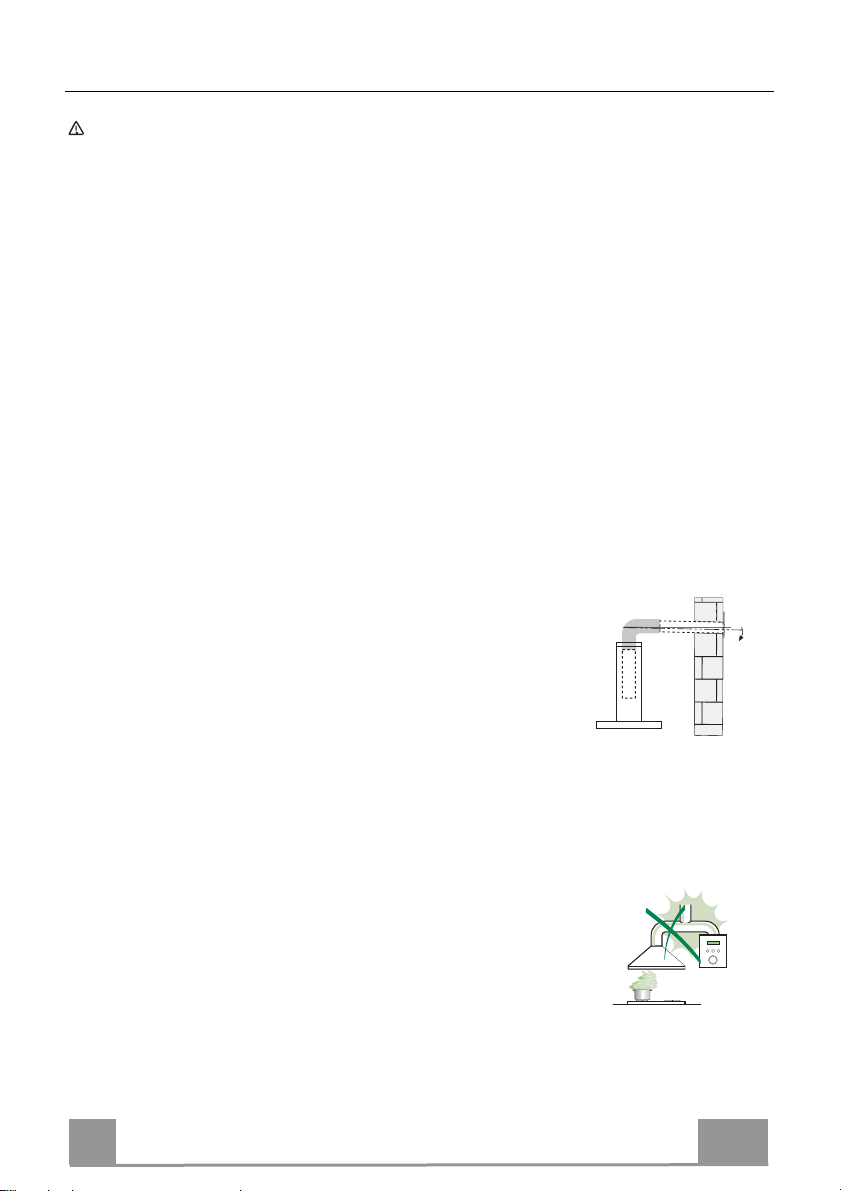
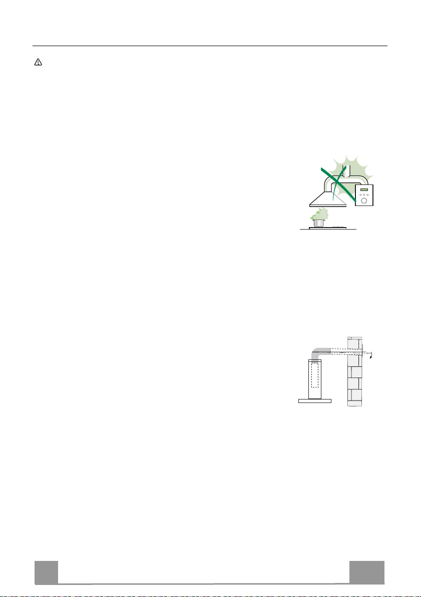
Connect the extractor to the exhaust flue through a pipe of minimum
diameter 120 mm. The route of the flue must be as short as possible.
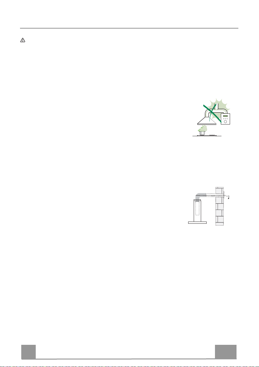
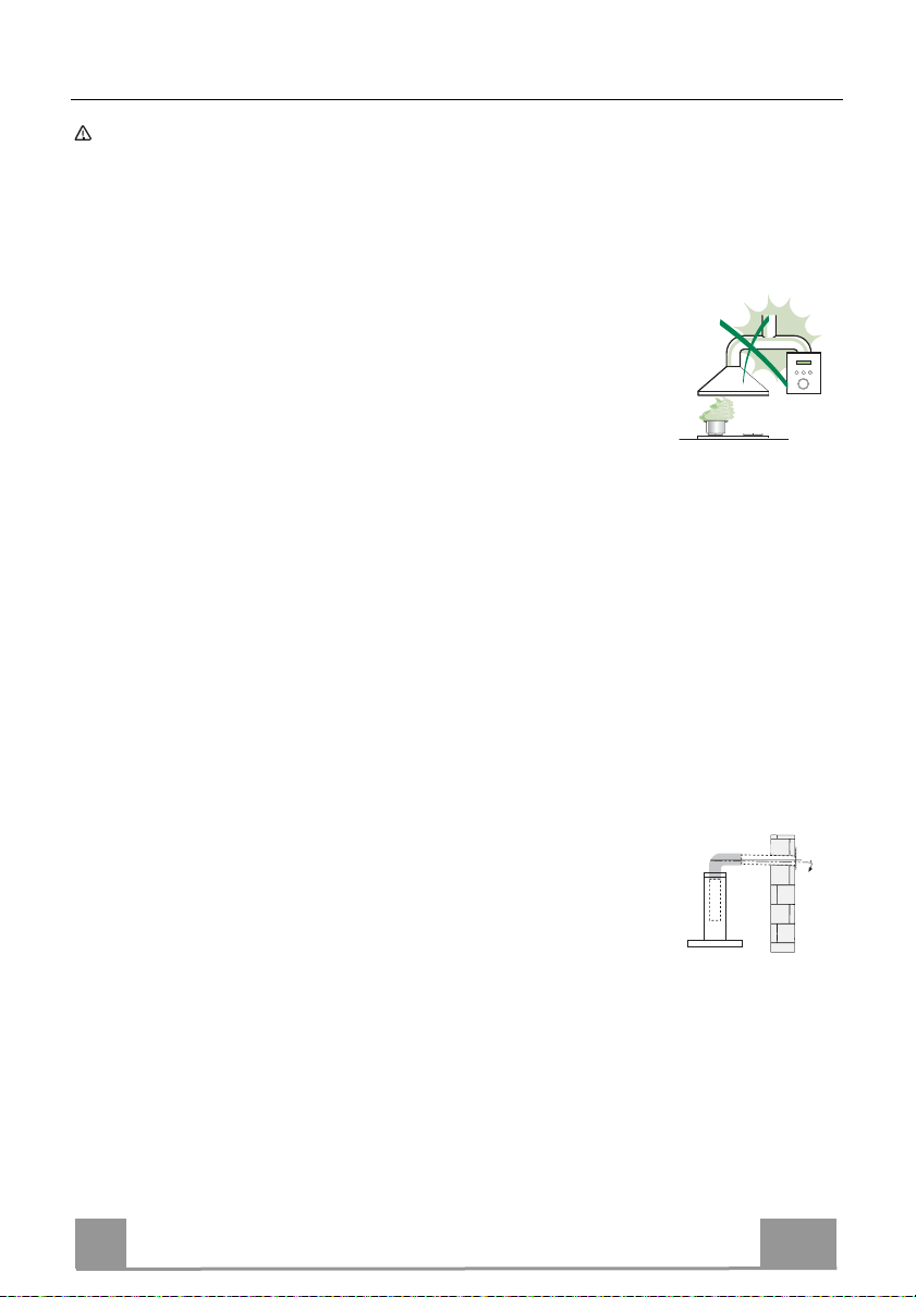
• Do not connect the extractor hood to exhaust ducts
carrying combustion fumes (boilers, fireplaces, etc.).
• If the extractor is used in conjunction with non-electrical
appliances (e.g. gas burning appliances), a sufficient
degree of aeration must be guaranteed in the room in
order to prevent the backflow of exhaust gas. The
kitchen must have an opening communicating directly
with the open air in order to guarantee the entry of clean air. When the
cooker hood is used in conjunction with appliances supplied with energy
other than electric, the negative pressure in the room must not exceed 0,04
mbar to prevent fumes being drawn back into the room by the cooker hood.
• The air must not be discharged into a flue that is used for
exhausting fumes from appliances burning gas or other
fuels (not applicable to appliances that only discharge the
air back into the room).
• In the event of damage to the power cable, it must be
replaced by the manufacturer or by the technical service
department, in order to prevent any risks.
2°
EN
3
3
Page 4
• If the instructions for installation for the gas hob specify a greater distance
specified above, this has to be taken into account. Regulations concerning
the discharge of air have to be fulfilled.
• Use only screws and small parts in support of the hood.
Warning: Failure to install the screws or fixing device in accordance with
these instructions may result in electrical hazards.
• Connect the hood to the mains through a two-pole switch having a contact
gap of at least 3 mm.
USE
• The extractor hood has been designed exclusively for domestic use to
eliminate kitchen smells.
• Never use the hood for purposes other than for which it has been designed.
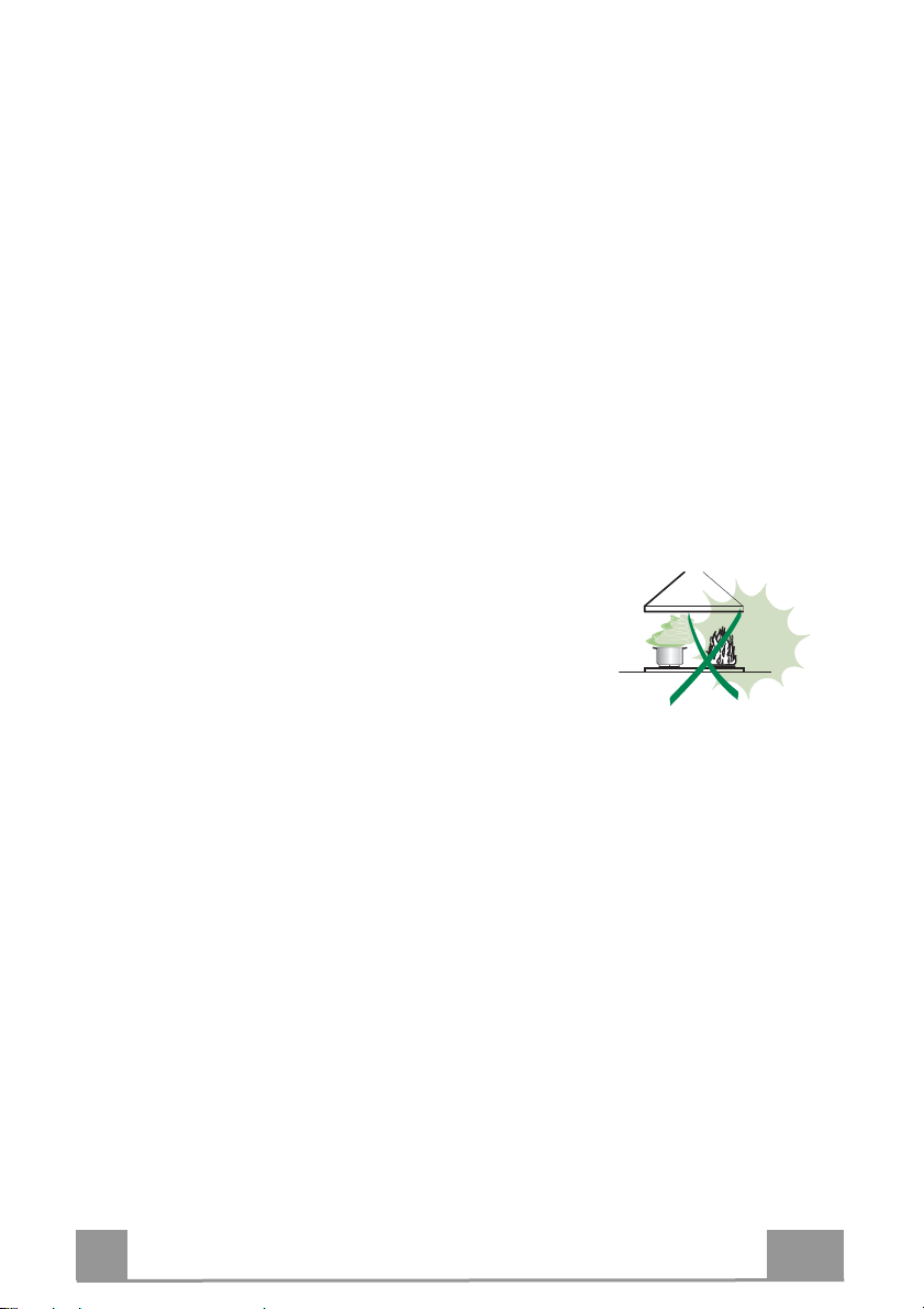
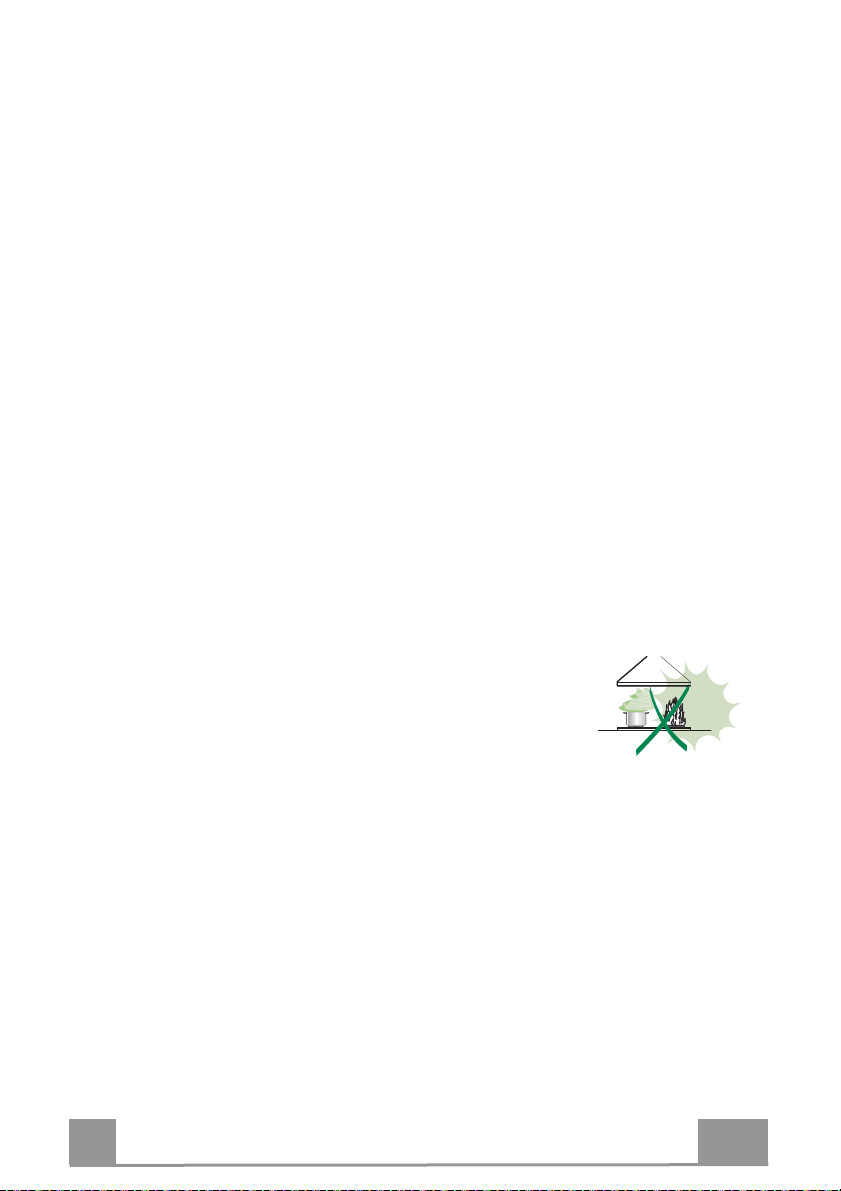
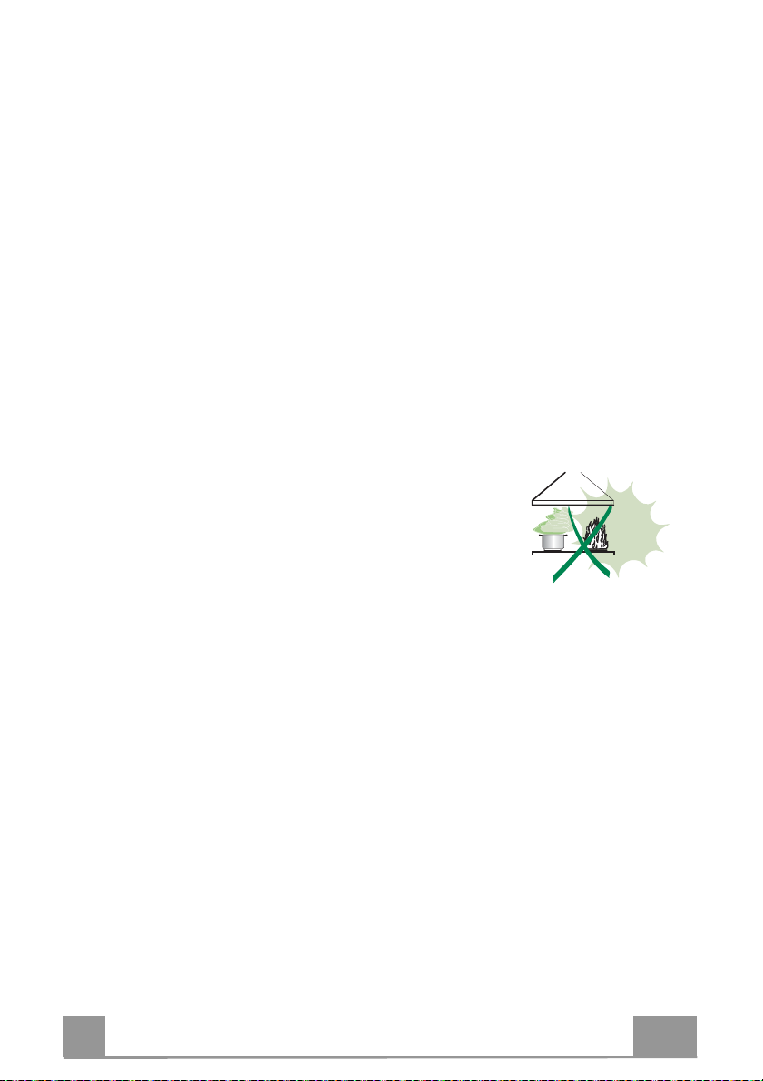
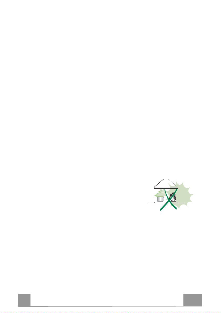
• Never leave high naked flames under the hood when it is in operation.
• Adjust the flame intensity to direct it onto the bottom of the pan only, making
sure that it does not engulf the sides.
• Deep fat fryers must be continuously monitored
during use: overheated oil can burst into flames.
• Do not flambè under the range hood; risk of fire.
• This appliance can be used by children aged from
8 years and above and persons with reduced
physical, sensory or mental capabilities or lack of
experience and knowledge if they have been given supervision or instruction
concerning use of the appliance in a safe way and understand the hazards
involved. Children shall not play with the appliance. Cleaning and user
maintenance shall not be made by children without supervision.
• This appliance is not intended for use by persons (including children) with
reduced physical, sensory or mental capabilities, or lack of experience and
knowledge, unless they have been given supervision or instruction
concerning use of the appliance by a person responsible for their safety.
EN
4
4
Page 5

• “CAUTION: Accessible parts may become hot when used with cooking
appliances.”
MAINTENANCE
• Switch off or unplug the appliance from the mains supply before carrying out
any maintenance work.
• Clean and/or replace the Filters after the specified time period (Fire hazard).
• The Grease filters must be cleaned every 2 months of operation, or more
frequently for particularly heavy usage, and can be washed in a dishwasher.
• The Activated charcoal filter is not washable and cannot be regenerated,
and must be replaced approximately every 4 months of operation, or more
frequently for particularly heavy usage.
• "Failure to carry out cleaning as indicated will result in a fire hazard".
• Clean the hood using a damp cloth and a neutral liquid detergent.
The symbol on the product or on its packaging indicates that this product
may not be treated as household waste. Instead it shall be handed over to the
applicable collection point for the recycling of electrical and electronic
equipment. By ensuring this product is disposed of correctly, you will help
prevent potential negative consequences for the environment and human
health, which could otherwise be caused by inappropriate waste handling of
this product. For more detailed information about recycling of this product,
please contact your local city office, your household waste disposal service or
the shop where you purchased the product.
EN
5
5
Page 6
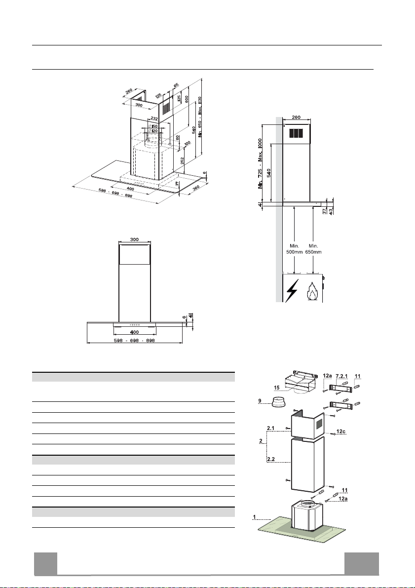
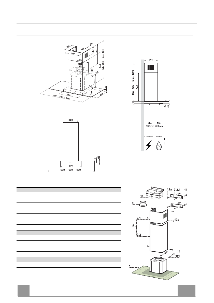
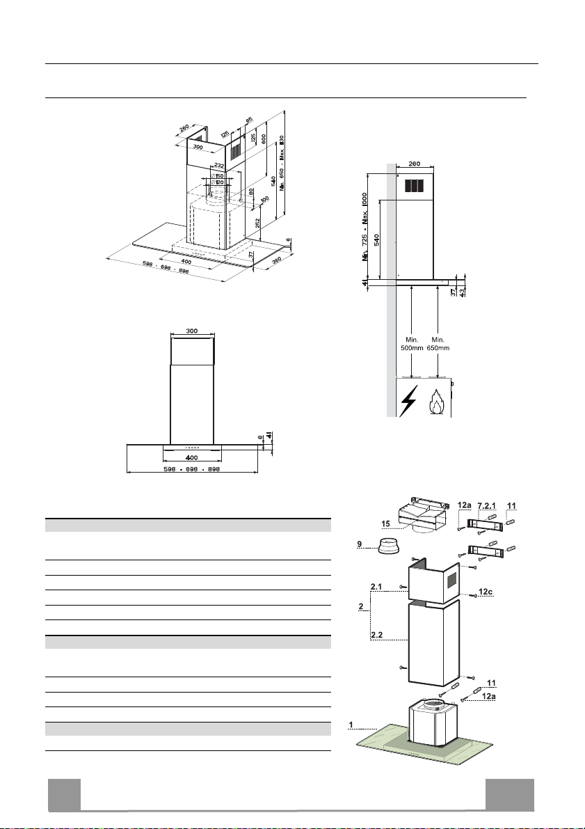
CHARACTERISTICS
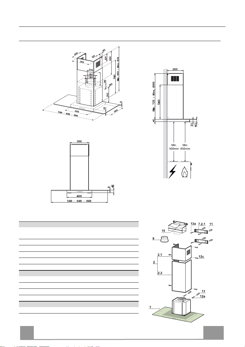
Dimensions
Components
Ref. Q.ty Product Components
1 1 Hood Body, complete with: Controls, Light, Blower,
Filters
2 1 Telescopic Chimney comprising:
2.1 1 Upper Section
2.2 1 Lower Section
9 1 Reducer Flange ø 150-120 mm
15 1 Air Outlet Connection
Ref. Q.ty Installation Components
7.2.1 2 Upper Chimney Section Fixing Brackets
11 6 Wall Plugs
12a 6 Screws 4,2 x 44,4
12c 6 Screws 2,9 x 9,5
Q.ty Documentation
1 Instruction Manual
EN
6
6
Page 7
INSTALLATION
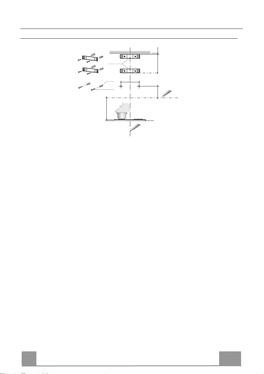
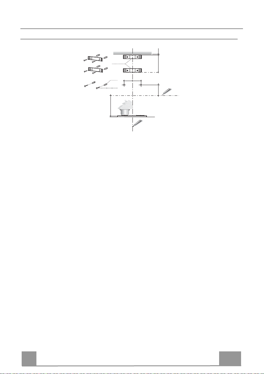
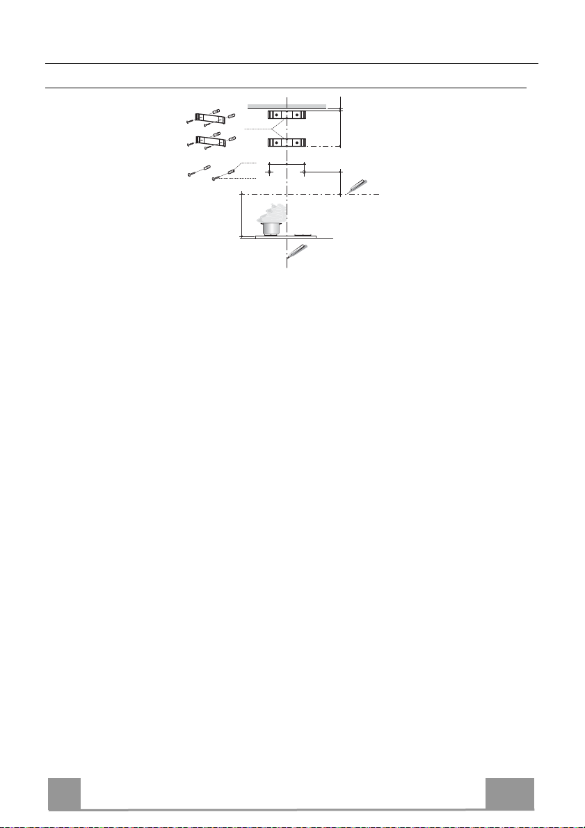
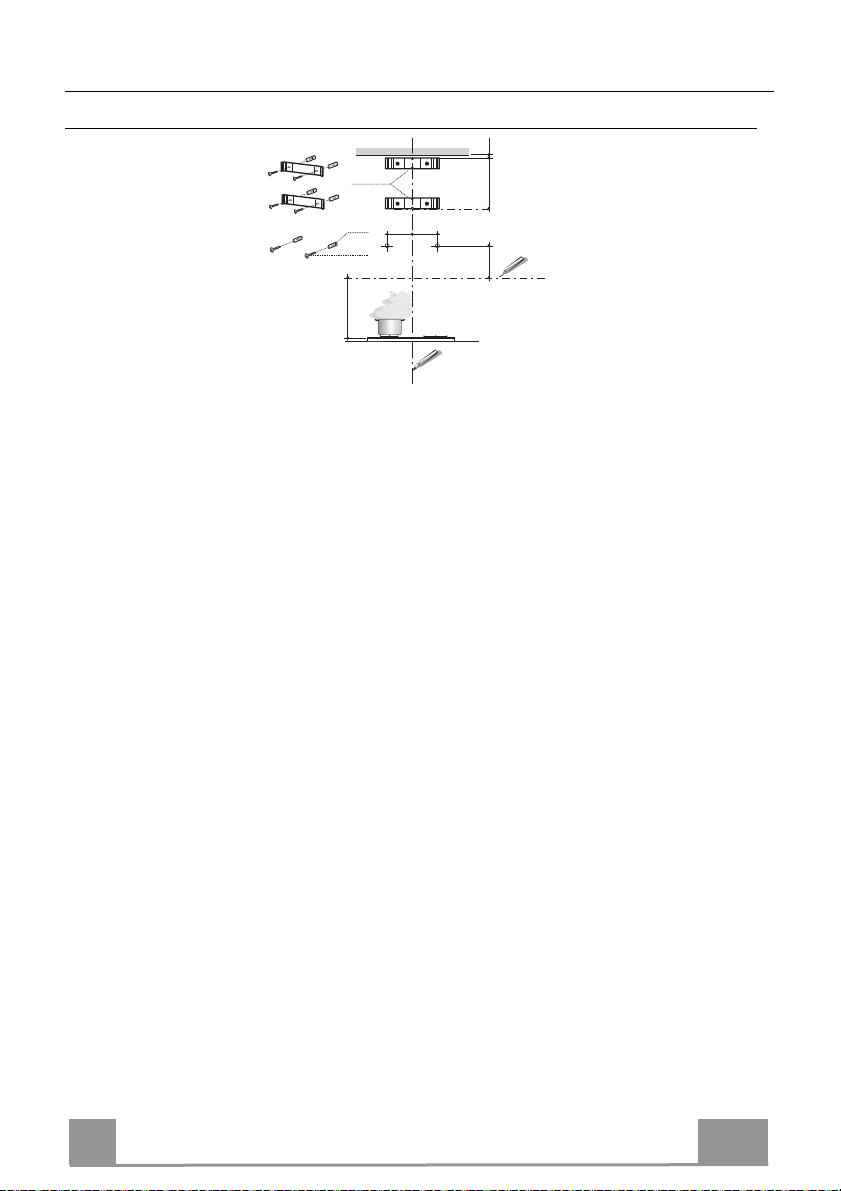
Wall drilling and bracket fixing
1÷2
all marking:
W
7.2.1
11
12a
650 min.
116
116
X
306
• Draw a vertical line on the supporting wall up to the ceiling, or as high as practical, at the
centre of the area in which the hood will be installed.
• Draw a horizontal line at 650 mm above the hob. Place bracket 7.2.1 on the wall as shown
about 1-2 mm from the ceiling or upper limit aligning the centre (notch) with the vertical
reference line.
• Mark the wall at the centres of the holes in the bracket.
• Place bracket 7.2.1 on the wall as shown at X mm below the first bracket (X = height of the
upper chimney section supplied), aligning the centre (notch) with the vertical line.
• Mark the wall at the centres of the holes in the bracket.
• Mark a reference point as indicated at 116 mm from the vertical reference line and 306 mm
above the horizontal reference line.
• Repeat this operation on the other side.
• Drill ø 8 mm holes at all the centre points marked.
• Insert the wall plugs 11 in the holes.
• Fix the brackets using the 12a (4,2 x 44,4) screws supplied.
• Insert the two screws 12a (4,2 x 44,4) supplied in the hood body fixing holes, leaving a gap
of 5-6 mm between the wall and the head of the screw.
EN
7
7
Page 8
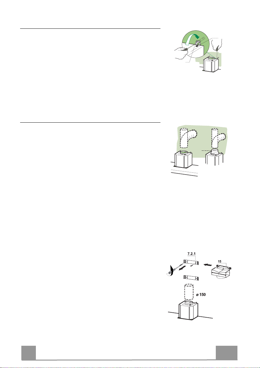
Mounting the hood body
• Before attaching the hood body, tighten the two screws Vr
located on the hood body mounting points.
• Hook the hood body onto the screws 12a.
• Fully tighten the support screws 12a.
• Adjust the screws Vr to level the hood body.
Connections
DUCTED VERSION AIR EXHAUST SYSTEM
When installing the ducted version, connect the hood to the
chimney using either a flexible or rigid pipe ø 150 or 120
mm, the choice of which is left to the installer.
• To install a ø 120 mm air exhaust connection, insert the
reducer flange 9 on the hood body outlet.
• Fix the pipe in position using sufficient pipe clamps (not
supplied).
• Remove any activated charcoal filters.
Vr
12a
ø 120ø 150
9
AIR OUTLET – RECIRCULATION VERSION
• Unfasten the 2 screws fixing the upper bracket 7.2.1.
• Fasten the air outlet connector 15 in its place, using the 2
screws removed as above.
• Join the Connector 15 to the Hood canopy outlet using a
rigid or flexible pipe ø150 mm, selection of which is at the
discretion of the installation technician.
• Make sure that the Activated charcoal odour filter has been
fitted.
EN
8
8
Page 9
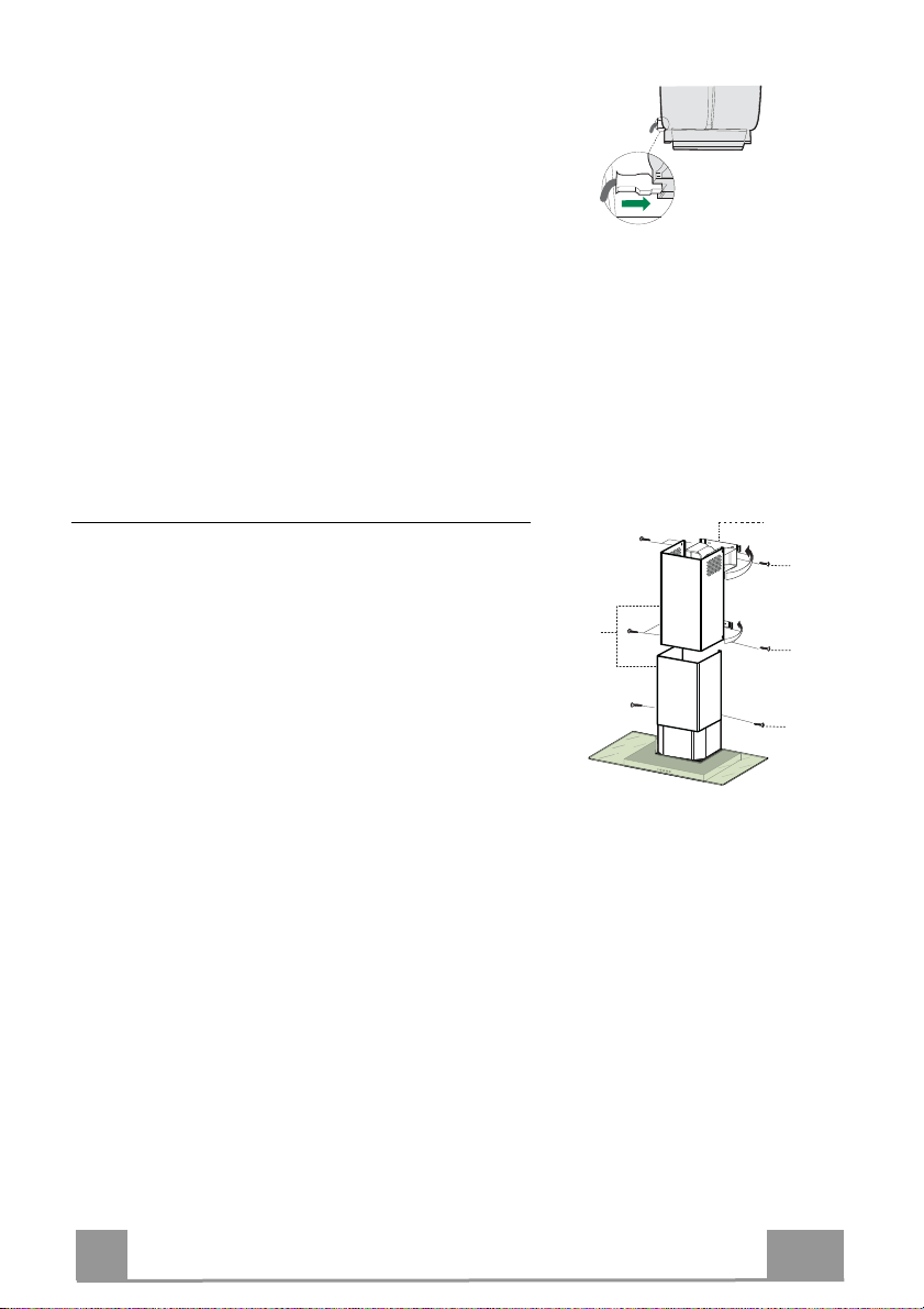
ELECTRICAL CONNECTION
• Connect the hood to the mains through a two-pole
switch having a contact gap of at least 3 mm.
• Remove the grease filters (see paragraph Maintenance) being sure that the connector of the feeding cable is correctly inserted in the socket placed on the
side of the fan.
Flue assembly
Upper exhaust flue
• Slightly widen the two sides of the upper flue and
hook them behind the brackets 7.2.1, making sure that
they are well seated.
• Secure the sides to the brackets by using the 4 screws
12c (2,9 x 9,5) supplied.
• Make sure that the outlet of the extensions pieces is
aligned with the chimney outlets.
Lower exhaust flue
• Slightly widen the two sides of the flue and hook them
between the upper flue and the wall, making sure that
they are well seated.
• Fix the lower part laterally to the hood body by using
the 2 screws 12c (2,9 x 9,5) supplied.
7.2.1
12c
2.1
2
2.2
12c
12c
EN
9
9
Page 10
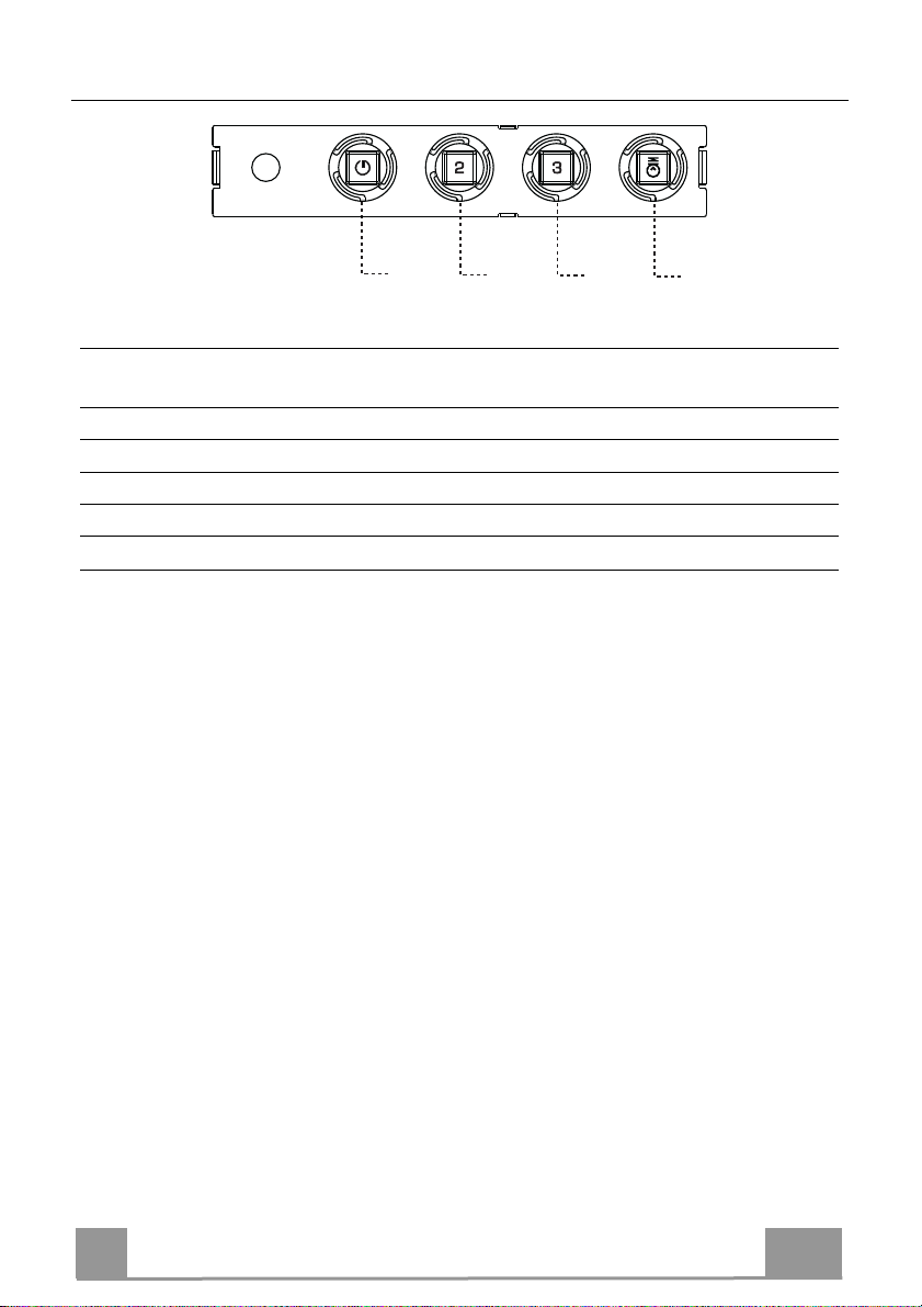
USE
T1
Control panel
BUTTON LED
T1 Speed On Turns the Motor on at Speed one.
T2 Speed On Turns the Motor on at Speed two.
T3 Speed Fixed When pressed briefly, turns the Motor on at Speed three.
L Light Turns the Lighting System on and off.
Warning: Button T1 turns the motor off, after first passing to speed one.
FUNCTIONS
Turns the Motor off.
T2
T3
L
EN
10
1
Page 11
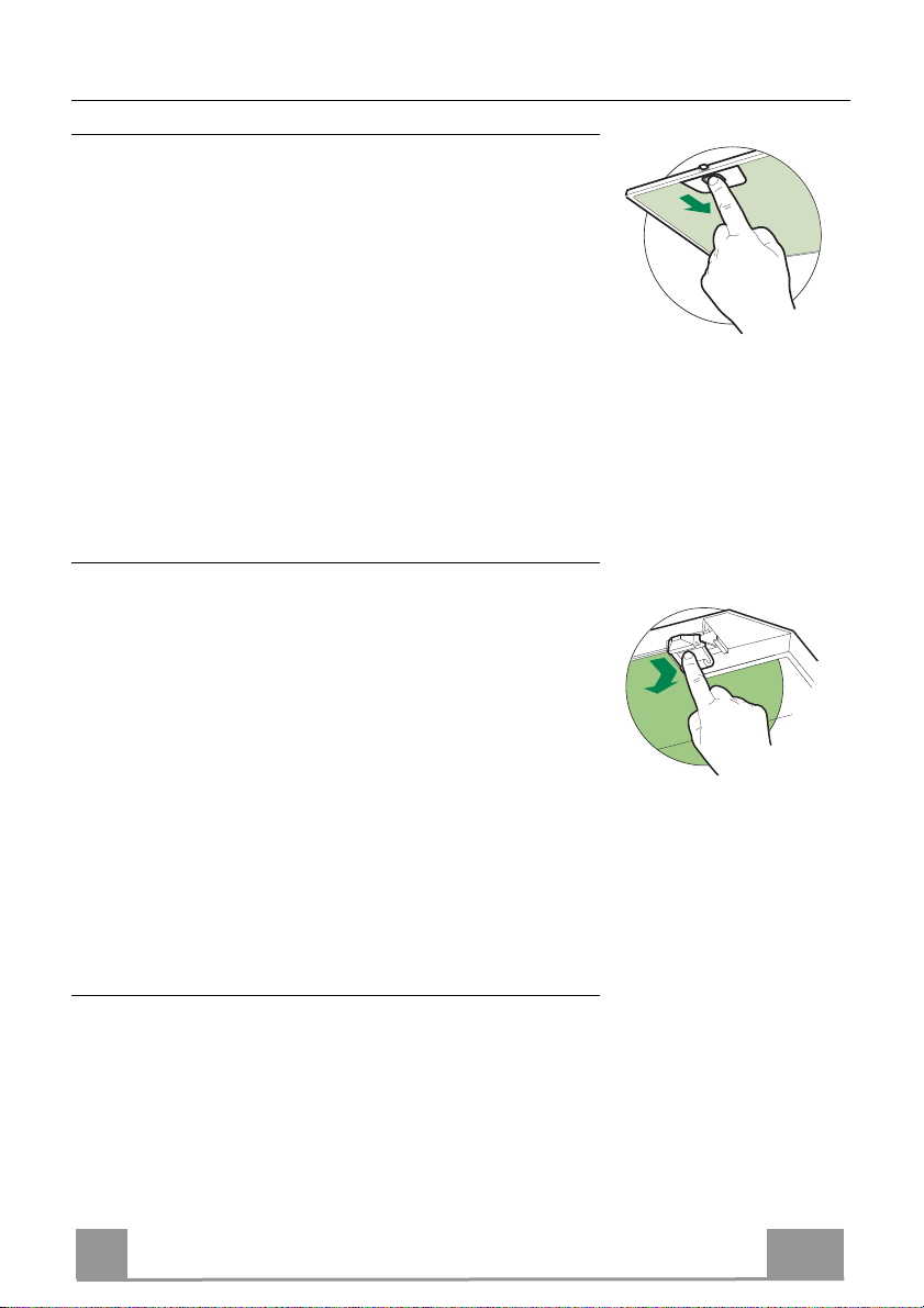
MAINTENANCE
Grease filters
CLEANING METAL SELF- SUPPORTING GREASE FILTERS
• The filters must be cleaned every 2 months of operation, or
more frequently for particularly heavy usage, and can be
washed in a dishwasher.
• Remove the filters one at a time by pushing them towards the
back of the group and pulling down at the same time.
• Wash the filters, taking care not to bend them. Allow them to
dry before refitting.
• When refitting the filters, make sure that the handle is visible
on the outside.
Activated charcoal filter (Recirculation version)
REPLACING THE ACTIVATED CHARCOAL FILTER
• The filter is not washable and cannot be regenerated, and must
be replaced approximately every 4 months of operation, or
more frequently for particularly heavy usage.
• Remove the metal grease filters.
• Remove the saturated activated carbon filter by releasing the
fixing hooks.
• Fit the new filter by hooking it into its seating.
• Refit the metal grease filters.
Lighting unit
• For replacement contact technical support ("To purchase
contact technical support").
EN
11
1
Page 12
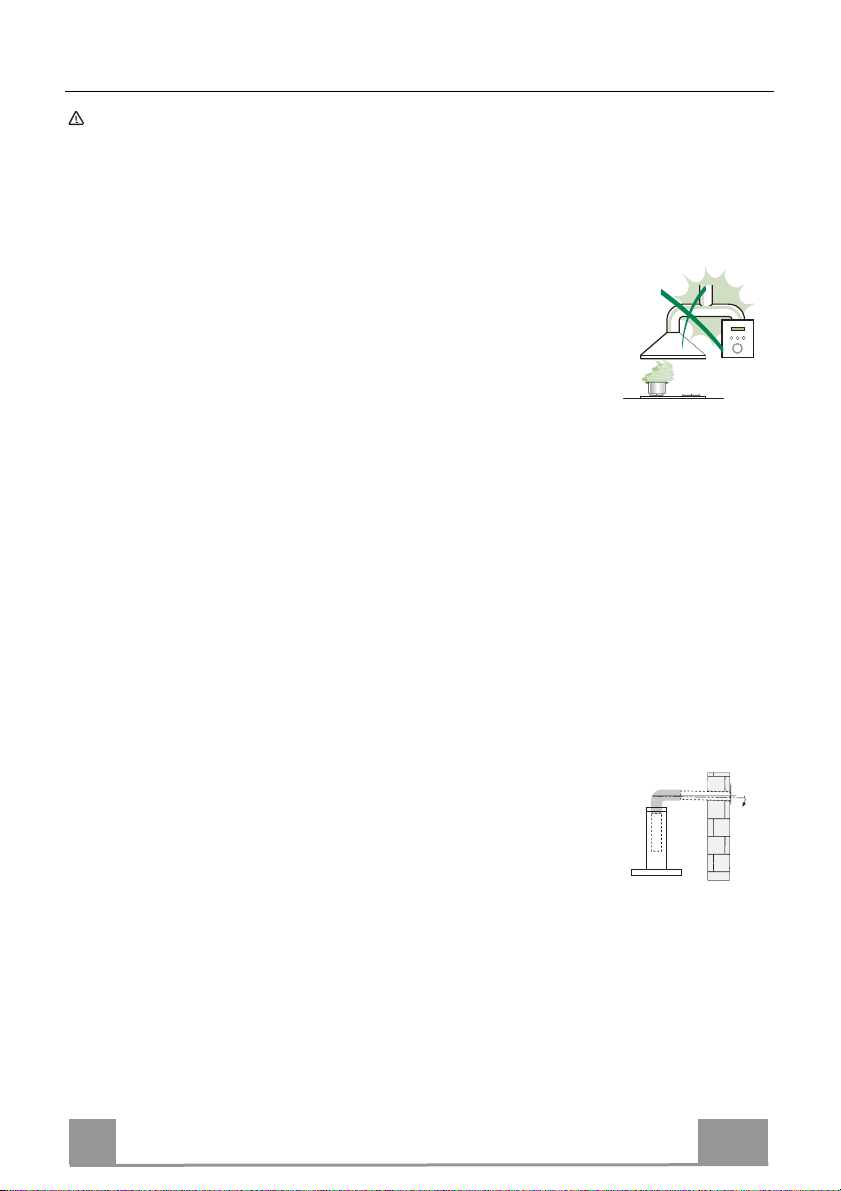
CONSIGLI E SUGGERIMENTI
Le Istruzioni per l’uso si riferiscono ai diversi modelli di questo
apparecchio. Pertanto, si potrebbero trovare descrizioni di singole
caratteristiche che non appartengono al proprio apparecchio specifico.
INSTALLAZIONE
• Il fabbricante non potrà ritenersi responsabile per eventuali
danni risultanti da un’installazione o utilizzazione
impropria.
• La distanza minima di sicurezza tra il piano cottura e la
cappa aspirante è di 650 mm (alcuni modelli possono
essere installati a un’altezza inferiore; vedere il paragrafo
relativo alle dimensioni di lavoro e all'installazione).
• Controllare che la tensione di rete corrisponda a quella indicata sulla targa
dati applicata all’interno della cappa.
• Per gli apparecchi di Classe I, controllare che la rete di alimentazione
domestica disponga di un adeguato collegamento a massa.
Collegare l'aspiratore al condotto dei fumi mediante un tubo con diametro
minimo di 120 mm. Il percorso dei fumi deve essere il più corto possibile.
• Non collegare la cappa aspirante ai condotti fumari che trasportano fumi di
combustione (per es. caldaie, camini ecc.).
• Se l’aspiratore è utilizzato in combinazione con apparecchi non elettrici (per
es. apparecchi a gas), deve essere garantito un sufficiente grado di
aerazione nel locale per impedire il ritorno di flusso dei gas di scarico. La
cucina deve avere un'apertura comunicante direttamente
con l'esterno per garantire l'afflusso di aria pulita. Quando la
cappa per cucina è utilizzata in combinazione con
apparecchi non alimentati dalla corrente elettrica, la
pressione negativa nel locale non deve superare 0,04 mbar
per evitare che i fumi vengano riaspirati nel locale dalla cappa.
• L'aria non deve essere scaricata attraverso un tubo flessibile utilizzato per
l'aspirazione dei fumi da apparecchi alimentati a gas o altri combustibili (non
utilizzare con apparecchi che scaricano unicamente l'aria nel locale).
• In caso di danneggiamento del cavo di alimentazione, occorre farlo sostituire
dal produttore o dal reparto di assistenza tecnica per evitare qualsiasi
rischio.
2°
IT
12
1
Page 13
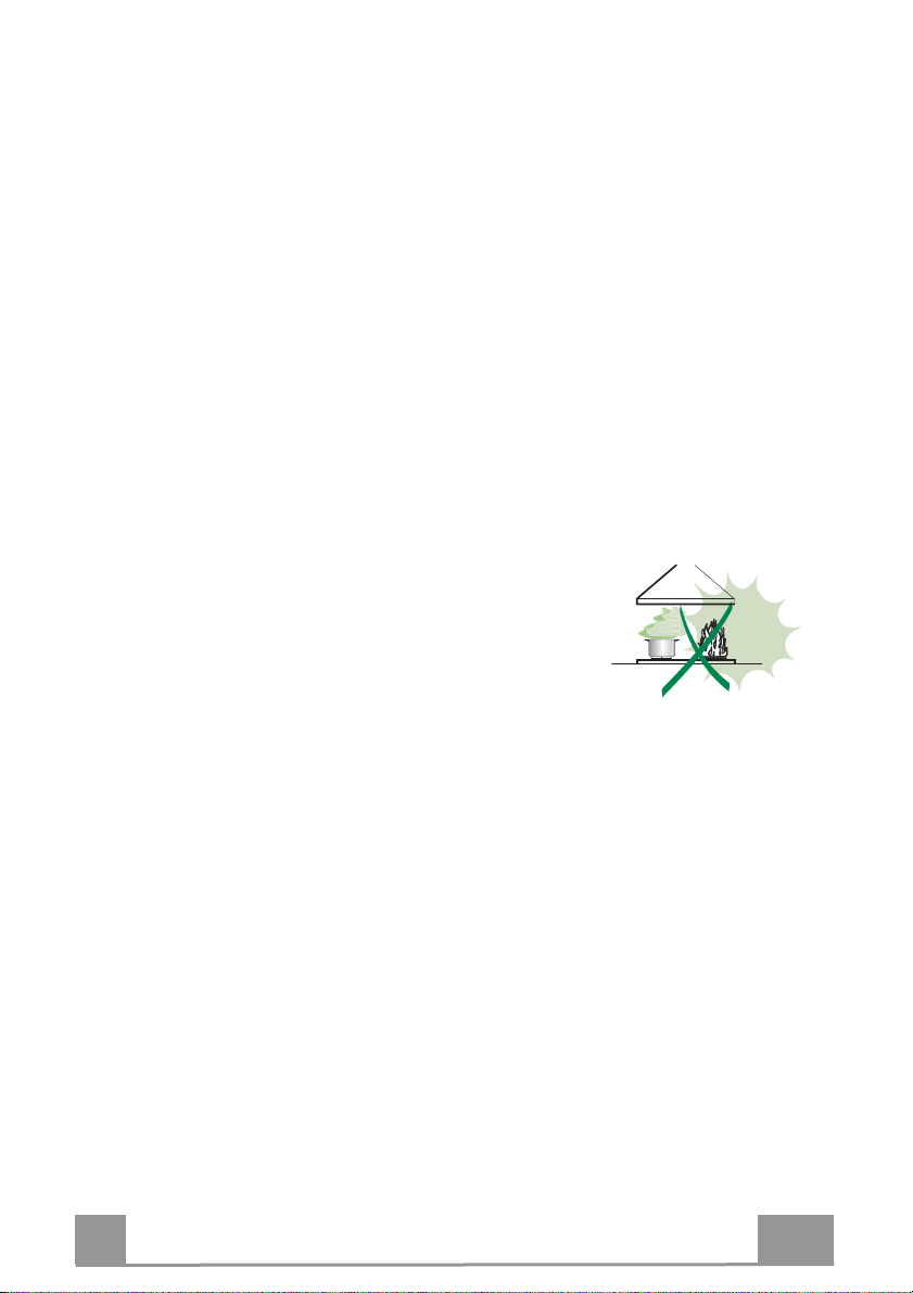
• Se le istruzioni di installazione del piano cottura a gas specificano una
distanza maggiore di quella sopra indicata, è necessario tenerne conto.
Devono essere rispettate tutte le normative riguardanti lo scarico dell'aria.
• Usare solo viti e minuteria di tipo idoneo per la cappa.
Avvertenza: la mancata installazione delle viti o dei dispositivi di fissaggio in
conformità alle presenti istruzioni può comportare rischi di scosse elettriche.
• Collegare la cappa all'alimentazione di rete mediante un interruttore bipolare
con distanza tra i contatti di almeno 3 mm.
USO
• La cappa aspirante è progettata esclusivamente per l’uso domestico allo
scopo di eliminare gli odori dalla cucina.
• Non usare mai la cappa per scopi diversi da quelli per cui è stata progettata.
• Non lasciare mai fiamme alte sotto la cappa quando è in funzione.
• Regolare l'intensità della fiamma in modo da dirigerla esclusivamente verso
il fondo del recipiente di cottura, assicurandosi che non ne avvolga i lati.
• Le friggitrici devono essere costantemente
controllate durante l’uso: l’olio surriscaldato
potrebbe incendiarsi.
• Non cuocere al flambé sotto la cappa: si potrebbe
sviluppare un incendio.
• Questo apparecchio può essere utilizzato da
bambini di età non inferiore a 8 anni e da persone con ridotte capacità psicofisico-sensoriali o con esperienza e conoscenze insufficienti, purché
attentamente sorvegliati e istruiti su come utilizzare in modo sicuro
l'apparecchio e sui pericoli che ciò comporta. Assicurarsi che i bambini non
giochino con l'apparecchio. Pulizia e manutenzione da parte dell'utente non
devono essere effettuate da bambini, a meno che non siano sorvegliati.
• Questo apparecchio non deve essere utilizzato da persone (bambini
compresi) con ridotte capacità psico-fisico-sensoriali o con esperienza e
conoscenze insufficienti, a meno che non siano attentamente sorvegliate e
istruite da una persona responsabile della loro incolumità.
IT
13
1
Page 14

• “ATTENZIONE: le parti accessibili possono diventare molto calde durante
l’uso degli apparecchi di cottura”.
MANUTENZIONE
• Spegnere o scollegare l’apparecchio dalla rete di alimentazione prima di
qualunque operazione di pulizia o manutenzione.
• Pulire e/o sostituire i filtri dopo il periodo di tempo specificato (pericolo di
incendio).
• I filtri antigrasso devono essere puliti ogni 2 mesi di funzionamento o più
frequentemente in caso di utilizzo molto intenso e possono essere lavati in
lavastoviglie.
• Il filtro al carbone attivo non è lavabile né è rigenerabile e deve essere
sostituito ogni 4 mesi di funzionamento circa o più frequentemente in caso di
utilizzo molto intenso.
• "Vi è il rischio di incendio se la pulizia non viene effettuata secondo le
istruzioni".
• Pulire la cappa utilizzando un panno umido e un detergente liquido neutro.
Il simbolo sul prodotto o sulla sua confezione indica che il prodotto non
può essere smaltito come un normale rifiuto domestico. Il prodotto da smaltire
deve essere conferito presso un apposito centro di raccolta per il riciclaggio
dei componenti elettrici ed elettronici. Assicurandosi che questo prodotto sia
smaltito correttamente, si contribuirà a prevenire potenziali conseguenze
negative per l’ambiente e per la salute che potrebbero altrimenti derivare dal
suo smaltimento inadeguato. Per informazioni più dettagliate sul riciclaggio di
questo prodotto, contattare il Comune, il servizio locale di smaltimento rifiuti
oppure il negozio dove è stato acquistato il prodotto.
IT
14
1
Page 15
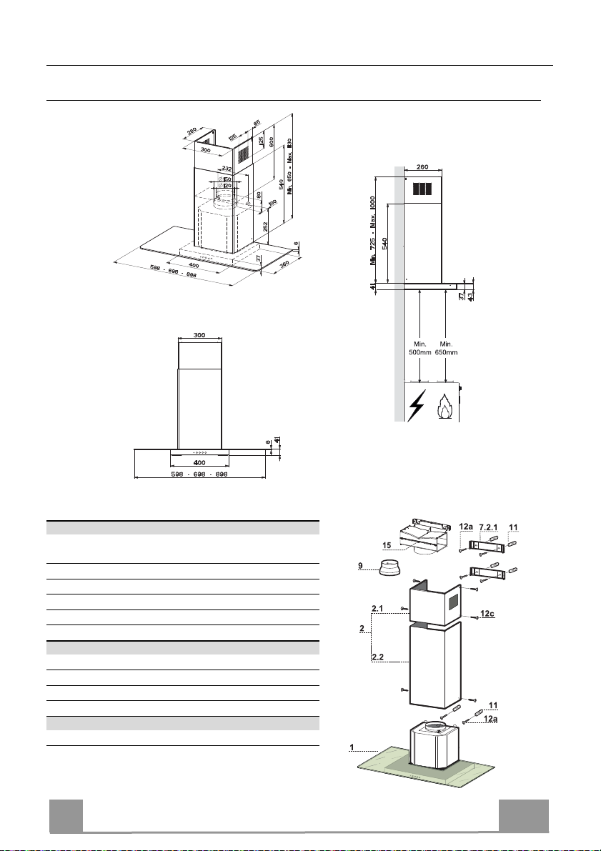
CARATTERISTICHE
Ingombro
Componenti
Rif. Q.tà Componenti di Prodotto
1 1 Corpo Cappa completo di: Comandi, Luce, Grup-
po Ventilatore, Filtri
2 1 Camino Telescopico formato da:
2.1 1 Camino Superiore
2.2 1 Camino Inferiore
9 1 Flangia di Riduzione ø 150-120 mm
15 1 Raccordo Uscita Aria
Rif. Q.tà Componenti di Installazione
7.2.1 2 Staffe Fissaggio Camino Superiore
11 6 Tasselli
12a 6 Viti 4,2 x 44,4
12c 6 Viti 2,9 x 9,5
Q.tà Documentazione
1 Libretto Istruzioni
IT
15
1
Page 16
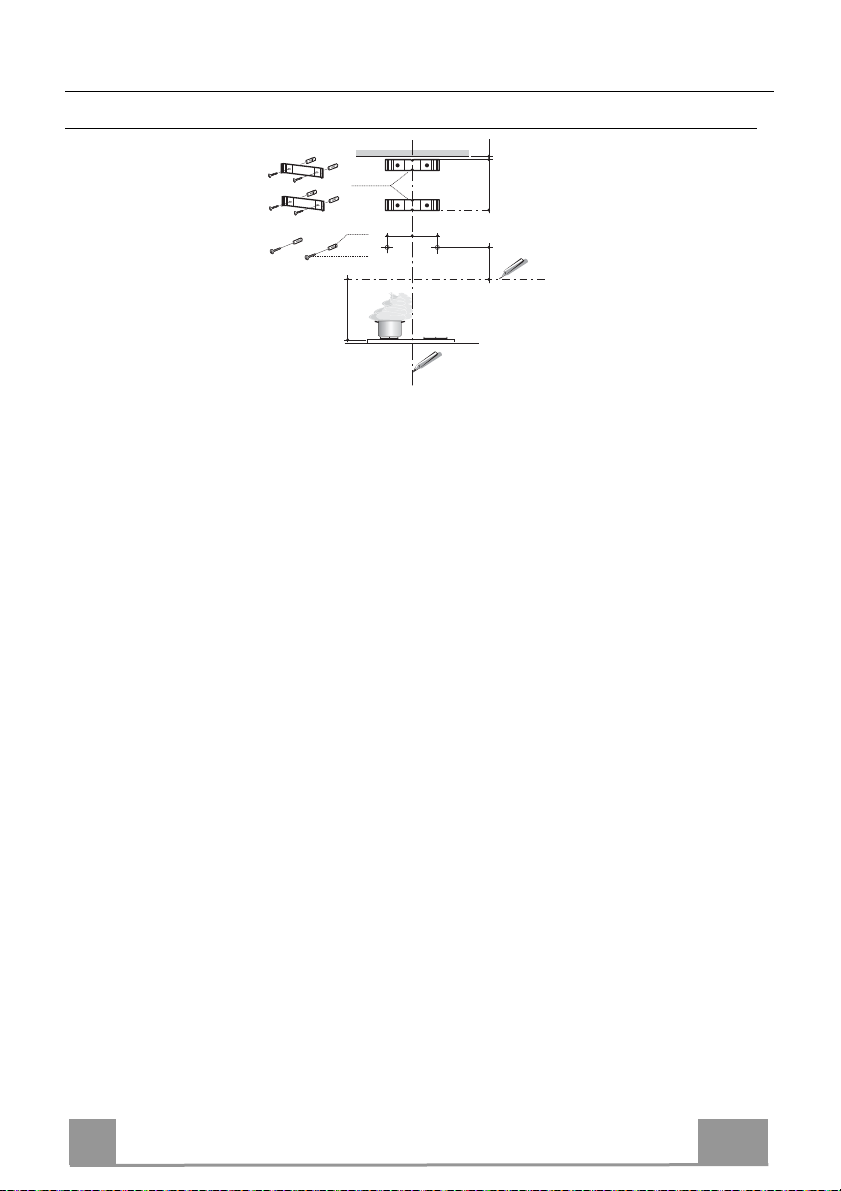
INSTALLAZIONE
Foratura Parete e Fissaggio Staffe
1÷2
7.2.1
11
116
116
12a
650 min.
ciare sulla Parete:
Trac
• una linea Verticale fino al soffitto o al limite superiore, al centro della zona prevista per il
montaggio della Cappa;
• una linea Orizzontale a: 650 mm min. sopra il Piano di Cottura.
• Appoggiare come indicato la Staffa 7.2.1 a 1-2 mm dal soffitto o dal limite superiore, allineando il suo centro (intagli) sulla linea Verticale di riferimento.
• Segnare i centri dei Fori della Staffa.
• Appoggiare come indicato la Staffa 7.2.1 a X mm sotto la prima staffa (X = altezza Camino
Superiore in dotazione), allineando il suo centro (intagli) sulla linea Verticale di riferimento.
• Segnare i centri dei Fori della Staffa.
• Segnare come indicato, un punto di riferimento a 116 mm dalla linea Verticale di riferimento, e 306 mm sopra la linea Orizzontale di riferimento.
• Ripetere questa operazione dalla parte opposta.
• Forare ø 8 mm i punti segnati.
• Inserire i tasselli 11 nei fori.
• Fissare le Staffe, utilizzando le Viti 12a (4,2 x 44,4 ) in dotazione.
• Avvitare 2 Viti 12a (4,2 x 44,4) in dotazione nei fori per il fissaggio del corpo Cappa, lasciando uno spazio di 5-6 mm fra la parete e la testa della vite.
X
306
IT
16
1
Page 17
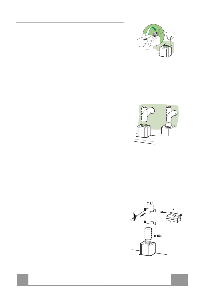
Montaggio Corpo Cappa
• Prima di agganciare il Corpo Cappa, serrare le 2 Viti Vr
situate sui punti di aggancio del Corpo Cappa.
• Agganciare il Corpo Cappa alle Viti 12a.
• Serrare definitivamente le Viti 12a di supporto.
• Agire sulle Viti Vr per livellare il Corpo Cappa.
Connessioni
USCITA ARIA VERSIONE ASPIRANTE
Per installazione in Versione Aspirante collegare la Cappa
alla tubazione di uscita per mezzo di un tubo rigido o flessibile di ø150 o 120 mm, la cui scelta è lasciata all'installatore.
• Per collegamento con tubo ø120 mm, inserire la Flangia
di riduzione 9 sull’Uscita del Corpo Cappa.
• Fissare il tubo con adeguate fascette stringitubo. Il materiale occorrente non è in dotazione.
• Togliere eventuali Filtri Antiodore al Carbone attivo.
Vr
12a
ø 120ø 150
9
USCITA ARIA VERSIONE FILTRANTE
• Svitare le 2 Viti che fissano la Staffa Superiore 7.2.1.
• Avvitare al suo posto il Raccordo Uscita Aria 15 con le 2
viti tolte in precedenza.
• Collegare il Raccordo 15 all’Uscita del Corpo Cappa per
mezzo di un tubo rigido o flessibile di ø150 mm, la cui
scelta è lasciata all'installatore.
• Assicurarsi della presenza del Filtro Antiodore al Carbone attivo.
IT
17
1
Page 18
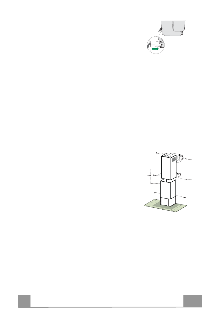
CONNESSIONE ELETTRICA
• Collegare la Cappa all’Alimentazione di Rete interponendo un Interruttore bipolare con apertura dei contatti di
almeno 3 mm.
• Rimuovere i Filtri antigrasso (vedi par. “Manutenzione”)
e assicurarsi che il connettore del Cavo di alimentazione
sia correttamente inserito nella presa dell’Aspiratore
Montaggio Camino
Camino superiore
• Allargare leggermente le due falde laterali, agganciarle
dietro le Staffe 7.2.1 e richiuderle fino a battuta.
• Fissare lateralmente alle Staffe con 4 Viti 12c (2,9 x 9,5)
in dotazione.
• Assicurarsi che l’uscita delle Prolunghe Raccordo risulti
in corrispondenza delle bocchette del Camino.
Camino inferiore
• Allargare leggermente le due falde laterali del Camino,
agganciarle tra il Camino superiore e la parete e richiuderle fino a battuta.
• Fissare lateralmente la parte inferiore al Corpo Cappa,
con 2 Viti 12c (2,9 x 9,5) in dotazione.
7.2.1
12c
2.1
2
2.2
12c
12c
IT
18
1
Page 19
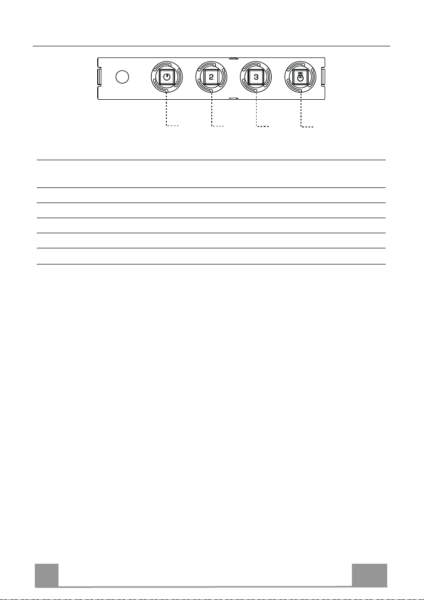
USO
T1
Quadro comandi
TASTO
T1 Velocità Acceso Accende il Motore alla Prima velocità.
T2 Velocità Acceso Accende il Motore alla Seconda velocità.
T3 Velocità Fisso Premuto brevemente Accende il Motore alla Terza velocità.
L Luce Accende e spegne l’Impianto di Illuminazione.
Attenzione: Il tasto T1 spegne il motore passando sempre per la prima velocità.
LED FUNZIONI
Spegne il Motore.
T2
T3
L
IT
19
1
Page 20
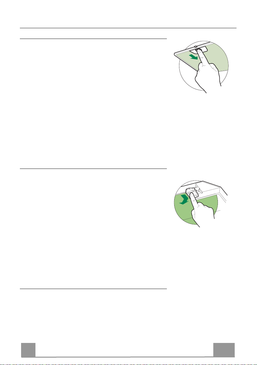
MANUTENZIONE
Filtri antigrasso
PULIZIA FILTRI ANTIGRASSO METALLICI AUTOPORTANTI
• Sono lavabili anche in lavastoviglie, e necessitano di essere
lavati ogni 2 mesi circa di utilizzo o più frequentemente, per un
uso particolarmente intenso.
• Togliere i Filtri uno alla volta, spingendoli verso la parte posteriore del gruppo e tirando contemporaneamente verso il basso.
• Lavare i Filtri evitando di piegarli, e lasciarli asciugare prima
di rimontarli.
• Rimontarli facendo attenzione a mantenere la maniglia verso la
parte visibile esterna.
Filtro antiodore (Versione Filtrante)
SOSTITUZIONE FILTRO ANTIODORE AL CARBONE ATTIVO
• Non è lavabile e non è rigenerabile, va sostituito almeno ogni 4
mesi o più frequentemente, per un uso particolarmente intenso.
• Togliere i Filtri antigrasso metallici.
• Rimuovere il Filtro antiodore al Carbone attivo saturo, agendo
sugli appositi agganci.
• Montare il nuovo Filtro agganciandolo nella sua sede.
• Rimontare i Filtri antigrasso metallici.
Illuminazione
• Per la sostituzione contattare l’Assistenza Tecnica ("Per
l'acquisto rivolgersi all'assistenza tecnica").
IT
20
2
Page 21
CONSEILS ET SUGGESTIONS
Les instructions pour l’utilisation se réfèrent aux différents modèles de cet
appareil. Par conséquent, certaines descriptions de caractéristiques particulières
pourraient ne pas appartenir spécifiquement à cet appareil.
INSTALLATION
• En aucun cas le fabricant ne peut être tenu pour responsable d’éventuels
dommages dus à une installation ou à une utilisation impropre.
• La distance de sécurité minimum entre le plan de cuisson et la
hotte aspirante est de 650 mm (certains modèles peuvent être
installés à une hauteur inférieure ; voir le paragraphe
concernant les dimensions de travail et l’installation).
• Assurez-vous que la tension de votre secteur correspond à
celle indiquée sur la plaque des données appliquée à l’intérieur de la hotte.
• Pour les appareils de Classe I, s’assurer que l’installation électrique de votre
intérieur dispose d’une mise à la terre adéquate.
Relier l’aspirateur au conduit de cheminée avec un tube d’un diamètre minimum
de 120 mm. Le parcours des fumées doit être le plus court possible.
• Ne pas relier la hotte aspirante aux conduits de cheminée qui
acheminent les fumées de combustion (par exemple de
chaudières, de cheminées, etc.).
• Si vous utilisez l’aspirateur en combinaison avec des
appareils non électriques (par ex. appareils à gaz), vous
devez garantir un degré d’aération suffisant dans la pièce,
afin d’empêcher le retour du flux des gaz de sortie. La cuisine doit présenter une
ouverture communiquant directement vers l’extérieur pour garantir l’amenée d’air
propre. Si vous utilisez la hotte de cuisine en combinaison avec des appareils non
alimentés à l’électricité, la pression négative dans la pièce ne doit pas dépasser
0,04 mbar afin d’éviter que la hotte ne réaspire les fumées dans la pièce.
• Ne pas évacuer l’air à travers un tube flexible utilisé pour l’aspiration des fumées
des appareils alimentés au gaz ou avec d’autres combustibles (ne pas utiliser
avec des appareils ayant une seule sortie d’air dans la pièce).
• Si le cordon d’alimentation est endommagé, veuillez le faire remplacer par le
fabricant ou par un service après-vente agréé pour éviter tout risque d’accident.
2°
FR
21
2
Page 22
• Si les instructions d’installation du plan de cuisson à gaz spécifient une
distance supérieure à celle indiquée ci-dessus, veuillez impérativement en
tenir compte. Toutes les normes concernant l’évacuation de l’air doivent être
respectées.
• Utiliser exclusivement des vis et des petites pièces du type adapté pour la
hotte.
Attention : toute installation des vis et des dispositifs de fixation non
conforme aux présentes instructions peut entraîner des risques de
décharges électriques.
• Brancher la hotte à l’alimentation de secteur avec un interrupteur bipolaire
ayant une ouverture des contacts d’au moins 3 mm.
UTILISATION
• Cette hotte aspirante a été conçue exclusivement pour un usage
domestique, dans le but d’éliminer les odeurs de cuisine.
• Ne jamais utiliser la hotte pour des objectifs différents de ceux pour lesquels
elle a été conçue.
• Ne jamais laisser un feu vif allumé sous la hotte lorsque celle-ci est en
fonction.
• Régler l’intensité du feu de manière à l’orienter exclusivement vers le fond
de la casserole, en vous assurant qu’il ne déborde pas sur les côtés.
• Contrôler constamment les friteuses durant leur
utilisation : l’huile surchauffée risque de s’incendier.
• Ne pas flamber des mets sous la hotte : sous risque
de provoquer un incendie.
• Cet appareil n’est pas destiné à être utilisé par des
enfants d’un âge inférieur à 8 ans, ni par des personnes dont les capacités
physiques, sensorielles ou mentales sont diminuées ou qui ont une
expérience et des connaissances insuffisantes, à moins que ces enfants ou
ces personnes ne soient attentivement surveillés et instruits sur la manière
d’utiliser cet appareil en sécurité et sur les dangers que cela comporte.
Assurez-vous que les enfants ne jouent pas avec cet appareil. Le nettoyage
et l’entretien de la part de l’utilisateur ne doivent pas être effectués par des
enfants, à moins que ce ne soit sous la surveillance d’une personne
responsable.
FR
22
2
Page 23

• ATTENTION : les parties accessibles peuvent devenir très chaudes durant
l’utilisation des appareils de cuisson.
ENTRETIEN
• Avant d’effectuer toute opération de nettoyage et d’entretien, éteindre ou
débrancher l’appareil du secteur.
• Nettoyer et/ou remplacer les filtres après le délai indiqué (danger
d’incendie).
• Nettoyer les filtres à graisse tous les 2 mois de fonctionnement ou plus
souvent en cas d’utilisation particulièrement intense. Ces filtres peuvent être
lavés au lave-vaisselle.
• Le filtre à charbon actif ne peut être ni lavé ni régénéré et il doit être
remplacé environ tous les 4 mois de fonctionnement ou plus souvent en cas
d’utilisation particulièrement intense.
• Effectuer le nettoyage selon les instructions, sous risque d'incendie.
• Nettoyer la hotte avec un chiffon humide et un détergent liquide neutre.
Le symbole marqué sur le produit ou sur son emballage indique que ce
produit ne peut pas être éliminé comme déchet ménager normal. Lorsque ce
produit doit être éliminé, veuillez le remettre à un centre de collecte prévu pour
le recyclage du matériel électrique et électronique. En vous assurant que cet
appareil est éliminé correctement, vous participez à prévenir des
conséquences potentiellement négatives pour l'environnement et pour la
santé, qui risqueraient de se présenter en cas d’élimination inappropriée. Pour
toute information supplémentaire sur le recyclage de ce produit, contactez
votre municipalité, votre déchetterie locale ou le magasin où vous avez acheté
ce produit.
FR
23
2
Page 24
CARACTERISTIQUES
Encombrement
Composants
Réf. Q.té Composants de Produit
1 1 Corps Hotte équipé de:Commandes, Lumière, Groupe
Ventilateur,Filtres
2 1 Cheminée Télescopique formée de :
2.1 1 Cheminée Supérieure
2.2 1 Cheminée Inférieure
9 1 Flasque de Réduction ø 150-120 mm
15 1 Raccord Sortie Air
Réf. Q.té Composants pour l ’installation
7.2.1 2 Brides Fixation Cheminée Supérieure
11 6 Chevilles
12a 6 Vis 4,2 x 44,4
12c 6 Vis 2,9 x 9,5
Q.té Documentation
1 Manuel d’instructions
FR
24
2
Page 25
INSTALLATION
Perçage Paroi et Fixation Brides
1÷2
7.2.1
X
er sur la paroi:
Trac
11
12a
650 min.
116
116
306
• une ligne verticale allant jusqu’au plafond ou à la limite supérieure, au centre de la zone
prévue pour le montage de la hotte;
• une ligne horizontale à 650 mm min. au-dessus du plan de cuisson.
• Poser comme indiqué une bride 7.2.1 sur la paroi à 1-2 mm du plafond ou de la limite supérieure, en alignant son centre (découpes) sur la ligne verticale de repère.
• Marquer les centres des trous rainurés de la bride.
• Poser comme indiqué la bride 7.2.1 à X mm sous la première bride (X = hauteur cheminée
supérieure fournie), en alignant son centre (découpes) sur la ligne verticale de repère.
• Marquer les centres des trous rainurés de la bride.
• Marquer comme indiqué, un point de référence à 116 mm de la ligne verticale de repère, et
306 mm au-dessus de la ligne horizontale de repère.
• Répéter cette opération sur le côté opposé.
• Percer de ø 8 mm tous les points marqués.
• Insérer les chevilles 11 dans les trous.
• Fixer les brides en utilisant les vis 12a (4,2 x 44,4) fournies.
• Visser les 2 vis 12a (4,2 x 44,4) fournies dans les trous de fixation du corps hotte, en laissant
un espace de 5-6 mm entre le mur et la tête de la vis.
FR
25
2
Page 26
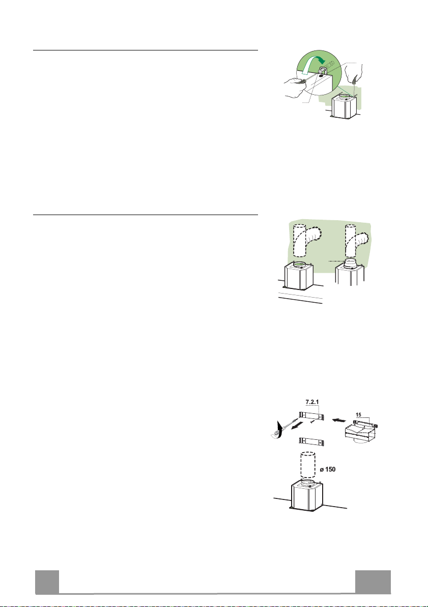
Montage Corps Hotte
• Avant d’accrocher le corps hotte, serrer les deux vis Vr
situées sur les points d’accrochage du corps hotte.
• Accrocher le corps hotte aux vis 12a prévues à cet effet.
• Serrer définitivement les vis 12a de support.
• Agir sur les vis Vr pour niveler le corps hotte.
Branchements
SORTIE AIR VERSION ASPIRANTE
Pour l’installation en version aspirante, relier la hotte au
tube de sortie au moyen d’un tube rigide ou flexible de ø
150 ou 120 mm dont le choix est laissé à l’installateur.
• Pour la liaison avec le tube ø120 mm, insérer la buse de
réduction 9 sur la sortie du corps de la hotte.
• Fixer le tube avec des colliers serre-tube appropriés. Le
matériel nécessaire n’est pas fourni.
• Retirer les filtres anti-odeur à charbon actif éventuels.
Vr
12a
ø 120ø 150
9
SORTIE AIR VERSION FILTRANTE
• Desserrer les 2 vis de fixation du support supérieur 7.2.1.
• Visser à sa place le raccord de sortie de l’air 15 avec les 2
vis précédemment retirées.
• Relier le raccord 15 à la sortie du corps de hotte au
moyen d’un tube rigide ou flexible de ø 150 mm, au
choix de l'installateur.
• S’assurer de la présence du filtre anti-odeur au charbon
actif.
FR
26
2
Page 27
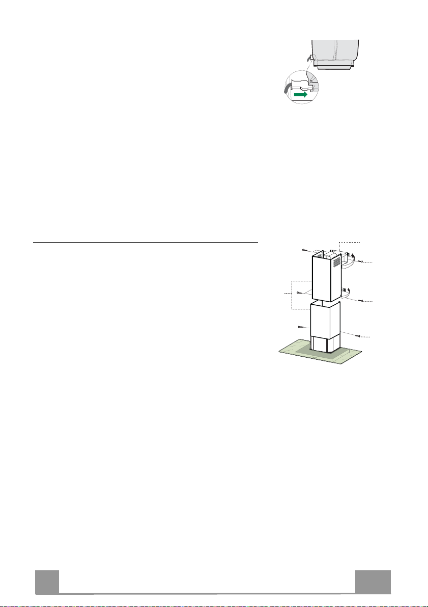
BRANCHEMENT ELECTRIQUE
• Brancher la hotte sur le secteur en interposant un
interrupteur bipolaire avec ouverture des contacts d’au
moins 3 mm.
• Enlever les filtres à graisse (voir § "Entretien") et s'assurer que le connecteur du câble d'alimentation soit bien
branché dans la prise du diffuseur.
Montage Cheminée
Cheminée supérieure
• Elargir légèrement les deux bords latéraux, et les
accrocher derrières les brides 7.2.1 ; refermer jusqu’en
butée.
• Fixer latéralement aux brides à l’aide des 4 vis 12c
fournies.
• S’assurer que la sortie des rallonges raccord se trouve au
niveau des bouches de la cheminée.
Cheminée inférieure
• Elargir légèrement les deux bords latéraux de la cheminée
et les accrocher entre la cheminée supérieure et la paroi;
refermer jusqu’en butée.
• Fixer latéralement la partie inférieure au corps de la hotte,
à l’aide des deux 2 vis 12c fournies.
7.2.1
12c
2.1
2
2.2
12c
12c
FR
27
2
Page 28
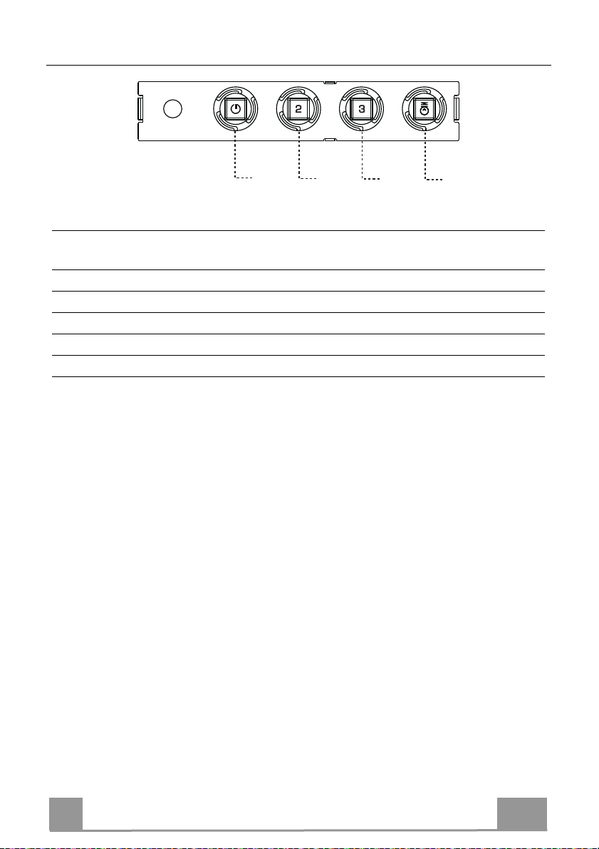
UTILISATION
T1
Tableau des commandes
TOUCHE VOYANT
T1 Vitesse Allumé Démarre le moteur en première vitesse.
T2 Vitesse Allumé Démarre le moteur en deuxième vitesse.
T3 Vitesse Fixe Appuyée brièvement, démarre le moteur en troisième vitesse.
L Lumière Branche et débranche l’éclairage.
Attention : La touche T1 coupe le moteur en passant toujours par la première vitesse.
FONCTIONS
Coupe le moteur.
T2
T3
L
FR
28
2
Page 29
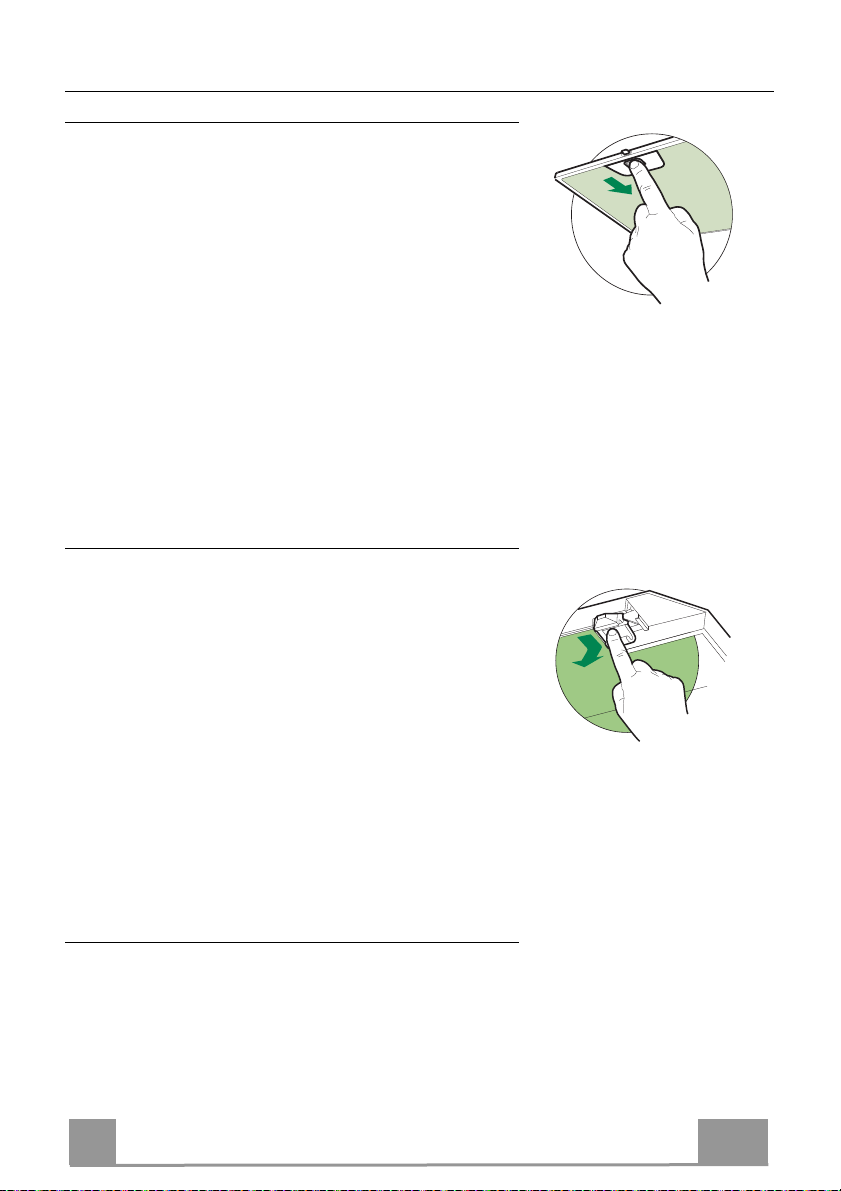
ENTRETIEN
Filtres anti-graisse
NETTOYAGE FILTRES ANTI-GRAISSE METALLIQUES AUTOPORTEURS
• Lavables au lave-vaisselle, ils doivent être lavés environ
tous les 2 mois d’emploi ou plus fréquemment en cas
d’emploi par
• Retirer les filtres l’un aprés l’autre, en les poussant vers la
partie arrière du groupe et en tirant simultanément vers le
bas.
• Laver les filtres en évitant de les plier et les laisser sécher
avant de les remonter.
• Remonter les filtres en veillant à ce que la poignée reste
vers la partie visible externe
• Ni lavable, ni régénérable, le remplacer au moins tous les 4
mois d’emploi ou plus fréquemment en cas d’emploi particulièrement intense.
• Retirer les filtres anti-graisse métalliques.
• Retirer le filtre anti-odeur au charbon actif colmaté, en
agissant sur les crochets prévus à cet effet.
• Monter le nouveau filtre anti-odeur au charbon actif.
• Remonter les filtres anti-graisse métalliques.
ticulièrement intense.
Filtre anti-odeur (Version filtrante)
REMPLACEMENT FILTRE AU CHARBON ACTIF
Éclairage
• Pour le remplacement, contacter le Service après-vente
(« Pour l’achat, s’adresser au service après-vente »).
FR
29
2
Page 30
EMPFEHLUNGEN UND HINWEISE
Diese Gebrauchsanleitungen beziehen sich auf die verschiedenen Modelle
der Abzugshaube. Darum kann es möglich sein, dass die Beschreibung
bestimmter Merkmale für das vorliegende Gerät nicht zutrifft.
INSTALLATION
• Der Hersteller haftet nicht für etwaige Schäden, die durch die fehlerhafte
Installation oder falschen Gebrauch entstehen könnten.
• Der min. Sicherheitsabstand zwischen Kochfeld und
Abzugshaube beträgt 650 mm (einige Modelle können auch
niedriger installiert werden; siehe Absatz Installation).
• Kontrollieren Sie, ob die Netzspannung den Daten des
Typenschilds im Innern der Haube entspricht.
• Für Geräte der Klasse I muss kontrolliert werden, ob das
häusliche Versorgungsnetz korrekt geerdet ist.
Die Absaughaube mit Hilfe eines Rohrs mit einem Mindestdurchmesser von
120 mm mit dem Rauchabzug verbinden. Der Verlauf des Rauchabzugs soll
so kurz wie möglich sein.
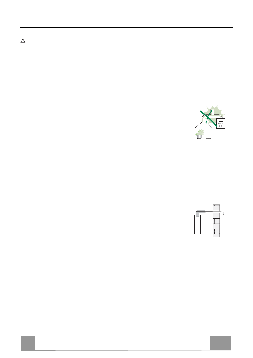
• Die Abzugshaube darf nicht an einen Schacht angeschlossen werden, in den
Rauchgase geleitet werden (z. B. von Heizkessel, Kaminen, usw.).
• Falls in dem Raum neben dem Abzug auch nicht mit Strom
betriebene Geräte (zum Beispiel Gasgeräte) eingesetzt
werden, muss für eine ausreichende Belüftung gesorgt
werden, damit der Rückfluss der Abgase verhindert wird. Die
Küche muss eine direkte Öffnung nach Außen aufweisen,
damit ein ausreichender Luftaustausch gewährleistet wird. Wird die
Abzugshaube zusammen mit nicht mit Strom betriebenen Geräte eingesetzt,
darf der Unterdruck im Raum 0,04 mbar nicht überschreiten, damit die Abgase
nicht wieder angesaugt werden.
• Die Luft darf nicht über das flexible Rohr der Rauchabsaugung über mit Gas
oder einem anderen Brennstoff betriebenen Kochstellen nach außen geleitet
werden (nicht mit Geräten einsetzen, die die Luft lediglich in den Raum
auslassen).
• Schadhafte Kabel müssen durch den Hersteller oder vom Kundendienst
ausgewechselt werden, damit jedes Risiko ausgeschlossen wird.
2°
DE
30
3
Page 31
• Falls die Montageanweisungen für die gasbetriebene Kochmulde einen
größeren Abstand vorschreiben, als der oben angegebene, muss diese
Vorgabe befolgt werden. Es sind sämtliche Abluftvorschriften zu beachten.
• Nur für die Abzugshaube geeignete Schrauben und Kleinteile verwenden.
Achtung: Werden die Schrauben und Befestigungselemente nicht
entsprechend der vorliegenden Anleitungen verwendet, besteht
Stromschlaggefahr.
• Die Abzugshaube mittels zweipoligem Schalter mit einer Öffnung der
Kontakte von mindestens 3 mm an das Netz anschließen.
GEBRAUCH
• Die Abzugshaube wurde ausschließlich für den häuslichen Gebrauch
entwickelt, um Kochdünste zu beseitigen.
• Die Haube darf nur für die ihr zugedachten Zwecke benutzt werden.
Achtung! Große Flammen bei eingeschalteter Haube niemals
unbedeckt lassen.
• Die Flamme so regulieren, dass sie nicht über den Boden des Kochgeschirrs
hinausreicht.
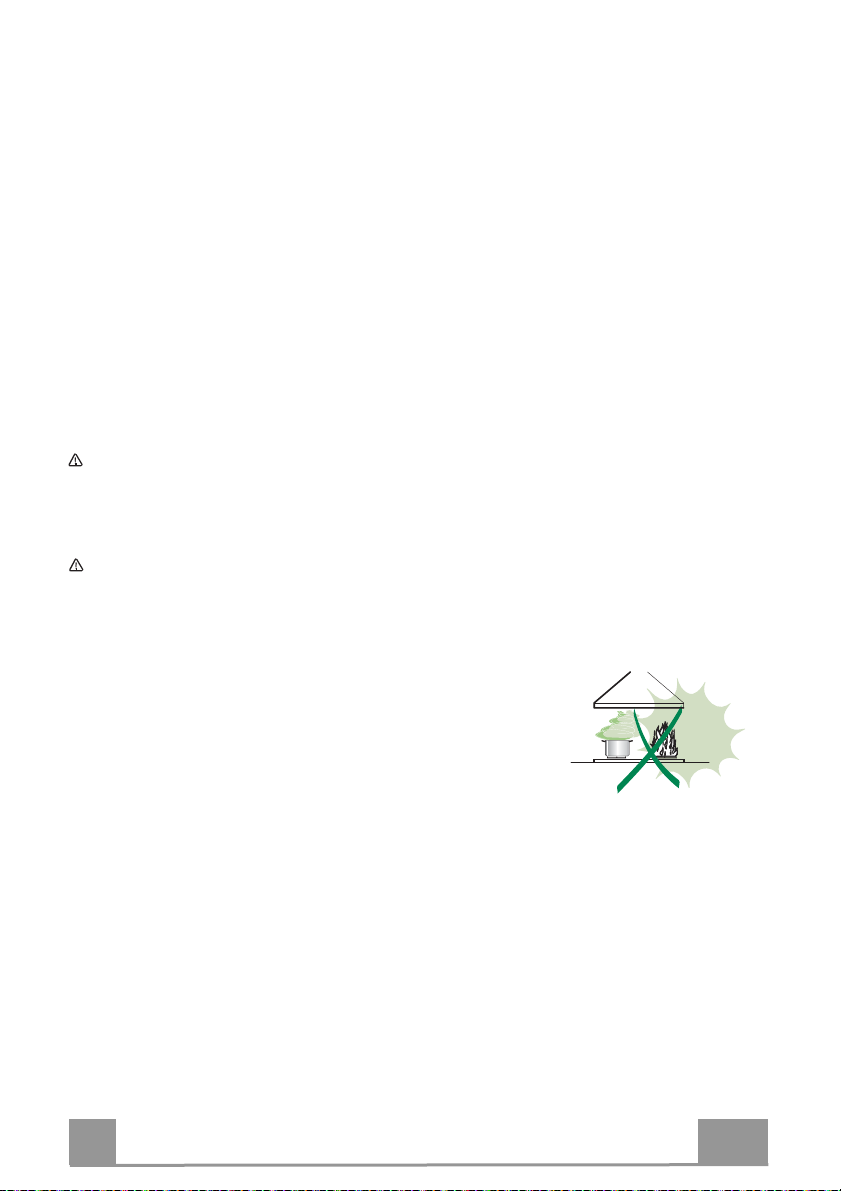
Achtung! Frittiergeräte müssen während des Gebrauchs stets
beaufsichtigt werden: Überhitztes Öl kann sich entzünden.
• Auf keinen Fall unter der Haube flambieren: Brandgefahr.
• Kinder ab 8 Jahren und Personen mit
eingeschränkten physischen, sensorischen oder
psychischen Fähigkeiten, oder mit mangelnden
Erfahrungen oder Kenntnissen dürfen nicht mit
dem Gerät umgehen, es sei denn, sie werden von
einer für ihre Sicherheit verantwortlichen Person
beaufsichtigt oder angeleitet. Sicherstellen, dass Kinder nicht mit dem Gerät
herumspielen können. Reinigungs- und Wartungsarbeiten dürfen nicht von
unbeaufsichtigten Kindern durchgeführt werden.
DE
31
3
Page 32

• ACHTUNG: Die zugänglichen Teile können während des Gebrauchs der
Kochgeräte sehr heiß werden.
WARTUNG
• Vor Reinigungs- oder Wartungsarbeiten am Gerät, muss dieses
ausgeschaltet und spannungslos gemacht werden.
• Die Filter stets nach den angegebenen Intervallen reinigen oder
auswechseln (Brandgefahr).
• Die Fettfilter sind alle 2 Monate oder bei intensiver Nutzung öfter zu reinigen
und können in der Spülmaschine gespült werden.
• Der Aktivkohlefilter ist weder waschbar, noch regenerierbar und muss bei
normalem Betrieb zirka alle 4 Monate oder auch öfter ausgewechselt
werden, je nach Intensität des Gebrauchs.
• „Wenn die Reinigung nicht nach den Anweisungen durchgeführt wird,
besteht Brandgefahr“.
• Die Haube mit einem feuchten Lappen und einem neutralen
Reinigungsmittel abwischen.
Das Symbol am Produkt oder auf der Verpackung weist darauf hin, dass
das Gerät nicht als normaler Hausmüll entsorgt werden darf. Das ausrangierte
Gerät muss vielmehr bei einer speziellen Sammelstelle für elektrische und
elektronische Geräte abgegeben werden. Mit der vorschriftsmäßigen
Entsorgung des Gerätes trägt der Benutzer dazu bei, schädliche
Auswirkungen auf Umwelt und Gesundheit zu vermeiden. Weitere
Informationen zum Recycling dieses Produktes können bei der zuständigen
Behörde, der örtlichen Abfallbeseitigung oder bei dem Händler, der das Gerät
verkauft hat, eingeholt werden.
DE
32
3
Page 33
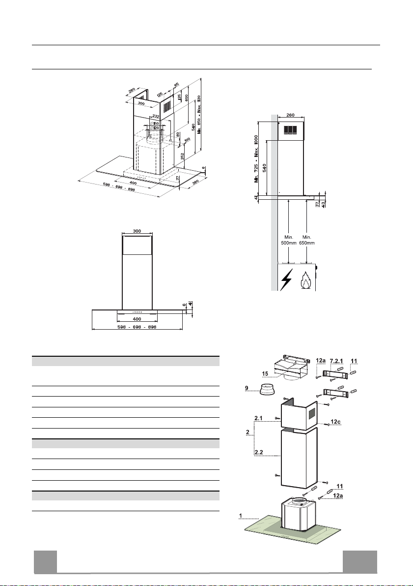
CHARAKTERISTIKEN
Platzbedarf
Komponenten
Pos. St. Produktkomponenten
1 1 Haubenkörper mit Schaltern, Beleuchtung, Geblä-
segruppe, Filter
2 1 Teleskopkamin bestehend aus:
2.1 1 oberer Kaminteil
2.2 1 unterer Kaminteil
9 1 Reduzierflansch ø 150-120 mm
15 1 Luftaustritt-Anschlussstück
Pos. St. Montagekomponenten
7.2.1 2 Befestigungsbügel oberer Kaminteil
11 6 Dübel
12a 6 Schrauben 4,2 x 44,4
12c 6 Schrauben 2,9 x 9,5
St. Dokumentation
1 Bedienungsanleitung
DE
33
3
Page 34
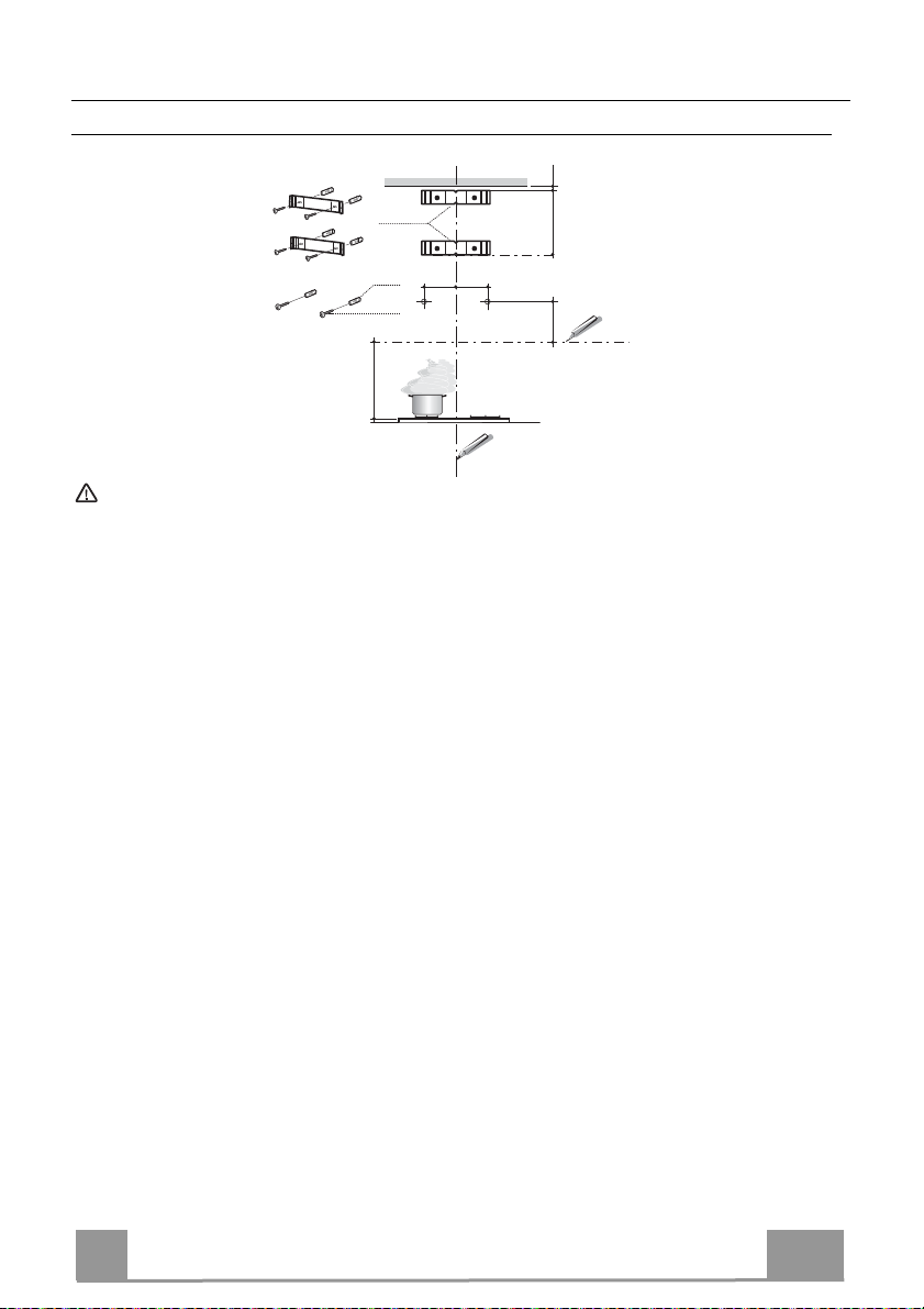
MONTAGE
Bohren der Befestigungslöcher und Fixieren der Befestigungsbügel
1÷2
7.2.1
11
12a
650 min.
Achtung: Bitte beachten Sie bei der Montage das Gewicht der kompletten Haube. Die Tragfähigkeit der
Decke oder alternativ der Trägerplatte für diese Zugbelastung muss vor der Montage geprüft und gegebenenfalls durch die Anbringung von geeigneten Befestigungs- oder Stabilisierungselementen hergestellt
werden. Kann eine hinreichende Tragfähigkeit nicht sichergestellt werden, ist von einer Montage abzusehen.
116
116
X
306
Nachstehende Linien an die Wand zeichnen:
• eine vertikale Linie bis zur Decke oder oberen Begrenzung, und zwar in der Mitte des Bereiches, in dem die Haube montiert werden soll;
• eine horizontale Linie mit einem minimalen Abstand von 650 mm zur Kochfläche.
• Einen Bügel 7.2.1 zirka 1-2 mm unter der Decke oder oberen Begrenzung an die Wand le-
gen und seinen Mittelpunkt (Einschnitte) auf die vertikale Bezugslinie ausrichten.
• Die Mitte der beiden Bügellöcher an der Wand markieren.
• Den zweiten Bügel 7.2.1 an die Wand legen, wobei ein Abstand X mm vom oberen Bügel
einzuhalten ist (X = Höhe des jeweiligen oberen Kaminteils); den Mittelpunkt (Einschnitte)
auf die vertikale Bezugslinie ausrichten.
• Die Mitte der Bügellöcher an der Wand markieren.
• Wie beschrieben einen Bezugspunkt 116 mm von der vertikalen Bezugslinie und 306 mm
oberhalb der horizontalen Bezugslinie kennzeichnen.
• Gleichermaßen an der gegenüberliegenden Seite vorgehen.
• Mit einem Bohrer ø 8 mm die markierten Punkte bohren.
• Die Dübel 11 in die Bohrungen einfügen.
• Die Bügel mit den mitgelieferten Schrauben 12a (4,2 x 44,4) fixieren.
• 2 der mitgelieferten Schrauben 12a (4,2 x 44,4) bei den Befestigungslöchern des Haubenkörpers einschrauben, wobei zwischen Wand und Schraubenkopf ein Freiraum von 5-6 mm
zu belassen ist.
DE
34
3
Page 35
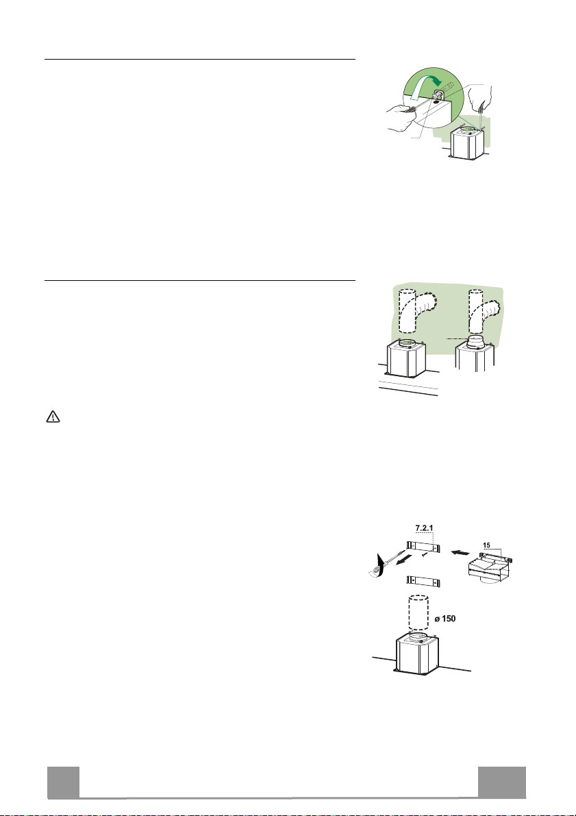
Montage des Haubenkörpers
• Bevor der Haubenkörper eingehakt wird, die 2 Schrauben
Vr bei den Haubenkörper-Anhakpunkten festziehen.
• Den Haubenkörper bei den Schrauben 12a einhängen.
• Die Halteschrauben 12a definitiv festziehen.
• Den Haubenkörper mit Hilfe der Schrauben Vr ausrichten.
Anschluss der Abluftversion
Bei Abluftbetrieb kann die Haube vom Installateur wahlweise
mittels Rohr oder Schlauch (ø 150 oder 120 mm) an die Außenrohrleitung angeschlossen werden.
• Bei Verwendung eines Anschlussrohres ø 120 den Reduzierflansch 9 am Haubenaustritt anbringen.
• Das Rohr mit geeigneten Rohrschellen fixieren. Das hierzu
erforderliche Material wird nicht mitgeliefert.
• Eventuell vorhandene Aktivkohlefilter entnehmen.
Achtung! Alle Querschnittänderungen oder Richtungsänderungen des Abluftkanals reduzieren die Leistung der Haube.
Vr
12a
ø 120ø 150
9
LUFTAUSTRITT BEI DER UMLUFTVERSION
• Die beiden Befestigungsschrauben des oberen Bügels
7.2.1. aufschrauben.
• An ihrer Stelle mit den zuvor entfernten Schrauben ein
Anschlussstück an die Abzugsöffnung 15 anschrauben.
• Den Anschluss 15 mittels eines starren oder flexiblen
Rohrs mit ø150 mm, das vom Installateur ausgewählt wird,
an den Austritt des Haubenkörpers anschließen.
• Sicherstellen, dass der Aktivkohlefilter zur
Geruchsbindung vorhanden ist.
DE
35
3
Page 36
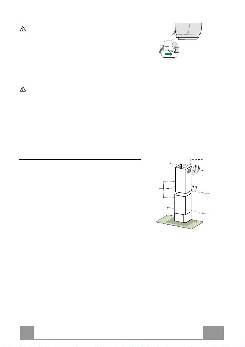
Elektroanschluss
Vor der Installation die Netzspannung durch heraus-
drehen der Sicherung oder ausschalten des Haupt-
schalters stromlos machen.
• Bei Anschluss der Haube an das Stromnetz muss
ein zweipoliger Schalter mit einem Öffnungsweg
von mindestens 3 mm zwischengeschaltet werden.
• Entfernen Sie die Fettfilter (s. Abschnitt „War-
tung“) und versichern Sie sich, daß die Kabelver-
bindung in die Steckdose des Gebläses einwandfrei
eingesteckt wird.
Achtung: Das Gerät nur an die Netzspannung die im
Typenschild angegeben ist anschließen.
Kaminmontage
Oberer Kaminteil
• Die beiden seitlichen Schenkel leicht auseinanderbie-
gen, hinter den Bügeln 7.2.1 einhängen und bis zum
Anschlag wieder schließen.
• Bei den Bügeln 7.2.1 mit Hilfe der 4 mitgelieferten
Schrauben 12c fixieren.
• Überprüfen, ob die Verlängerungen mit den entspre-
chenden Kaminstutzen übereinstimmen.
Unterer Kaminteil
• Die beiden seitlichen Schenkel des Kaminteils leicht
auseinander biegen, zwischen dem oberen Kaminteil
und der Wand einhängen und bis zum Anschlag wieder schließen.
• Den unteren Teil seitlich am Haubenkörper mit 2 der
mitgelieferten Schrauben 12c fixieren.
7.2.1
12c
2.1
2
2.2
12c
12c
DE
36
3
Page 37
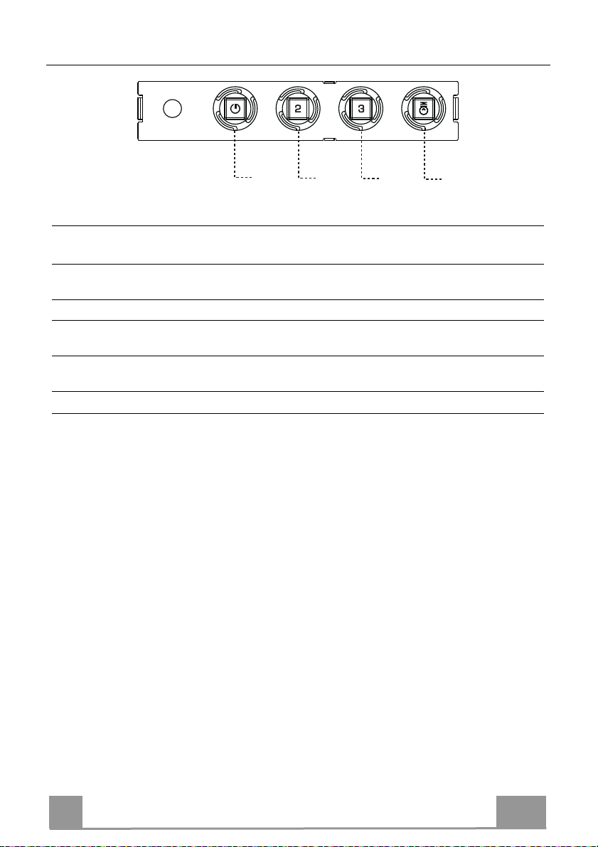
BEDIENUNG
T1
LED FUNKTIONEN
TASTE
T1 Betriebsgeschwindigkeit Eingeschaltet Schaltet den Motor bei der ersten
T2 Betriebsgeschwindigkeit Eingeschaltet Schaltet den Motor bei der zweiten
T3 Betriebsgeschwindigkeit Bleibend Schaltet den Motor bei der dritten
L Licht Schaltet die Beleuchtung ein und aus.
Achtung: Mit der Taste T1 wird von der ersten Betriebsgeschwindigkeit aus der Motor
abgestellt.
T2
Schalttafel
Betriebsgeschwindigkeit ein.
Stellt den Motor ab.
Betriebsgeschwindigkeit ein.
Betriebsgeschwindigkeit ein.
T3
L
DE
37
3
Page 38
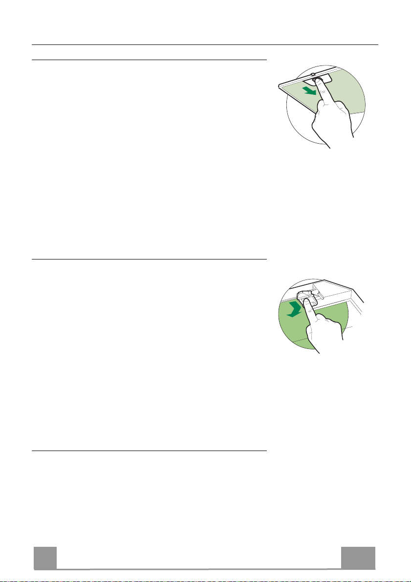
WARTUNG
Fettfilter
SELBSTTRAGENDER METALLFETTFILTER REINIGUNG
• Sie müssen nach 2-monatigem Betrieb bzw. bei starkem Ein-
satz auch häufiger gereinigt werden, was im Geschirrspüler
möglich ist.
• Die Filter nacheinander aushaken, indem sie auf die Rückseite
der Gruppe geschoben und gleichzeitig nach unten gezogen
werden.
• Die Filter reinigen (darauf achten, sie nicht zu verbiegen) und
vor der Remontage trocknen lassen.
• Bei der Remontage ist darauf zu achten, dass sich der Griff auf
der sichtbaren Außenseite befindet.
Geruchsfilter (Umluftversion)
AUSTAUSCHEN DER AKTIVKOHLE FILTER
• Dieser Filter kann weder gewaschen noch wiederverwendet
werden und ist alle 4 Betriebsmonate bzw. bei starkem Einsatz
auch häufiger auszutauschen.
• Die Metallfettfilter entfernen.
• Den gesättigten Aktivkohle-Filter aushaken.
• Den neuen Filter in seinem Sitz einhaken.
• Die Metallfettfilter wieder montieren.
Beleuchtung
LED-Strahler
• Für den Austausch der LED-Strahler wenden Sie sich bitte an den
Kundendienst.
DE
38
3
Page 39
TAVSİYELER VE ÖNERİLER
Kullanım talimatları, bu ev aletinin çeşitli modelleri için geçerlidir. Aynı
şekilde, bu ürünle ilgisi olmayan özelliklerin tanımlarını da görebilirsiniz.
MONTAJ
• Yanlış veya hatalı montajdan doğan yaralanma ve hasarlar için imalatçı
yükümlü olmayacaktır.
• Pişiricinin üst kısmı ve davlumbaz arasındaki minimum
güvenlik mesafesi 650 mm'dir. (Bazı modeller daha
alçak mesafeye monte edilebilir, lütfen çalışma
boyutları ve montaj paragraflarına bakınız.)
• Ana voltajın davlumbazın iç tarafına sabitlenmiş olan
derecelendirme plakasındaki ile uyumlu olduğunu
kontrol edin.
• I. sınıf ev aletleri için, ev güç kaynağının yeterli topraklama sağladığından
emin olun.
Aspiratörü egzoz bacasına minimum çapı 120 mm olan bir boru vasıtasıyla
bağlayın. Baca hattı mümkün olduğu kadar kısa olmalıdır.
• Davlumbazı tutuşabilir gazlar taşıyan egzoz kanallarına bağlamayın
(kazanlar, şömineler, vs.).
• Eğer davlumbaz elektrikli olmayan ev aletleri ile birlikte
kullanılacaksa (ör. gazlı ev aletleri), egzoz gazının geri
tepmesini engellemek adına odada yeterli derecede bir
havalandırma olması garanti edilmelidir. Temiz havanın
girişini garanti etmek adına mutfakta temiz hava girişini
sağlayan bir açıklık olmalıdır. Davlumbazın elektrik
dışında enerji veren ev aletleri ile birlikte kullanılması
durumunda, davlumbazın gazları geri yollamasını engellemek adına odadaki
negatif basınç 0,04 barı aşmamalıdır.
• Güç kablosuna zarar gelmesi durumunda, herhangi bir riski engellemek
adına imalatçı veya teknik servis birimince değiştirilmelidir.
• Hava, gaz veya başka yakıtların tahliyesi için kullanılan borulara deşarj
edilmemelidir (havayı sadece odaya tahliye eden ev aletleri için geçerli
değildir).
2°
TR
39
3
Page 40
• Gaz ocağının montaj talimatlarında yukarıda belirtilenden daha fazla bir
mesafe belirtilmişse, buna dikkat edilmesi gerekir. Hava deşarjı ile ilgili
yönetmeliklere uyulması gerekir.
• Davlumbazı desteklemek için sadece vida ve küçük parçalar kullanın.
Uyarı: İşbu talimatlar uyarınca vidaları veya sabitleme aletlerini
kullanmamak elektrik tehlikelerine yol açabilir.
• Davlumbazı, arasında en az 3mm irtibat mesafesi olan iki kutuplu bir anahtar
vasıtasıyla cereyana bağlayın.
KULLANIM
• Davlumbaz mutfak kokularını gidermek adına ev kullanımı için
tasarlanmıştır.
• Davlumbazı asla tasarlandığı amaçlar haricinde kullanmayın.
• Davlumbaz çalışırken altında boşuna yanan yüksek ateş asla bırakmayın.
• Ateş yoğunluğunu sadece tencere altında kalacak ve yanlardan
taşmadığından emin olacak şekilde ayarlayın.
• Fritözler kullanım esnasında sürekli izlenmelidir:
fazla ısınmış yağ, ateş alabilir.
• Davlumbaz altında flambe yapmayınız; yangın
riski.
• Bu ev aleti, 8 yaş üstü çocuklar ve fiziksel,
duyusal veya akli yetersizliği olan veya tecrübe ve
bilgi eksikliği olan kişilerce bu kişilerin güvenliğinden sorumlu olan kişilerin
gözetimi altında veya ev aletinin kullanımı ile ilgili talimatlar kendilerine
verildiği durumlarda kullanılabilir. Çocuklar, ev aleti ile oynamamalıdır.
Temizleme ve bakım gözetimde olmadıklarında çocuklarca yapılmayacaktır.
TR
40
4
Page 41

• “DİKKAT: Pişirme aletleri ile kullanıldıklarında temas edilebilir parçalar
ısınabilir.”
BAKIM
• Herhangi bir bakım işlemine başlamadan evvel ev aletini kapatın veya ana
güç kaynağından fişini çekin.
• Belirlenmiş zaman sonunda filtreleri temizleyin ve/veya değiştirin (Yangın
tehlikesi).
• Yağ filtreleri her 2 ayda bir veya yoğun kullanım olması durumunda daha sık
olarak temizlenmelidir ve bulaşık makinesinde yıkanabilirler.
• Aktif karbon filtresi yıkanabilir değildir, yeniden kullanılamaz ve her 4 ayda
bir veya yoğun kullanım olması durumunda daha sık olarak değiştirilmelidir.
• "Temizliğin talimatlara uygun olarak yapılmadığı durumlarda yangın riski
vardır."
• Davlumbazı nemli bir bez ve nötr sıvı deterjanla temizleyin.
Ürün üstündeki veya paketindeki sembolü, bu ürünün evsel atık olarak
değerlendirilmeyeceğinin göstergesidir. Elektrikli ve elektronik ekipmanın geri
dönüşümü için uygun toplama noktasına teslim edilmelidir. Bu ürünün doğru
şekilde bertaraf edildiğinden emin olarak, bu atık ürününün uygun olmayan
şekilde işlenmesinden doğacak çevre ve insan sağlığı için potansiyel olumsuz
sonuçların engellenmesine yardımcı olacaksınız. Bu ürünün geri dönüşümü ile
ilgili daha detaylı bilgi için lütfen yerel yetkili ofisiniz, evsel atık bertaraf hizmeti
veya ürünü satın aldığınız mağaza ile irtibata geçiniz.
TR
41
4
Page 42
ÖZELLIKLER
Boyutlar
Parçalar
Ref. Adet Ürünün parçaları
1 1 Şunlardan oluşan davlumbaz gövdesi: Kumandalar,
Lamba, Fan grubu, Filtreler
2 1 Şunlardan oluşan teleskopik baca:
2.1 1 Üst baca
2.2 1 Alt baca
9 1 Redüksiyon Flanşı ø 150-120 mm
15 1 Hava Çıkışı Rakoru
Ref. Adet Montaj Parçaları
7.2.1 2 Üst Baca Tesbit Braketleri
11 6 Dübeller
12a 6 Vidalar 4,2 x 44,4
12c 6 Vidalar 2,9 x 9,5
Adet Belgeler
1 Talimat Kılavuzu
TR
42
4
Page 43
MONTAJ
Duvarın delinmesi ve takozların sabitlenmesi
7.2.1
11
12a
116
116
650 min.
Duvarın üzerinde:
• üst sınıra veya tavana kadar dik bir çizgi çiziniz; çizgi, bacanın yerleştirileceği bölgenin or-
tasından geçmelidir;
• Pişirme düzleminin 650 mm. üzerinden geçecek şekilde yere paralel bir çizgi çiziniz.
• gösterildiği üzere 7.2.1 no.lu takozu tavandan veya üst sınırdan 1-2 mm aşağısına yerleştire-
rek merkezinin dik referans çizgisinin üzerinde olmasına dikkat ediniz.
• Takozun deliklerinin merkezlerini işaretleyiniz.
• Şekilde gösterildiği üzere 7.2.1 no.lu takozu birinci takozun X mm altına yerleştiriniz (X =
kullanılacak üst bacanın yüksekliği). merkezinin dik referans çizgisinin üzerinde olmasına
dikkat ediniz.
• Takozun deliklerinin merkezlerini işaretleyiniz.
• Şekilde görüldüğü üzere dik çizginin 116 mm açığında ve yatay çizginin 306 mm üzerinde
bir referans noktası tespit ediniz.
• Aynı işlemi diğer tarafa uygulayınız.
• Tespit edilen noktaları
ø 8 mm ile deliniz.
• Deliklere 11 no.lu destekleri yerleştiriniz
• 12a no.lu vidaları (4,2 x 44,4 ) kullanarak takozları monte ediniz.
• 2 adet 12a (4,2 x 44,4) vidasını baca gövdesi sabitleme yuvalarına yerleştiriniz. Duvar ile
vida başı arasında 5-6 mm’lik mesafe bırakınız.
1÷2
X
306
TR
43
4
Page 44
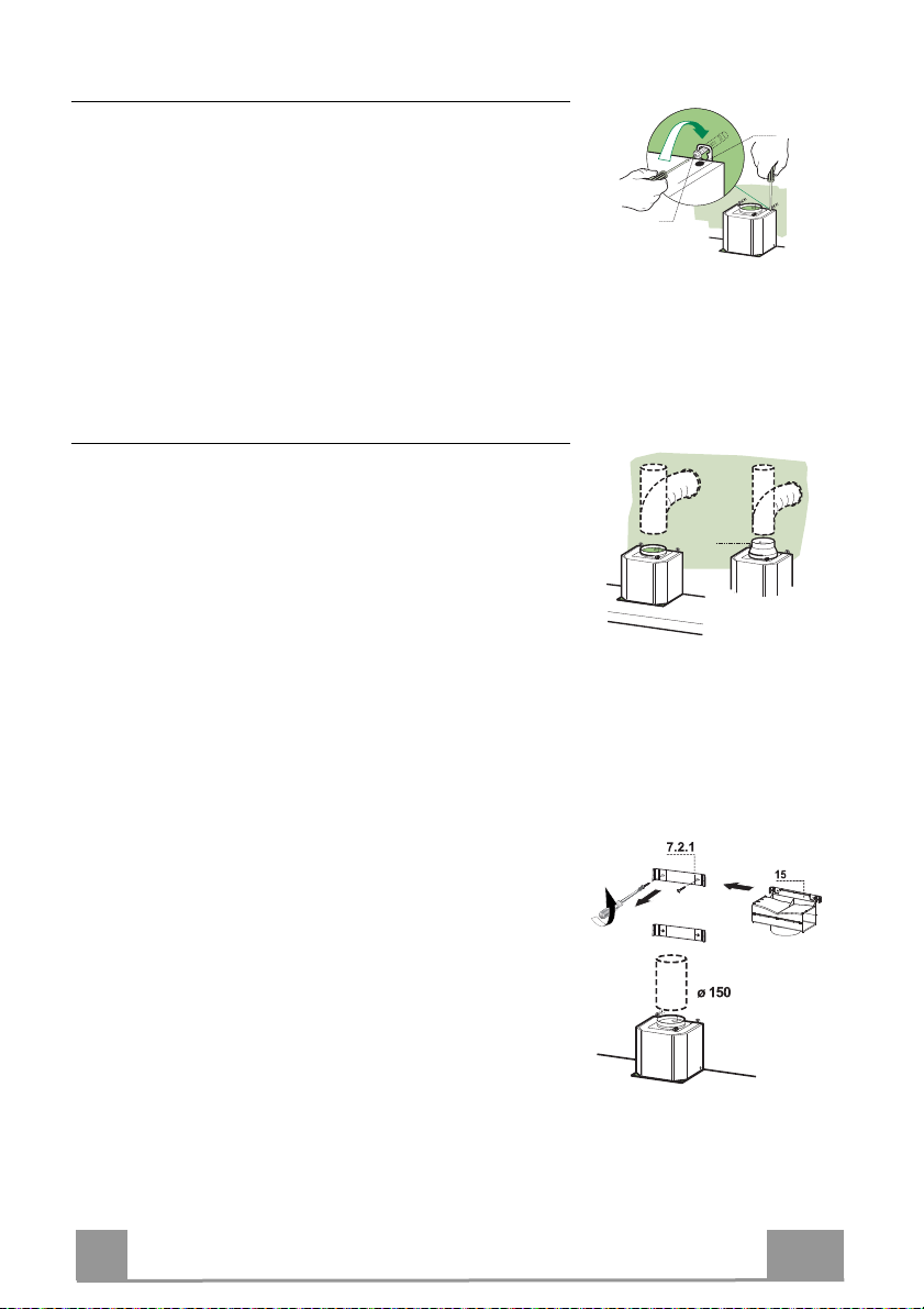
Davlumbaz Gövdesi Montajı
• Davlumbaz Gövdesini kancalara takmadadan önce gövde
üzerindeki kancalama noktalarında bulunan 2 adet vidayı
Vr sıkınız.
• Davlumbaz Gövdesini vidalara 12a takınız.
• Destek vidalarını 12a nihai olarak sıkınız.
• Vr vidalarına müdahale ederek Davlumbaz Gövdesi sevi-
yesini hizalayınız.
Bağlantılar
ASPİRATÖRLÜ MODEL HAVA ÇIKIŞI
Aspiratörlü modelin montajı için, davlumbaz, montörün seçeceği 150 yada 120 mm çapında sert veya esnek bir boru ile
çıkış kanalına bağlanmalıdır.
• ø120 mm çapında boru ile bağlantı için, redüksiyon flanşını
(9) davlumbaz gövdesi çıkışına yerleştiriniz.
• Boruyu uygun kelepçelerle sıkarak sabitleyiniz. Bu malze-
me davlumbaz donanımıyla birlikte verilmemiştir.
• Varsa aktif karbonlu koku alma filtrelerini çıkarınız.
Vr
12a
ø 120ø 150
9
FİLTRELİ SİSTEMDE HAVA ÇIKIŞI
• Alt askıyı 7.2.1 sabitleyen iki vidayı yerinden sökünüz.
• Hava Çıkış Bağlantısını 15 daha önceden çıkarılmış olan 2
vida ile yerine sabitleyin.
• 15 no.lu Bağlantıyı, montaj görevlisinin seçimine göre
ø150 mm çapında sert veya esnek bir hortum ile
Davlumbaz Gövdesi Çıkışına bağlayınız.
• Aktif Karbonlu Koku önleyici Filtrenin bulunduğundan
emin olunuz.
TR
44
4
Page 45
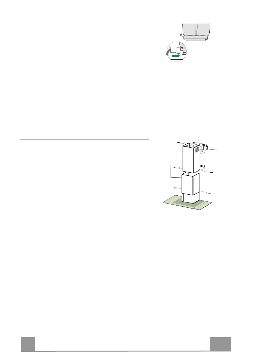
ELEKTRİK BAĞLANTISI
• Davlumbazı şebeke cereyanına bağlarken aray temas
aralığı en az 3 mm olan çift kutuplu bir elektrik anahtarı
koyunuz.
• Yağ tutucu filtreleri çıkarınız (bakınız "Bakım" paragra-
fı) ve besleme kablosu soketinin aspiratör prizine iyice
takılmış olduğundan emin olunuz.
Bacanın montajı
Üst baca
• İki yan kenarı hafifçe açınız, bunları braketlerin 7.2.1
arkasına geçiriniz ve tam dayanana kadar tekrar kapatı-
nız.
• Cihaz donanımında verilen 4 adet vidayla 12c (2,9 x
9,5) yan taraflarından braketlere sabitleyiniz.
• Rakor uzantılarının çıkışının baca ağızlarına denk gel-
mesine dikkat ediniz.
Alt baca
• Bacanın iki yan kenarını hafifçe açınız, Üst baca ile du-
var arasına geçirip tam dayanana kadar kapatınız.
• Cihaz donanımında verilen 2 adet vidayla 12c (2,9 x
9,5) alt tarafını davlumbaz gövdesine sabitleyiniz.
7.2.1
12c
2.1
2
2.2
12c
12c
TR
45
4
Page 46
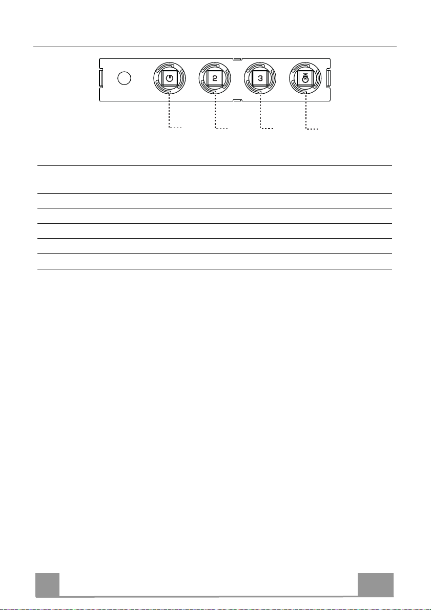
KULLANIM
T1
Kumanda Tablosu
TUŞ LED
T1 Hız Açık Birinci hızda motoru çalıştırır.
T2 Hız Açık İkinci hızda motoru çalıştırır.
T3 Hız Sabit Hafifçe basılınca, üçüncü hızda motoru çalıştırır.
L Işık Işık tesisatını açıp kapatır.
Dikkat: T1 tuşu daima ilk hızdan geçerek motoru durdurur.
FONKSİYON
Motoru durduruyor.
T2
T3
L
TR
46
4
Page 47
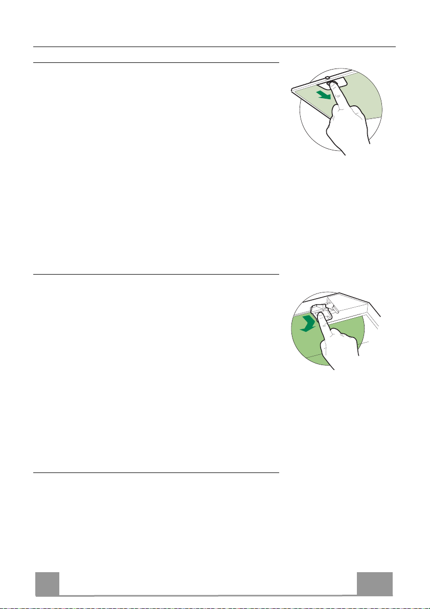
BAKIM
Yağ tutucu filtreler
METALİK YAĞ TUTUCU FİLTRELERİN TEMİZLENMESİ
• Bu filtreler bulaşık makinasında da yıkanabilir ve normal kul-
lanıldıklarında iki ayda bir, yoğun kullanım halinde ise daha
sıkça yıkanmalarıı gereklidir.
• Filtrleri, grubun arka tarafından ittirerek ve aynı anda aşağı
doğru çekerek tek tek çıkarınız.
• Filtreleri yıkarken eğip katlamayınız, tekrar monte etmeden
önce de kurutunuz.
• Monte ederken kulpun görünen dış tarafa doğru gelmesine dik-
kat ediniz.
Koku Filtresi (Filtreli Model)
AKTİF KARBONLU KOKU FİLTRESİNİN DEĞİŞTİRİLMESİ
• Yıkanabilir ya da rejenere edilebilir nitelikte değildir, normalde
en az 4 ayda bir, yoğun kullanımda ise daha sıkça değiştirilir.
• Metalik Yağ Filtrelerini çıkarınız.
• Doymuş durumdaki Aktif Karbonlu Koku Filtresini kancalarını
serbest bırakarak çıkarınız.
• Yeni filtreyi yuvasına takınız.
• Metalik Yağ Filtrelerini tekrar monte ediniz.
Aydınlatma
• Değiştirmek için Teknik Servisle bağlantı kurun ("Edinmek
için teknik servisle bağlantı kurun").
TR
47
4
Page 48
UWAGI I SUGESTIE
Instrukcja obsługi dotyczy różnych modeli niniejszego urządzenia. Dlatego też
w niektórych jej miejscach można znaleźć opisy, które nie dotyczą tego
konkretnego urządzenia.
MONTAŻ
• Producent nie ponosi odpowiedzialności za ewentualne
szkody spowodowane przez nieprawidłową instalację lub
użytkowanie.
• Minimalna bezpieczna odległość od powierzchni gotowania do
krawędzi okapu powinna wynosić co najmniej 650 mm
(niektóre modele mogą zostać zainstalowane niżej; patrz
odpowiedni rozdział zawierający wymiary robocze i montażowe).
• Sprawdzić, czy napięcie w sieci elektrycznej odpowiada danym umieszczonym na
tabliczce znamionowej znajdującej się wewnątrz okapu.
• Dla urządzeń klasy I należy sprawdzić, czy sieć elektryczna wyposażona jest w
odpowiednie uziemienie.
Podłączyć wyciąg do komina dymnego przy pomocy rury o średnicy minimalnej
120 mm. Trasa rury powinna być możliwie najkrótsza.
• Okapu nie należy podłączać do kanałów dymowych, przez które odprowadzane
są dymy powstające na skutek spalania (na przykład z grzejników, kominów).
• Jeżeli okap używany jest w połączeniu z kuchenkami nieelektrycznymi (np.
gazowymi), należy zagwarantować odpowiedni poziom wentylacji lokalu tak, aby
zapobiec powrotowi spalin z komina. Kuchnia musi mieć otwór wentylacyjny
bezpośrednio na zewnątrz tak, aby zapewnić dopływ świeżego
powietrza. Jeżeli okap używany jest w połączeniu z kuchenkami
nieelektrycznymi, podciśnienie w pomieszczeniu nie może
przekraczać 0,04 mbar, aby zapobiec powrotowi spalin.
• Powietrze nie może być odprowadzane przez rurę elastyczną
używaną do odprowadzania spalin z urządzeń zasilanych gazem lub innymi
paliwami (nie używać z urządzeniami, które pobierają powietrze z
pomieszczenia).
• Jeżeli kabel zasilający zostanie uszkodzony, w celu uniknięcia sytuacji zagrożenia
powinien zostać wymieniony przez producenta lub wykwalifikowanych
pracowników serwisu.
2°
PL
48
4
Page 49
• Jeśli instrukcja instalacji kuchenki gazowej wskazuje na potrzebę
zastosowana większej odległości, niż podana powyżej, należy to wziąć pod
uwagę. Należy przestrzegać wszystkich norm dotyczących odprowadzania
powietrza.
• Używać wyłącznie śrub oraz osprzętu typu odpowiedniego dla danego
okapu. Ostrzeżenie: brak śrub lub elementu osprzętu zgodnych z instrukcją
może być przyczyną porażenia prądem.
• Przyłączyć okap do sieci zasilającej, montując wyłącznik dwubiegunowy o
otwarciu styków co najmniej 3 mm.
UŻYTKOWANIE
• Okap został zaprojektowany wyłącznie do użytku domowego, do eliminacji
zapachów kuchennych.
• Nie wolno nigdy używać okapu do celów innych niż te, do których został
zaprojektowany.
• Nie wolno nigdy pozostawiać wolnego ognia o dużej intensywności pod
działającym okapem.
• Należy dokonać regulacji intensywności płomienia w taki sposób, aby
znajdował się wyłącznie pod naczyniem do gotowania i nie wydostawał się z
jego boków.
• Nie zostawiać naczyń do smażenia bez nadzoru
podczas użycia: przegrzany olej może się zapalić.
• Nie zapalać potraw pod okapem: może to być
przyczyną pożaru.
• Niniejsze urządzenie może być używane przez
dzieci w wieku poniżej 8 lat oraz osoby
niepełnosprawne fizycznie lub umysłowo oraz bez doświadczenia lub wiedzy
na temat jego działania, powinni oni zostać jednak poinstruowani i
skontrolowani w kwestii obsługi urządzenia przez osoby odpowiedzialne za
ich bezpieczeństwo. Należy pilnować, aby dzieci nie bawiły się urządzeniem.
Czyszczenie i konserwacja urządzenia nie powinny być wykonywane przez
dzieci, chyba że są one nadzorowane.
PL
49
4
Page 50

• „UWAGA: części zewnętrzne mogą stać się bardzo gorące, jeżeli używane
są razem z urządzeniami przeznaczonymi do gotowania”.
KONSERWACJA
• Wyłączyć urządzenie lub odłączyć je od źródła zasilania elektrycznego
przed przystąpieniem do wszelkich prac związanych z czyszczeniem i
konserwacją.
• Umyć i/lub wymienić filtry po określonym czasie (zagrożenie pożarowe).
• Filtry przeciwtłuszczowe należy myć co 2 miesiące lub częściej w razie
użytkowania intensywnego, można je myć w zmywarce.
• Filtry z węgla aktywnego nie są przeznaczone do mycia ani regeneracji i
należy je wymieniać co około 4 miesiące użytkowania lub częściej, jeśli
używane są bardzo intensywnie.
• „Istnieje ryzyko pożaru, jeżeli czyszczenie nie będzie przeprowadzane
zgodnie ze wskazówkami”.
• Zaleca się czyszczenie okapu przy pomocy wilgotnej ściereczki i neutralnego
płynu do mycia.
Symbol znajdujący się na urządzeniu lub na jego opakowaniu oznacza, że
nie wolno danego urządzenia wyrzucać razem ze zwykłymi odpadami
domowymi. Zużyty produkt należy przekazać do centrum zbiórki odpadów,
specjalizującego się w recyklingu komponentów elektrycznych i
elektronicznych. Likwidując produkt w sposób właściwy, przyczyniasz się do
zapobiegania ewentualnym ujemnym wpływom na środowisko naturalne oraz
na zdrowie ludzi, które mogłyby powstać w wyniku niewłaściwej likwidacji.
Szczegółowe informacje na temat recyklingu tego produktu można uzyskać w
urzędzie miasta/ gminy, lokalnych instytucjach zajmujących się likwidacją
odpadów lub w sklepie, w którym produkt został zakupiony.
PL
50
5
Page 51
WŁAŚCIWOŚCI TECHNICZNE
Wymiary
Części
L.p. Ilość Części okapu
1 1 Korpus okapu razem z: Włącznikami, Oświetleniem,
Dmuchawą, Filtrami
2 1 Teleskopowa osłona przewodu kominowego:
2.1 1 Część górna
2.2 1 Część dolna
9 1 Kołnierz redukujący o średnicy 150-120 mm
15 1 Łącznik odpływu powietrza
L.p. Ilość Części montażowe
7.2.1 2 Wsporniki mocujące górnej części osłony przewodu
kominowego
11 6 Kołki rozporowe
12a 6 Wkręty 4,2 x 44,4
12c 6 Wkręty 2,9 x 9,5
Ilość Dokumentacja
1 Instrukcja obsługi
PL
51
5
Page 52
INSTALACJA
Wiercenie i mocowanie elementów montażowych
1÷2
7.2.1
11
116
116
12a
650 min.
sować na ścianie:
Nary
• w środku strefy przewidzianej na montaż okapu linię pionową aż do sufitu lub do górnej
granicy.
• linię poziomą: 650 mm ponad poziomem kuchenki.
• Położyć element montażowy 7.2.1 w odległości 1-2 mm od sufitu lub od powierzchni gór-
nej, centrując go (nacięcie) na linii pionowej odniesienia.
• Zaznaczyć otwory el. montażowego.
• Położyć el. montażowy 7.2.1 w odległości X mm poniżej pierwszego elementu (X = wyso-
kość komina górnego) centrując go (nacięcie) na linii pionowej odniesienia.
• Zaznaczyć otwory el. montażowego.
• Zaznaczyć, tak jak to pokazano na rysunku, punkt odniesienia w odległości 116 mm od linii
pionowej oraz 306 mm powyżej linii poziomej.
• Powtórzyć tę czynność po przeciwnej stronie.
• Wywiercić otwory ø 8 mm w zaznaczonych miejscach.
• Włożyć kołki 11 w otwory.
• Przykręcić elementy montażowe, przy pomocy śrub 12a (4,2 x 44,4 ) znajdujących się na
wyposażeniu.
• Wkręcić 2 śruby 12a (4,2 x 44,4) znajdujące się na wyposażeniu w otwory montażowe kor-
pusu okapu, pozostawiając miejsce 5-6 mm pomiędzy ścianą a główką śruby.
X
306
PL
52
5
Page 53
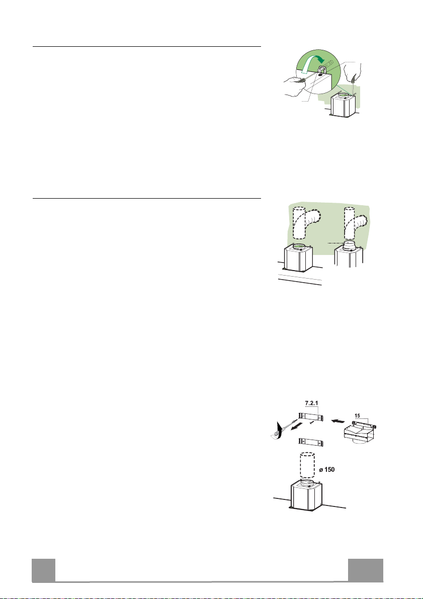
Montaż korpusu okapu
• Przed przystąpieniem do montażu korpusu, należy dokręcić
dwa wkręty Vr znajdujące się w jego punktach montażo-
wych.
• Zawiesić korpus okapu na wkrętach 12a.
• Dokręcić wkręty wspomagające 12a.
• Wyregulować wkręty Vr w celu wypoziomowania korpusu
okapu.
Podłączenia
SYSTEM WENTYLACJI W TRYBIE CYRKULACJI ZEWNĘTRZNEJ
W przypadku montażu w wersji z odprowadzeniem powietrza
na zewnątrz należy podłączyć okap do komina za pomocą
giętkiej lub sztywnej rury o średnicy 150 lub 120 mm. Wybór
opcji należy do montażysty.
• W celu zamontowania wylotu o średnicy 120 mm należy
założyć kołnierz redukujący 9 na wylot powietrza znajdujący się w korpusie okapu.
• Zamocować rurę za pomocą odpowiednich klamer zaci-
skowych do rur (nie znajdują się w zestawie).
• Usunąć filtry węglowe (jeżeli są zamontowane).
Vr
12a
ø 120ø 150
9
WYLOT POWIETRZA - WERSJA Z FILTREM
• Odkręcić 2 śruby mocujące górny element montażowy
7.2.1.
• Przykręcić na miejscu złącze wylotu powietrza 15 przy
pomocy 2 wcześniej wykręconych śrub.
• Połączyć złącze 15 z wylotem obudowy okapu p rzy po-
mocy rury sztywnej lub giętkiej ø 150 mm - wyboru dokonuje instalator.
• Upewnić się czy jest założony węglowy filtr anty-
zapachowy.
PL
53
Page 54
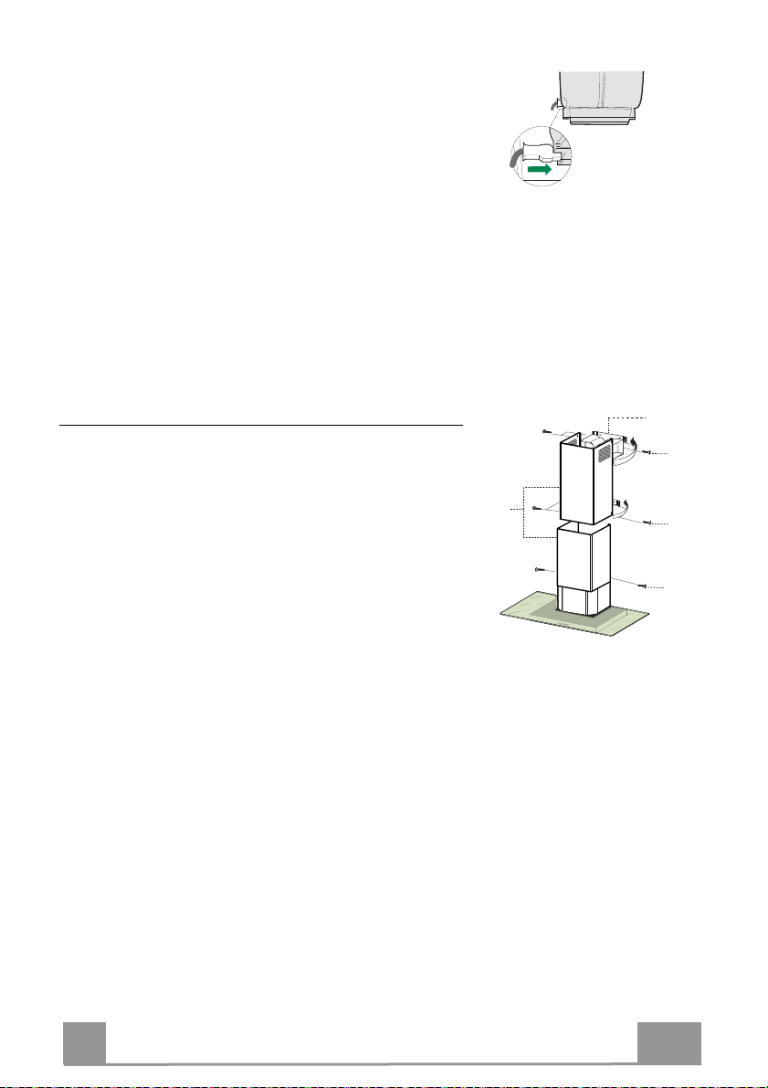
PODŁĄCZENIE DO SIECI ELEKTRYCZNEJ
• Podłączyć okap do sieci elektrycznej za pośrednictwem
dwubiegunowego włącznika o minimalnej rozwartości
styków wynoszącej 3mm.
• Wymontować filtry tłuszczowe i upewnić się, czy wtyk
przewodu zasilającego jest właściwie osadzony w gnieź-
dzie znajdującym się w obudowie wentylatora.
Montaż osłony przewodu kominowego
Część górna
• Należy delikatnie odgiąć boki części osłony i zaczepić je
o wsporniki 7.2.1, upewniając się, że zostały dobrze osadzone.
• Przymocować boki do wsporników używając 4 załączo-
nych wkrętów 12c (2,9 x 9,5).
• Upewnić się, że otwory osłony są wyrównane z odpły-
wami powietrza.
Część dolna
• Delikatnie odgiąć boki osłony i zaczepić je pomiędzy jej
górną częścią, a ścianą, upewniając się, że zostały dobrze
osadzone.
• Zamontować dolną część do korpusu okapu, używając 2
załączonych wkrętów 12c (2,9
x 9,5).
7.2.1
12c
2.1
2
2.2
12c
12c
PL
54
5
Page 55
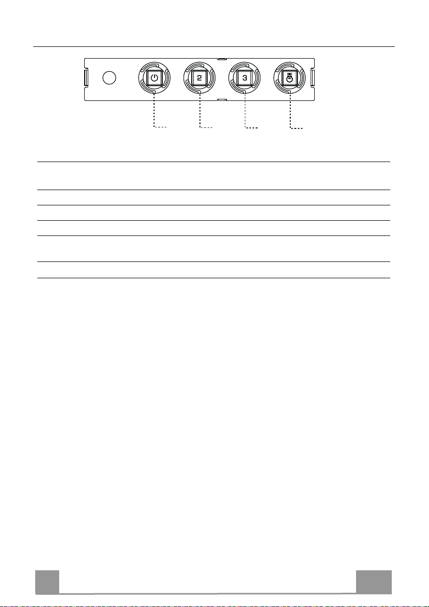
UŻYTKOWANIE
T1
ZYCISK DIODA FUNKCJE
PR
T1 Prędkość Włączona Uruchomienie silnika z pierwszą prędkością.
Wyłączanie silnika.
T2 Prędkość Włączona Uruchomienie silnika z drugą prędkością.
T3 Prędkość Stała Krótkie naciśnięcie powoduje uruchomienie silnika z trzecią
prędkością
L Oświetlenie Włączanie i wyłączanie oświetlenia.
Uwaga: Przycisk T1 wyłącza silnik, przechodząc zawsze przez pierwszą prędkość.
T2
Panel sterowania
T3
L
PL
55
5
Page 56
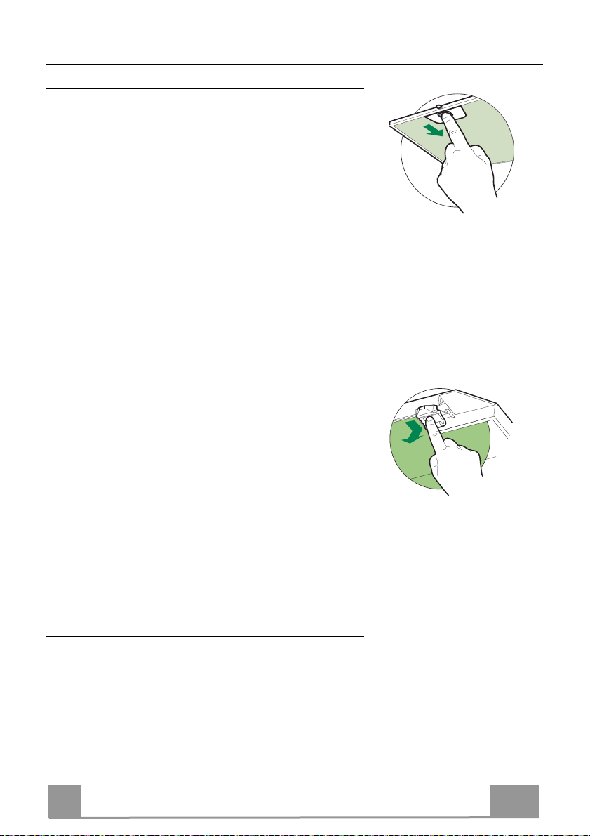
KONSERWACJA
Filtry tłuszczowe
CZYSZCZENIE METALOWYCH, SAMONOŚNYCH FILTRÓW
TŁUSZCZOWYCH
• Filtry należy czyścić co 2 miesiące użytkowania, bądź częściej w
zypadku intensywnego używania. Możliwe jest czys
pr
w z
mywarce.
• Należy zdej
kier
• Unikać zaginania filtrów podczas
żem wewnątrz okapu, upewnić się, czy są całkowicie su
• W
kładając filtry z powrotem do okapu należy zwrócić uwagę,
zostały
mować filtry po kolei, przesuwając ich uchwyty
unku tyłu, jednocześnie pociągając ku dołowi.
mycia. Przed ponownym monta-
poprawnie zamontowane uchwytem do zewną
Filtr węglowy (tryb recyrkulacji)
WYMIANA FILTRA WĘGLOWEGO
• Tego filtra nie można myć ani regenerować. Należy go
wymieniać mniej więcej co 4 miesiące użytkowania lub
częściej w przypadku intensywnego używania.
• Wyjąć metalowe filtry tłuszczowe.
• Wyjąć nasycony filtr węglowy poprzez zwolnienie blokad.
• Włożyć nowy filtr i zamontować w odpowiednim położe-
niu.
• Zamontować ponownie metalowe filtry tłuszczowe.
zczenie ich
che.
aby
trz.
w
Oświetlenie
• W celu wymiany diody należy skontaktować się z
technicznym działem Obsługi Klienta („W celu nabycia
diody należy skontaktować się z technicznym działem
Obsługi Klienta”).
PL
56
5
5
Page 57

Page 58

Page 59

Page 60

Franke S.p.a.
Via Pignolini,2
37019 Peschiera
www.franke.it
del Garda (VR)
991.0444.083_ver2 - 170209
D002640_01
 Loading...