

Page 1
Instructions for use and installation
Cooker Hood
Vejledning for installation brug og vedligeholdelse
Emhætte
Handbok för installation, användning och underhăll
Spisfläkt
Håndbok for installasjon bruk og vedlikehold
Kjøkkenvifte
Asenn
us-, k
äyttö
-
ja hoito
-
opas
Liesituuletin
FDPA 904 XS ECS
SE
NO
FI
GB
DK
Page 2

EN
2
2
Instructions Manual
INDEX
RECOMMENDATIONS AND SUGGESTIONS......................................................................................................................7
CHARACTERISTICS..............................................................................................................................................................8
INSTALLATION ......................................................................................................................................................................9
USE.......................................................................................................................................................................................13
MAINTENANCE....................................................................................................................................................................14
EASY CLEANING TM...........................................................................................................................................................15
Page 3

DK
3
3
Brugsvejledning
INDHOLD
RÅD OG ANVISNINGER......................................................................................................................................................18
APPARATBESKRIVELSE....................................................................................................................................................19
INSTALLATION ....................................................................................................................................................................20
BRUG....................................................................................................................................................................................24
VEDLIGEHOLDELSE...........................................................................................................................................................25
EASY CLEANING TM...........................................................................................................................................................26
Page 4

SE
4
4
Bruksanvisning
INNEHÅLL
REKOMMENDATIONER OCH TIPS....................................................................................................................................29
EGENSKAPER.....................................................................................................................................................................30
INSTALLATION ....................................................................................................................................................................31
ANVÄNDING.........................................................................................................................................................................35
UNDERHÅLL........................................................................................................................................................................36
EASY CLEANING TM...........................................................................................................................................................37
Page 5

NO
5
5
Bruksanvisning
INNHOLD
ANBEFALINGER OG FORSLAG.........................................................................................................................................40
EGENSKAPER.....................................................................................................................................................................41
INSTALLASJON ...................................................................................................................................................................42
BRUK....................................................................................................................................................................................46
VEDLIKEHOLD.....................................................................................................................................................................47
EASY CLEANING TM...........................................................................................................................................................48
Page 6

FI
6
6
Käyttöopas
SISÄLTÖ
OHJEET JA SUOSITUKSET................................................................................................................................................51
MITAT JA OSAT...................................................................................................................................................................52
ASENNUS.............................................................................................................................................................................53
KÄYTTÖ................................................................................................................................................................................57
HUOLTO...............................................................................................................................................................................58
EASY CLEANING TM...........................................................................................................................................................59
Page 7
EN
7
7
RECOMMENDATIONS AND SUGGESTIONS
The Instructi ons for Us e appl y t o seve ral ver sio ns of this appli anc e. Ac cor
d-
ingly, you may find descriptions of in dividual features th at do not apply to
your specific appliance.
INSTALLATION
• The manufactur er will not be held liable for any damages resultin g from incorrect or i mpr op er ins tal lat ion .
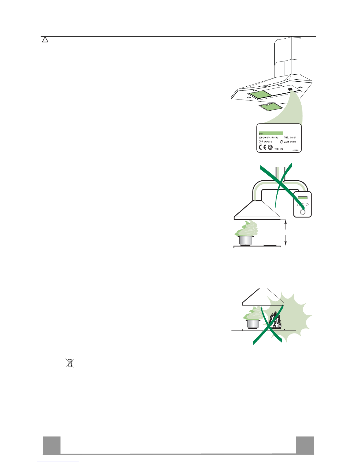
• The minimum safety distance between the cooker top and the extractor
hood is 650 mm.
• Check that the mains voltage corresponds to that indicated on the rating
plate fixed to the inside of the hood.
• For Class I appliances, che ck that the domestic power su pply guarantees
adequate earthing.
Connect the extr actor t o the exh aus t flue thr ough a pi pe o f mini mum di ame-
ter 120 mm. The route of the flue must be as short as possible.
• Do not connect the extractor hood to exhaust ducts carrying combustion
fumes (boilers, fireplaces, etc.).
• If the extractor is us ed i n c onjunction wit h no n- electrical appliances (e.g. gas
burning appl iances), a s ufficient degree of aeration mu st be guarant eed in
the room in orde r to preve nt the backflow of ex haust gas. The kit chen mus t
have an open ing com municating directly wi th the o pen air in order t o guarantee the entry of clean air.
USE
• The extractor hood has been designed exclusively for domestic use to eliminate kitchen smells.
• Never use the hood for purposes other than for which it has ben designed.
• Never lea ve high na ke d fla me s un de r the ho od wh en it i s in op er ati on .
• A djust th e flame intensity to direct it onto the bo ttom o f the pan only, m aki ng
sure that it does not engulf the sides.
• Deep fat fryers mus t be continuous ly monitored du ring use: over heated oil
can burst into flames.
• Do not flambè under the range hood; risk of fire
• This appliance is not intended for use by persons (incl uding children) with
reduced physi cal, sensory or m ental capabi lities, or lack o f experience an d
knowledge, unl ess th ey have been g iven su pervis ion o r instr ucti on con cern ing use of the appliance by a person responsible for their safety.
• Chi ldren should be s up ervised to ensur e that they do not pla y wi th t he appliance.
MAINTENANCE
• S wi tch of f or u nplug the appli an ce fr om the m ai ns s up pl y be fo re ca rr yi n g ou t
any maintenance work.
• Clean and/or replace the Filters after the specified time period.
• Clean the hood using a damp cloth and a neutral liquid detergent.
The symbol on the product or on its packaging indicates that this product may not be treated
as household waste. Instead it shall be handed over to the applicable collection point for the
recycling of elec tr i cal and el ectronic eq uipment. By ensuring this product is di s p osed of cor rectly,
you will help prevent potential negative consequences for the environment and human health,
which could otherwise be caused by inappropriate waste handling of this product. For more
detailed information about recycling of this product, please contact your local city office, your
household waste disposal service or the shop where you purchased the product.
650 mm min.
Page 8
EN
8
8
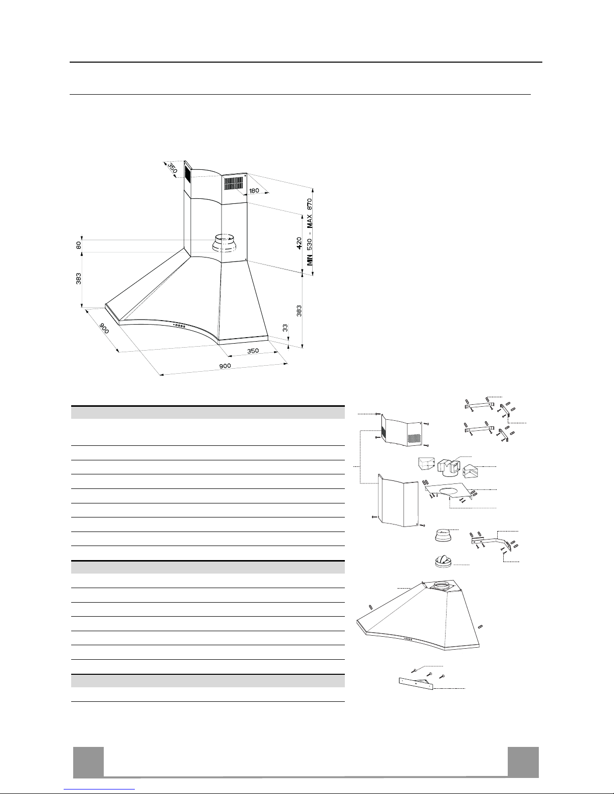
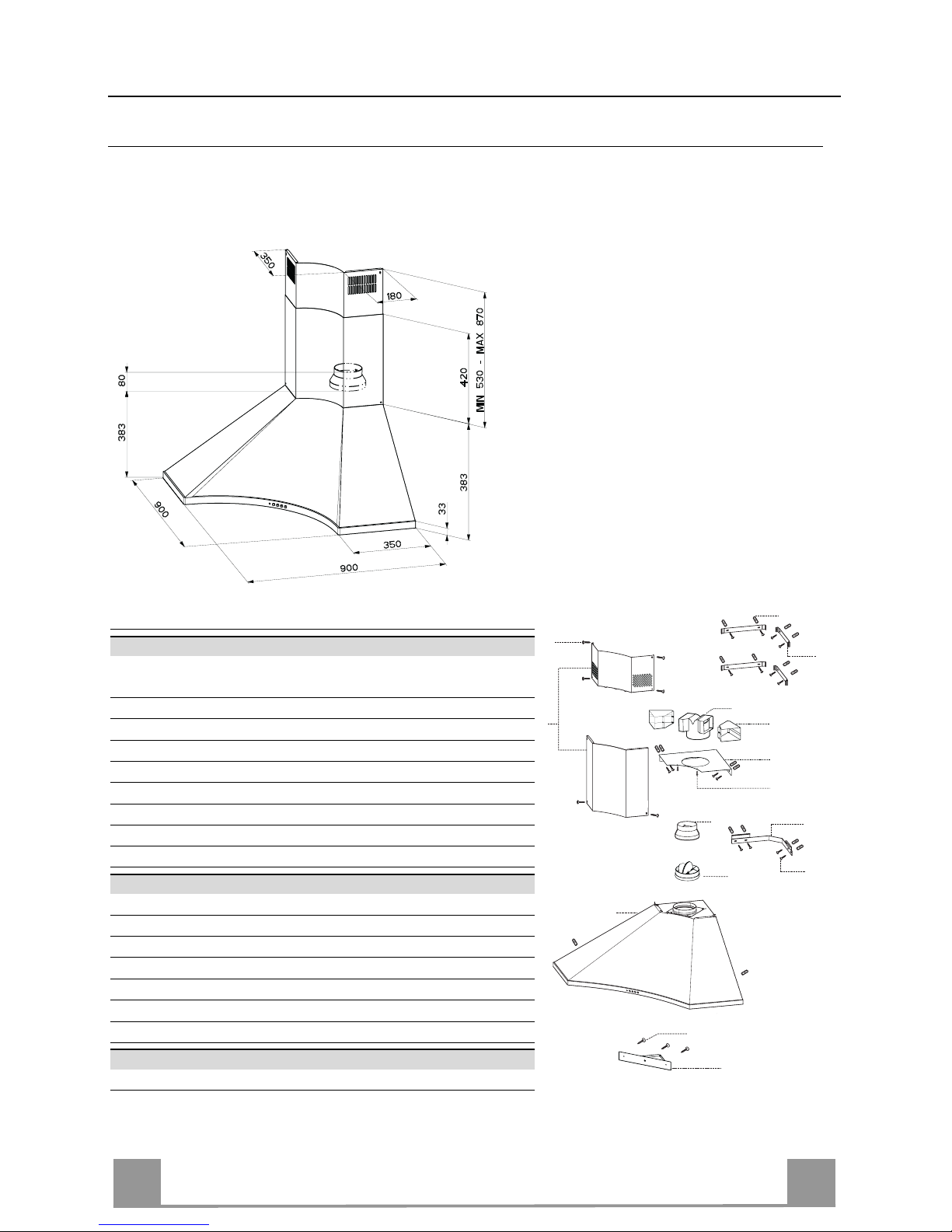
CHARACTERISTICS
Dimensions
Components
Ref. Q.ty Product Components
1 1 Hood Body, complete with: Controls, Light, Blower,
Filters
2 1 Telescopic Chimney comprising:
2.1 1 Upper Section
2.2 1 Lower Section
9 1 Reducer Flange ø 150-120 mm
10 1 Damper ø 150
14.1 2 Air Outlet Connection Extens ion
15 1 Air Outlet Connection
30 1 Lower corner spacer
Ref. Q.ty Installation Components
7.1 1 Hood Body Fixing Br ack et
7.2.1 4 Upper Chimney Section Fixing Brackets
7.3 1 Air Outlet Connection Support
11 18 Wall Plugs
12a 18 Screws 4,2 x 44,4
12c 6 Screws 2,9 x 9,5
12e 6 Screws 2,9 x 9,5
Q.ty Documentation
1 Instruction Manual
7.2.1
2.1
2.2
12c
2
9
7.1
12a
11
7.3
12e
1
15
14.1
12e
10
30
Page 9
EN
9
9
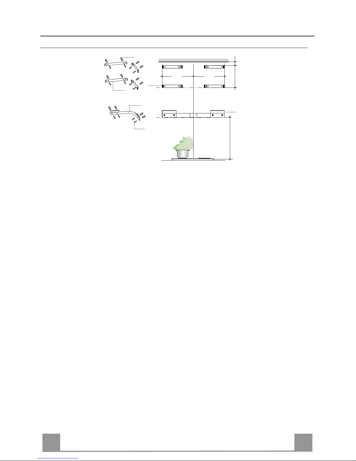
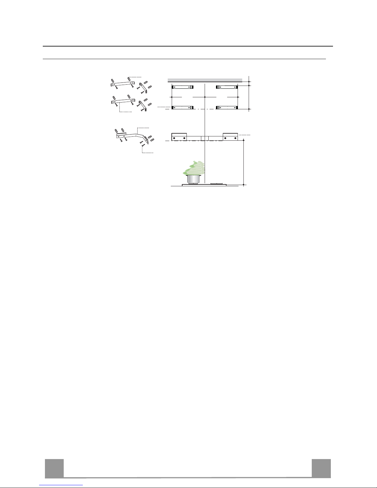
INSTALLATION
Wall drilling and bracket fixing
• Rest Bracket 7.1 as shown, 960 mm above the cooker top, taking care that the bracket is le-
vel.
• Mark the wall at the centr es of the holes in the bracket.
• Rest a Bracket 7.2.1 as shown, 1-2 mm from the ceiling or top limit, and 347 mm from the
corner of the wall.
• Mark the wall at the centr es of the holes in the bracket.
• Place bracket 7.2.1 on the wall as shown at X mm below the first bracket (X = height of the
upper
chimney section supplied), and 347 mm from the corner of the wall.
• Repeat this operation on the other side, checking that it is level.
• Drill ø 8 mm holes at all the centre points marked.
• Insert the wall plugs 11 in the holes.
• Fix the brackets and the Support using the 12a (4,2 x 44,4) screws supplied.
To install the hood in recycling version it is necessary to follow the instructions described
in the part concerning Recirculation version Air Outlet.
960
7.1
7.2.1
X
347 347
1÷2
7.1
12a
11
7.2.1
Page 10
EN
110
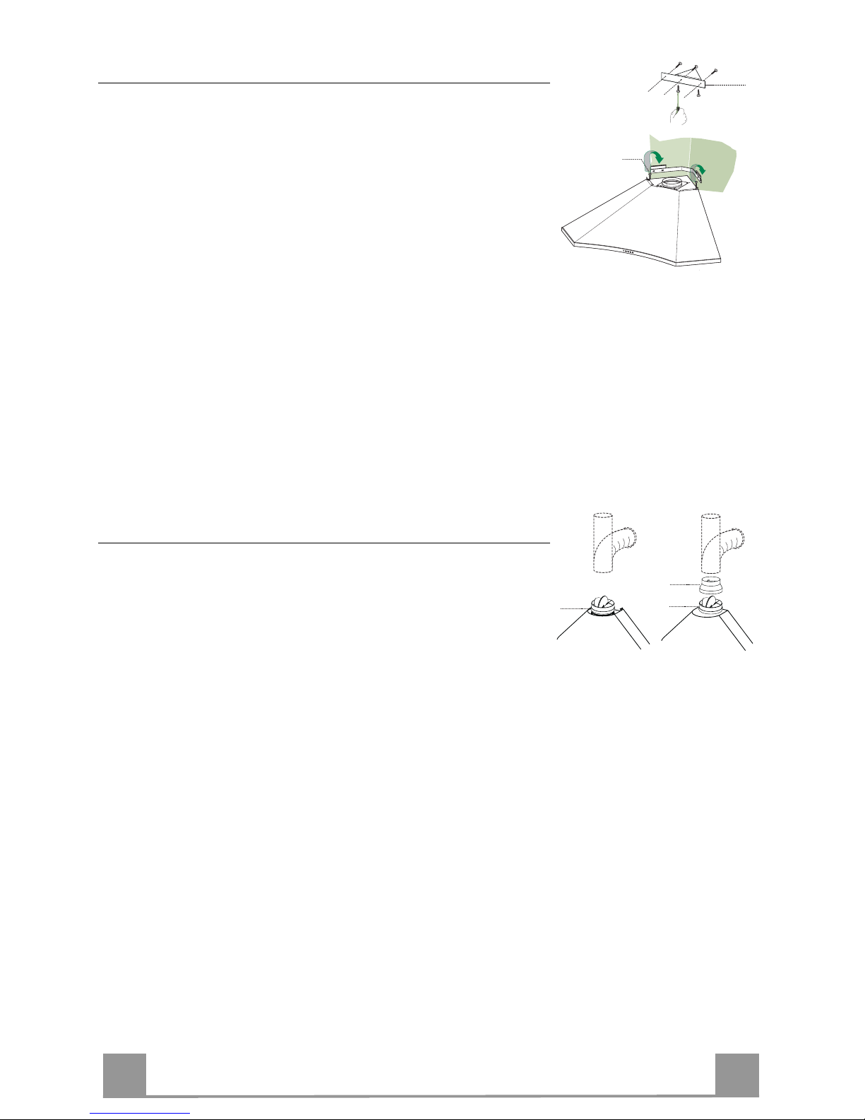
Fitting the Hood Canopy
Before fixing the Hood to the wall, Lower corner spacer 30 mus t
be connected t o t he Hood Canopy as follows:
• Loosen t he 2 Screws that jo in the elements making up a Lower
corner spacer 30.
• Fasten th e Lower corner sp acer 30 to the Hood using 3 Screws
(2.9 x 9.5) provided.
• Adjust the Screws Vr, located on the Hood Canopy connection
points, so that th ey are at th e half-way point.
• Hook the Hood Canopy to the Bracket provided.
• It is now possible to level the hood canopy, using the screws
Vr.
• Lock the 2 Screws in the Lower corner spacer, loosened as
above, after moving the mobile part until it is in the right position.
• If necessary, it is possible to fasten the hood to the wall using
two more screws with wall plugs, which can be positioned
from inside the hood canopy.
Vr
30
Connections
DUCTED VERSION AIR EXHAUST SYSTEM
When installing the ducted version, connect the hood to the
chimney using either a flexible or rigid pipe ø 150 or 120mm, the
choice of which is left to the installer.
To install a ø 150
• To install the dumper 10
• Fix the pipe in position using sufficient pipe clamps (not supplied).
To install a ø 120
• To install a ø 120 mm air exhaust connection, insert the reducer flange 9 on the dumper 10.
• Fix the pipe in position using sufficient pipe clamps (not supplied).
• Remove any activated charcoal filters.
ø 120
ø 150
9
10
10
Page 11
EN
111
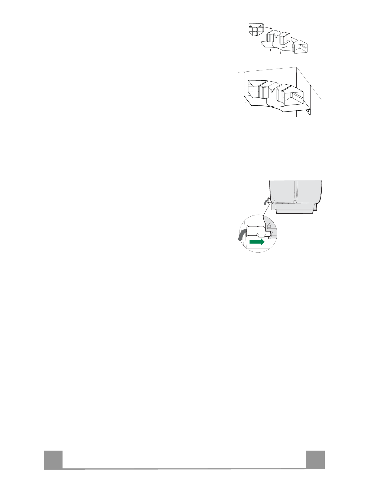
RECIRCULATION VERSION AIR OUTLET
• Insert the extension p ieces 14.1 laterally on the air outlet connection piece 15.
• Fix the connection piece with the extension pieces onto the
support 7.3 using the two screws 12e (2,9 x 9,5) provided.
• Place the assembled unit on the wall corner at 110 mm from
the ceiling or upper limit.
• Mark the centre of the bracket holes.
• Drill the marks ø 8 mm.
• Insert wall plugs 11 into the holes.
• Fix t he co n nect ion p iece u sin g the scre ws 12a (4,2 x 44,4) provided.
• Make sure that the charcoal filter has been mounted inside the
hood.
12e
110 mm
110 mm
ELECTRICAL CONNECTION
• Connect the hood to the mains through a two-pole switch having a contact gap of at least 3 mm.
• Remove the grease filters (see paragraph Maintenance) being
sure that the co nnector of the feeding cable is correctl y inserted
in the socket placed on the side of the fan.
Page 12
EN
112
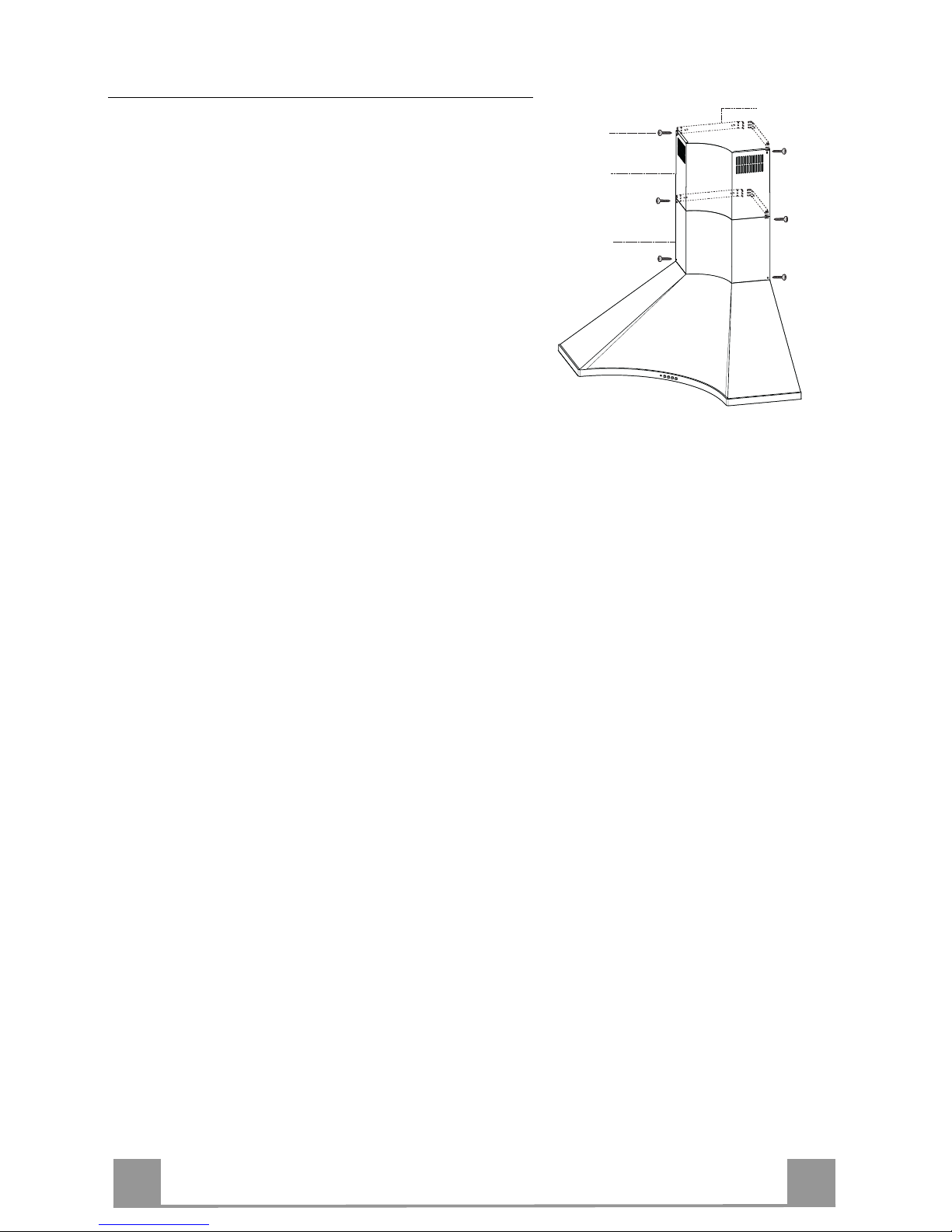
Chimney assembly
Upper exhaust Chimney
• Slightly widen the two sides of the upper chimney
and hook them behind the brackets 7.2.1, making
sure that they are well seated.
• Secure the sides to the brackets using the 4 screws
12c (2,9 x 9,5) supplied.
Lower exhaust Chimney
• Slightly widen the two sides of the chimney and hook
them between the upper chimney and the wall, making sure that they are well seated.
• Fix the lower part laterally to the hood body using
the 2 screws 12c (2,9 x 9,5) supplied.
7.2.1
2.1
12c
2.2
Page 13
EN
113
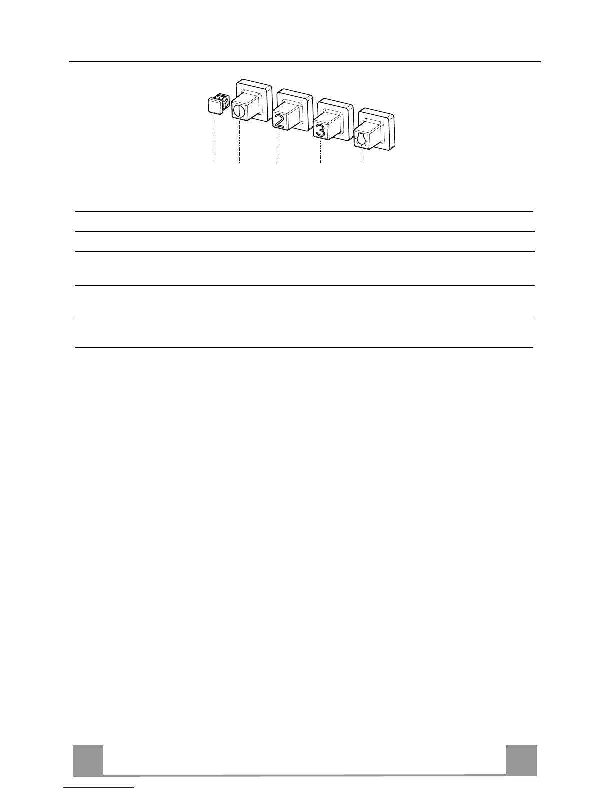
USE
S
V1V1V1V1V1V1V1V1V1V1V1V1V1V1V1V1V1V1
V2
V3
L
L Light Switches the lighting system on and off.
S Led Motor running led.
V1 Motor Switches the extractor motor on and off at low speed. Used to provide a
contin-uos and silent air change in the presence of light cooking vapours.
V2 Speed Medium speed, suitable for most operating conditions given the optimum
treated air flox/noise level ratio.
V3 Intensive Maximum speed, used for eliminating the highest cooking vap our emission,
including long periods.
Page 14
EN
114
MAINTENANCE
Grease filters
CLEANING METAL SELF- SUPPORTIN G GREASE FILTERS
• The filters must be cleaned every 2 months of operation, or
more frequently for particularly heavy usage, and can be
washed in a dishwasher.
• Remove the filters one at a time holding them up with one
hand and pulling the handle downwards with the other hand at
the same time.
• Wash the filters, taking care not to bend them. Allow them to
dry before refitting.
• When refitting the filters, make sure that the handle is visible
on the outside.
Activated charcoal filter (Recirculation version)
These filters are not washable and cannot be regenerated, and
must be replaced app roximately every 4 months of op eration, or
more frequently with heavy usage.
REPLACING THE ACTIVATED CHARCOAL FIL T ER
• Re move the metal grease filters
• Remove the saturated activated charcoal filter as shown (A).
• Fit the new filters (B).
• Replace the metal grease filters.
A
B
Lighting
LIGHT REPLACEMENT
20 W halogen light.
• Remove the snap-on lamp cover by levering it from under the
metal ring, supporting it with one hand.
• Remove the halogen lamp from the lamp holder by pulling
gently.
• Replace the lamp with a new one of the same type, making
sure that you insert the two pins properly into the housings on
the lamp holder.
• Replace the snap-on lamp cover.
Page 15
EN
115
EASY CLEANING TM
Removing the Grease Filters
Before carrying out Maintenance on the EASY CLEANING Suction Unit:
• Disconnect the hood by switching off the
twopole switch on the mains power supply
line, or by switching off the main power
switch.
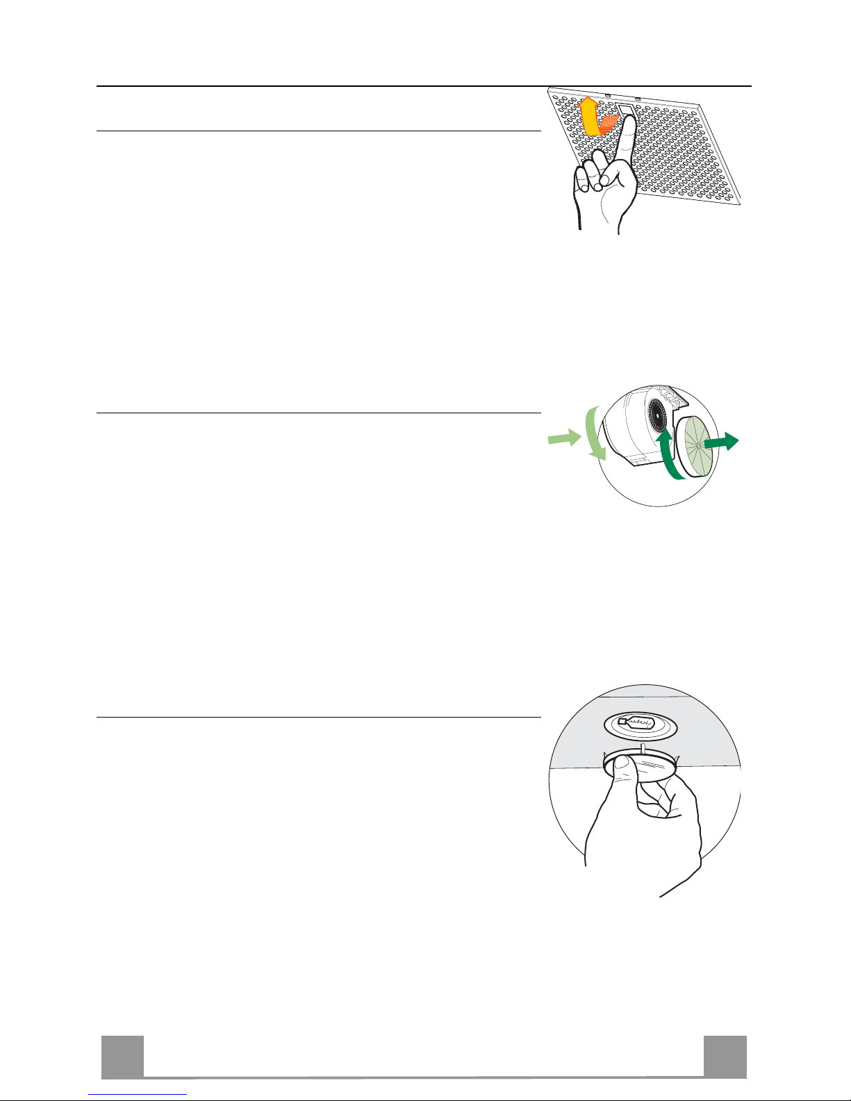
• Remove the grease filters from the hood.
• If the hood is of the recirculation type, remove the odour filters:
• For ho ods with a flat cartrid ge (A): turn the
fastening elemen ts provided;
• For hoods with a bayonet cartridge (B):
turn as indicated and extract.
Disconnecting the EASY CLEANING Suction Unit
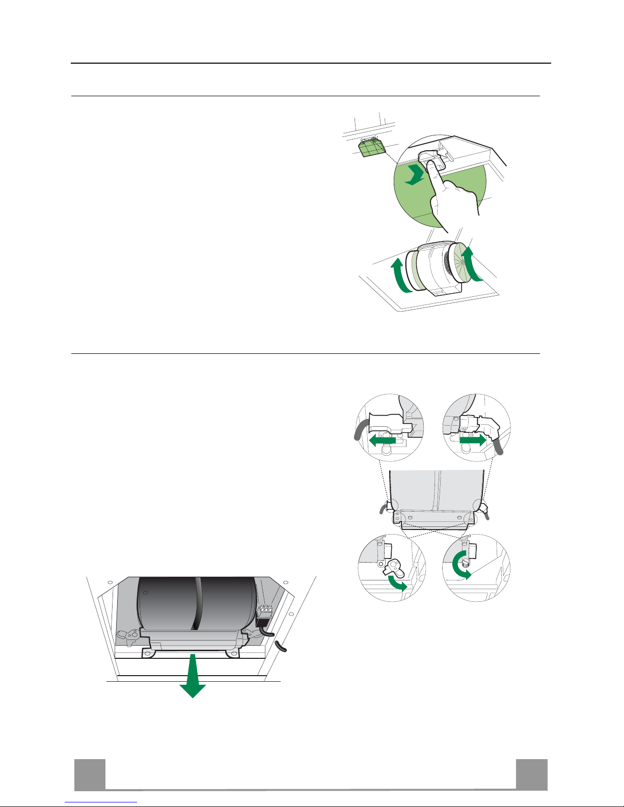
• Disco nn ect th e power con nect or Ca and the
control and lighting connector Cmd on the
sides of the unit.
• For wall-mounted hoods and free-standing
hoods with square chimney, turn the levers
Lb locking the suction unit, so that they
disconnect from the pins.
• For free-standing hoods with round chimney, unscrew the plugs Vb locki ng the su ction unit.
• Pull the suction unit forwards so that it unhooks from the support pins, and remove it
downwards through the air outlet.
CmdCa
Lb
Vb
A
B
Page 16
EN
116
Dismantling Washable Parts
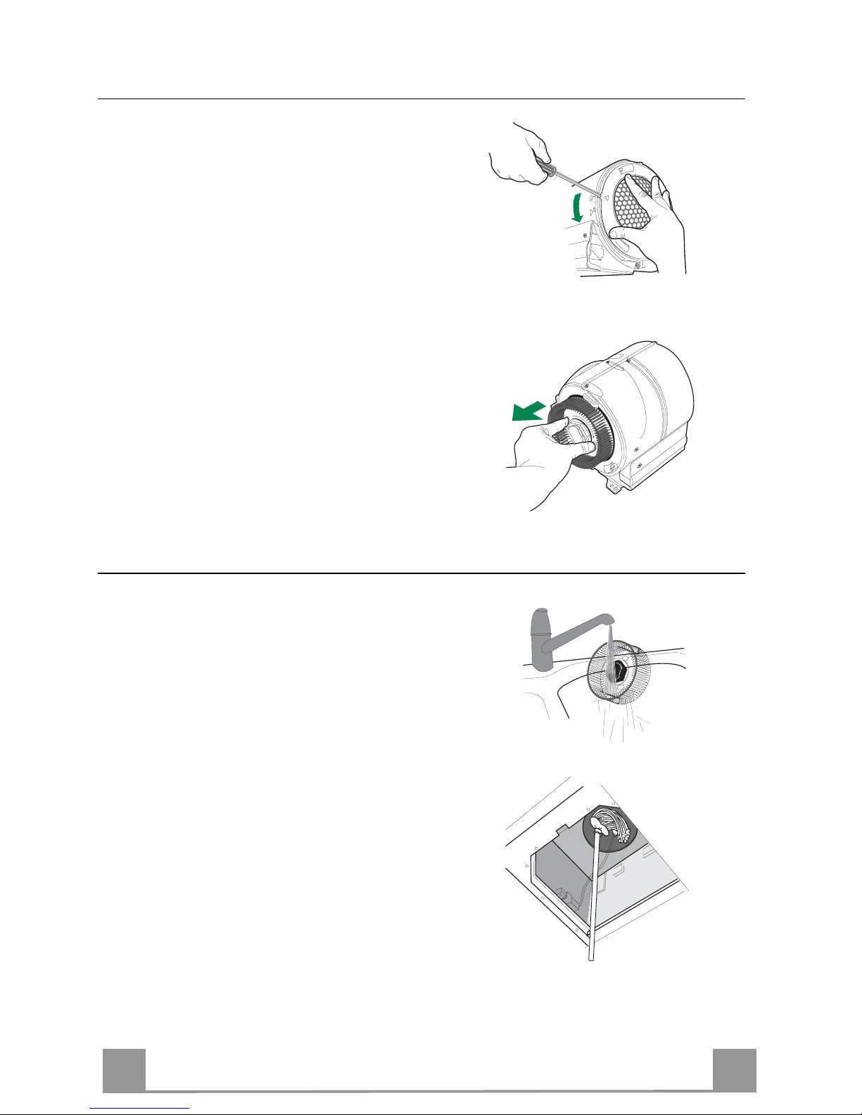
• To remove the side grilles protecting the
fans, lift up the stop tooth using a knife or
screwdriver and turn the grilles in the direction indicated by the arrow.
• Grasp the fans in the holes provided and
pull to extract .
CLEANING
• Wash the fans and the protection grilles,
using normal washing-up liquid. These
elements can also be washed in the dishwasher.
• Using a damp cloth and a suitable detergent, clean the body of the suction device,
taking great care not to allow any water to
leak into the inside of the unit or into the
connector housings.
• Leave until completely dry bifore reassembling.
• Using a brush, clean the air outlet pipe as
far as you can reach.
F
R
E
E
L
O
C
K
O
P
E
N
Page 17
EN
117
REASSEMBLY
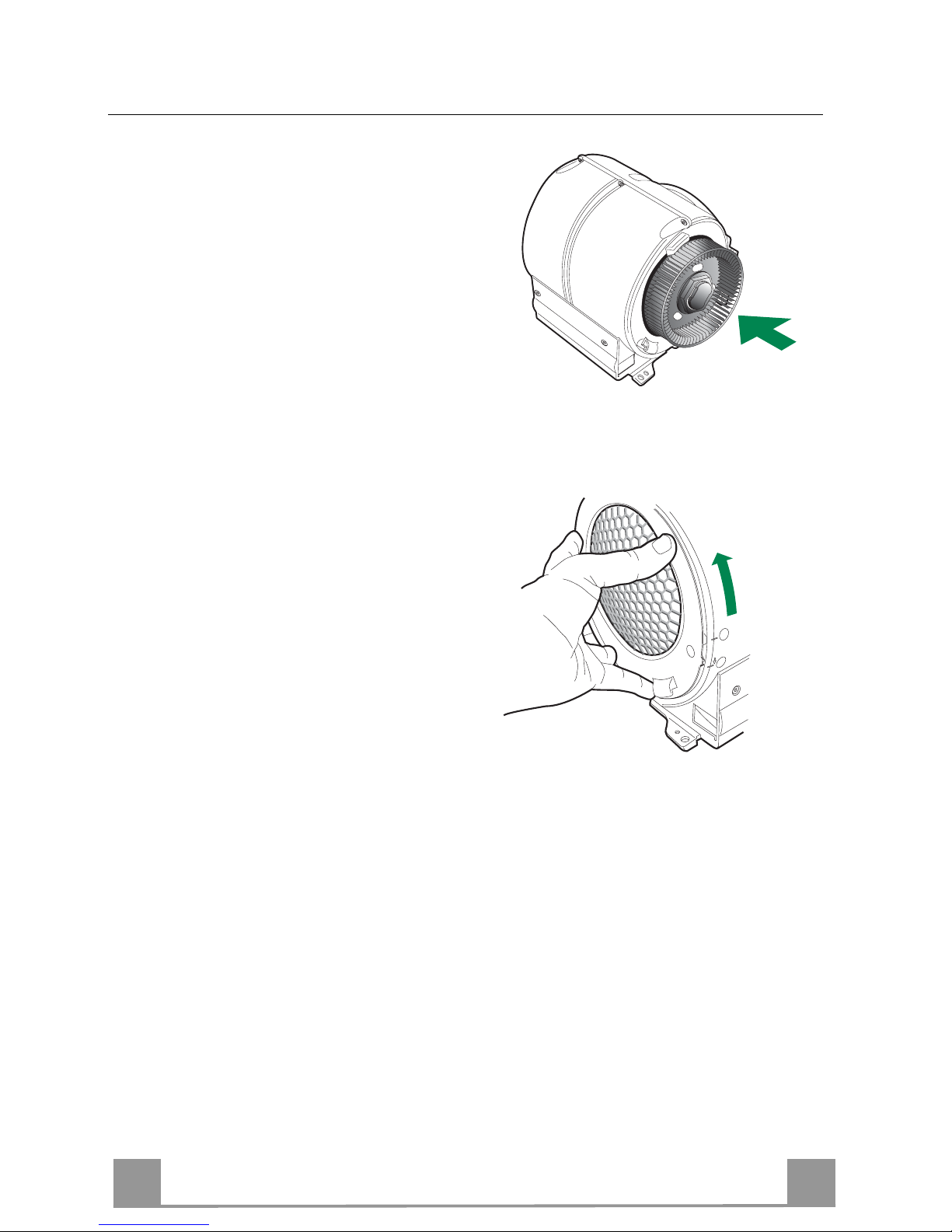
N.B. To avoid reassembling the wrong way
round, the two fans have different couplings.
• Reassemble the fans on the corresponding
pins, pressing them until they snap into
place.
• Fit the protection grilles so that the teeth
coincide in t he “FREE” position and when
turned to “LOCK”.
• Replace the EASY CLEANING suction
unit on the hood, inserting it in position and
connecting it to the support pins.
• Turn the lock levers, or screw in the lock
plugs.
• Connect the power connector and the
command connector to the sockets on the
sides of the suction device.
• Replace any activated charcoal odour filters.
• Replace the grease filters.
• Connect the hood to the power s upply system, by turning the two-pole switch on the
mains power line to on, or by turning the
main switch on.
• Check that the hood is working properly,
by turning the motor and lighting on.
LOCK
O
P
E
N
F
R
E
E
Page 18

DK
118
RÅD OG ANVISNINGER
Denne brugervejledning gælder for fl er e versioner af a pparatet.
Der fremstilles muligvis enkelte dele af tilbehøret, der ikke vedrører jeres apparat.
INSTALLATION
• Producenten kan ikke holdes ansvarlig for eventuelle skader, der skyldes ukorrekt
eller forkert installation.
• Den mindst tilladelige sikkerhedsafstand mellem komfurets top og emhættens underside er 650 mm.
• Kontrollér, at lysnetspændingen er den samme som den spænding, der er angivet
mærkepladen, der sidder på inde i emhætten.
• For Klasse I apparater skal det også kontrolleres, at elforsyningen er forsynet med
jord.
• Emhætten kobles til aftrækskanalen ved hjælp af et rør med en min.-diameter på
120 mm. Afstand en f r a emhætten til kanalen skal være så kort som mulig.
• Emhætten må ikke tilsluttes en kanal, der fører forbrændingsgasser ud i det fri (oliefyr, brændeovne etc.).
• Hvis emhætten skal anvendes i forbindelse med ikke-elektriske apparater (f.eks.
gaskomfur, gaskogeblus), skal det sikres, at lufttilgangen til rummet er tilstrækkelig,
så aftræksgasserne ikke slår tilbage. Køkkenet skal have en åbning, der har direkte
forbindelse til det fri, så der er sikret en tilstrækkelig mængde ren luft.
ANVENDELSE
• Emhætten er udelukkende beregnet til at fjerne em og lugte i køkkener i private
husholdninger.
• Emhætten må kun anvendes til det f ormål, hvortil den er konstrueret.
• Der må ikke forekomme høj åben ild under emhætten, mens den anvende s.
• Justér brænderen, så flammerne er rettet direkte mod bunden af panden/gryden –
de må ikke nå ud over kanten af bunden.
• Frituregryder skal under brug holdes under konstant opsyn: kogende varm olie kan
sprøjte ind i f lammerne.
• Emhætten må ikke anvendes af børn og personer, som ikke ved, hvordan den betjenes.
• Apparatet er ikke beregnet til at skulle anvendes af mindre børn eller svækkede
personer uden opsyn.
• Undlad at flambere r etter under em hæt ten; der opst år ellers brandfare.
• D ette appa rat må ikke anvendes af personer ( derunde r børn) med nedsatte psykiske, sensoriske eller sindsmæssige evner, eller personer uden erfaring eller tilstrækkeligt kendskab, med mindre de overvåges eller oplæres i brug af apparatet af
personer, der er ansvarlige for deres sikkerhed.
• Børn skal overvåge s for at undgå, at de leger med appar atet.
VEDLIGEHOLDELSE
• Inden apparatet skal vedligeholdes eller rengøres, skal der slukkes for det eller
stikket skal t ages ud af stikkont akt en.
• Rengør og/eller udskift filtrene iht. det angivne tidinterval.
• Rengør emhætten ved hjælp af en fugtig klud og et neutralt flydende rengøringsmiddel.
Symbolet på produktet eller på pakken angiver, at dette produkt ikke må behandles som husholdningsaffald. Det skal i stedet overgives til en affaldsstation for behandling af elektrisk og elektronisk udstyr. Ved at sørge for at dette produkt bliver bortskaffet på den rette måde, hjælper du med til
at forebygge eventuelle negative påvirkninger af miljøet og af personers helbred, der ellers kunne
forårsages af forkert bortskaffelse af dette produkt. Kontakt det lokale kommunekontor, affaldsselskab eller den forretning, hvor produkt er købt, for yderligere oplysninger om genanvendelse af dette
produkt.
650 mm min.
Page 19
DK
119
APPARATBESKRIVELSE
Dimensioner
Komponenter
Ref. Stk. Produktets komponenter
1 1 Emhættens hoveddel inkl.: Betjeningsanordninger, lys,
ventilatorenhed, filtre
2 1 Teleskopaftræk bestående af:
2.1 1 Nederste aftræk
2.2 1 Øverste aftræk
9 1 Passtykke ø 150-120 mm
10a 1 Sidestykke med ventil
14.1 2 Forlænger til l uftudstrømnings over gangsstykke
15 1 Luftudstrømnings overgangsstykke
30 1 Hjørnedæksel forneden
Ref. Stk. Installationsdele
7.1 1 Besla g til befæstigelse af emhættens hoveddel
7.2.1 4 Beslag til befæstigel se af øverste aftræk
7.3 1 Beslag til befæstigelse af filtrerende overgangsstykke
11 18 Forankringer ø 8
12a 18 Skruer 4,2 x 44,4
12c 6 Skruer 2,9 x 9,5
12e 6 Skruer 2,9 x 9,5
Stk. Dokumentation
1 Brugerhåndbog
7.2.1
2.1
2.2
12c
2
9
7.1
12a
11
7.3
12e
1
15
14.1
12e
10
30
Page 20
DK
220
INSTALLATION
Boring i væg og befæstigelse af beslag
• Placér beslaget 7.1 som vist, d.v.s. 960 mm over kogepladen, hvorved man skal passe på, at
beslaget er nivelleret.
• Afmærk midten af hullerne i beslaget.
• Placér beslaget 7.2.1 som vist, d.v.s. 1-2 mm fra loftet eller den øverste grænse og 347 mm
fra væggens hjørne.
• Afmærk midten af hullerne i beslaget.
• Placér beslaget 7.2.1 som vist, X mm under det første beslag (X=højden på det øverste af-
træk, der følger med) og 347 mm fra væggens hjørne.
• Gør det samme på den anden side, og kontrollér nivelleringen.
• Bor et hul med ø 8 mm på de afmærkede steder.
• Sæt forankringerne 11 i hullerne.
• Fastgør beslagene ved hjælp af de medfølgende skruer 12a (4,2 x 44,4 ).
Ved installation som filtrerende version skal man straks foretage proceduren, der er
fremstillet i afsnittet Luftudledning på Filtrerende Version
960
7.1
7.2.1
X
347 347
1÷2
7.1
12a
11
7.2.1
Page 21

DK
221
Montering af emhættens hoveddel
Før emhætten installeres på væggen, skal dækslet 30 sættes på
emhættens hoveddel på følgende måde:
• Lø sn de 2 skruer, der holder dæksl ets enkeltdele 30 sammen.
• Fastgør dækslet 30 på emhætten ved hjælp af de 3 medfølgen-
de skruer (2,9 x 9,5 ).
• Stil skruerne Vr på emhættens hoveddels fastgøringssteder
omtrent midt på deres vandring.
• Sæt emhættens hoveddel på det indrettede beslag.
• Nu er det muligt at nivellere emhættens hoveddel ved hjælp af
skruerne Vr.
• Stram dækslets 2 skruer, der tidligere blev løsnet, dog først når
man har fundet frem til den rigtige position ved at flytte på
dens bevægelige dele.
• Emhætten kan om nødvendigt fastgøres bedre til væggen ved
hjælp af to skruer mere med forankring, der kan anbringes inden i emhættens hoveddel.
Vr
30
Tilslutninger
VERSION FORBUNDET TIL AFTRÆKSKANAL
Når aftrækskanal-versionen opsættes, forbindes emhætteenheden
til kanalen med en flexslange eller et hårdt rør, Ø150 eller 120
mm – valget er op til den, der opsætter emhætten.
Tilslutning af rør på ø 150
• Indsæt studsen på ø 150 10 på emhættens udsugningshul.
• S pænd røret fast med specielle rørklemmer. Disse medleveres
ikke.
Tilslutning af rør på ø 120
• Ved tilslutning af rør på ø120 mm, indsættes reduktionsstudsen
9 på studsen ø 150, som er monteret tidligere.
• S pænd røret fast med specielle rørklemmer. Disse medleveres
ikke.
• I begge tilfælde skal man fjerne eventuelle lugtabsorberende
kulfiltre.
ø 120
ø 150
9
10
10
Page 22

DK
222
LUFTUDLEDNING PÅ FILTRERENDE VERSION
• Før overgangsstykkets forlængere 14.1 ind på siden af over-
gangsstykket 15.
• Skru overgangsstykket med forlængere fast til holderen 7.3 ved
hjælp af de 2 medfølgende skruer 12e (2,9 x 9,5).
• Sæt overgangsstykket og holderen på væggens hjørne, 110 mm
fra loftet eller den øverste grænse.
• Afmærk midten af hullerne i beslaget.
• Bor et hul med ø 8 mm på de afmærkede steder.
• Sæt forankringerne 11 i hullerne.
• Fastgør overgangsstykket ved hjælp af de medfølgende skruer
12a (4,2 x 44,4 ).
• Sørg for, at lugtfiltret med aktivt kul er monteret.
12e
110 mm
110 mm
TILSLUTNING TIL S TRØMFORSYNING
• Tilslut emhætten til elnettet, idet der indsættes en topolet afbryder med en kontaktafstand på mindst 3 mm.
• Fjern fedtfiltrene (se afsnittet ”Vedligeholdelse”) og kontroller,
at eltilslutningens kabelklemme er korrekt indsat i udsugningsgruppens stik.
Page 23

DK
223
Montering af aftræk
Øverste del af aftrækskanalen
• Udvid let de to sider på den øverste aftrækskanalen
og hægt dem bag ved bøjlerne 7.2.1, idet der sørges
for, at de sidder godt.
• Fastgør de to sider til bøjlerne ved hjælp af de 4
skruer 12c (2,9 x 9,5), der følger med.
Sænk aftrækskanalen
• Udvid let de to sider på aftrækket og hægt dem mellem det øverste aftræk og væggen, idet der skal sørges for, at de sidder godt.
• Fastgør den nederste del lateralt til emhætten ved
hjælp af de 2 skruer 12c (2,9 x 9,5), der medfølger.
7.2.1
2.1
12c
2.2
Page 24

DK
224
BRUG
S
V1V1V1V1V1V1V1V1V1V1V1V1V1V1V1V1V1V1
V2
V3
L
L Lys Tænder og slukker for lyssystemet.
S Lysdiode Motorfungerende lysdiode.
VI Motor Tænder og slukker udsugningsmotoren på lav hastighed. Bruges til at give
en constant og lydløs luftudskiftning, hvis der er lette madlavningsdampe.
V2 Hastighed Middelhastighed, passende til de fleste driftbetingelser forudsat optimalt
forhold mellem behandlet luft/støjniveau.
V3 Intensiv Højeste hastighed, bruges til at fjerne de madlavningsdampe, der udsendes
på højeste varme, inklusive lange perioder.
Page 25

DK
225
VEDLIGEHOLDELSE
Fedtfiltre
RENGØRING AF SELVBÆR ENDE FEDTFILTRE AF METAL
• De kan også vaskes i opvaskema skine, og de skal ren ses cirka
hver 2. måned ved almindelig anvendelse, helst oftere ved intensiv anvendelse.
• Fjern filtrene, ét ad gangen, og hold dem fast med den ene
hånd, mens grebet trækkes nedad med den anden.
• Skyl filtrene uden at bøje dem, og lad dem tørre, før de sættes
på plads igen.
• Sæt dem på plads igen, og sørg for, at håndtaget vender mod
den synlige yderside.
Hajusuodatin (Suodatinversio)
Suodattimia ei voi pestä eikä uudistaa, vaan ne täytyy vaihtaa
vähintään neljän kuukauden välein tai useammin, mikäli laitetta
käytetään pal jon
AKTIIVIHIILISUODATTIMEN VAIHTAM
• Irrota metalliset rasvasuodattimet.
• Irrota vanhat aktiivihiilisuodattimet kuten kuvassa (A).
• Asenna uudet suodattimet paikalleen kuten kuvassa (B).
• Laita metalliset rasvasuodattimet paikoilleen.
A
B
Lys
UDSKIFTNING AF LYS
20 W halogenlys.
• Tag lampedækslet med snaplås af ved at løfte det fra neden
under metalringen, idet du støtter med en hånd.
• Tag halogenlampen af lampeholderen ved at trække forsigtigt.
• Udskift lampen med en ny af samme type, idet du sørger for, at
du isætter de to tappe korrekt i hylstrene på lampeholderen.
• Sæt lampedækslet med snaplås tilbage på plads.
Page 26

DK
226
EASY CLEANING TM
Udtagning af fedtfiltre
Før man går i gang med vedligeholdelsen af
EASY CLEANING udsugningsenheden:
• Frakobl emhætten ved at aktivere den topolede afbryder, der er installeret på netforsyningen, eller hoved afbr yderen .
• Fjern fedtfiltrene fra emhætten.
• Fjern lugtfiltrene, hvis det drejer sig om
den filtrerende version af emhætten:
• Hvis emhætten er forsynet med flad indsats
(A): Indvirk på de dertil beregnede hager;
• Hvis emhætten er forsynet med bajonetindsats (B): Drej som vist på billedet, og tag
den ud.
Frakobling af EASY CLEANING udsugningsenheden
• Frakobl forsyningskonnektoren Ca og betjeningsanordningernes og belysningens
konnektor Cmd på enhedens sider.
• På vægmonterede emhætter og emhætter
over kogeøer med rektangul ært aftræk, s kal
udsugningsenhedens spærregreb Lb drejes
og frakobles tappene.
• På emhætter over kogeøer med rundt aftræk, skal udsugningsenhedens spærhager
Vb løsnes.
• Træk udsugningsenheden frem, så den frakobles støttetappene, og tag den ud via
luftudgangen, i nedadgående retning.
B
A
CmdCa
Lb
Vb
Page 27

DK
227
Afmontering af de dele, der kan vaskes
• Sideristene, der beskytter rotorerne, fjernes
ved at hæve spærrehakkene med spidsen af
en skruetrækker eller en kniv og dreje d em
i pilens retning.
• Tag fat i rotorerne i hullerne, og træk dem
ud.
RENGØRING
• Vask rotorerne og beskyttelsesristene med
et almindeligt opvaskemiddel. De kan også
vaskes i opvaskemaski ne.
• Rens udsugningsanordningens hoveddel
med en fugtig klud og et egnet rengøringsmiddel; pas på, at der ikke trænger vand ind
i enheden og konnektorernes sæder.
• Lad den tørre godt, før den sættes på plads
igen.
• Rens luftudgangsrøret så langt ind som muligt med en gulvskrubbe.
F
R
E
E
L
O
C
K
O
P
E
N
Page 28

DK
228
GENMONTERING
OBS: For at undgå at bytte om på rotorerne,
når de sættes på plads igen, er deres tilkoblingssteder forskellige.
• Sæt rotorerne tilbage på de tilsvarende tappe, idet der presses, indtil der høres et klik.
• Montér beskyttelsesristene, idet hakkene i
positionen ”FREE” skal befinde sig ud for
hinanden, og drej dem over mod ”LOCK”.
• Sæt EASY CLEANING udsugningsenheden på emhætten igen ved at placere den og
koble den fast til støttetappene.
• Drej spærregrebene eller stram spærhagerne.
• Forbind forsyningens og betjeningsanordningernes konnektorer med tilkoblingsstederne på siderne af udsugningsanordningen.
• Sæt lugtfiltret med aktivt kul på igen, såfremt det fo refindes.
• Sæt fedtfiltrene på igen.
• Tilkobl emhætten netforsyningen ved at
aktivere den topolede afbryder, der er installeret på netforsyningen, eller hovedafbryderen.
• Kontrollér funktionen ved at tænde for motoren og lysene .
LOCK
O
P
E
N
F
R
E
E
Page 29

SE
229
REKOMMENDATIONER OCH TIPS
Denna bruksanvisning är förutsedd för flera versioner av apparaten. Det är möjligt att
vissa enski l da utrustnings detaljer, int e berör din appar at .
INSTALLATION
• Tillverkaren å tar sig in get a nsva r för fe l som bero r på fe lak tig eller o läm plig in stallation.
• Avståndet mellan spisplattans ovansida och fläkt måste vara minst 65 cm. Om fläkten monteras över gasspis och högre monteringshöjd rekommenderas av gasspisens tillverkare ska hänsyn tas till detta.
• Kontrollera att matningsnätets spänning motsvarar den som anges på märkskylten
inuti fläkten.
• För klass 1 apparat er kontrollera att matningsnätet ger effektiv jordni ng.
• Anslut fläkten till frånluftskanalen via ett rör eller slang. Anslutningsslang måste
monteras sträckt närmast ansl utningen.
• Köks fläkten får inte ans lutas till frånluftska naler som leder fö rbränningsgaser (från
ved-/oljepa nnor, gas-/braskaminer etc. )
• Om fläkten används tills ammans med icke -elektriska sp isar (t.ex. gassp isar) måste
tillräcklig ven tilation garanteras i lokalen fö r att förhind ra backflöde av förbränn ingsgaser. Rummet måste ventileras tillräckligt när spisfläkten används.
• Avledning av utblåsningsluften skall utföras i enlighet med föreskrifter utfärdade av
berörd myndighet (Boverket ).
ANVÄNDNING
• Spisfläkten är uteslutande avsedd för hemmabruk och endast för att eliminera matos.
• Använd aldrig köksf läkten för andra ändamål än det avsedda.
• Undvik öppen (gas-)låga under spisfläkten när fläkten är i drift.
• Justera gaslågan så att flammorna endast berör kokkärlets undersida och inte
tränger upp längs dess sidor.
• Fritöser måste öv ervakas noggrant under användning: Överhett ad olja kan fatt a eld.
• Att flambera under fläkten är inte tillåtet, då det finns risk för eldsvåda
• Denna apparat får inte användas av personer (inklusive barn) med nedsatta fysiska,
sensoriska eller mentala förmågor, eller av personer utan erfarenhet och kunskap,
om inte de är övervakade eller instruerade om användningen av apparaten av personer ansvari ga för deras säkerhet.
• Barn ska övervakas för att säkerst älla att de inte leker med apparat en..
UNDERHÅLL
• Stäng av apparaten eller skilj den från elnätet innan något underhållningsarbete
utförs.
• Rengör och/eller byt filtren med angivet interval l.
• Rengör köksfläkten med en fuktig tr asa och diskmedel.
• Risken för brandspridning ökar om fläkten inte rengörs så ofta som anges i instruktionen.
Symbolen på produkten eller emballaget anger att produkten inte får hanteras som
hushållsavfall. Den skall istället lämnas in på uppsamlingsplats för återvinning av el- och
elektronikkomponenter. Genom att säkerställa att produkten hanteras på rätt sätt b idrar du till
att förebygga eventuella negativa miljö- och hälsoeffekter som kan uppstå om produkten
kasseras som vanligt avfall. För ytterligare upplysningar om återvinning bör du kontakta lokala myndigheter eller sophämtningstjänst, alternativt affären där du köpte varan.
650 mm min.
Page 30

SE
330
EGENSKAPER
Mått
Komponenter
Ref. Antal Produktkomponenter
1 1 Kupa komplett med: Reglage, belysning, fläktenhet,
filter
2 1 Teleskopisk skorsten, bestående av:
2.1 1 Undre skorsten
2.2 1 Övre skorsten
9 1 Reduceringss t os ø 150- 1 20 mm
10 1 Tättslutande spjäll
14.1 2 Anslutningsstycke för luftutsläpp
15 1 Luftstyrning
30 1 Konsol
Ref. Antal Installationskomponenter
7.1 1 Konsol för fastsättning av kupa
7.2.1 4 Konsol för fastsättning övre skorsten
7.3 1 Konsol för fastsättning av fi ltrerande anslutning
11 18 Expansionspluggar ø 8
12a 18 Skruvar 4,2 x 44, 4
12c 6 Skruvar 2,9 x 9,5
12e 6 Skruvar 2,9 x 9,5
Antal Dokumentation
1 Bruksanvisning
7.2.1
2.1
2.2
12c
2
9
7.1
12a
11
7.3
12e
1
15
14.1
12e
10
30
Page 31

SE
331
INSTALLATION
Borrning i vägg och fastsättning av konsoler
• Placera konsolen 7.1 960 mm ovanför tillagningshällen, se till att konsolen sitter vågrätt.
• Märk ut konsolens hål.
• Placera en konsol 7.2.1 1-2 mm från taket eller den övre gränsen, och 347 mm från väggens
hörn.
• Märk ut konsolens hål.
• Placera en kon sol 7.2.1 X mm under den första (X = höjd av den medföljande övre skorstenen), och 347 mm från väggens hörn.
• Märk ut konsolens hål.
• Borra ø 8 mm hål i de markerade punkterna.
• Sätt i expansionspluggarna 11 i hålen.
• Skruva fast konsolerna med de medföljande skruvarna 12a (4,2 x 44,4).
För install ation so m kolfilterfl äkt, utför momenten be skrivna i avs nittet Luf tutsläpp vi d
användning som kolfilterfl äkt.
960
7.1
7.2.1
X
347 347
1÷2
7.1
12a
11
7.2.1
Page 32

SE
332
Montering av kupa
Om installatören vill fylla tomrummet mellan nedre delen av
fläkten och hörnet, måste konsol 30 hakas fast i kupan innan kupan monteras på väggen.
• Lossa de 2 skruvarna som håller samman delarna av konsolen
30.
• Haka fast konsolen 30 i kupan med de medföljande 3 skruvar-
na (2,9 x 9,5).
• Skruva i skruvarna Vr som sitter i kupans fasthakningspunkter
halvvägs.
• Haka fast kupan på den förbredda konsolen.
• Justera kupan vågrätt med skruvarna Vr.
• Dra åt konsolens (30) 2 skruvar, som tidigare lossats, efter att
ha hittat det rätta läget genom att flytta dess rörliga del.
• Om du vill kan du fästa kupan på väggen med ytterligare två
skruvar och expan sionspluggar, som kan p laceras från insidan
av kupan.
Vr
30
Anslutningar
ANSLUTNING TILL FRÅNLUFTSKANAL
• Spisfläkten är utrustad med 150 mm anslutning. 150 mm
slangsats finns som tillbehör. Om anslutningen ska ändras till
125 eller 160 mm finns övergångsstosar som tillbehör.
• Fixera slangen med hjälp av lämplig rörklammer. (medföljer
ej).
• Vid montering med anslutningsslang måste slangen monteras
sträckt närmast anslut ningen.
• Avlägsna eventuella kolfilter.
ø 120
ø 150
9
10
10
Page 33

SE
333
LUFTUTSLÄPP VID ANVÄNDNING SOM KOLFILTERFLÄKT
• Sätt i luftanslutningarna 14.1 på sidorna av luftstyrning 15.
• Skruva fast luftstyrningen med luftanslutningar på konsolen
7.3 med 2 medföljande skruvar 12e (2,9 x 9,5).
• Placera den monterade konsolen på väggens hörn på ett avstånd på 110 mm från taket eller den övre gränsen.
• Märk ut konsolens hål.
• Borra ø 8 mm hål i de markerade punkterna.
• Sätt i expansionspluggarna 11 i hålen.
• Skruva fast konsolen med de medföljande skruvarna 12a (4,2 x
44,4).
• Kontrollera att kolfilter är monterat.
12e
110 mm
110 mm
ELEKTRISK INSTALLATION
• Spisfläkten levereras med sladd och jordad stickpropp för anslutning till jordat uttag. Vägguttaget måste vara åtkomligt efter installation. Annan typ av anslutning eller utbyte av sladdställ ska utföras av behörig fackman.
• Avlägsna fettfiltren, (se avsnitt ”Underhåll”) och se till att elkontakten är korrekt anslutet i uttaget på sidan av fläkten.
Page 34

SE
334
Montering av skorsten
Övre skorsten
• För försiktigt de två motstående sidorna av den övre
skorstensdelen utåt och haka dem bakom fästena
7.2.1. Se till att de sitter ordentligt.
• Fäst sidorna med de 4 skruvarna 12c (2,9 x 9,5).
Nedre skorsten
• För försiktigt de två motstående sidorna av den nedre
skorstensdelen utåt och haka fast dem mellan den
övre skorstensdelen och väggen. Se till att de kommer ordentligt på plats.
• Fäst den undre skorstensdelens sidor mot fläkthuset
med hjälp av de 2 skruvarna 12c (2,9 x 9,5)
7.2.1
2.1
12c
2.2
Page 35

SE
335
ANVÄNDING
S
V1V1V1V1V1V1V1V1V1V1V1V1V1V1V1V1V1V1
V2
V3
L
L - BELYSNING Tänder och släcker belysningen.
S - INDIKERINGSLAMPA Indikerar när motorn är i drift.
V1 - STRÖMBRYTARE Startar motorn på låg hastighet / stänger av motorn.
V2 - FLÄKTHASTIGHET Startar mellanhastigheten.
V3 - INTENSIVLÄGE Ökar till hög hastighet från tidigare vald hastighet.
Denna funktion är lämplig vid matlagning där intensivt
matos uppstår.
Page 36

SE
336
UNDERHÅLL
Rengöring av fettfilter
• Dessa kan även diskas i diskmaskin, de ska diskas varannan
månad cirka eller oftare vid intensiv användning.
• Ta bort ett filter åt gången, genom att stödja dem med den ena
handen och dra spaken nedåt med den andra handen.
• Diska filtren utan att böja dem. Låt filtren torka före återmonteringen.
• Montera filtren på nytt. Se till att handtaget vänder mot den
synliga utsidan
Kolfilter (filtrerande version)
Filtret kan inte diskas eller återanvändas. Det ska bytas ut var 4:e
månad eller oftare vid en mer intensiv användning.
BYTE AV KOLFILTER
• Ta bort fettfiltren av metall.
• Avlägsna de mättade kolfiltren, som visas (A).
• Montera de nya kolfiltren, som visas (B).
• Återmontera fettfiltren av metall.
A
B
Belysning
BYTE AV LAMPA
Halogenlampa 12V, 20W, sockel G4
• Lampglaset lossas genom att dra metallringen rakt ned.
• Dra ut halogenlampan ur lamphållaren
• Byt ut lampan mot en ny med samma egenskaper. Sätt in de
två piggarna korrekt i lamphållaren.
• Återmontera metallsockeln.
Page 37

SE
337
EASY CLEANING TM
Fläkten är försedd med Easy Clean motorpaket.
Risken för brandspridning ökar om spisfläkten inte rengörs så ofta som anges.
OBS! Motorpaketet får ej diskas eller utsättas för väta!
BORTTAGNING AV FETTFILTER
Fläkthjul, sidogaller samt insidan av fläkten ska rengöras
minst två gånger per år.
Innan du påbörjar underhållet av motorpaketet:
• Bryt strömmen
• Lossa fettfiltren.
• Ta därefter bort eventuellt kolfilter:
För spisfläktar med plan kassett (A), använd de speciella hakarna.
För spisfläktar med bajonettkassetter (B), vrid och dra ut, se bild.
DEMONTERING AV EASY CLEANING
• Motorpaketet demonteras gen om att elkontaktern a Ca
och Cmd på båda sidor om motorenheten först lossas.
• Vrid på spärrhakarna, (Lb för vägghängd/Vb för frihängd) som låser fast motorpaketet.
• På köksfläktarna med ö och rund skorstenssektion,
skruva loss spärrhakarna Vb på motorenheten.
• Dra enheten utåt, så att den lossnar från stiften, och
sedan nedåt.
A
B
Page 38

SE
338
Demontering av diskbara delar
• Sidogallren lossas genom att lyfta upp
stoppklacken med en skruvmejsel och vrida
gallret i pilens riktning.
• Fläkthjulen lossas genom att plasttapparna i
hjulens centrum pressas ihop samtidigt som
hjulen dras utåt.
RENGÖRING
• Filter, fläkthjul och sidogaller diskas i
diskmaskin. Delarna kan alternativt blötläggas i varmt vatten och diskmedel.
• Övriga delar av fläktens ut- och insida torkas med fuktig trasa och diskmedel.
• Använd inte blöta trasor eller svampar, inte
heller direkta vattenstrålar eller slipande
ämnen.
• OBS! Skydda motor och kontaktdelar från
väta.
F
R
E
E
L
O
C
K
O
P
E
N
Page 39

SE
339
ÅTERMONTERING
• För att undvika felaktig återmontering, har
fläkthjulen olika infä stning a r.
• Montera fläkthjulen på de motsvarande stiften och tryck tills ett klick hörs för fasthakningen.
• Montera skyddsgallren med låständerna
inpassade i läge “FREE”, vrid sedan mot
“LOCK”.
• Montera tillbaka EASY C LEANING. Kontrollera att delarna snäpper fast och att elkontakt och motorpaket sitter fast ordentligt.
• Återmontera fettfiltren efter rengöring, se
till att de snäpper fast ordentligt.
• Kontrollera funktionen genom att starta
motorn och tända belysningen.
L
O
C
K
O
P
E
N
FRE
E
Page 40

NO
440
ANBEFALINGER OG FORSLAG
Denne bruksanvisningen gjelder for flere maskinutgaver. Det kan finnes be-
skrivelser av enkelt e deler som ikke gjelder din maskin.
INSTALLASJON
• Produsenten skal ikke kunne holdes ansvarlig for eventuelle skader som oppstår som følge av feil eller ufullstendig mont ering.
• Minimum si kkerhetsavstand mell om komfyrtoppen og vifteh etten er 650 mm.
• Kontroller at nettspenningen er i overensstemmelse med spenningen som er
angitt på m erkeplaten på innsid en av hetten.
• For utstyr i klasse I må det kontrolleres at strømforsyningen garanterer tilstrekkelig jording.
• Koble suge viften til avtrekkskanalen gjennom et rør med en minimumsdiameter på 120 mm. Trekkanalens rute må være så kort som mulig.
• Ikke koble viftehetten til avtrekkskanaler med forbrenningsgasser (kjeler,
ildsteder osv.).
• Hvis sugeviften brukes sammen med ikke-elektriske apparater (f.eks. gassapparater), må det sørges for tilstrekkelig lufting i rommet for å hindre tilbakestrømning av avgass. Kjøkkenet må ha en direkte åpning til fri luft for å garantere tilførsel av ren luft.
BRUK
• Viftehetten er utviklet utelukkende for hjemmebruk for å motvirke lukter på
kjøkkenet.
• Bruk aldri hetten til andre formål enn den er beregnet for.
• Tillat aldri høye, åpne flammer under hetten når den er i bruk.
• Juster flammestyrken slik at bare bunnen av gryten oms luttes, og i kke sidene.
• Frityrkokere må overvåkes kontinuerlig under bruk: overopphetet olje kan ta
fyr.
• Hetten må ikke brukes av barn eller personer som ikke har fått opplæring i
korrekt bruk.
• Utstyret er ikke beregnet for bruk av ung e barn eller sykelige persone r uten
tilsyn.
• Ikke flambér under kjøkkenviften pga. brannfaren.
• D ette appara tet må ikke bruke s av pe rsone r (inkl. ba rn) med redu serte psykiske evner og ferdigheter, eller av uerfarne personer uten kjennskap til apparatet, hvis de ikke er under o ppsyn eller opplæring av personer ansvarlige for deres sikkerhet.
• Barn må holdes under oppsyn for å garantere at de ikke leker med apparatet.
VEDLIKEHOLD
• Slå av ell er koble app aratet fra s trømnettet før det utføres vedlikeholdsarbeid.
• Rengjør og/eller sk rift ut filtrene etter angitt tid.
• Rengjør hetten med en fuktig klut og et nøyt ralt, flytend e rensemidd el.
Symbolet på produkt et eller på emb allasje n viser a t dette pr odukt et ikke m å behan dles
som hushol dni ngs avf all . Det sk al derim ot brin ges til et mot tak f or r esir kul eri ng av elek tri sk o g
elektronisk utstyr. Ved å sørge for korrekt avhending av apparatet, vil du bidra til å forebygge
de negative konsekvenser for miljø og helse som gal håndtering kan medføre. For nærmere
informasj on om resirkul ering av dette produktet, ven nligst kontak t kommunen, r enovasjons selskape t eller forretningen der du anskaffet det.
650 mm min.
Page 41

NO
441
EGENSKAPER
Dimensjoner
Deler
Ref. Antall Produktets deler
1 1 Kjøkkenviftens hoveddel komplett med: Kontroller, lys,
vifteenhet, filtre
2 1 Uttrekkbart røkrør ; består av:
2.1 1 Nederste røkrør
2.2 1 Øverste røkrør
9 1 Reduksjons fl ens med en di a met er på 150- 12 0 mm
10 1 Flens med v entil
14.1 2 Forlengelsesledning for luftutløps kopling
15 1 Luftutløpskopling
30 1 Nederste vinkelplugg
Ref. Antall Installasjonsdeler
7.1 1 Festekonsoll til kjøkkenviftens hoveddel
7.2.1 4 Festekonsoller til øverste r økrør
7.3 1 Festekonsoller til filt reringskopli ng
11 18 Ekspansjonsplugger me d en diameter på 8 mm
12a 18 Skruer 4,2 x 44,4
12c 6 Skruer 2,9 x 9,5
12e 6 Skruer 2,9 x 9,5
Antall Dokumentasjon
1 Bruksveiledning
7.2.1
2.1
2.2
12c
2
9
7.1
12a
11
7.3
12e
1
15
14.1
12e
10
30
Page 42

NO
442
INSTALLASJON
Boring av hull i veggen og festing av konsollene
• Støtt konsollen 7.1 som vist 960 mm over platetoppen, og pass på at konsollen nivelleres.
• Merk av midten til hullene til konsollen.
• St øtt e n kon so ll 7.2.1 som vist 1-2 mm fra taket eller den øverste grensen, og 347 mm ut fra
vegghjørnet.
• Merk av midten til hullene til konsollen.
• Støtt en konsoll 7.2.1 som vist X mm under den første konsollen (X = høyden på det øverste
røkrøret som følger med), og 347 mm ut fra vegghjørnet.
• Gjenta dette arbeidet på motsatt side. Kontroller nivelleringen.
• Bor hull med en diameter på 8 mm i de avmerkede punktene.
• Sett ekspansjonspluggene 11 inn i hullene.
• Fest konsollene med skruene 12a (4,2 x 44,4) som følger med.
For installasjon i filtreringsversjon må arbeidet beskrevet i avsnittet Luftutløp for
filtreringsversjon utføres først.
960
7.1
7.2.1
X
347 347
1÷2
7.1
12a
11
7.2.1
Page 43

NO
443
Montering av kjøkkenviftens hoveddel
Før kjøkkenviften installeres på veggen må pluggen 30 festes til
kjøkkenviftens hoveddel på følgende måte:
• Løsne de to skruene som holder pluggens 30 deler sammen.
• Fest pluggen 30 til kjøkkenviften med de tre skruene (2,9 x
9,5) som følger med.
• Skru skruene Vr halvveis inn i festepunktene på kjøkkenvifte-
ns hoveddel.
• Fest kjøkkenviftens hoveddel til konsollen.
• Niveller nå kjøkkenviftens hoveddel med skruene Vr.
• Beveg pluggens bevegelige del slik at pluggen plasseres riktig,
og stram deretter til de to skruene.
• Kjøkkenviften kan festes til veggen med to ekspansjonsplugger
fra innsiden av kjøkkenviftens hoveddel.
Vr
30
Tilkoplinger
LUFTUTLØP FOR SUGEVERSJON
For installasjon av kjøkkenviften i sugeversjon må du kople
kjøkkenviften til utløpsrøret med et rør eller en slange med en
diameter på 150 eller 120 mm (etter eget valg).
Tilkopling av rør med en diameter på 150 mm
• Før flensen med en diameter på 150 mm 10 inn på utløpet fra
kjøkkenviftens hoveddel.
• Fest røret med egnete slangeklemmer. Nødvendig materiale
følger ikke med.
Tilkopling av rør med en diameter på 120 mm
• For tilkopling av rør med en diameter på 120 mm må du føre
inn reduksjonsflensen 9 på flensen med en diameter på 150
mm som du allerede har montert.
• Fest røret med egnete slangeklemmer. Nødvendig materiale
følger ikke med.
• I begge tilfellene må du fjerne eventuelle aktive kullfiltre.
ø 120
ø 150
9
10
10
Page 44

NO
444
LUFTUTLØP FOR FILTRE RI NG SVER SJO N
• Før forlengelsesledningene for koplingen 14.1 inn på
koplingen 15 frå siden.
• Stram koplingen med forlengelsesledningene til støtten 7.3
med de to skruene 12e (2,9 x 9,5) som følger med.
• Støtt koplingsstøtten i vegghjørnet med en avstand på 110 mm
fra taket eller den øverste grensen.
• Merk av midten til hullene til konsollen.
• Bor hull med en diameter på 8 mm i de avmerkede punktene.
• Sett ekspansjonspluggene 11 inn i hullene.
• Fest koplingen med skruene 12a (4,2 x 44,4) som følger med.
• Kontroller at det aktive kullfilteret er montert.
12e
110 mm
110 mm
ELEKTRISK TILKOPLING
• Kople kjøkkenviften til strømnettet med en topolet bryter med
en kontaktåpning på minst 3 mm.
• Fjern fettfiltrene (se avsnittet Vedlikehold) og kontroller at koplingsstykket til nettkabelen er korrekt innført i stikkontakten
til sugesystemet.
Page 45

NO
445
Montering av røkrøret
Øverste røkrør
• Utvid litt de to kantene på sidene og hekt dem på bak
konsollene 7.2.1. Lukk kantene deretter helt igjen.
• Fest kantene på sidene av konsollene med de fire
skruene 12c (2,9 x 9,5) som følger med.
Nederste røkrør
• Utvid litt de to kantene på sidene av røkrøret og hekt
dem på mellom det øverste røkrøret og veggen. Lukk
kantene deretter helt igjen.
• Fest den nederste siden til kjøkkenviftens hoveddel
fra siden med de to skruene 12c (2,9 x 9,5) som følger med.
7.2.1
2.1
12c
2.2
Page 46

NO
446
BRUK
S
V1V1V1V1V1V1V1V1V1V1V1V1V1V1V1V1V1V1
V2
V3
L
L Lys Tenner og slukker belysningen.
S Led Viser at motoren er slått på.
V1 Motor Tenner og slukker innsugningsmotoren ved min. hastighet. Denne hastigheten
er egnet til spesielt lydløs kontinuerlig luftsirkulasjon når det er lite matos.
V2 Hastighet Middels hastighet som er egnet til de fleste bruksforholdene. Forholdet luft-
strømning og lydnivå er ideelt.
V3 Hastighet Maks. hastighet som er egnet til forhold hvor det er mye matos også over leng-
re tid.
Page 47

NO
447
VEDLIKEHOLD
Fettfiltre
RENGJØRING AV DE SE LV BÆ RE ND E META LLI SK E FET TFI LT R EN E
• Filtrene kan vaskes også i oppvaskmaskinen. De må vaskes ca.
hver andre måned eller oftere avhengig av bruksforholdene.
• Fjern filtrene ett av gangen. Støtt dem med en hånd mens du
trekker spaken nedover med den andre hånden.
• Vask filtrene. Pass på at du ikke bøyer dem. La dem tørke før
du monterer dem igjen.
• Gjenmonter filtrene. Pass på at håndtaket er rettet mot den synlige utsiden.
Aktivt kullfilter (filtreringsversjon)
Disse filtrene kan ikke vaskes eller regenereres. De skal byttes ut
minst hver fjerde måned eller oftere avhengig av bruksforholdene.
BYTTE AV DET AKTIVE KULLFILTERET
• Ta ut de metalliske fettfiltrene.
• Fjern de mettede aktive kullfiltrene som vist (A).
• Monter de nye filtrene som vist (B).
• Monter de metalliske fettfiltrene igjen.
A
B
Belysning
BYTTE AV LYSPÆRENE
Halogenpærer på 20 W
• Ta av den metalliske glassperren (er trykket inn) ved å presse
under fra ringen. Støtt den med en hånd.
• Ta halogenpæren ut fra lampeholderen.
• Bytt lyspæren ut med en av samme type. Pass på at du fører de
to pluggene korrekt inn i lampeholderens sete.
• Trykk inn igje n glassperren.
Page 48

NO
448 B A
EASY CLEANING TM
Fjerning av fettfiltrene
Gjør som følger før du utfører vedlikehold på
sugesystemenheten EASY CLEANING:
• Frakople kjøkkenviften med den topolete
bryteren på strømnettet eller med hovedbryteren.
• Ta fettfiltrene ut av kjøkkenviften.
• Fjern de aktive kullfiltrene (filtreringsversjon):
• For kjøkkenvifter med flat patron (A): Grip
inn på de dertil bestemte kroke ne.
• For kjøkkenvifter med bajonettpatroner
(B): Drei som vist og trekk ut.
Avhekting av sugesystemenheten EASY CLEANING
• Frakople nettkabelens koplingsstykke Ca
og kontrollenes og belysningens koplingsstykke Cmd som er plassert på siden av
enheten.
• På kjøkkenvifter som monteres på veggen
og frittstående kjøkkenvifter med røkrør
med rektangulært tverrsnitt må du dreie
sperrespakene Lb til sugesystemenheten og
hekte dem av stiftene.
• På frittstående kjøkkenvifter med røkrør
med rundt tverrsnitt må du skru løs sperrehakene Vb til sugesystemenheten.
• Trekk sugesystemenheten fremover slik at
den kan hektes av støttestiftene og trekkes
nedover og ut fra luftutløpet.
CmdCa
Lb
Vb
Page 49

NO
449
Demontering av delene som kan vaskes
• For å fjerne beskyttelseristene på siden av
viftebladene må du løfte sperreanordningen
med spissen til et skrujern eller en kniv og
dreie dem i pilens retning.
• Ta tak i viftebladene i de bestemte hullene
og trekk dem ut.
RENGJØRING
• Rengjør viftebladene og beskyttelsesristene
med vanlig oppvaskmiddel. Delene kan
også vaskes i oppvaskmaskinen.
• Rengjør sugesystemenhetens hoveddel med
en fuktig klut og et egnet vaskemiddel. Pass
på at det ikke trenger vann inn i enheten og
koplingsstykkenes sete.
• La delene tørke skikkelig før du monterer
dem igjen.
• Bruk en kost og rengjør utløpsrøret så langt
opp som mulig.
FR
EE
LOC
K
O
P
E
N
Page 50

NO
550
GJENMONTERING
NB.: For ikke å bytte om monteringsretningen har viftebladene ulike fester.
• Gjenmonter viftebladene på de tilhørende
stiftene. Trykk helt til de hektes på plass.
• Pass på at sperreanordningene står i posisjon “FREE” og monter beskyttelsesristene.
Drei deretter beskyttelsesristene mot
“LOCK”.
• Gjenmonter sugesystemenheten EASY
CLEANING på kjøkkenviften ved å plassere den i rett posisjon og så hekte den på
støttestiftene.
• Drei sperrespakene eller skru inn sperrehakene.
• Kople nettkabelens koplingsstykke og kontrollenes koplingsstykke til kontaktene på
siden av sugesystemet.
• Gjenmonter eventuelle aktive kullfiltre.
• Gjenmonter fettfiltrene.
• Kople kjøkkenviften til strømnettet med
den topolete bryteren på strømnettet eller
med hovedbryteren.
• Kontroller at alt fungerer ved å tenne motoren og belysningen.
LOCK
O
P
E
N
F
R
E
E
Page 51

FI 551
OHJEET JA SUOSITUKSET
Nämä käyttöohjeet koskevat useita tuuletintyyppejä. On mahdollista, että teksti
käsittelee yksityiskohtia, jotka eivät kuulu valitsemaanne tuulettimeen.
ASENNUS
• Valmistaja e i vastaa virheellisestä tai huolimattomasta a sennuksesta aiheutu vista vahingoista
• Pienin sallittu turvaetäisyys liesitason ja liesikuvun välillä on 650 mm.
• Tarkista, että käytettävän sähköverkon jännite vastaa liesikuvun sisäpuolella
olevaan ar vokilpeen merkittyä jännitettä.
• Kytke lai te vain maadoitettuun pistorasia an.
• Yhdistä liesituuletin hormiin putkella, jonka halkaisija on vähintään 120 mm.
Hormiin menevän putken on oltava mahdollisimman lyhyt.
• Älä yhdistä liesituuletinta savuhormiin (lämmityskattilat, tulisijat, jne.).
• Mikäli liesituuletinta käytetään muiden kuin sähkölaitteiden (esim. kaasuhella)
yhteydessä, on huolehdittava työskentelytilan riittävästä tuuletuksesta, etteivät
poistettavat kaasut pääse virtaamaan takaisin työskentelytilaan. Keittiössä on
oltava ilmanvaihtoaukko puhdasta tuloil maa varten.
KÄYTTÖ
• Liesituuletin on tarkoitettu vain kotitalouskäyttöön.
• Älä koskaan käytä liesituuletinta muuhun tarkoitukseen kuin, mihin se on
suunniteltu.
• Älä koskaan jätä avotulta liesituulettimen alle liesituulettimen ollessa käynnissä.
• Säädä liekin teho siten, että liekki kohdistuu vain astian pohjaan eikä sen reunoille.
• Syviä paistinpannuja on paiston a ikana koko ajan pidettävä silmä llä, sillä ylikuumentunut öljy voi leimahtaa tuleen.
• Lapset tai henkilöt, joita ei ole opastettu laitteen oikeaan käyttöön, eivät saa
käyttää liesituulet inta.
• Liesikuvun alla ei saa valmistaa liekitettäviä ruoki a: tulipalon vaara
• L aitetta eivät saa käyttää henkilöt (lap set mukaan lukien), joiden psyykkinen,
aistien tai mielen terve ys on heikentynyt, tai henkilöt, joilla ei ole tarpee llista
kokemusta tai taitoa , ellei heidän turvallisuud estaan vastaava henkilö o le valmentanut heitä laitteen käyttöön tai valvo sitä.
• Valvo, etteivät lapset pääse leikkimään l aitteella.
HUOLTO
• Sulje laite tai irrota sen pistoke pistorasiasta enn en hoitoa.
• Puhdista ja/tai vaihda suodatt imet annet un ajan kul uttua.
• Puhdista liesituuletin kostealla kankaalla ja miedolla, nestemäisellä pesuaineella.
Symboli , joka on m erkitty tuot teesee n tai sen pakk auksee n, osoitt aa, että tät ä tuotetta
ei saa käsi tellä talousj ätteen ä. Tuote on se n sijaan luov utettav a sopivaan s ähkö- ja el ektroniikkalaitteiden kierrätyksestä huolehtivaan keräyspisteeseen. Tämän tuotteen asianmukaisen hävittämisen varmistamisella autetaan estämään sen mahdolliset ympäristöön ja terveyteen kohdistuvat hai ttavaikutukset, joita voi ai heutua muussa tapa uksessa tämän tuotteen
epäasianm ukaisesta j ätekäsittelyst ä. Tarkempia ti etoja tämän t uotteen kier rättämisestä s aa
paikallisesta kunnantoimistosta, talousjätehuoltopalvelusta tai liikkeestä, josta tuote on ostettu.
650 mm min.
Page 52

FI 552
MITAT JA OSAT
Mitat
Osat
Nro. Määrä Laitteen osa
1 1 Tuuletin (ohjauspaneeli, valaistus, tuuletinyksikkö, suo-
dattimet):
2.1 1 Alempi hormiosa
2.2 1 Ylempi hormiosa
9 1 Supistusmuhvi (ø 150-120 mm)
10 1 Laippa ja venttiili
14.1 2 Ilmanpoistoputken jatko-osa
15 1 Ilmanpoistoputken haaraosa
30 1 Alanurkan peitinosa
Nro. Määrä Laitteen osa
7.1 1 Tuulet timen runk o-osan ki innityskannattimet
7.2.1 4 Ylemmän hormiosan kiinnityskannattimet
7.3 1 Ilmanpoistoputken kiinnityskannatin
11 18 Tulpat ø 8
12a 18 Ruuvit 4,2 x 44,4
12c 6 Ruuvit 2,9 x 9,5
12e 6 Ruuvit 2,9 x 9,5
Määrä Kirjallinen materiaali
1 Käyttöohjeet
7.2.1
2.1
2.2
12c
2
9
7.1
12a
11
7.3
12e
1
15
14.1
12e
10
30
Page 53

FI 553
ASENNUS
Seinän poraus ja kannattimien kiinnitys
• Aseta piirroksen osoittamalla tavalla kannatin 7.1 960 mm:ä keittotason yläpuolelle. Varmista kannattimen virheetön vaaitus.
• Merkitse kannattimien reikien keskikohdat seinään.
• Aseta piirroksen osoittamalla tavalla kannatin 7.2.1 1-2 mm:n päähän katosta tai muusta ylätasosta sekä 347 mm:n päähän nurkasta.
• Merkitse kannattimien reikien keskikohdat seinään.
• Aseta piirroksen osoittamalla tavalla kannatin 7.2.1 X mm:ä ylemmän kiinnikkeen alapuolelle (X = mukana tulevan ylähormin korkeus) sekä 347 mm:n päähän nurkasta.
• Toista edellinen toimenpide vastakkaisella puolella. Varmista virheetön vaaitus.
• Poraa reiät ø 8 mm merkittyihin kohtiin.
• Laita tapit 11 reikiin.
• Kiinnitä kannattimet mukana tulevilla 12a ruuveilla (4,2 x 44,4).
Seuraa ka ppalee n “Il manpoist o kiert oilmav ersio ssa” o hjeita, mikäli t uuleti n ase nnetaa n
kiertoilmaversiolla toimivaksi.
960
7.1
7.2.1
X
347 347
1÷2
7.1
12a
11
7.2.1
11
12a
305
X
116
1÷2
116
650 min.
7.2.1
Page 54

FI 554
Tuulettimen asennus
Ennen tuulettimen seinään asennusta on alanurkan peitinosa 30
kiinnitettävä tuulettimeen. Toimi seuraavasti:
• löysää kahta peitinosaa 30 koossapitävää ruuvia
• kiinnitä peitinosa 30 tuulettimeen mukana tulevilla ruuveilla
(2,9 x 9,5)
• säädä puoleen väliin peitinosan kiinnityskohdan läheisyydessä
olevia tuulettimen Vr-säätöru uveja
• nosta tuuletin kannattimelle
• vaaita tuuletin Vr-säätöruuvejen avulla
• kun kulma on säädetty, kiristä kaksi aiemmin löysättyä peitinosan ruuvia
• tarvittaessa tuulettimen seinään kiinnitys voidaan varmistaa
kahdella tulpallisella lisäruuvilla tuulettimen sisäpuolelta.
Vr
30
Liitännät
IMUVERSION ILMAN ULOSTULO
Imuversio asennetaan liittämällä liesituuletin ilman ulostuloon
jäykällä tai taipuisalla putkella ø150 tai 120 mm, asentajan valinnan mukaan.
Putkiliitäntä ø 150
• Laita laippa 10, ø 150, liesituulettim e n rung on ulostuloon.
• Kiinnitä putki sopivilla puristimilla. Materiaali ei kuulu toimitukseen.
Putkiliitäntä ø 120
• Jos käytät putkea ø 120 mm, laita kavennuslaippa 9 asentamaasi laippaan ø 150.
• Kiinnitä putki sopivilla puristimilla. Materiaali ei kuulu toimitukseen.
• Molemmissa tapauksissa mahdolliset aktiivihiilisuodattimet
täytyy poistaa.
ø 120
ø 150
9
10
10
Page 55

FI 555
ILMANPOISTO KIERTOILMAVERSIOSSA
• Aseta jatko-osat 14.1 ilmanpoistoputken haaraosaan 15.
• Kiinnitä ilmanpoistoputken haaraosa jatko-osineen ilmanpoistoputken kiinnityskannattimeen 7.3 mukana toimitetulla 12e
ruuvilla (2,9 x 9,5).
• Aseta nyt kiinnityskannatin nurkkaan 110 mm:n päähän katosta tai muusta tasosta.
• Merkitse kannattimien reikien keskikohdat seinään.
• Poraa reiät ø 8 mm merkittyihin kohtiin.
• Laita tapit 11 reikiin.
• Kiinnitä ilmanpoistoputken haaraosa mukana toimitetuilla 12a
ruuveilla (4,2 x 44,4).
• V armista, että aktiivihiilisuodattimet ovat paikoillaan.
12e
110 mm
110 mm
SÄHKÖLIITÄNTÄ
• Liitä liesituuletin sähköverkkoon turvakytkimen kautta, jonka
kontaktien väli on ainakin 3 mm.
• Poista rasvasuodattimet (katso kappaletta “Huolto”) ja varmista,
että virtajohdon liitin on kunnolla kiinni imulaitteessa
Page 56

FI 556
Hormin kokoaminen
Ylempi hormi
• Levitä sivuosia hieman, kiinnitä ne kannattimien
7.2.1 taakse ja työnnä ne kiinni.
• Kiinnitä hormi sivuilta kannattimiin neljällä toimitetulla 12c ruuvilla (2,9 x 9,5).
Alempi hormi
• Levitä hormin sivuosia hieman, kiinnitä ne ylemmän
hormin ja seinän väliin ja työnnä ne kiinni.
• Kiinnitä alaosa sivuilta runkoon kahdella toimitetulla
12c ruuvilla (2,9 x 9,5).
7.2.1
2.1
12c
2.2
Page 57

FI 557
KÄYTTÖ
S
V1V1V1V1V1V1V1V1V1V1V1V1V1V1V1V1V1V1
V2
V3
L
L Valot Sytyttää ja sammuttaa valaistuksen.
S Loistediodi Moottorin käynnistystä ilmaiseva loistediodi.
V1 Moottori Säätää moottorin tehon pienimmälle toimintanopeudelle. Jatkuva, hiljainen
tuuletus, joka soveltuu vähäistä höyrymäärää tuottavaan ruoanlaittoon.
V2 Nopeus Keskinopeus, joka soveltuu melkein jokaiseen ruoanlaittotilanteeseen. Paras
teho/melu -suhde.
V3 Nopeus Tehonopeus. Soveltuu tilanteeseen, jossa ruoanlaitosta aiheutuvat höyryt ja
käryt ovat suurimmillaan pidempiäkin aikoja.
Page 58

FI 558
HUOLTO
Rasvasuodattimet
METALLISTEN RA SVASU ODATTIM IEN PU HDIS TUS
• Suodattimet voidaan pestä myös astianpesukoneessa. On suositeltavaa pestä ne joka toinen kuukausi. Jos tuulettimen käyttö
on erikoisen runsasta, suositellaan suodattimien pesua useammin.
• Poista suodattimet yksi kerrallaan; kannata toisella kädellä
suodatinta ja samanaikaisesti vedä hakaa alaspäin toisella kädellä.
• Pese suodattimet. Vältä niiden taivutusta. Anna niiden kuivua
ennen uudelleen asennusta.
• Asenna suodattimet uudelleen paikoilleen. Varmista, että suodattimien poistokahva jää ulkopuo l elle näkyviin.
Aktiivihiilisuodatin (Suodatinversio)
Suodattimia ei voi pestä eikä uudistaa, vaan ne täytyy vaihtaa
vähintään neljän kuukauden välein tai useammin, mikäli laitetta
käytetään pal jon
AKTIIVIHIILISUODATTIMEN VAIHTAMINEN
• Irrota metalliset rasvasuodattimet.
• Irrota vanhat aktiivihiilisuodattimet kuten kuvassa (A).
• Asenna uudet suodattimet paikalleen kuten kuvassa (B).
• Laita metalliset rasvasuodattimet paikoilleen.
A
B
Valaistus
LAMPUNVAIHTO
20 W:n halogeenilamppu
• Poista metallinen lasisuojanpidin vetäen renkaan alta ja samalla tukien sitä kädellä.
• Irrota lamppu lampunpitimestä.
• Vaihda lamppu uuteen samanlaiseen. Huomioi pistokkeen virheetön asennus sille tarkoitetulle paikalle lampunpitimessä.
• Aseta painettava lasisuojanpidin uudelleen paikoilleen.
Page 59

FI 559
EASY CLEANING TM
Rasvasuodattimien irrottaminen
Ennen EASY CLEANING -imulaitteen huoltoa toimi seuraavasti:
• poista tuuletin sähköverkosta kytkemällä
päältä virransyöttöjohdon kaksinapainen
kytkin tai katkaisemalla virta päävirtakytkimestä
• poista rasvasuodattimet
• jos tuuletin toimii kiertoilmaversiolla, poista hiilisuodattimet
• litteäsalvalliset hiilisuodattimet (A): avaa
salvat
• kääntökytkimelliset hiilisuodattimet (B):
käännä kuvan osoittamalla tavalla ja vedä
hiilisuodatin ulos.
EASY CLEANING -imulaitteen irrottaminen
• Kytke irti virtaliitin Ca sekä ohjaus- ja valaistusliitin Cmd laitteen sivuilta.
• Seinälle asennettavat sekä vapaana riippuvat tuulettimet, joissa on poikkileikkaukseltaan nelikulmainen hormi: kierrä lukitussalpoja Lb niin, että ne irtoavat tapeista.
• Vapaana riippuvat tuulettimet, joissa on
poikkileikkaukseltaan pyöreä hormi: kierrä
imulaitteen lukitustapeista Vb.
• Vedä imulaitetta eteenpäin niin, että se irtoaa tukitapeista. Vedä se ulos alakautta ilmanpoistoaukon kautta.
CmdCa
Lb
Vb
A
B
Page 60

FI 660
Pestävien osien irrottaminen
• Puhaltimia suojaavien sivusäleikköjen poistamiseksi nosta lukitustappia ylöspäin veitsen tai ruuvimeisselin avulla. Käännä säleikköjä nuolen osoittamaan suuntaan.
• Vedä puhaltimet ulos.
PUHDISTUS
• Pese puhaltimet ja suojasäleiköt tavallisella
astianpesuaineella. Osat voidaan pestä
myös astianpesukoneessa.
• Pyyhi imulaitteen runko kostealla liinalla ja
sopivalla puhdistusaineella. Varo, ettei vettä pääse laitteen sisälle ja liitinkoteloihin.
• Jätä laite kuivumaan, kunnes se on täysin
kuiva.
• Puhdista harjan avulla ilmanpoistoaukkoa
niin pitkälle kuin mahdollista.
F
R
E
E
L
O
C
K
O
P
E
N
Page 61

FI 661
KOKOAMINEN
Huom. Puhaltimet on varustettu erilaisilla liittimillä niiden väärinpäin asentamisen estämiseksi.
• Asenna puhaltimet paikoilleen niitä vastaaviin tappeihin. Paina puhaltimia kevyesti,
kunnes ne naksahtavat paikoilleen.
• Asenna suojasäleiköt paikoilleen. Aseta
säleikön hammastus “FREE”-merkinnän
kohdalle ja kierrä säleikköjä “LOCK”merkinnän suuntaan.
• Asenna EASY CLEANING -imulaite tuulettimen sisälle omalle paikalleen. Varmista
kiinnitys tukitappien avulla.
• Kierrä lukituskytkimiä tai ruuvaa lukitustulpat kiinni.
• Kytke virtaliitin paikalleen ja ohjausliitin
imulaitteen sivuissa oleviin pistokkeisiin.
• Asenna mahdolliset aktiivihiilisuodattimet
paikoilleen.
• Asenna metallirasvasuodattimet paikoilleen.
• Liitä tuuletin sähköverkkoon virransyöttöjohdon kaksinapaisella kytkimellä tai kytkemällä virta päälle päävirtakytkimellä.
• Tarkista, että tuuletin toimii moitteettomasti
kytkemällä moottori ja valaistus päälle.
LO
C
K
O
P
E
N
FR
EE
Page 62

Page 63

Page 64

436003614_ver2
 Loading...