

FRANKE FDP12004XS, FDP906PXS, FDP904XS, FDP906IXS, FDP12006PXS User Manual

Instructions for use and installation
Istruzioni per l’uso e l’installazione
Mode d’emploi et installation
Bedienungsanleitung und Einrichtung
Kullan
ım ve montaj talimatları
GB
IT
FR
DE
TR
Cooker Hood
Cappa
Hotte de Cuisine
Dunstabzugshaube
Davlumbaz
FDP 904
FDP 12004
FDP 906-P
FDP 12006-P

EN
Instructions Manual
INDEX
RECOMMENDATIONS AND SUGGESTIONS......................................................................................................................7
CHARACTERISTICS..............................................................................................................................................................8
INSTALLATION ......................................................................................................................................................................9
USE.......................................................................................................................................................................................12
MAINTENANCE....................................................................................................................................................................14
2
2

IT
Libretto di Istruzioni
INDICE
CONSIGLI E SUGGERIMENTI ............................................................................................................................................15
CARATTERISTICHE............................................................................................................................................................16
INSTALLAZIONE..................................................................................................................................................................17
USO......................................................................................................................................................................................20
MANUTENZIONE.................................................................................................................................................................22
3
3

FR
Manuel d’Instructions
SOMMAIRE
CONSEILS ET SUGGESTIONS ..........................................................................................................................................23
CARACTERISTIQUES.........................................................................................................................................................24
INSTALLATION ....................................................................................................................................................................25
UTILISATION........................................................................................................................................................................28
ENTRETIEN..........................................................................................................................................................................30
4
4

DE
Bedienungsanleitung
INHALTSVERZEICHNIS
EMPFEHLUNGEN UND HINWEISE....................................................................................................................................31
CHARAKTERISTIKEN..........................................................................................................................................................32
MONTAGE............................................................................................................................................................................33
BEDIENUNG.........................................................................................................................................................................36
WARTUNG............................................................................................................................................................................38
5
5

TR
Kullanim Kilavuku
IÇERIKLER
TAVSIYELER VE ÖNERILER ..............................................................................................................................................39
ÖZELLIKLER........................................................................................................................................................................40
MONTAJ...............................................................................................................................................................................41
KULLANIM............................................................................................................................................................................44
BAKIM...................................................................................................................................................................................46
6
6

EN
RECOMMENDATIONS AND SUGGESTIONS
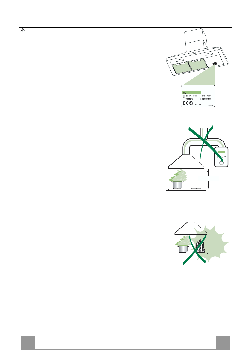
650 mm min.
The Instructions for Use apply to several versions of this appliance. Accord-
ingly, you may find descriptions of individual features that do not apply to your
specific appliance.
INSTALLATION
• The manufacturer will not be held liable for an y damages resulting fro m incorrect or impro per installat ion.
• The minimum safety distance between the cooker top and the extractor hood
is 650 mm.
• Check that the mains voltage corresponds to that indicated on the rating plate
fixed to the inside of the hood.
• For Class I appliances, check that the domestic power supply guarantees adequate earthing.
Connect the extractor to the exhaust flue through a pipe of minimum diameter
120 mm. The route of the flue must be as short as possible.
• Do not connect the extractor hood to exhaust ducts carrying combustion fumes
(boilers, fi replaces, etc.).
• If the extractor is used in conjunction with non-electrical appliances (e.g. gas
burning appliances), a sufficient degree of aeration must be guaranteed in the
room in order to prevent the backflow of exhaust gas. The kitchen must have
an opening communicating directly with the open air in order to guarantee the
entry of clea n air.
USE
• The extractor hood has been designed exclusively for domestic use to eliminate kitchen smells.
• Never use the hood f or purposes other than for which it has ben designed.
• Never leave high naked flames under the hood when it is in operation.
• Adjust the flame intensity to direct it onto the bottom of the pan only, making
sure that it does not engulf the sides.
• Deep fat fryers must be continuously monitored during use: overheated oil can
burst into flames.
• Do not flambè under the range hood; risk of fir e
• This appliance is not intended for use by persons (including children) with reduced physical, sensory or mental capabilities, or lack of experience and
knowledge, unless they have been given supervision or instruction concerning
use of the appliance by a person responsible for their safety.
• Children should be supervised to ensure that they do not play with the appliance.
MAINTENANCE
• Switch off or unplug the appliance from the mains supply before carrying out
any maintenance work.
• Clean and/or replace the Filters after the specified time p eriod.
• Clean the hood using a damp cloth and a neutral liquid deter gent.
7
7
EN
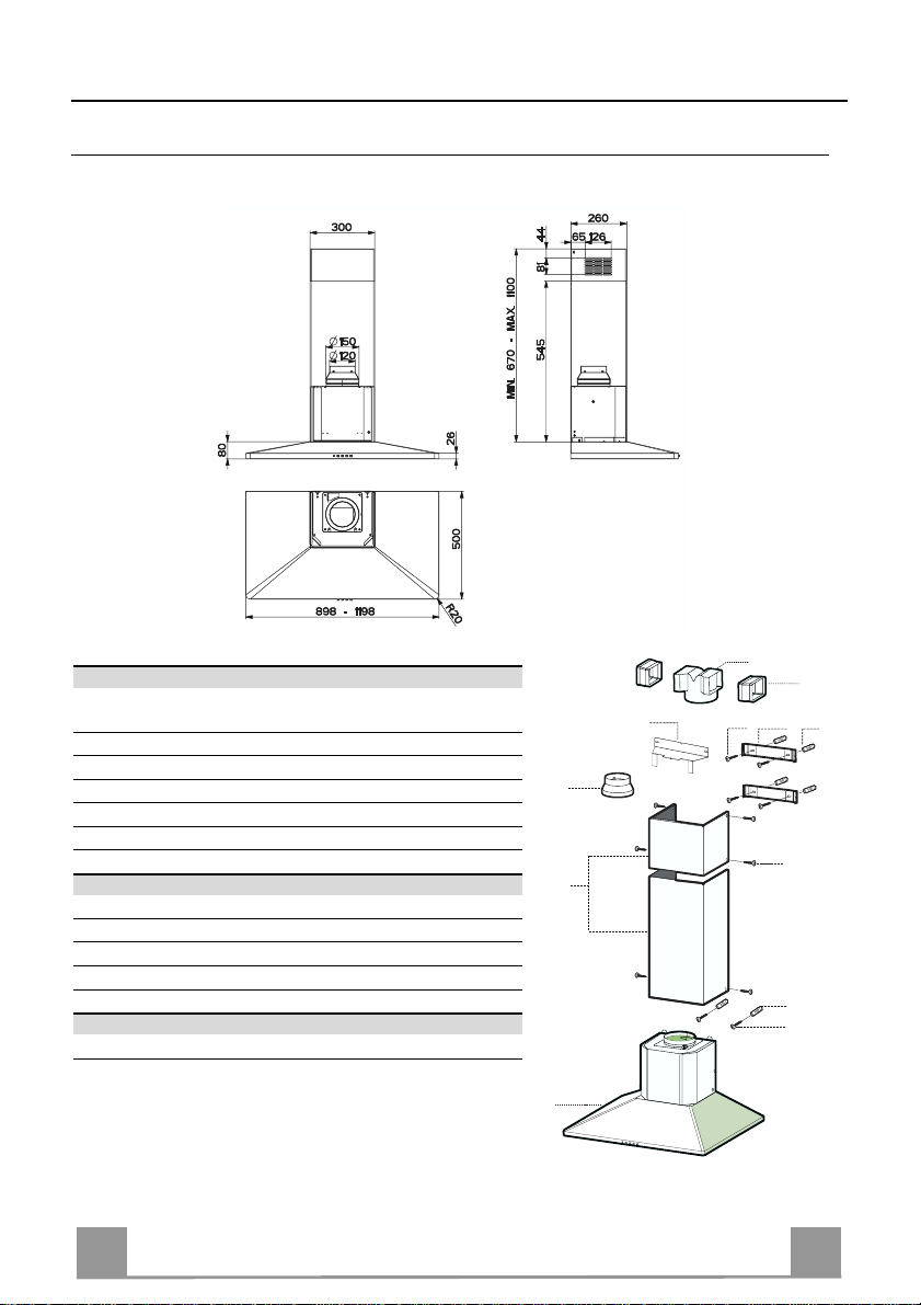
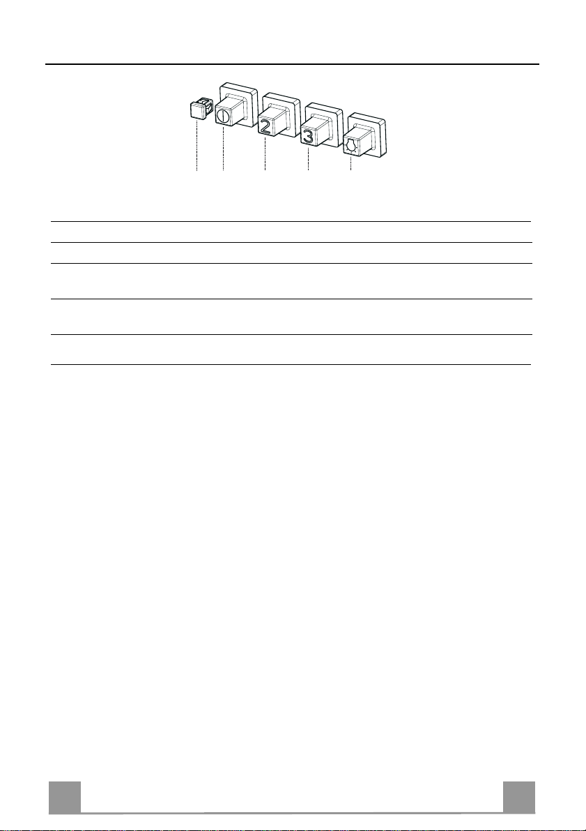
CHARACTERISTICS
Dimensions
Components
Ref. Q.ty Product Components
1 1 Hood Body, complete with: Controls, Light, Blower,
2 1 Telescopic Chimney comprising:
2.1 1 Upper Section
2.2 1 Lower Section
9 1 Reducer Flange ø 150-120 mm
14.1 2 Air Outlet Connection Extension
15 1 Air Outlet Connection
Ref. Q.ty Installation Components
7.2.1 2 Upper Chimney Section Fixing Brackets
7.3 1 Air Outlet Connection Supp ort
11 6 Wall Plugs
12a 6 Screws 4,2 x 44, 4
12c 6 Screws 2,9 x 9, 5
Q.ty Documentation
1 Instruction Manual
Filters
15
14.1
7.3
9
2.1
2
2.2
1
12a
7.2.1 11
12c
11
12a
8
8
EN
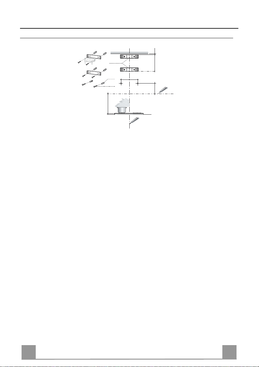
INSTALLATION
Wall drilling and bracket fixing
7.2.1
11
12a
116
116
1÷2
X
340
650 min.
Wall marking:
• Draw a vertical line on the supporting wall up to the ceiling, or as high as practical, at the
centre of the area in which the hood will be installed.
• Draw a horizontal line at 650 mm above the hob.
• P l ace bracket 7.2.1 on the wall as shown about 1-2 mm from the ceiling or upper limit aligning the centre (notch) with the vertical reference line.
• Mark the wall at the cent r es of the holes in the bracket.
• P l ace br acket 7.2.1 on the wall as shown at X mm below the first bracket (X = height of the
upper chimney section supplied), aligning the centre (notch) with the vertical line.
• Mark the wall at the cent r es of the holes in the bracket.
• Mark a reference point as in dicated at 116 mm from the vertical reference li ne and 340 mm
above the horizontal reference l ine.
• Repeat this operation on the other side.
• Drill ø 8 mm holes at all the centre points marked.
• Insert the wall plugs 11 in the holes.
• Fix the lower bracket 7.2.1 using the 12a screws (4,2 x 44,4) supplied.
• Fix the upper bracket 7.2.1 and the air outlet co nnection support 7.3 together using the 2
screws 12a (4,2 x 44,4) supplied.
• Insert the two screws 12a (4,2 x 44,4) supplied in the hood body fixing holes, leaving a gap
of 5-6 mm between the wall and the head of the screw.
9
9
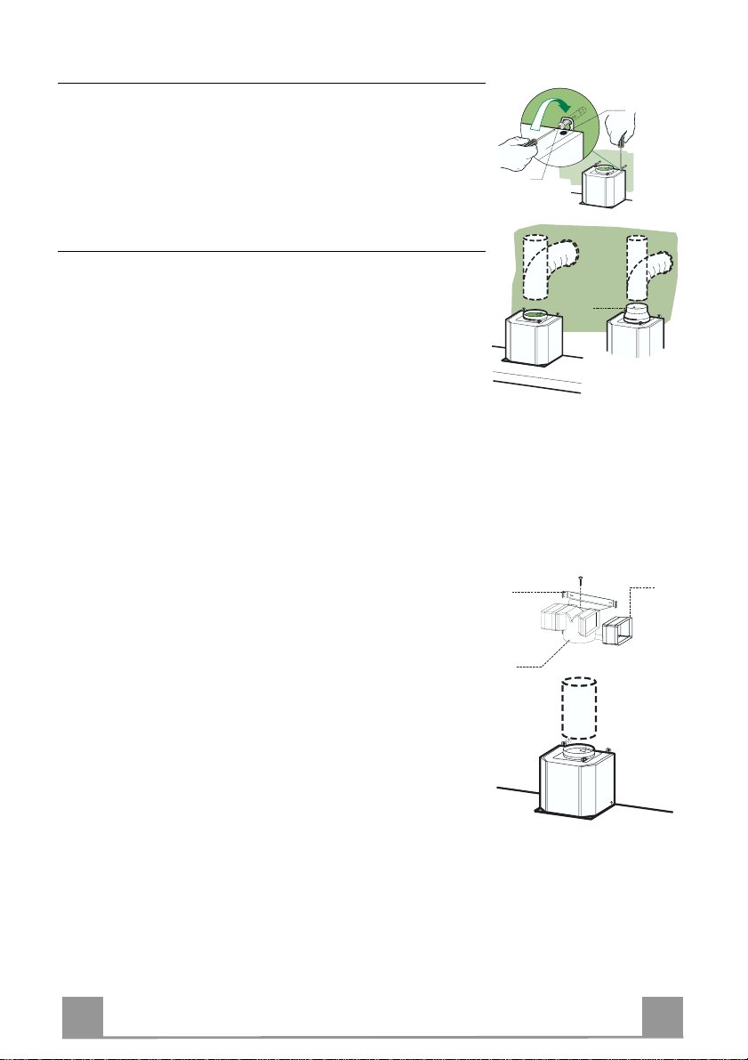
EN 110
Mounting the hood body
9
ø 120ø 150
ø 150
15
14.1
7.3
• Before attaching the hood body, tighten the two screws Vr located on the hood body mounting points.
• Hook the hood body onto the screws 12a.
• Fully tighten support screws 12a.
• Adjust screws Vr to level the hood body.
Connections
DUCTED VERSION AIR EXHAUST SYSTEM
When installing the ducted version, connect the hood to the
chimney using either a flexible or rigid pipe ø 150 or 120 mm,
the choice of which is left to the installer.
• To install a ø 120 mm air exhaust connection, insert the reducer flange 9 on the hood body outlet.
• Fix the pipe in position using sufficient pipe clamps (not supplied).
• Remove any activated charcoal filters.
Vr
12a
RECIRCULATION VERSION AIR OUTLET
• Insert the con nection extensio n pieces laterall y 14.1 in conn ection 15.
• Insert the Connector 15 i nto the Suppor t bracket 7.3 and fix it
with a screw.
• Make su re that the outlet of the extension pieces 14.1 is horizontally and vertically aligned with the chimney outlets.
• Connect the ai r outlet connection 15 to the hood body outlet
using either a flexible or rigid pipe ø 150 mm, the choice of
which is left to the installer.
• Ensure that the activated charcoal filters have been inserted.
EN 111
ELECTRICAL CONNECTION
12c
12c
12c
2.1
2.2
2
7.2.1
• Connect the hood to the mains through a two-pole switch having a contact gap of at least 3 mm.
• Re move the grease filters (see paragraph Maintenance) being
sure that the conn ector of the feeding cable is correctly inserted
in the socket placed on th e side of the fan.
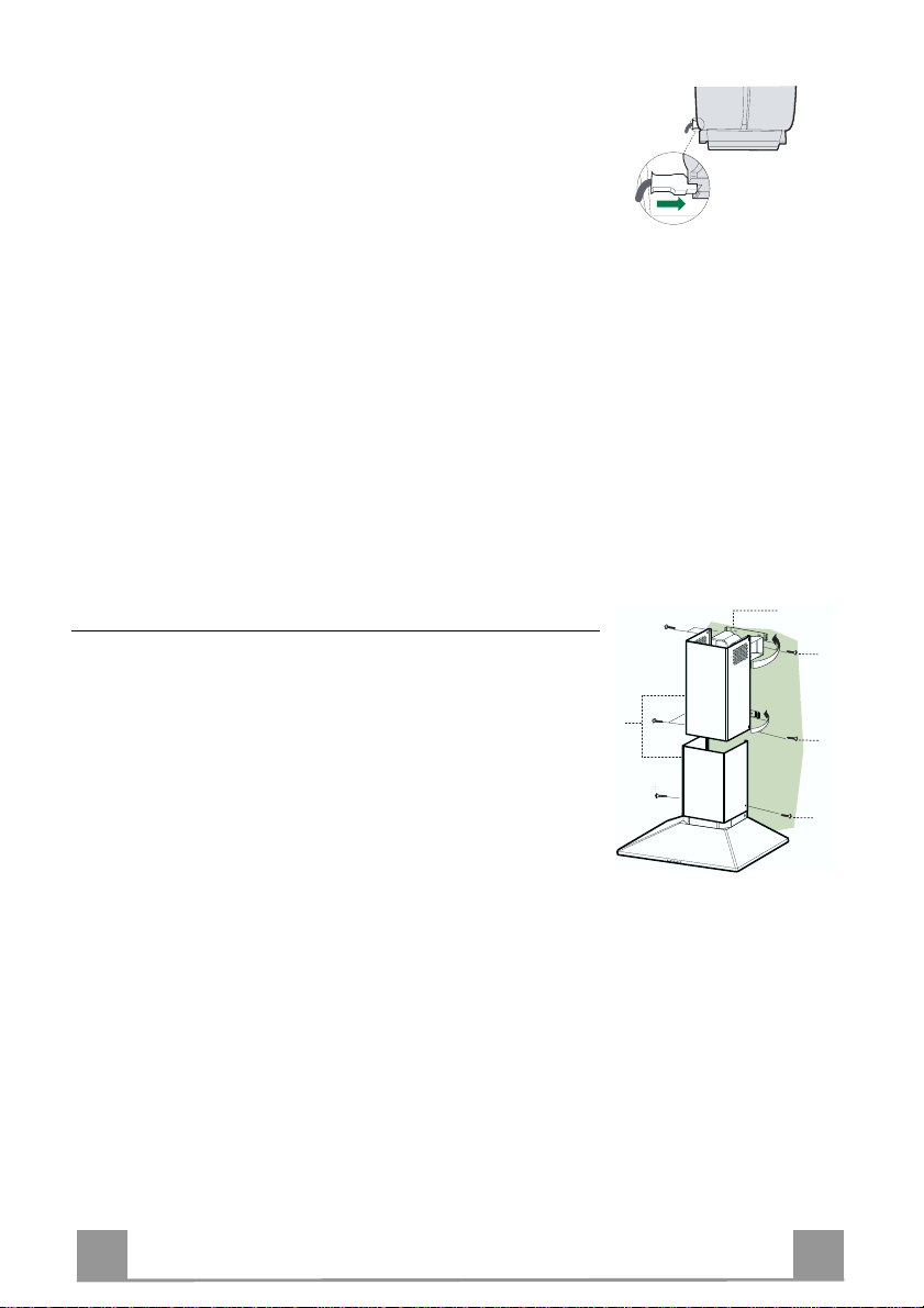
Flue assembly
Upper exhaust flue
• Slightly widen the two sides of the upper flue and hook them
behind the brackets 7.2.1, making sure that they are well
seated.
• Secure the sides to the brackets using the 4 screws 12c (2,9 x
9,5) supplied.
• Make sure that the ou tlet of the extensions pieces is align ed
with the chimney outlets.
Lower ex haust flue
• Slightly widen the two sides of the flue and hook them between the upper flue and t he wall, makin g sure that they are
well seated.
• Fix the lower part laterally to the hood body using the 2 screws
12c (2,9 x 9,5) supplied.
EN 112
USE
V1V1V1V1V1V1V1V1V1V1V1V1V1V1V1V1V1V1
S
V2
V3
L
L Light Switches the lighting system on and off.
S Led Motor running led.
V1 Motor Switches the extractor motor on and off at low speed. Used to provide a
contin-uos and silent air change in the presence of light cooking vapours.
V2 Speed Medium speed, suitable for most operating conditions given the optimum
treated air flox/noise level ratio.
V3 Intensive Maximum speed, used for eliminating the highest cooking vapour emission,
including long periods.
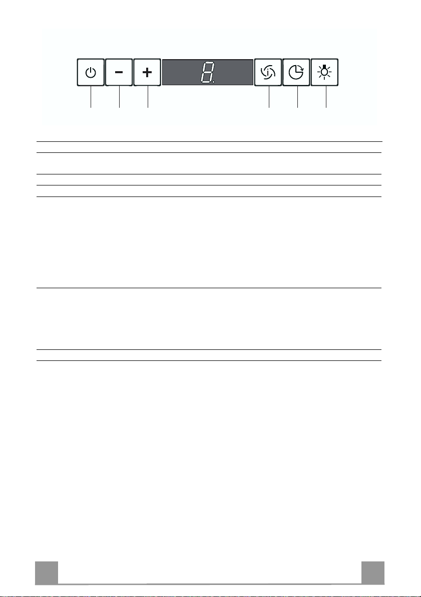
EN 113
T
T1T
3
2
T4T
5
L
Control panel
TOUCH CONTROL FUNCTION
T1 ON/OFF Motor Switches the hood motor on and off. The latest selected
speed appears on the displ ay.
T2 Speed - Decreases the suction speed: V3 → V2 → V1
T3 Speed + In creases the suction speed: V1 → V2 → V3
T4 In tensive speed Activates the intensive sp eed from any previously selected
speed. The intensive sp eed can be activated even when the
motor is OFF. By pressing the same touch control once again
or by switching off the motor this function can be deactivated. Intensive speed cannot be activated when the delay
function is on. Intensive speed has been timed at 10 minutes:
H appears on the display and a spot down on the right side
flashes once a second. After 10 minutes the system activates
automatically the latest select ed speed.
T5 Delay Activates and deactivates the delayed shutdown of the hood
(motor + lighting) at 30 minutes: the selected speed o f the
hood appears on the display and a spot down on the right
side flashes once a second. By pressing the same touch control once again or by switching off the motor delay function
can be deactivated.
L Lighting Turns light on and off.
EN 114
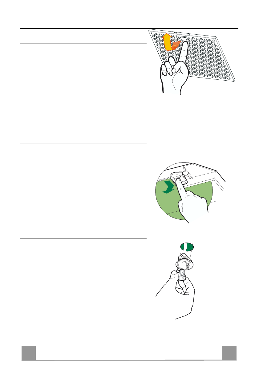
MAINTENANCE
Grease filters
CLEANING META L SELF- SUPPO RTING GREASE FILTERS
• The filters must be cleaned every 2 months of operation, or more frequently for particularly heavy usage,
and can be washed in a dishwasher.
• Remove the filters one at a time holding them up
with one hand and pulling the handle downwards
with the other hand at the same time.
• Wash the filters, taking care not to bend them. Allow
them to dry before refitting.
• When refitting the filters, make sure that the handle
is visible on the outside.
Activated charcoal filter (Recirculation version)
REPLACING THE ACTIVATED CHARCOAL FILTE R
• The filter is not washable and cannot be regenerated,
and must be replaced approximat ely every 4 months
of operation, or more frequently for particularly
heavy usage.
• Remove the metal grease filters
• Remove the saturated activated carbon filter by releasing the fixing hooks
• Fit the new filter by hooking it into its seating
• Replace the metal grease filters.
Lighting
LIGHT REPLACEMENT
20 W halogen light.
• Remove the 2 screws fixing the Lighting support, and
pull it out of from the Hood.
• Extract the lamp from the Support.
• Replace with another of the same type, making sure
that the two pins are properly inserted in the lamp
holder socket holes.
• Replace the Su pport, fixing it in place with the two
screws removed as above.
IT 115
CONSIGLI E SUGGERIMENTI
650 mm min.
Questo libretto di istruzioni per l'uso è previsto per più versioni dell' apparec-
chio. É possibile che siano descritti singoli particolari della dotazione, che non
riguardano i l Vostro apparecchio.
INSTALLAZIONE
• Il produttore declina qualsiasi responsabilità per danni dovuti ad installazione
non corretta o non conforme alle regole dell’arte.
• La distanza minima di sicurezza tra il Piano di cottura e la Cappa deve essere
di 650 mm.
• Verificare che la tensione di rete corrisponda a quella riportata nella targhetta
posta all’interno della Cappa.
• Per Apparecchi in Classe Ia accertarsi che l’impian to elettrico domestico garantisca un corretto scarico a terra.
• Collegare la Cappa all’u scita dell’a ria aspirata con tuba zione di d iametro pari o
superiore a 120 mm. Il percorso della tubazione deve essere il più breve possibile.
• Non collegare la Cappa a condotti di scarico dei fumi prodotti da combustione
(caldaie, caminetti, ecc.).
• Nel caso in cui nella stanza vengano utilizzati sia la Cappa che apparecc hi non
azionati da energia elettrica (ad esempio apparecchi utilizzatori di gas), s i deve
provvedere ad una aerazione sufficiente dell’ambien te. Se la cucina ne fosse
sprovvista, praticare un’apertura che comunichi con l’esterno, per garantire il
richiamo d’ari a pulit a.
USO
• La Cappa è stata progettata esclusivamente per uso domestico, per abbattere
gli odori della cucina.
• Non fare mai uso improprio della C appa.
• Non lasciare fiamme libere a forte intensità sotto la Cappa in funzione.
• Regolare sempre le fiamme in modo da evitare una evidente fuoriuscita laterale delle stesse rispetto al f ondo delle pe ntole.
• Controllare le friggitrici durante l’uso: l’olio surriscaldato potrebbe infiammarsi.
• Non preparare alimenti flambè sotto la cappa da cucina; pericolo d'incendio.
• Questo apparecchio non deve essere utilizzato da persone (bambini inclusi)
con ridotte capacità psichiche, sensoriali o mentali, oppure da persone senza
esperienza e conoscenza , a meno che non siano controllati o istruiti all’uso
dell’apparecchio da persone responsabili della loro sicurezza.
• I bambini devono essere supervisionati per assicurarsi che non giochino con
l’apparecchio.
MANUTENZIONE
• Prima di procedere a qualsiasi operazione di manutenzione, disinserire la
Cappa togliendo la spina elettrica o spegnendo l’interruttore generale.
• Effettuare una scrupolosa e tempestiva manutenzione dei Filtri secondo gli
intervalli consigliati.
• Per la pulizia delle supe rfici della Cappa è sufficiente utilizzare un pan no umido e detersivo liquido neut ro.
 Loading...