

Page 1
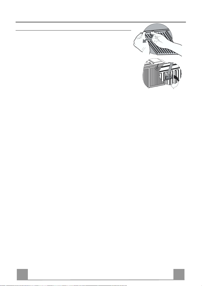
Instructions for use and installation
Istruzioni per l’uso e l’installazione
Mode d’emploi et installation
Bedienungsanleitung und Einrichtung
Kullan
ım ve montaj talimatları
GB
IT
FR
DE
TR
Cooker Hood
Cappa
Hotte de Cuisine
Dunstabzugshaube
Davlumbaz
FDMO 607 I
Page 2

EN
Instructions Manual
INDEX
RECOMMENDATIONS AND SUGGESTIONS......................................................................................................................7
CHARACTERISTICS..............................................................................................................................................................8
INSTALLATION ....................................................................................................................................................................10
USE.......................................................................................................................................................................................14
MAINTENANCE....................................................................................................................................................................15
2
2
Page 3

IT
Libretto di Istruzioni
INDICE
CONSIGLI E SUGGERIMENTI ............................................................................................................................................18
CARATTERISTICHE............................................................................................................................................................19
INSTALLAZIONE..................................................................................................................................................................21
USO......................................................................................................................................................................................25
MANUTENZIONE.................................................................................................................................................................26
3
3
Page 4

FR
Manuel d’Instructions
SOMMAIRE
CONSEILS ET SUGGESTIONS ..........................................................................................................................................29
CARACTERISTIQUES.........................................................................................................................................................30
INSTALLATION ....................................................................................................................................................................32
UTILISATION........................................................................................................................................................................36
ENTRETIEN..........................................................................................................................................................................37
4
4
Page 5

DE
Bedienungsanleitung
INHALTSVERZEICHNIS
EMPFEHLUNGEN UND HINWEISE....................................................................................................................................40
CHARAKTERISTIKEN..........................................................................................................................................................41
MONTAGE............................................................................................................................................................................43
BEDIENUNG.........................................................................................................................................................................47
WARTUNG............................................................................................................................................................................48
5
5
Page 6

TR
Kullanim Kilavuku
IÇERIKLER
TAVSIYELER VE ÖNERILER ..............................................................................................................................................51
ÖZELLIKLER........................................................................................................................................................................52
MONTAJ...............................................................................................................................................................................54
KULLANIM............................................................................................................................................................................58
BAKIM...................................................................................................................................................................................59
6
6
Page 7

EN
RECOMMENDATIONS AND SUGGESTIONS
650 mm min.
The Instructions for Use apply to several versions of this appliance. Accord-
ingly, you may find descriptions of individual features that do not apply to your
specific appliance.
INSTALLATION
• The manufacturer will not be held liable for an y damages resulting fro m incorrect or impro per installat ion.
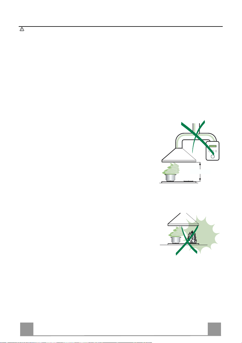
• The minimum safety distance between the cooker top and the extractor hood
is 650 mm.
• Check that the mains voltage corresponds to that indicated on the rating plate
fixed to the inside of the hood.
• For Class I appliances, check that the domestic power supply guarantees adequate earthing.
Connect the extractor to the exhaust flue through a pipe of minimum diameter
120 mm. The route of the flue must be as short as possible.
• Do not connect the extractor hood to exhaust ducts carrying combustion fumes
(boilers, fi replaces, etc.).
• If the extractor is used in conjunction with non-electrical appliances (e.g. gas
burning appliances), a sufficient degree of aeration must be guaranteed in the
room in order to prevent the backflow of exhaust gas. The kitchen must have
an opening communicating directly with the open air in order to guarantee the
entry of clea n air.
USE
• The extractor hood has been designed exclusively for domestic use to eliminate kitchen smells.
• Never use the hood f or purposes other than for which it has ben designed.
• Never leave high naked flames under the hood when it is in operation.
• Adjust the flame intensity to direct it onto the bottom of the pan only, making
sure that it does not engulf the sides.
• Deep fat fryers must be continuously monitored during use: overheated oil can
burst into flames.
• Do not flambè under the range hood; risk of fir e
• This appliance is not intended for use by persons (including children) with reduced physical, sensory or mental capabilities, or lack of experience and
knowledge, unless they have been given supervision or instruction concerning
use of the appliance by a person responsible for their safety.
• Children should be supervised to ensure that they do not play with the appliance.
MAINTENANCE
• Switch off or unplug the appliance from the mains supply before carrying out
any maintenance work.
• Clean and/or replace the Filters after the specified time p eriod.
• Clean the hood using a damp cloth and a neutral liquid deter gent.
7
7
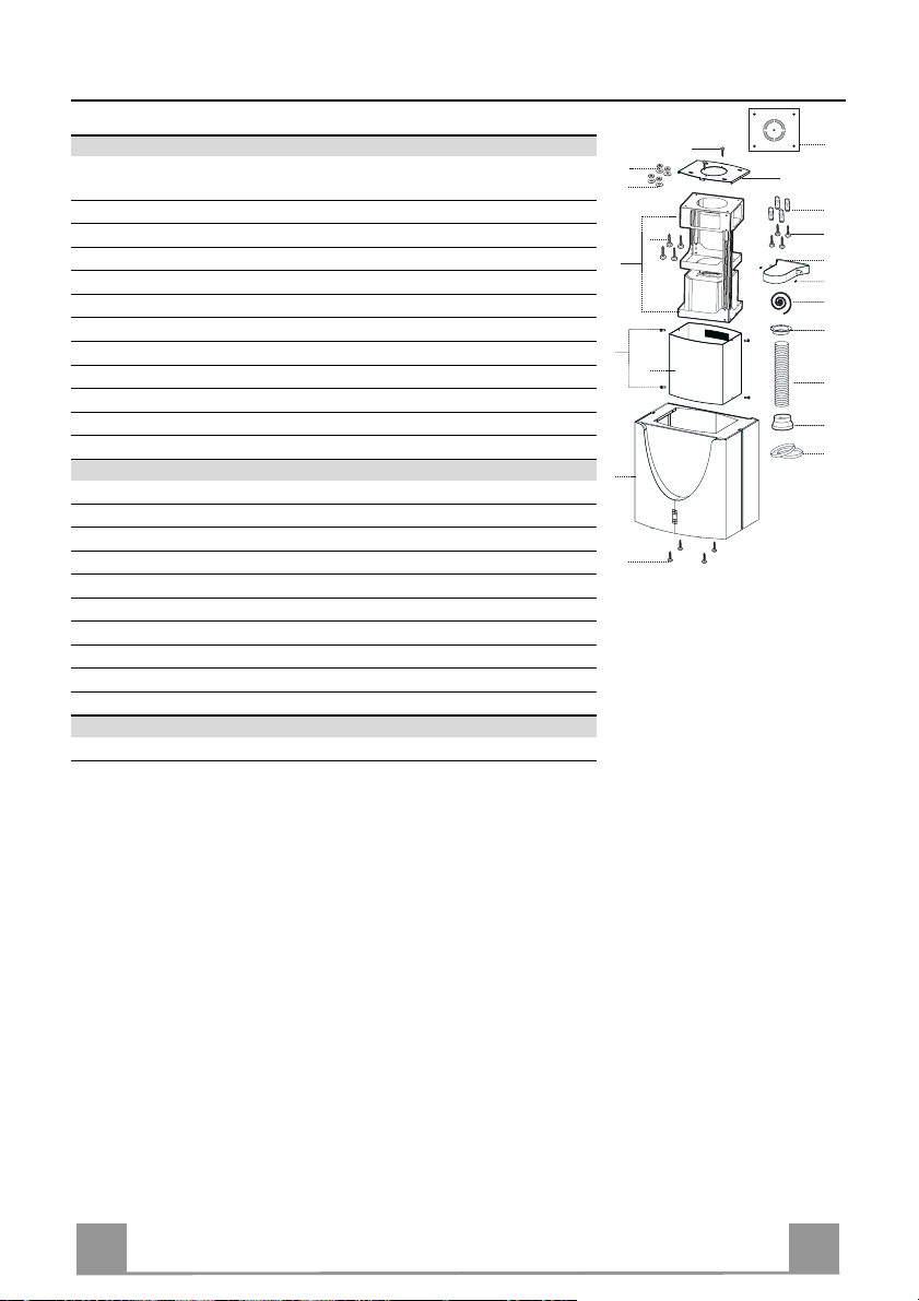
Page 8
EN
CHARACTERISTICS
24
15
29
9
2
12c
1
25
14
11
12h
21
23
22
7.1
7.1b
7.1a
12g
12f
26
12w
13
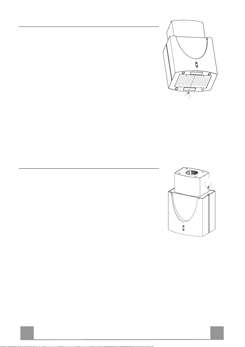
Components
Ref. Q.ty Product Components
1 1 Hood Body, complete with: C ontrols, Light, Blower, Filters
2 1 Upper Chimney
7.1 1 Telescopic f rame complete with extrac tor, consist ing of:
7.1a 1 Upper frame
7.1b 1 Lower frame
9 1 Reducer Flange ø 150-120 mm
13 1 Gasket
14 1 Hood Body Air Out let Extension Piece
15 1 Air Outlet Connection
25 2 Pipe clamps
26 1 Fixing Part of the upper Chimney
29 1 Air outlet connection tube
Ref. Q.ty Installation Components
11 4 Wall Plugs ø 10
12c 4 Screws 2,9 x 9, 5
12f 4 Screws M6 x 15
12g 4 Screws M6 x 80
12h 4 Screws 5,2 x 70
12w 2 Screws M3 x 8
21 1 Drilling template
22 4 6.4 mm int. dia washers
23 4 M6 nuts
24 2 Fixing knobs f or the air outlet connection piece
Q.ty Documentation
1 Instruction Manual
8
8
Page 9
EN
Dimensions
**
*
* Dimensions of the hood in ducting version.
** Dimensions of the hood in recycling version.
9
9
Page 10
EN 110
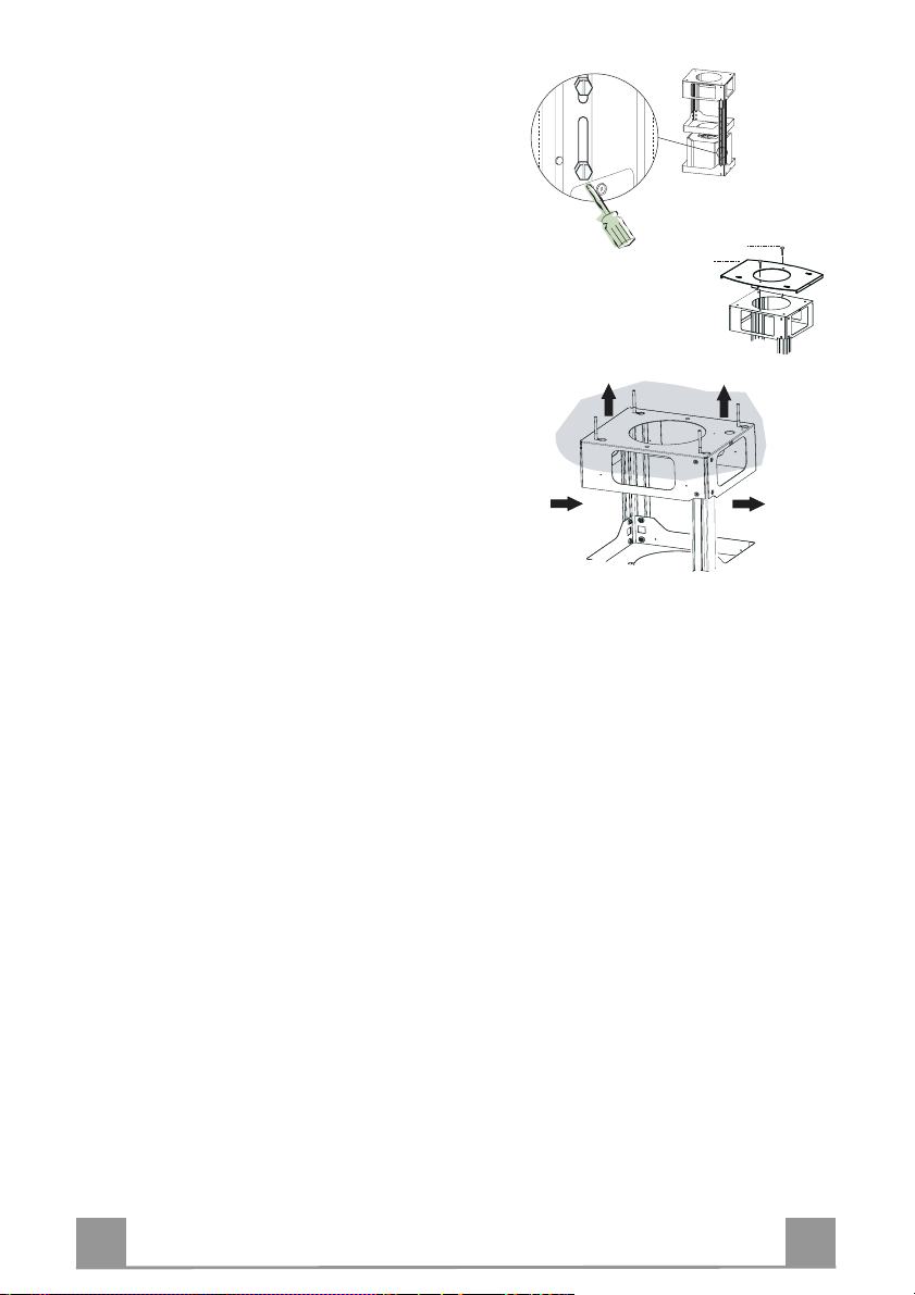
INSTALLATION
Drilling the Ceiling/shelf and fixing the frame
DRILLING THE CEILING/SHELF
• Use a plumb line to mark the centre of the hob on the ceiling/support shelf.
• Place the drilling template 21 provided on the ceiling/support shelf, making sure that the
template is in the correct position by lining up the axes of the template with those of the hob.
• Mark the centres of the holes in the template.
• Drill the holes at the points marked:
• For concrete ceilings, drill for plugs appropriate to the screw size.
• For hollow brick ceilings with wall thickness of 20 mm: drill ø 10 mm(immediately insert
the Dowels 11 supplied).
• For wooden beam ceilings, drill according to the wood screws used.
• For wooden shelf, drill ø 7 mm.
• For the power supply cable feed, drill ø 10 mm.
• For the air outlet (Ducted Versio n), drill according to t he diameter of the external air exhaust duct connection.
• Insert two screws of the following type, crossing them and leaving 4-5 mm from the ceiling:
• For concrete ceilings, use the appropriate plugs for the screw size (not provided).
• for Cavity ceiling with inner space, with wall thickness of approx. 20 mm, Screws 12h,
supplied.
• For wooden beam ceilings, use 4 wood screws (not provided).
• For wooden shelf, use 4 screws 12g with washers 22 and nuts 23, provided.
Page 11
EN 111
FIXING THE FRAME
quired, then
If you wish to adjust the height of the frame, pro ceed
as follows:
• Unfasten the metric screws joining the two columns,
located at the sides of the frame.
• Adjust the frame to the height re
replace all the screws removed as above.
• Fix the Fixing Part of the Upper Chimney 26 to th e
hanging kit using the 2 screws 12w (M3 x 8).
• Lift up the frame, fit the frame slots onto the screws
up to the slot end positions.
• Tighten the two screws and fasten the other two
screws provided; before locking the screws com-
pletely, it is possible to adjust the frame by turning it,
making sure that the screws do not come out of their
housing in the adjustment slot.
• The Frame must be securely fasten ed so as to sup port
both the weight of the Hood and the stress caused by
occasional axial pressure against the fitted Appliance. After fixing, make sure that the base is stable
even when the Frame is subjected to lateral stress.
• If the Ceiling is no t strong enough in the area where
the hood is to be fixed, the Installer must strengthen
the area using suitable plates and counterplates anchored to resistant structures.
12w
26
1
2
1
2
Page 12
EN 112
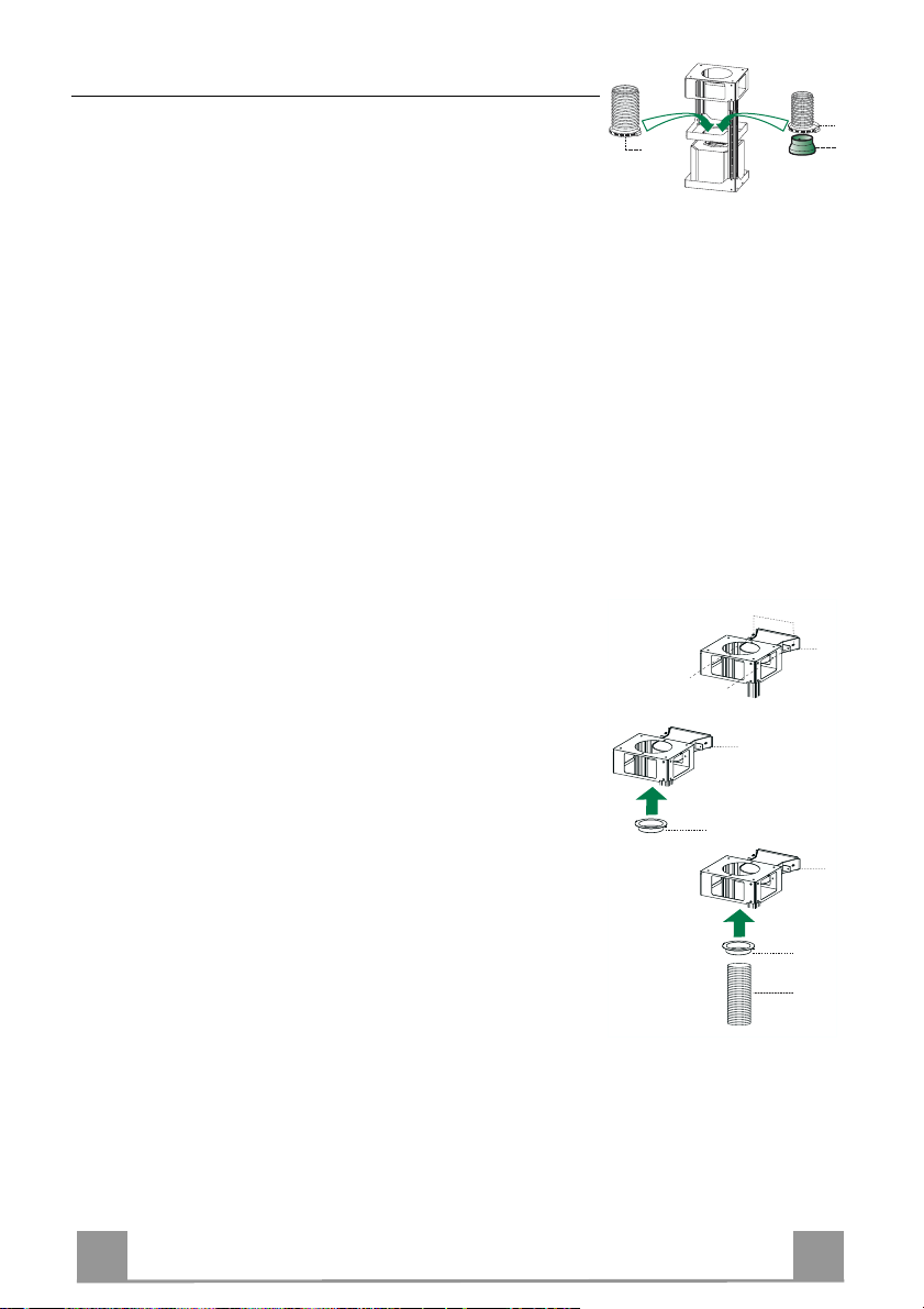
Ducted version air exhaust system Connection
9
ø 150
ø 120
25
25
14
15
24
15
14
15
29
When installing the ducted version, connect the hood to the
chimney using either a flexible or rigid pipe ø 150 or 120 mm,
the choice of which is left to the installer.
• To install a ø 120 mm air exhaust connection, insert the reducer flange 9 on the hood body outlet.
• Fix the pipe using the pipe clamps 25 provided.
• Remove any activated charco al filters.
AIR OUTLET – RECIRCULATION VERSION
• Fasten the Air Outlet Connector 15 to the upper frame using
the 2 knobs 24.
• Attach the Air Outlet Connecto r Flange 14 to the Air Outlet
Connector 15.
• Connect the two outlets using the Air Outlet Connector Pipe
29.
Page 13
EN 113
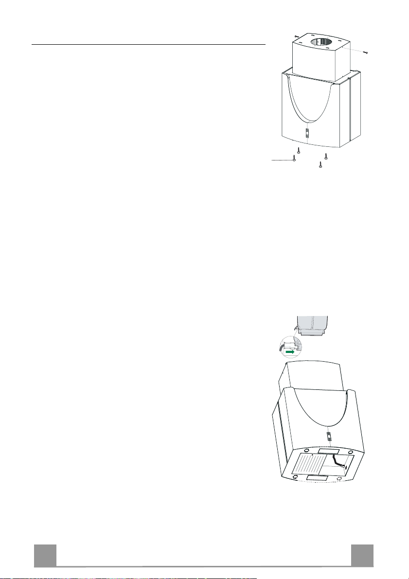
Fitting the Chimney and Fixing the Hood Canopy
12c
12f
• Insert the Top chimney with the slots facing upwards when
installing the recirculation version, or vice versa with the slots
facing downwards when installing the ducting version, then fix
the top part to the Upper Chimney Connector using the screws
12c (2.9 x 9.5) provided.
Recirculation version
• Make sure that the Air Outlet Connector 15 is positioned in
correspondence with the Chimney Grill.
• If this is not the case, remove the chimney and adjust the position of the Air Outlet Connector 15; replace the components as
described above.
Before fixing the Hood Canopy to the Frame:
• Remove the metal grease filters from the hood canopy.
• Remove any activated charcoal odour filters.
• Fix the ho od canopy to the frame p rovided, working fro m below and using the 4 screws 12f supplied.
ELECTRICAL CONNECTION
• Connect the hood to the mains through a two-pole switch having a contact gap of at least 3 mm.
• Re move the grease filters (see paragraph Maintenance) being
sure that the conn ector of the feeding cable is correctly inserted
in the socket placed on th e side of the fan.
• Join the connector s.
• Install the odour filter and the charcoal filter in case the hood is
to be used in recycling version.
• Install the grease filter again.
Page 14
EN 114
USE
A
B
D
C
E
GH
F
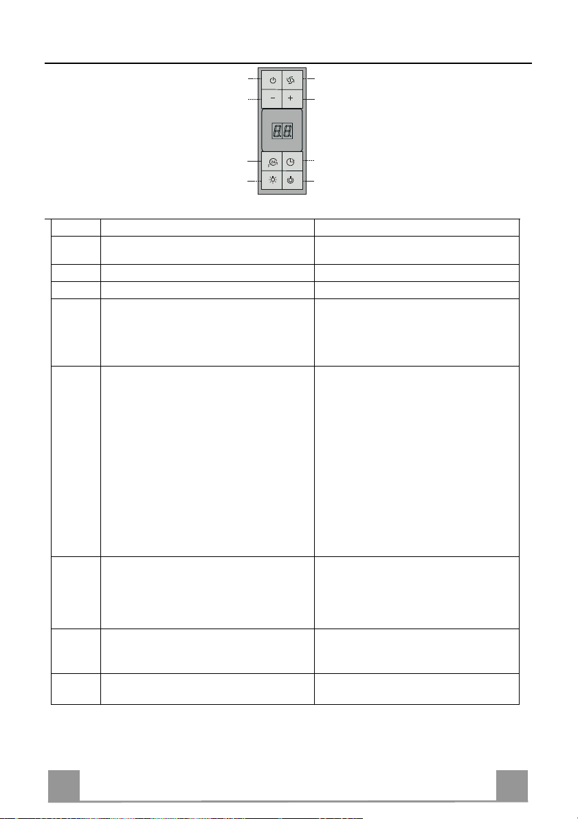
Control panel
Button Function Display
Turns the suction motor on and off at th e last
A
Displays the speed set
speed used.
B Decrease the working speed.
C Increase the working speed.
Activates intensive speed from any other
D
speed even wi th the motor off . This speed i s
Displays HI and the bottom right hand spot
flashes once a second.
timed to run for 10 minutes, after which the
system retu rns to th e previ ous sp eed. Su itable
to deal with maximum cooking fumes.
Activates the motor at a speed that allows
E
extraction of 100 m
3
/h for 10 minutes every
hour, after which the motor stops.
When the filt er alarm is on, pres s the button
for approximately 3 seconds to reset the
alarm. These indications are only visible
Displays 24 and the bottom right hand spot
flashes, while the motor is turned on
On completing the procedure the previous
indicator is turned off:
FF indicates that the metal grease filters
when the motor is turned off.
EF indicates that the activated charcoal
Activates automatic shutdown after 30’. Suit-
F
able to complete elimination of residual
odours. Can be activated from any position,
Alternately displays the working speed and
the time remaining before the hood turns
off. The bottom right hand spot flashes.
and is turned off by pressing the button or
switching the motor off.
Turns the lighting system (spots) on and off.
G
Press and hold for 2 sec onds to turn the Room
Lights on and off.
Turns the reduced intensity lighting system
H
(spots) on and off.
need washing. The alarm is triggered
after the Hood has been in operation
for 100 hours.
filter needs changing and the metal
grease filters need washing. The
alarm is triggered after the Hood has
been in operation for 200 hours.
Page 15
EN 115
MAINTENANCE
Metal grease filters
Filters can be washed in the dish machine. They need to be
washed when FF-sign appears on the display or in any case every
2 months, or even more frequently in case of particularly intensive use of the hood.
Alarm reset
• Switch off the hood and the lights. If the 24h-function has been
activated this has to be deactivated.
• Press the E-key till the display is unlit.
Cleaning the filters
• Unhook filters one by one. supporting the filters with one hand,
act on the knob (pull and rotate) and then take off the security
spring.
• Wash the filters, taking care not to bend them. Allow them to
dry before refitting.
• Reassemble the filters, paying attention on replacing the security spring.
Page 16
EN 116
Charcoal filter (recycling version)
• This filter cannot be washed or regenerated. It must be replaced when the EF appears on the
display or at least once every 4 months.
Activation of the alarm signal
• In the recycling version hoods the filter saturation alarm must be activated during the installation or later.
• Switch off the hood and the lights.
• Disconnect the hood from the mains supply.
• When restoring the connection press and hold B-key.
• When releasing the key t wo rotating rectangles appear on the display.
• Within 3 seconds press the B-key until a flashing confirmation appears on the dispaly:
• 2 flashes with EF - charcoal filter saturation alarm ACTIVATED
• 1 flash with EF - charcoal filter saturation alarm DEACTIVATED.
REPLACING THE CHARCOAL FILTER
Reset of the alarm signal
• Switch off the hood and the lighting. If the 24h-function has
been activated this has to be deactivated.
• Press the E-key until the display is unlit.
Replacing of the filter
• Remove the metal grease filters.
• Remove the saturated charcoal filter by releasing the fixing
hooks
• Fit the new filter and fasten it in its correct position.
• Put the metal grease filters in their seats.
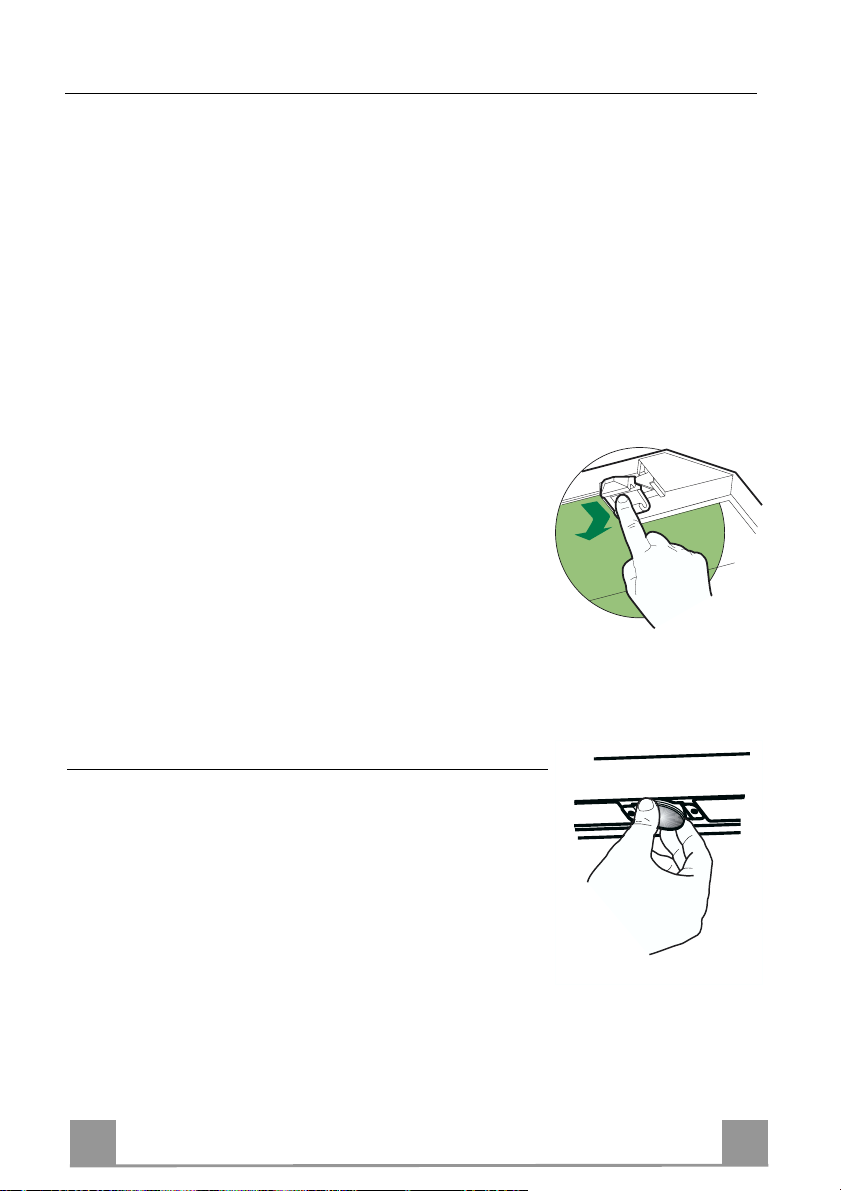
Lighting
LIGHT REPLACEMENT
20 W halogen light.
• Extract the lamp from the lamp holder by pulling gently.
• Replace with another of the same type, making sure that the
two pins are properly inserted in the lamp holder socket holes.
Page 17
EN 117
Lighting
CHANGING THE LAMPS
11W neon lamps
• Remove the Metal grease filters.
• Unfasten the screw fixing the Neon cover, and unhook the
cover from the hood canopy.
• Change the lamp and insert a new one of the same type.
• Replace the Cover.
• Replace the Metal grease filters.
Lighting
CHANGING A LED
• Unfasten the screws fixing the Led cover.
• Lift the cover and unfasten the connector.
• Re move the Led fro m the cover and replace it with a n ew one
of the same type.
• Fit the new Led in th e cov er, fast en u p th e conn ecto r again an d
replace the cover, using th e screws removed as above.
Page 18
IT 118
CONSIGLI E SUGGERIMENTI
650 mm min.
Questo libretto di istruzioni per l'uso è previsto per più versioni dell' apparec-
chio. É possibile che siano descritti singoli particolari della dotazione, che non
riguardano i l Vostro apparecchio.
INSTALLAZIONE
• Il produttore declina qualsiasi responsabilità per danni dovuti ad installazione
non corretta o non conforme alle regole dell’arte.
• La distanza minima di sicurezza tra il Piano di cottura e la Cappa deve essere
di 650 mm.
• Verificare che la tensione di rete corrisponda a quella riportata nella targhetta
posta all’interno della Cappa.
• Pe r Apparecchi in Classe Ia accertarsi ch e l’impianto elettrico domestico garantisca un corretto scarico a terra.
• Collegare la Cappa all’u scita dell’a ria aspirata con tuba zione di d iametro pari o
superiore a 120 mm. Il percorso della tubazione deve essere il più breve possibile.
• Non collegare la Cappa a condotti di scarico dei fumi prodotti da combustione
(caldaie, caminetti, ecc.).
• Nel caso in cui nella stanza vengano utilizzati sia la Cappa che apparecc hi non
azionati da energia elettrica (ad esempio apparecchi utilizzatori di gas), s i deve
provvedere ad una aerazione sufficiente dell’ambien te. Se la cucina ne fosse
sprovvista, praticare un’apertura che comunichi con l’esterno, per garantire il
richiamo d’ari a pulit a.
USO
• La Cappa è stata progettata esclusivamente per uso domestico, per abbattere
gli odori della cucina.
• Non fare mai uso improprio della C appa.
• Non lasciare fiamme libere a forte intensità sotto la Cappa in funzione.
• Regolare sempre le fiamme in modo da evitare una evidente fuoriuscita laterale delle stesse rispetto al f ondo delle pe ntole.
• Controllare le friggitrici durante l’uso: l’olio surriscaldato potrebbe infiammarsi.
• Non preparare alimenti flambè sotto la cappa da cucina; pericolo d'incendio.
• Questo apparecchio non deve essere utilizzato da persone (bambini inclusi)
con ridotte capacità psichiche, sensoriali o mentali, oppure da persone senza
esperienza e conoscenza , a meno che non siano controllati o istruiti all’uso
dell’apparecchio da persone responsabili della loro sicurezza.
• I bambini devono essere supervisionati per assicurarsi che non giochino con
l’apparecchio.
MANUTENZIONE
• Prima di procedere a qualsiasi operazione di manutenzione, disinserire la
Cappa togliendo la spina elettrica o spegnendo l’interruttore generale.
• Effettuare una scrupolosa e tempestiva manutenzione dei Filtri secondo gli
intervalli consigliati.
• Per la pulizia delle supe rfici della Cappa è sufficiente utilizzare un pan no umido e detersivo liquido neut ro.
Page 19
IT 119
CARATTERISTICHE
24
15
29
9
2
12c
1
25
14
11
12h
21
23
22
7.1
7.1b
7.1a
12g
12f
26
12w
13
Componenti
Rif. Q.tà Componenti di Prodotto
1 1 Corpo Cappa completo di: Comandi, Luce,Gruppo Ventilatore,
2 1 Camino Superiore
7.1 1 Traliccio telescopico completo di Aspi ratore,for mato da:
7.1a 1 Traliccio superiore
7.1b 1 Traliccio inferiore
9 1 Flangia di Riduz ione ø 150-1 20 mm
13 1 Guarnizione Adesiva Novastik
14 1 Flangia per Raccordo Uscita Aria
15 1 Raccordo Uscita Aria
25 2 Fascette stringitubo
26 1 Attacco Camino Superiore
29 1 Tubo Raccordo Usc it a Aria
Rif. Q.tà Componenti di Installazione
11 4 Tasselli ø 10
12c 4 Viti 2,9 x 9,5
12f 4 Viti M6 x 10
12g 4 Viti M6 x 80
12h 4 Viti 5,2 x 70
12w 2 Viti M3 x 8
21 1 Dima di foratura
22 4 Rondelle øi 6,4
23 4 Dadi M6
24 2 Pomelli fissaggio Raccordo Uscita Aria
Q.tà Documentazione
1 Libretto Istruzioni
Filtri, Camino Inferiore
Page 20

IT 220
Ingombro
**
*
* Dimensioni per cappa in versione aspirante.
** Dimensioni per cappa in versione filtrante.
Page 21

IT 221
INSTALLAZIONE
Foratura Soffitto/Mensola e Fissaggio Traliccio
FORATURA SOFFITTO/MENSOLA
• Con l’ausilio di un Filo a piombo riportare sul Soffitto/Mensola di supporto il centro del
Piano di Cottura.
• Appoggiare al Soffitto/Mensola la Dima di Foratura 21 in dotazione, facendo coincidere il
suo centro al centro proiettato e allineando gli assi della Dima agli assi del Piano di Cottura.
• Segnare i centri dei Fori della Dima.
• Forare i punti seguenti:
• Soffitto in Calcestruzzo massiccio: secondo Tasselli per Calcestruzzo impiegati.
• Soffitto in Laterizio a camera d’aria, con spessore resistente di 20 mm: ø 10 mm (inserire
subito i Tasselli 11 in dotaz ione ) .
• Soffitto in Travatura di Legno: secondo Viti per Legno impiegate.
• Mensola in Legno: ø 7 mm.
• Passaggio del Cavo elettrico di Alimentazione: ø 10 mm.
• Uscita Aria (Versione Aspirante): secondo diametro del collegamento alla Tubazione di
Evacuazione Esterna.
• Avvitare, incrociandole e lasciando 4-5 mm dal soffitto, due viti:
• per Calcestruzzo massiccio, Tasselli per Calcestruzzo, non in dotazione.
• per Laterizio a camera d’ari a, con sp essore resisten te di 2 0 mm circa, Viti 12h, in dotazio-
ne.
• per Travatura di legno, Viti per legno, non in dotazione.
• per Mensola in Legno, viti 12g con Rondelle 22 e Dadi 23, in dotazione.
Page 22

IT 222
FISSAGGIO TRALICCIO
Nel caso in cui si voglia rego lare l’altezza del traliccio :
• Svitare le viti che uniscono le due colonne.
• Regolare il traliccio all’altezza d esiderata e riavvi tare
le viti.
• Unire l’Attacco Camino Superiore 26 al traliccio superiore tramite le 2 Viti 12w (M3 x 8).
• Sollevare il traliccio, incastrare le asole sulle viti e
scorrere fino a battuta. A questo punto il traliccio si
regge da solo
• Stringere le due viti e avvitare le altre due in dotazione sulla piastra superiore;
Prima di serrare definitivamente le viti è possibile
effettuare delle regolazioni spostando il traliccio,facendo attenzione che le viti non escano dalla
sede dell’asola di regolazione.
• Il fissaggio del Traliccio deve essere sicuro in relazione sia al peso della Cappa sia alle sollecitazioni
causate da occasionali spinte laterali all’Apparecchio
montato. A fissaggio avvenuto verificare quindi che
la base sia stabile an che se il Traliccio è sollecitato a
flessione.
• In tutti i casi in cui il Soffitto non fosse sufficientemente robusto sul punto di sospensione, l’Installatore
dovrà provvedere a irrobustirlo con opportune piastre
e contropiastre ancorate a p arti strutturalmente resistenti.
12w
26
1
2
1
2
Page 23

IT 223
Connessione Uscita aria Versione Aspirante
9
ø 150
ø 120
25
25
14
15
24
15
14
15
29
Per installazione in Versione Aspirante collegare la Cappa alla
tubazione di uscita per mezzo di un tubo rigido o flessibile di
ø 150 o 120 mm, la cui scelta è lasciata all’installatore.
• Per collegamento con tubo ø 120 mm, inserire la Flangia di
riduzione 9 sull’Uscita del Corpo Cappa.
• Fissare il tubo con adeguate fascette stringitubo 25 in dotazione.
• Rimuovere eventuali filtri al carbone attivo.
USCITA ARIA VERSIONE FILTRANTE
• Attaccare il Raccordo Uscit a Aria 15 al traliccio superiore tramite i 2 Pomelli 24.
• Attaccare la Flan gia Raccordo Uscita Aria 14 al Raccordo Uscita Aria 15.
• Collegare le due uscite co l Tub o Raccordo Uscita Aria 29.
Page 24

IT 224
Montaggio Camino e Fissaggio Corpo Cappa
12c
12f
• Inserire il Camino superiore con le asole verso l’alto in caso di
installazione della cappa in versione filtrante, viceversa con le
asole verso il basso in caso di installazione in versione aspirante e fissarlo nella parte superiore all’Attacco Camino Superiore
con le Viti 12c (2,9 x 9,5) in dotazione.
Versione filtrante
• Assicurarsi che il Raccordo Uscita Ari a 15 sia in corrispondenza della Grigliatura del Camino.
• Se così non fosse, rimuovere il camino e aggiustare la posizione del Raccordo Uscita Aria 15; rimontare quindi i particolari
come prima descritto.
Prima di fissare il Corpo Cappa al Traliccio:
• Togliere i Filtri antigrasso dal Corpo Cappa.
• Togliere eventuali Filtri Antiodore al Carbone attivo.
• Fissare quindi dal sotto, con 4 viti 12f in dotazione, il Corpo
Cappa al Traliccio predisposto.
CONNESSIONE ELETTRICA
• Collegare la Cappa all’Alimentazione di Rete interponendo un
Interruttore bipolare con apertura dei contatti di almeno 3 mm.
• Rimuovere i Filtri antigrasso (vedi par. “Manutenzione”) e assicurarsi che il connettore del Cavo di alimentazione sia correttamente inserito nella presa dell’Aspiratore.
• Effettuare i collegamenti dei Connettori.
• Per la Versione Filtrante montare il Filtro Antiodore al Carbone attivo.
• Rimontare i Filtri Antigrasso.
Page 25

IT 225
USO
A
B
D
C
E
GH
F
Quadro comandi
Tasto Funzione Display
Accende e spegne il motore di aspirazione
A
Visualizza la velocità impostata
all’ultima velocità utilizzata.
B Decrementa la velocità di eser cizio.
C Incrementa la velocità di esercizio.
Attiva la velocità intensiva da qualsiasi velocità
D
anche da motore spento, tale velocità è temporiz-
Visualizza HI e il punto in basso a destra
lampeggia una volta al secondo.
zata a 10 minuti, al termine del tempo il sistema
ritorna alla velocità precedentemente impostata.
Adatta a front eggiare le mass ime emissi oni di fumi di cottura.
Attiva il motore ad una velocità che consente
E
un’aspirazione di 100 m
3
/h per 10 minuti ogni ora,
terminati il motore si ferma.
Con l’allarme filtri in corso premendo il tasto per
circa 3 secondi si effettua il reset dell’al-larme.
Tali segnalazioni sono visibili solo a motore spento.
Visualizza 24 e il punto in basso a destra
lampeggia, mentre il motore è in funzione
Terminata la procedura si spegne la segnalazione prec edentemente visualizzata:
FF segnala la necessità di lavare i filtri
antigrasso metallici. L’allarme entra
in funzione dopo 100 ore di lavoro effettivo della Cappa.
EF segnala la necessità di sostituire i filtri
al carbone attivo e devono anche essere lavati i fi ltri antigrasso met allici.
L’allarme ent ra in funzion e dopo 200
ore di lavoro effett ivo della Cappa.
Attiva lo spegnimento automatico ritardato di 30’.
F
Adatto per completare l’eliminazione di odori
residui. Attivabile da qualsiasi posizione, si disattiva premendo il tasto o spegnendo il motore.
Accende e spegne l’impianto di illuminazione
G
Visualizza alternativamente la velocità di
esercizio e il tempo rimanente allo spegnimento della cappa. Il punto in basso a destra lampeggia.
(Faretti). Tenendolo premuto per 2 secondi accende e spegne le Luci Ambiente.
Accende e spegne l’impianto di illuminazione ad
H
intensità ridotta (Faretti).
Page 26

IT 226
MANUTENZIONE
Filtri antigrasso metallici
Sono lavabili anche in lavastoviglie, e necessitano di essere lavati
quando sul display appare FF o almeno ogni 2 mesi circa di utilizzo o più frequentemente, per un uso particolarmente intenso.
Reset del segnale di allarme
• Spegnere le Luci e il Motore di aspirazione, quindi qualora
fosse attivata la funzione 24h disattivarla.
• Premere il tasto E sino allo spegnersi del display.
Pulizia Filtri
• Sganciare i Filtri uno alla volta. Sostenendolo con una mano
agire sull’apposito pomello (tirare e ruotare) e successivamente
staccare la molla di sicurezza.
• Lavare i Filtri evitando di piegarli, e lasciarli asciugare prima
di rimontarli.
• Rimontarli avendo cura di riposizionare la molla di sicurezza.
Page 27

IT 227
Filtri antiodore al Carbone attivo (Versione Filtrante)
• Non è lavabile e non è rigenerabile, va sostituito quando sul display appare EF o almeno
ogni 4 mesi.
Attivazione del segnale di allarme
• Nelle Cappe in Versione Filtrante, la segnalazione di Allarme saturazione Filtri va attivata al
momento dell’installazione o successivamente.
• Spegnere le Luci e il Moto re di aspirazione.
• Scollegare la cappa dall’alimentazione di rete.
• Ripristinare il collegamento tenendo premuto il tasto B.
• Rilasciando il tasto sul display compaiono due rettangoli in rotazione.
• Entro 3 secondi premere il Tasto B sino alla conferma che appare sul display:
• 2 lampeggi scritta EF - Allarme saturazione Filtro Carbone attivo ATTIVATO
• 1 lampeggio scritta EF - Allarme saturazione Filtro al Carbone attivo DISATTIVATO.
SOSTITUZIONE FILTRO ANTIODORE AL CARBONE ATTIVO
Reset del segnale di allarme
• Spegnere le Luci e il Motore di aspirazione, quindi qualora
fosse attivata la funzione 24h disattivarla.
• Premere il tasto E sino allo spegnersi del display.
Sostituzione Filtro
• Togliere i Filtri antigrasso metallici.
• Rimuovere il Filtro antiodore al Carbone attivo saturo, agendo
sugli appositi agganci.
• Montare il nuovo Filtro agganciandolo nella sua sede.
• Rimontare i Filtri antigrasso metallici.
Illuminazione
SOSTITUZIONE LAMPADE
Lampade alogene da 20 W
• Estrarre la Lampada dal Supporto.
• Sostituirla con una nuova di uguali caratteristiche, facendo attenzione ad inserire correttamente i due spinotti nella sede del
Supporto.
Page 28

IT 228
Illuminazione
SOSTITUZIONE LAMPADE
Lampade al neon da 11W
• Togliere i Filtri antigrasso metallici.
• Svitare la Vite che fissa il Coperchio del Neon e sganciarlo dal
Corpo Cappa.
• Sostituire la lampada con una nuova di uguali caratteristiche.
• Rimontare il Coperchio.
• Rimontare i Filtri antigrasso metallici.
Illuminazione
SOSTITUZIONE LED
• Svitare le Viti del Coperchio del Led.
• Sollevarlo e scollegare il connettore.
• Staccare il Led dal Coperchio e sostituirlo con un nuova di uguali caratteristiche.
• Attaccare il Led nuovo al Coperchio, ricollegare il connettore e
rimontare il Coperchio, con le Viti tolte in precedenza.
Page 29

FR 229
CONSEILS ET SUGGESTIONS
650 mm min.
La présente notice d'emploi v aut pour pl usi eur s v er sions de l'app ar eil .
Elle peut contenir des descriptions d'accessoires ne figurant pas dans votre ap-
pareil.
INSTALLATION
• Le fabricant décline toute responsabilité en cas de dommage d û à une ins tallat ion
non correcte ou non conf or me aux règl es d e l ’ar t.
• La distance minimale de sécurité entre le plan de cuisson et la hotte doit être de
650 mm au moins.
• Vérifier que la tension du secteur correspond à la valeur qui figure sur la plaquette apposée à l’intérieur de la hotte.
• Pour les Appareils appartena nt à la Ière Classe, veiller à ce que la mise à la terre
de l’installation électrique domestique ait été effectuée conformément aux normes en vigueur.
• Connecter la hotte à la sortie d’air aspiré à l’aide d’une tuyauterie d’un diamètre
égal ou supérieur à 120 mm. Le parcours de la tuyauterie doit être le plus court
possible.
• Eviter de connecter la hotte à des conduites d’évacuation de fumées issues
d’une combustion t el que ( Ch audi èr e, c hem inée, etc …) .
• Si vous utilisez des appareils qui ne fonctionnent pas à l’électricité dans la pièce
ou est installée la hotte (par exemple: des appareils fonctionnant au gaz), vous
devez prévoir une aération suffisante du milieu. Si la cuisine en est dépourvue,
pratiquez une ouverture qui comm unique a vec l’extérieur pour garantir l’infiltration
de l’air pur.
UTILISATION
• La hotte a été conçue exclusivement pour l’usage domestique, dans le but
d’éliminer les odeur s de l a c uis ine.
• Ne jamais utiliser abusivement la hotte.
• Ne pas laisser les flammes libres à f orte i ntensi t é quand l a hott e es t en s er v ice.
• Toujours régler les flammes de manière à éviter toute sortie latérale de ces dernières par rapport au f on d des mar mi tes .
• Contrôler les friteuses lors de l’utilisation car l’huile surchauffée pourrait
s’enflammer.
• Ne pas préparer d’aliments flambés sous l a hott e de cui s ine : ris que d’i ncendi e
• C et appareil ne doit p as être utilisé par des p ersonnes (y compris le s enfants)
ayant des capacités psychiques, sensorielles ou mentales réduites, ni par des
personnes n’ayant pas l’expérience et la connaissance de ce type d’appareils, à
moins d'être sous le contrôle et la formation de personnes responsables de leur
sécurité.
• Les enfants doivent être surveillés pour s'assurer qu'ils ne jouent pas avec l'appareil.
ENTRETIEN
• Avant de procéder à toute opération d’entretien, retirer la hotte en retirant la fiche
ou en actionnant l’interrupteur général.
• Effectuer un entretien scrupuleux et en temps dû des Filtres, à la cadence
conseillée.
• Pour le nettoyage des surfaces de la hotte, il suffit d’utiliser un chiffon humide et
détersif liquide ne utr e.
Page 30

FR 330
CARACTERISTIQUES
24
15
29
9
2
12c
1
25
14
11
12h
21
23
22
7.1
7.1b
7.1a
12g
12f
26
12w
13
Composants
Réf. Q.té Composants de Produit
1 1 Corps Hotte équipé de: Comandes, Lumière, Filtres
2 1 Cheminée Supérieure
7.1 1 Treillis télescopique avec Aspirateur, formé par:
7.1a 1 Treillis supérieur
7.1b 1 Treillis inférieur
9 1 Flasque de Réduction ø 150-1 2 0 mm
13 1 Joint
14 1 Rallonge Sortie Air Corps Hotte
15 1 Raccord Sortie Air
25 2 Colliers de serrage serre-tube
26 1 Fixation de la Cheminée Supérieur
29 1 Tuyau Raccord Sortie de l’Air
Réf. Q.té Composants pour l’installation
11 4 Chevilles ø 10
12c 4 Vis 2,9 x 9,5
12f 4 Vis M6 x 15
12g 4 Vis M6 x 80
12h 4 Vis 5,2 x 70
12w 2 Vis M3 x 8
21 1 Gabarit de perçage
22 4 Rondelles øi 6,4
23 4 Écrous M6
24 2 Pommeaux de fixation Racc ord Sortie de l ’Air
Q.té Documentation
1 Manuel d’instructions
Page 31

FR 331
Encombrement
**
*
* Dimensions pour hotte en version aspirante.
** Dimensions pour hotte en version filtrante.
Page 32

FR 332
INSTALLATION
Perçage Plafond/Étagère et Fixation Treillis
PERÇAGE PLAFOND/ETAGERE
• À l’aide d’un Fil à plomb, reporter sur le Plafond/Étagère de support le centre du Plan de
Cuisson.
• Poser contre le Plafond/Étagère le Gabarit de Perçage 21 fourni avec l’appareil, en faisant
coïncider son centre avec le centre projeté et en alignant les ax es du Gabarit avec les axes du
Plan de Cuisson.
• Marquer les centres des Trous du Gabarit.
• Percer les trous qui ont été marqu és:
• Plafond en Béton massif: en fonction des Goujons pour Béton utilisés.
• Plafond en Briques avec chambre à air, avec ép aisseur rési stante d e 20 mm: ø 10 mm (in-
sérer immédiatement les Chevilles 11 fournies avec l’appareil).
• Plafond en Poutrage en Bois: en fonction des Vis à Bois utilisées.
• Étagère en Bois: ø 7 mm.
• Passage du Câble électrique d’Alimentation: ø 10 mm.
• Sortie Air (Version Aspirante): en fonction du diamètre de la connexion avec les Tuyaux
d’Évacuation Externe.
• Visser deux vis en les croisant et en laissant 4-5 mm. de distance par rapport au plafond:
• pour le Béton massif, des Goujons pour Béton, non fournis avec l’appareil.
• pour Briques percées, ayant u ne épaisseur résistante de 20 mm. en viron, utiliser les Vis
12h, fournies avec l'appareil.
• pour le Poutrage en bois, 4 Vis à bois, non fournies avec l’appareil.
• pour l’Étagère en Bois, 4 Vis 12g avec Rondelles 22 et Écrous 23, fournis avec l’appareil.
Page 33

FR 333
FIXATION DU TREILLIS
Si l’on souhaite régler la hauteur du treillis, effectuer
les opérations suivantes:
• Dévisser les vis métriques qui unissent les deux colonnes, qui se trouvent sur les côtés du treillis.
• Régler la hauteur souhaitée du treillis et revisser les
vis qui ont été précédemmen t retirées.
• Fixer la Fixation de la Cheminée Supérieure 26 au
trellis à l’aide des 2 Vis 12w (M3 x 8).
• Soulever le treillis, encastrer les oeillets sur les vis et
faire coulisser jusqu’à la butée;
• Serrer les deux vis et visser les deux autres vis four nies avec l’appareil; avant de serrer défini-tivement
les vis, il est possible d’effectuer des réglages en
tournant le treillis, en veillant à ce que les vis ne sortent pas du logement de l’oeillet de réglage.
• La fixation du Treillis doit être effectuée de façon
sûre, en fonction du poids de la Hotte et des contraintes provoquées par des poussées latérales occasionnelles de l’Appareil monté. Après avoir effectué la
fixation, vérifier que la base soit stable, même si le
Treillis est soumis à des contraintes de flexion.
• Dans toutes les éventualités selon lesquelles le Plafond ne serait pas suffisamment robuste en correspondance du point de suspension, l’Installateur devra
se charger de le rendre plus solide avec des plaques
et contre-plaques approp riées, ancrées aux parties résistantes, du point de vue structu rel.
12w
26
1
2
1
2
Page 34

FR 334
SORTIE AIR VERSION ASPIRANTE
9
ø 150
ø 120
25
25
14
15
24
15
14
15
29
En cas d’installation en version aspirante, brancher la hotte à la
tuyauterie de sortie via un tube rigide ou flexible de ø 150 ou 120
mm, au choix de l’installateur.
• En cas de branchement avec un tu be de ø120 mm, insérer le
flasque de réduction 9 sur la sortie du corps de la hotte.
• Fixer le tuyau à l’aide des Colliers de serrage serre-tube 25
fournis avec l’appareil.
• Retirer les éventuels filtres anti-odeur au charbon actif.
SORTIE D’AIR, VERSION FILTRANTE
• Placer le Raccord de sortie d’ai r 15 sur le montant supérieur au
moyen des 2 pommeaux 24.
• Fixer la bride du raccord de sortie d’ai r 14 au raccord d e sortie
d’air 15.
• Raccorder les deux sorties avec le tube de raccord de sortie
d’air 29.
Page 35

FR 335
Montage de la conduite de fumées et fixation du corps de
12c
12f
hotte
• Insérer la conduite supérieure avec les épissures vers le haut si
la hotte est installée en version filtrante, et avec les épissures
vers le bas si elle l’est en version aspirante, puis la fixer dans la
partie supérieure avec les vis 12c (2,9 x 9,5) fournies.
Version filtrante
• S’assurer que le raccord de sortie d’air 15 soit en correspondance de la grille de la conduite de fumées.
• Si ce n’est pas le cas, retir er la conduit e de fumées et la régler
sur la position du raccord de sortie d’air 15 ; remonter ensuite
les pièces comme spécifié ci-dessus.
Avant de fixer le corps de hotte au montant :
• Retirer les filtres antigras du corps de hotte.
• Retirer les éventuels filtres au charbon actif contre les odeurs.
• Fixer ensuite le corp s de hotte au montant disp osé à cet effet
par en dessous, avec les 4 vis 12f fournies.
BRANCHEMENT ÉLECTRIQUE
• Brancher la hotte sur le secteur en interpo sant un interrupteur
bipolaire avec ouvertu re des contacts d’au moins 3 mm.
• Enlever les filtres à graisse (voir "Entretien") et s'assurer que le
connecteur du câble d'alimentation soit bien branché dans la
prise du diffuseur.
• Effectuer les connexions des connecteurs.
• Pour la Version Filtrante, monter le Filtre Anti-odeur aux
Charbons actifs.
• Remonter les filtres Anti-graisse.
Page 36

FR 336
UTILISATION
A
B
D
C
E
GH
F
Tableau de commandes
Touche Fonction Affichage
A Allume et éteint le moteur d’aspiration à la der-
Indique la vitesse de réglage.
nière vitesse d’utilisation.
B Réduit la vitesse d’exercice.
C Augmente la vitesse d’exercice.
D Active le régime intensif à partir de n’importe
quelle vitesse, même à moteur éteint ce régime
Affiche HI et le point en bas à droite cli-
gnote une fois par s econde.
est temporisé à 10 minutes, terme au bout duquel
le système ret ourne à la vit esse sp écifiée en précédence. Fonction indiquée pour faire face aux
pointes d’émission de fumées de cuisson.
E Active le moteur à une vitesse qui permet une
aspiration d e 100 m
3
/h pendant 10 minutes par
heure, après quoi le moteur s’arrête.
Pour remettre à zéro l’alarme de filt re une fois
déclenchée, appuyez sur la touche pendant environ 3 secondes. Ces signalisations ne sont visibles qu’à moteur éteint.
Affiche 24 et le point en bas à droite clignote tandis que le moteur est en service.
Une fois la p r océdure terminée, la signalisation visualisée en précédence s’éteint.
FF signa le la nécessité d e laver les filtres
anti-gras métalliques. L’alarme entre en
fonction au bout de 100 heures de travail
effectif de la hotte.
EF signale la nécessité de remplacer les
filtres au charbon actif et indique que les
filtres anti-gras métalliques doivent également être lavés . L’alar me entre en fonct ion
au bout de 200 heures de travail effectif de
la hotte.
F Active l’extinction automatique avec un délai de
30 minutes. Indiqué pour compléter
l’élimination des odeurs résiduelles. Peut être
activé à partir de n’importe quelle position; dé-
Affiche alternativement la vitesse
d’exercice et le temps restant jusqu’à
l’extinction de la hotte. Le point en bas à
droite clignote.
sactivé en appuyant sur la touche ou en éteignant
le moteur.
G Allume et éteint l’éclairage (spots). Allume et
éteint l'éclairage d'ambiance en appuyant pendant 2 secondes.
H Allume et éteint l’éclairage à intensité réduite
(spots).
Page 37

FR 337
ENTRETIEN
Filtres à graisse métalliques
Ils sont lavables même en lave-vaisselle et doivent être lavés
chaque fois que le symbole FF s’affiche ou environ tous les 2
mois ou plus souvent même, en cas d’utilisation particulièrement
intensive.
Rétablissement du signal d’alarme
• Eteint les lumières et le moteur d’aspiration; au cas où la fonction 24h est active, il convient de la désactiver.
• Appuyer sur la touche E jusqu’à ce que l’afficheur s’éteigne.
Nettoyage Filtres
• Décrochez un filtre par fois. En le soutenant avec la main bougez la pomme (tirer et tourner) aprés ça, dét achez le ressort de
securité.
• Laver les filtres en évitant de les plier et les laisser sécher avant
de les remonter.
• Remontez les en faisant attention à bien repositionner le ressort
de securité.
Page 38

FR 338
Filtre anti-odeur au charbon actif (version filtrante)
• Il ne peut être ni lavé ni récupéré, il faut le changer quand EF s’affiche ou au moins tous les
4 mois.
Déclenchement du signal d’alarme
• Pour les Hottes en Version Filtrante, l’alarme indiquant la saturation des Filtres doit être
activée au moment de l’installation ou ultérieurement.
• Éteindre les lumières et le moteur d’aspiration.
• Débrancher la hotte du réseau électrique.
• Rétablir le branchement en appuyant sur la touche B.
• Lâcher la touche et deux rectangles en rotation apparaissent sur l’afficheur.
• Dans les 3 secondes qui suivent, appuyer sur la touche B jusqu’à ce que s’affichent :
• EF clignotant deux fois – Alarme saturation filtre charbon active VALIDEE.
• EF clignotant un fois – Alarme saturation filtre charbon active INVALIDEE.
REMPLACEMENT DU FILTRE ANTI-ODEUR AU CHARBON ACTIF
Rétablissement du signal d’alarme
• Eteint les lumières et le moteur d’aspiration; au cas où la fonction 24h est active, il convient de la désactiver.
• Appuyer sur la touche E jusqu’à ce que l’afficheur s’éteigne.
Changement des Filtres
• Retirer les filtres à graisse métalliques.
• Retirer le filtre anti-odeur au charbon actif saturé en agissant
sur les crochets qui le tiennent en place.
• Mettre le nouveau filtre en l’accrochant bien en place.
• Remonter les filtres à graisse métalliques.
Eclairage
Lampe halogène de 20 W.
• Sortir la Lampe de la Douille en exerçant une légère traction.
• Remplacer par une nouvelle lampe possédant les mêmes caractéristiques, en veillant à ce que les deux fiches soient correctement insérées dans le logement de la Douille.
REMPLACEMENT LAMPES
Page 39

FR 339
Éclairage
REMPLACEMENT DES AMPOULES
Ampoules au néon de 11 W
• Retirer les filtres antigras métalliques.
• Dévisser la vis fixant le couvercle du néon et décrocher le couvercle du corps de hotte.
• Remplacer l’ampoule par une autre ayant les mêmes caractéristiques.
• Remonter le couvercle.
• Remonter les filtres antigras métalliques.
Éclairage
REMPLACEMENT DU VOYANT
• Dévisser les vis du couvercle du voyant.
• Soulever celui-ci et débrancher le connecteur.
• Détacher le voyant d u couvercle et le remplacer par un autr e
ayant les mêmes caractéristiques.
• Fixer le nouveau voyant au couvercle, rebrancher le connecteur
et remonter le couvercle avec les vi s auparavant retirées.
Page 40

DE 440
EMPFEHLUNGEN UND HINWEISE
650 mm min.
Diese Gebrauchsanleitung gilt für mehrere Geräte-Ausführungen.
Es i st möglich, d ass einzel ne Ausstattu ngsmerkm ale beschrieb en sind, die nicht auf Ihr
Gerät zutreffen.
MONTAGE
• Das Gerät darf nur vom Fachpersonal angeschlossen werden.
• Der Her stell er haft et nicht für Schäd en, die au f eine fehl erh afte und uns achg emäße M ontage zurückzuführen sind.
• Der mini male Sich erheitsabs tand zwis chen Koc hmulde und Haube muss 650 mm betragen.
• Prüfen, ob die Netzspa nnung mit dem Wert auf dem im Haubeninner en angebra chten Schild übereinstimmt.
• Bei Geräten der Kl as s e I i s t si c her z us t el l e n, dass die elektrische Anl a ge des Wohnhauses
über eine vorschriftsmäßige Erdung verfügt.
• Das Anschlussrohr der Haube zur Luftaustrittsöffnung sollte möglicherweise einen
Durchmesser von 150 mm aufweisen. Der Rohrverlauf muss so kurz wie möglich sein.
• Die Haube darf an keine Entlüftungsschächte angeschlossen werden, in die Verbrennungsgase (Heizkessel, Kamine usw.) geleitet werden.
• Werden im Raum außer der Dunstabzugshaube andere, nicht elektrisch betriebene (z.B.
gasbetriebe ne) Geräte verwendet, m uss für eine ausreichende B el ü ftung gesorgt werden.
Sollte die K üche dies bezügli ch ni cht entspr echen , ist an ei ner Aus sen wand ei ne Öf fnun g
anzubringen , di e Fri s c hluftzufuhr gewährleis tet .
BEDIENUNG
• Die Du nstabzugs haube ist aus schließl ich zum E insatz im pr ivaten Ha ushalt un d zur Beseitigung von Küc hengerüchen vorgesehen.
• Bei unsachgemäßer Benutzung wird keine Haftung übernommen.
Achtung! Große Flammen bei eingeschalteter Haube niemals unbedeckt lassen.
• Die Intensivität der Flamme ist so zu regulieren, dass sie den Topfboden nicht überragt.
Achtung! Frittiergeräte müssen wä hrend des Gebrauchs stets beaufsichtigt werden: Überhitztes Öl kann sich entzünden.
• Keine flambierten Speisen unter der Abzugshaube zubereiten: Brandgefahr.
• Dieses Gerät darf nicht von Personen, auch Kindern, mit verminderten psychischen,
sensorische n und geisti gern Fähi gkeiten, o der von Personen ohne Erfahru ng und Ken ntnisse benutzt werden, sofern sie nicht von für ihre Sicherheit verantwortlichen Personen
beaufsichtigt und beim Gebrauch des Geräts angeleitet werden.
• Kinder dürfen si ch ni ch t un bea ufsi chti gt i n der Nähe d es G eräts a ufhal t en u nd auf k ein en
Fall mit dem Gerät spielen.
WARTUNG
• Bevor Wartungs arbeiten durchgef ührt werden, muss die Stromzufuhr z ur Haube unterbrochen werde n, ind em der Stecker gezogen oder der Hau pts c h al ter abgeschaltet wird.
• Bei der Filterw artung müssen die v om Hersteller em pfohlenen Zeiträ ume zum Austauschen der Filter genauestens eingehalten werden.
• Zur Reini gun g der Haube nfläc hen Wi r em pfehl en ein feuc htes T uch u nd ein mil des F lüssigreinigungsmittel.
• Bitte keine Reinigungsmittel mit Scheuermittel verwenden. Die Oberfläche wird damit
verkratzt.
Page 41

DE 441
CHARAKTERISTIKEN
24
15
29
9
2
12c
1
25
14
11
12h
21
23
22
7.1
7.1b
7.1a
12g
12f
26
12w
13
Komponenten
Pos. St. Produktkomponenten
1 1 Haubenkörper mit Schaltern,
2 1 oberer Kamint eil
7.1 1 Teleskopgerüst komplett mit Gebläse, bestehend aus:
7.1a 1 oberer Gerüstteil
7.1b 1 unterer Gerüstteil
9 1 Reduzierflansch ø 150-120 mm
13 1 Dichtung
14 1 Verlängerungsstückf. Luftaustritt Haubenkörp er
15 1 Luftaustritt-Anschlussstück
25 2 Rohrschellen
26 1 Berkaminanschluss
29 1 Anschlussrohr Luftaustritt
Pos. St. Montagekomponenten
11 4 Dübel ø 10
12c 4 Schrauben 2,9 x 9,5
12f 4 Schrauben M6 x 15
12g 4 Schrauben M6 x 80
12h 4 Schrauben 5,2 x 70
12w 2 Schrauben M3 x 8
21 1 Bohrschablone
22 4 Unterlegscheiben ø 6,4
23 4 Schraubenmuttern M6
24 2 Kugelgriffe zur Befesti gung Anschlus s Luftaustritt
St. Dokumentation
1 Bedienungsanleitung
Page 42

DE 442
Platzbedarf
**
*
* Abmessungen der Haube in Abluftversion.
** Abmessungen der Haube in Umluftversion.
Page 43

DE 443
MONTAGE
Bohren der Decke/Trägerplatte und Montage des Teleskopgerüsts
Achtung: Bitte beachten Sie bei der Montage das Gewicht der kompletten Haube. Die Tragfä-
higkeit der Decke oder alternativ der Trägerplatte für diese Zugbelastung muss vor der Montage geprüft und gegebenenfalls durch die Anbringung von geeigneten Befestigungs- oder
Stabilisierungselementen hergestellt werden. Kann eine hinreichende Tragfähigkeit nicht sichergestellt werden, ist von einer Montage abzusehen.
BOHREN DER DECKE/TRAGERPLATTE
• Mit Hilfe eines Lots den Kochmulden-Mittelpunkt an der Decke oder Trägerplatte ermitteln
und kennzeichnen.
• Die mitgelieferte Bohrschablone 21 so auf die Decke/Trägerplatte legen, dass die Schablo nenmitte mit dem gekennzeichneten Mittelpunkt übereinstimmt und die Schablonenseiten
auf die Seiten der Kochmulde ausrichten.
• Die Mitte der Schablonenbohrungen kennzeichnen.
• Die gekennzeichneten Punkte bohren:
• Massivbeton-Decke: je nach verwendeten Beton-Dübeln.
• Decke aus Hohlkammer-Ziegeln mit 20 mm Wandungsstärke: ø 10 mm (sofort die mitge-
lieferten Dübel 11 einfügen).
• Holzbalkendecke: je nach verwendeten Holzschrauben.
• Holz-Trägerplatte: ø 7 mm.
• Durchgang für das Speisekabel: ø 10 mm.
• Luftaustritt (Abluftversion): je nach Durchmesser des Anschlussrohres für die Luftablei-
tung.
• Zwei sich gegenüberliegende Sc hr a ube n festziehen und 4-5 mm Fr e ira um zur De ck e be las sen:
• bei Massiv-Betondecken mit speziellen Betondübeln, die nicht mitgeliefert werden;
• für Hohlkammer-Ziegeln mit ca. 20 mm Wandungsstärke die mitgelieferten Schrauben
12h verwenden;
• bei Holzbalken-Decken mit 4 Holzschrauben, die nicht mitgeliefert werden;
• bei Holz-Trägerplatten mit 4 Schrauben 12g, Unterlegscheiben 22 und Schraubenmuttern
23, die im Lieferumfang enthalten sind.
Page 44

DE 444
MONTAGE DES TELESKOPGERÜSTS
Für eine eventuelle Regulierung der Gerüsthöhe folgendermaßen vorgehen :
• Die Stell schrauben an den Gerüstseiten, die die beiden Säulen vereinen, lösen.
• Die gewünschte Gerüsthöhe einstellen und die zuvor
entnommenen Schraub en wieder festziehen.
• Den anschluss des oberkamins mit den 2 Schrauben
12w (M3 x 8) an die innemstruktur befestigem.
• Das Gerüst heben, die Langlöcher bei den Schrauben
einrasten und bis zum Anschlag laufen lassen;
• Die beiden Schrauben festziehen und die ande-ren
beiden mitgelieferten Schrauben einschrau-ben; bevor die Schrauben definitiv festgezogen werden,
können Einstellungen durchgeführt werden, indem
das Gerüst gedreht wird; hier-bei ist darauf zu achten,
dass die Schrauben nicht aus dem Sitz des EinstellLangloches gleiten.
• Wir verweisen auf die Notwendigkeit einer absolut
sicheren Befestigung des Teleskopgerüsts, die sowohl dem Eigengewicht der Haube wie auch dem
seitlichen Druck, der auf das Gerät einwirken kann,
entsprechen muss.Nach erfolgter M ontage ist zu prüfen, ob das Teleskopgerüst auch bei Biegebeanspruchung stabil ist.
• Sollte die Decke am Befestigungspunkt nicht robust
genug sein, muss der Installateur geeignete Platten
und Gegenplatten verwenden, die an strukturell widerstandsfähigen Teilen verankert werden.
12w
26
1
2
1
2
Page 45

DE 445
Anschluss in Abluftversion
9
ø 150
ø 120
25
25
14
15
24
15
14
15
29
Bei Abluftbetrieb kann die Haube vom Installateur wahlweise
mittels Rohr oder Schlauch (ø 150 oder 120 mm) an die Außenrohrleitung angeschlossen werden.
• Bei Verwendung eines Anschlussrohres ø 120 den Reduzierflansch 9 am Haubenaustritt anbringen.
• Das Rohr mit den mitgelieferten Rohrschellen 25 fixieren.
• Eventuell vorhandene Aktivkohlefilter entnehmen.
Achtung! Alle Querschnittänderungen oder Richtungsände-
rungen des Abluftkanals reduzieren die Le istung der Haube.
LUFTAUSTRITT BEI DER FILTERVERS ION
• Den Anschluss des Luftauslasses 15 mit Hilfe der beiden Kugelgriffe 24.am oberen Gitter befestigen.
• Den Flansch des Auslassanschlusses 14 mit dem Anschluss des
Luftauslasses 15 verbinden.
• Die beiden Auslassteile an das Luftanschl ussrohr 29 anschlie-
ßen.
Page 46

DE 446
Montage des Kamins und Befestigung des Haubenkörpers
12c
12f
• Bei der Umluftversion das obere Kaminteil mit nach oben
zeigenden Ösen, bei Abluftversion mit nach unten zeigenden
Ösen einbauen und mit den mitgelieferten Schrauben 12c (2,9
x 9,5) oben am Anschluss des oberen Kaminteils fixieren.
Umluftversion
• Sicherstellen, dass sich der Anschluss des Luftauslasses 15 auf
Höhe des Kamingitters befindet.
• Sollte dem nicht so sein, den Kamin abnehmen und die Position des Luftauslassanschlusses 15 korrigieren und anschließend
die Teile wieder wie vorstehend beschrieben einbauen.
Vor dem Befestigen des Haubenkörpers am Gitter:
• Die Fettfilter aus dem Haubenkörper nehmen.
• Die eventuell vorhandenen Aktivkohlefilter ausbauen.
• Dann den Haubenkörper mit den mitgelieferten 4 Schrauben
12f von unten am vorbereiteten Gitter befestigen.
ELEKTROANSCHLUSS
Vor der Installation die Netzspannung durch herausdrehen der Siche-
rung oder ausschalten des Hauptschalters stromlos machen.
• Bei Anschluss der Haube an das Stromnetz muss ein zweipoliger Schalter mit einem Öffnungsweg von mindestens 3 mm
zwischengeschaltet werden.
• Entfernen Sie die Fettfilter (s. Abschnitt „Wartung“) und versichern
Sie sich, daß die Kabelverbindung in die Steckdose des Gebläses einwandfrei eingesteckt wird.
• Die Anschlüsse der Verbinder vornehmen.
• Für die Umluftversion den Aktivkohle-Geruchsfilter montieren.
• Die Fettfilter wieder montieren.
Achtung: Das Gerät nur an die Netzspannung die im Typenschild an-
gegeben ist anschließen.
Page 47

DE 447
BEDIENUNG
A
B
D
C
E
GH
F
Schalttafel
Taste Funktion Display
A Schaltet den Motor der Absauganlage bei der zu-
Zeigt die ei ngestellte Geschwindigkeit an
letzt verwendeten Geschwindigkeit ein und aus.
B Vermindert die Betriebs g eschwindigk e it.
C Erhöht die Betriebsgeschwindigkeit.
D Aktiviert von jeder Geschwindigkeit aus, auch bei
abgestelltem Motor, die Intensivgeschwindigkeit,
Zeigt HI an und der Punkt unten rechts
blinkt einmal pro Sekunde.
die auf 10 Minu ten zeitgeregelt is t. Nach Ablauf
dieser Zeit kehrt das System zu der zuvor
eingestellten Geschwindigkeit zurück. Für die
Beseitigung von sehr intensiven Kochdünsten
geeignet.
E Aktiviert den Motor bei einer Geschwindigkeit,
die eine Absaugleistung von 100 m
3
/h für die
Dauer von 10 Minuten jede Stunde ermöglicht,
nach dessen Ablauf hält der Motor an.
Bei laufendem Filteralarm wird durch 3 Sekunden
anhaltendes Drücken der Taste ein Reset des Alarms ausgelöst. Derlei Anzeigen sind nur bei
abgestelltem Motor sichtbar.
Zeigt 24 an und der Punkt unten rechts
blinkt, während der Motor in Betrieb ist
Nach abgeschlossener Prozedur verlöscht
die bisherige Anzeige:
FF zeigt an, dass der Metallfettfilter gewaschen werd en muss. Dieser Ala rm wird
nach 100 effektiven Betriebsstunden der
Abzugshaube ausgelöst.
EF zeigt an, dass die Aktivkohlefilter
ausgewechselt und die Metallfettfilter
gewaschen werden müssen. Dieser Alarm
wird nach 200 effektiven Betriebsstunden
der Abzugshaube ausgelöst.
F Aktiviert das automatische Ausschalten mit einer
Verzögerung von 30 ’. Ermöglicht di e Beseiti gung
von Restgerüchen. Kann von jeder Position aus
eingeschaltet werden und wird durch Drücken der
Zeigt abwechselnd die
Betriebsgeschwindigkeit und die bis zum
Abschalten der Abzugshaube verbleibende
Zeit an. Der Punkt unten rechts blinkt.
Taste oder Abs tellen des Motors au sgeschaltet.
G Schalt et die Beleuchtung (Strah ler) ein oder aus.
Durch 2 Sekunden langes Drücken wird die
Beleuchtung ein oder ausgeschaltet.
H Schaltet die verminderte Beleuchtung (Strahler)
ein oder aus .
Page 48

DE 448
WARTUNG
Metallfettfilter
Die Fettfilter sind spülmaschinengeeignet und müssen gewaschen
werden, sobald am Display die Aufschrift FF erscheint oder
mindestens alle 2 Monate, oder auch öfter, je nach Intensität des
Gebrauchs.
Reset des Alarmsignals
• Die Beleuchtung und den Absaugmotor abschalten und dann
die 24-Stunden-Funktion deaktivieren, falls diese zuvor aktiv
war.
• Die Taste E drücken, bis das Display verlöscht.
Filterreinigung
• Die Filter abnehmen. Der Filter mir einer Hand halten und
gleichzeitig den vorgesehenen Knopf betätigen (ziehen und
drehen). Die Sicherheitsfeder schliesslich lösen.
• Die Filter reinigen (darauf achten, sie nicht zu verbiegen) und
vor der Remontage trocknen lassen.
• Die Filter wieder einsetzen. Dabei ist darauf zu achten, dass die
Sicherheitsfeder wieder richtig eingesetzt wird.
Page 49

DE 449
Aktivkohle-Geruchsfilter (Filterversion)
• Der Aktivkohlefilter ist weder waschbar, noch regenerierbar und muss ausgewechselt werden, wenn am Display die Aufschrift EF erscheint, oder nach mindestens 4 Monaten.
Aktivierung des Alarmsignals
• Bei den Filterversionen der Abzugshauben wird die Alarmanzeige für Filtersättigung im
Augenblick der Installation oder in der Folge aktiviert.
• Die Beleuchtung und den Abzugsmotor ausschalten.
• Die Abzugshaube von der Netzversorgung trennen.
• Den Anschluss wieder herstellen, indem die Taste B gedrückt wird.
• Bei Loslassen der Taste erschein en am Display zwei drehende Rechtecke.
• Innerhalb von 3 Sekunden die Taste B drücken, bis am Display die Bestätigung erscheint:
• 2 maliges Blinken der Aufschrift EF – Sättigungsalarm Aktivkohlefilter AKTIVIERT
• 1 maliges Blinken der Aufschrift EF - Sättigungsalarm Aktivkohlefilter DEAKTIVIERT.
AUSWECHSELN DES AKTIVKOHLE-GERUCHSFILTERS
Reset des Alarmsignals
• Die Beleuchtung und den Absaugmotor ausschalten; falls die
24-Stunden-Funktion aktiv ist, diese deaktivieren.
• Die Taste E drücken, bis das Display verlöscht.
Auswechseln des Filters
• Die Fettfilter aus Metall entfernen.
• Den gesättigten Aktivkohle-Geruchsfilter durch Öffnen der
Klammern ausbauen.
• Den neuen Filter in seinen Sitz einhängen.
• Die Fettfilter aus Metall wieder einbauen.
Beleuchtung
AUSWECHSELN DER LAMPEN
Halogenlampe 20 W.
• Die Lampe vorsichtig aus d er Lampenfassung ziehen.
• Die Lampe durch eine gleichwertige ersetzen und bei der Remontage darauf achten, daß die beiden Steckerstifte vorschriftsmäßig in die Lampenfassung eingeführt werden.
Page 50

DE 550
Beleuchtung
AUSWECHSELN DER LAMPE
11W Neonlampe
• Die Fettfilter aus Metall ausbauen.
• Die Befestigungsschraube der Neonlampenabdeckung ausschrauben und vom Haubenkörper lösen.
• Die Lampe durch eine Neue mit gleichen Merkmalen ersetzen.
• Die Abdeckung wieder anbringen.
• Die Fettfilter aus Metall wieder einbauen.
Beleuchtung
AUSWECHSELN DER LEDS
• Die Schrauben am Deckel der LE D ausbauen.
• Den Verbinder anheben und abhängen.
• Die LED vom Deckel lösen und durch eine Neue mit gleichen
Merkmalen ersetzen.
• Die neue LED am Deckel befestigen, den Verbinder wieder
anschließen und den Deckel mit den zuvor ausgebauten
Schrauben wieder montieren.
Page 51

TR 551
TAVSIYELER VE ÖNERILER
650 mm min.
Bu kullanma talimatι birden fazla cihaz modeli için geçerlidir.
Cihazιnιza uymayan bazι donanιm özellikleri tarif edilmiş olabilir.
MONTAJ
• Yalnιş veya eksik montajdan doğan he rhangi bir zara rιn sorumluluğu ü reticiye ait değildir.
• Davlumbaz ile pişirici cihazιn ocak kιsmι arasιndaki minimum güvenlik
mesafesi 650 mm.dir.
• Besleme voltajιnιn, davlumbaz i çerisin e yerleştirilen bilgi etiketinde belirtilenle aynι olup olmadιğιnι kontrol edin.
• Sιnιf I elektrikli aletleri için, güç kaynağιnιn yeterli topraklam ayι sağlayιp
sağlamadιğιnι kontrol edin. Minimum 120 mm çapιnda bir boru yoluyla
davlumbazι çιkιş bacasιna bağlayιn. Baca bağlantιsι mümkün oldu-
ğunca kιsa olmalιdιr.
• Davlumbaz bor usunu yanιcι duman taşιyan baca deliğine (buhar k azanι,
şömine, vb.) bağlamayιn.
• Davlumbazιn elektrikle çalιşmayan aletlerle (örneğin; gazlι cihazlar)
bağιntιlι olarak kullanιlmamasι halin de çιkιş gazιnιn geri tepmesini önl emek amacιyla odada yeterli bi r havalandιrma sağlanmalιdιr. Tem iz hava
girişini temin etmek için mutfakta doğrudan dιşarιya açιlan bir açιklιk
bulunmalιdιr.
KULLANIM
• Davlumbaz mutfaktaki kokularιn emilmesi amacιyla evlerd e kullanιm için
tasarlanmιştιr.Ticari ve endüstriyel amaçlar için kullanmayιnιz.
• Davlumbazι tasarlandιğι amaçlarι n dιşιnda kesinlikle kullanmayιnιz.
• Davlumbaz çalιşιrken altιnda kesinlikle yüksek çιplak ateş bιrakmayιn.
• Alev yoğunluğunu doğrudan tencerenin altιnda kalacak şekilde ayarlayιn,
kenarlarιnι sarmadιğιndan emin olun.
• Yağda kιzartma tavalarιnι kullanιrken sürekli olarak takip edin: fazla
ιsιnan yağ tutuşabilir.
• Kapağın altında kıvılcımdan kaçının, yangın riski
• Bu alet, güvenliklerinden sorumlu kişiler tarafından kontrol edilmedikleri
veya eğitilmedikleri sürece; fiziksel, duyumsal ve zihinsel kapasitesinde
kısıtlama olan (çocuklar dahil) ve ya aleti kullanma tecrüb esi ve bilgisi olmayan kişiler tarafından kullanılamaz.
• B ebeklerin, aletl e oynamadıkların dan emi n olmak için kontrol e dilmeli gerekir.
BAKIM
• Herhangi bir bakιm işlemini gerçekleştirmeden önce davlum bazι kapatιn
veya fişini çιkarιn.
• Filtreleri belirtilen zamanlarda temizleyin ve / veya değiştirin.
• Cihazι nemli bir bez ve nötr bir sιvι deterjan kullanarak temizleyin.
Page 52

TR 552
ÖZELLIKLER
24
15
29
9
2
12c
1
25
14
11
12h
21
23
22
7.1
7.1b
7.1a
12g
12f
26
12w
13
Kompontler
Rif. Miktar Ürün Komponent ler i
1 1 Kumandaları, ışık, vantilatör grupları, filtreleri ve alt bacası ile b irlik-
2 1 Üst baca
7.1 1 Aşağıdaki unsurları ile birlikte aspiratör lü teleskopik boru:
7.1a 1 Üst boru
7.1b 1 Alt boru
9 1 ø 150-120 mm redüksiyon flanşı
13 1 Novastik Yapışkan conta
14 1 Hava çıkış rakor flanşı
15 1 Hava çıkış rakoru
25 2 Boru bağlama kelepçesi
26 1 Üst baca bağlantısı
29 1 Hava çıkış borusu rakoru
Rif. Miktar Montaj komponentleri
11 4 Dubeller ø 10
12c 4 Vidalar 2,9 x 9,5
12f 4 Vidalar M6 x 10
12g 4 Vidalar M6 x 80
12h 4 Vidalar 5,2 x 70
12w 2 Vidalar M3 x 8
21 1 Delik kalıbı
22 4 Rondelalar øi 6,4
23 4 Somunlar M6
24 2 Hava çıkış rakoru tespit topları
Miktar Dokümantasyon
1 Talimat El Kit abı
te davlumbaz gövdesi
Page 53

TR 553
Boyutlar
**
*
* Emici versiyon davlumbaz için ölçüler.
** Filtre edici versiyon davlumbaz için ölçüler.
Page 54

TR 554
MONTAJ
Tavan / Konsol delme işlemi ve Kafesin Sabitlenmesi
TAVANIN YADA KONSOLUN DELİNMESİ
• Bir şakül yardımıyla tavana ya da destek konsolüne pişirme tezgahının merkezini işaretleyi-
niz.
• Tavana veya konsola donanımla birlikte verilen delik delme şablonunu (21 ) dayayınız ve
bunun merkeziyle işaretlenen merkezi birbirine çakıştırınız. Yani şablonun ekseni ile pişir-
me tezgahı ekseni bir hizaya gelmiş olsun.
• Delik delme şablonuyla delikleri duvara işaretleyiniz.
• Şu şekilde delik deliniz:
• Masif beton tavan: beton dübelleri kullanarak.
• Direnç kalınlığı 20 mm ve üstte hava boşluğu olan tuğla tavan: 10 mm çapında delik (do-
nanımla verilmiş dübelleri (11) hemen takınız)
• Ahşap tavan: ahşap dübelleri kullanarak.
• Ahşap konsola: 7 mm çapında delik deliniz.
• Elektrik besleme kablosunun geçişi için: ø 10 mm çapında.
• Hava Çıkışı (Aspiratörlü model): Dış hava tahliye borusu bağlantısının çapına göre.
• Tavana çaprazlamasın a iki vida takıp 4-5 mm dışarıda bırakınız. Bu vidalar şöyle olmalıdır:
• Masif beton için buna uygun vida ve dübeller; bunlar donanımla verilmemiştir.
• Hava boşluklu tuğla tavan - yaklaşık 20 mm direnç kalınlıklı - bunun için donanımla ve-
rilmiş vidaları (12h) kullanınız.
• Ahşap tavana uygun vidalar: donanımda yoktur.
• Ahşap konsola: donanımdaki vidalar (12g), rondelalar (22) ve cıvatalar (23).
Page 55

TR 555
BORUNUN TESPİTİ
Borunun yüksekliği ayarlanmak istenirse:
• İki kolonu birleştiren vidaları gevşetin.
• Borunun yüksekliğini istenilen seviyeye ayarlayın ve
vidaları yeniden sıkın.
• 26 Üst Baca bağlantısını 2 adet 12w (M3 x 8) vidası
ile birleştirin.
• Boruyu kaldırın, deliklerinden vidalara geçirin ve
sonuna kadar sürün. Bu noktada boru kendi ağırlığı
ile durmaktadır.
• İki adet vidayı sıkın ve verilen diğer iki vidayı üst
plakaya vidalayın;
Vidaları nihai olarak sıkmadan önce, borunun hareket
ettirilmesi sureti ile yükseklik ayarlaması yapılabilir.
Bunu yaparken, vidaların ayar gözlerinden kurtulmamasına dikkat edilmelidir.
• Borunun tespiti işlemi, gerek Davlumbazın ağırlığı,
gerekse monte edilmiş cihaza u ygulanan kuvvet nedeni ile yandan gelebilecek muhtemel zorlanmalar itibarı ile emniyetli olmalıdır. Tespit işlemi yapıldıktan sonra, baca esnese bile tabanın sağlam olup olmadığını kontrol edin.
• Tavanın askı noktasında yeteri kadar kuvvetli olmadığı bütün durumlarda, montajı gerçekleştiren kişinin
bu bağlantı noktasını, yapısal olarak dirençli unsurlara bağlamak sureti ile uygun plakalar ve kontra plakalar ile takviye etmesi gerekir.
12w
26
1
2
1
2
Page 56

TR 556
Aspiratörlü Model Hava Çıkışı Bağlantısı
9
ø 150
ø 120
25
25
14
15
24
15
14
15
29
Aspiratörlü modelin bağlantısını yapmak için, davlumbazı ø 150
yada 120 mm çapında, montörün seçimine göre sert veya esnek
bir boruyla çıkış kanalına bağlayınız.
• ø 120 mm çapında boruyla bağlantı için, redüksiyon flanşını
(9) davlumbaz gövdesi çıkı şına takınız.
• Boruyu donanımla birlikte verilmiş kelepçelerle (25) sıkıca
raptediniz.
• Varsa aktif karbon filtrelerini çıkartınız.
FİLTRE EDİCİ VERSİYON HAVA ÇIKIŞI
• Hava Çıkış Bağlantı parçası 15’i, 2 Topuz 24 ile üst ızgaralı
kafese tutturun.
• Hava Çıkışı Bağlantı Parçası Flançı 14’ü, Hava Çıkı şı Bağlantı
Parçası 15’e tutturun.
• İki çıkışı, Ha va Çıkışı Bağlantı Parçası Hortumu 29 ile bağlayın.
Page 57

TR 557
Bacanın Montajı ve Davlumbaz Gövdesinin Sabitlenmesi
12c
12f
• Filtre edici versiyonun kurulumu durumunda, üst Bacayı iliklerle yukarı doğru, emici versiyon kurulumu durumunda tersine
iliklerle aşağı doğru tutturun ve donanımda verilen 12c (2,9 x
9,5) Vidalarla üst bölümde Üst Baca Bağlantısına sabitleyin.
Filtre edici Versiyon
• Hava Çıkışı Bağlantı Parçası 15’in Baca Izgarasıyla orantılı
olduğundan emin olun.
• Şayet böyle değilse, bacayı çıkartın ve Hava Çıkışı Bağlantı
Parçası 15’in pozisyonunu düzeltin; önceden belirtildiği şekil-
de tekrar monte edin.
Davlumbaz Gövdesini Kafesli Izgaraya sabitlemeden önce:
• Davlumbaz Gövdesinden Yağlanmaya Karşı Filtreleri Çıkartın.
• Olası Aktif Karbonlu Kokuya Karşı Filtreleri Çıkartın.
• Donanımda verilen 4 adet 12f vida ile Davlumbaz Gövdesini
önceden hazır olan Izgaralı Kafese alttan sabitleyin.
ELEKTRİK BAĞLANTISI
• Davlumbazı Şeb eke Beslemesine b ağlarken, araya temas aralı-
ğı en az 3 mm olan çift kutuplu bir Elektrik Anahtarı koyunuz.
• Yağ tutucu Filtreleri çıkarınız (bkz. "Bakım" paragrafı) ve besleme kablosu soketinin Aspiratör prizine doğru takılı olduğunu
kontrol ediniz.
• Elektrik bağlantılarını yapın
• Filtreli versiyon için Aktif karbon Koku Filtrelerini takın.
• Yağ filtrelerini takın.
Page 58

TR 558
KULLANIM
30’ geciktirmeli otomatik kapanışı aktive eder.
A
B
D
C
E
GH
F
Kumanda Tablosu
Tuş İşlev Ekran
A Emme motorunu son kullanılan hızda açar ve ka-
Ayarlanan hızı görüntüler
patır.
B Çalışma hızını düşürür.
C Çalışma hızını yükseltir.
D Moto r kapalıyken de, herhan gi bir hızdan yoğun
hıza geçer, bu hız 10 dakika zaman ayarlıdı r, bu
HI görüntülenir ve sa ğ alt bölümdek i nokta
saniyede bir kez yanıp söner.
süre sonunda sistem daha önceden ayarlanan hıza
geri döner. Pişirme anındaki dumanın fazla yayılmasını engellemeye uygundur.
E Motoru, her saatte bir 10 dakika 100 m3/h emiş
hızında aktive eder, bitiminde motor durur.
Filtre alarmı durumunda ilgili tuşa 3 saniye boyunca basarak alarm resetlenir. Bu bildirimler
sadece motor kapa lı iken görüntülenir.
24 görüntülenir ve motor çalışmakta iken
sağ alt bölümdeki nokta saniyede bir kez
yanıp söner.
Prosedür tamamlandıktan sonra daha önce
görüntülenen işaret söner:
FF Yağlanmaya karşı metal filtrelerin
yıkanması gerekliliğini belirtir. Alarm Dav-
lumbazın 100 saa tlik yoğun kullanım süre-
sinden sonra devre ye girmektedir.
EF aktif karbonlu filtrelerin değişmesi
gerektiğini ve yağlanmaya karşı metal filt-
relerin de yıkanması gerektiği gösterir. A-
larm Davlumbazın 200 saatlik yoğun kulla-
nım süresinden sonra devreye girmektedir.
F
Kalan yemek kokularının yok edilme işleminin
tamamlanmasına uygundur. Herhangi bir konum-
Sırayla çalışma hızını ve davlunmazın ka-
panmasına kadar kalan süreyi görüntüler.
Sağ alt nokta yanıp söner.
da aktive edilebilir, tuşa basılarak veya motor ka patılarak dev r e dışı bırakılır.
G Aydınlatma tesisatını açar ve kapatır (Işık spot-
ları). 2 saniyeli basılı tutulması halinde Ortam
Işıklarını yakar ve söndürür.
H Aydınlatma tesisatını düşük yoğunlukta yakar ve
söndürür (Işık spotları).
Page 59

TR 559
BAKIM
Yağlanmaya karşı metalik filtreler
Bulaşık makinesinde yıkanabilirler, özellikle daha yoğun bir kullanım için, ekranda FF göründüğünde veya en azından her 2 ay-
lık kullanımda ve daha sıklıkla yıkanmaları gerekir.
Alarm sinyalinin resetlenmesi
• Işıkları ve emme Motorunu kapatın, şayet 24h işlevi aktifse,
kapatın.
• E tuşuna ekranda sönene kadar basın.
Filtrelerin Temizlenmesi
• Filtreleri teker teker sökün. Bir elle destekleyerek topuz üzerinde hareket ettirin (çekin ve döndürün) ve devamında güvenlik yayını çıkartın.
• Kıvrılmalarını engelleyerek filtreleri yıkayın ve tekrar takmadan önce kurumaya bırakın.
• Güvenlik yayını yeniden yerleştirmeye dikkat ederek filtreleri
yeniden takın.
Page 60

TR 660
Aktif karbonlu koku giderici filtreler (Filtreli Model)
• Aktif karbonlu koku giderici filtrelerin yıkanması ve rejenere edilmeleri mümkün değildir,
göstergede EF işareti görüntülendiğinde ya da en az 4 ayda bir değiştirilmeleri gerekir.
Alarm sinyalinin devreye alınması
• Filtrelerin doyum noktasına geldiğini bildiren alarm sinyali montaj sırasın da devreye alınabileceği gibi, Filtreli Model davlumbazlarda daha sonra da devreye alınabilir.
• Lambaları ve Aspiratör Motorunu kapatınız.
• Davlumbazın elektrik şebekesi ile ol an bağlantısını kesiniz.
• B tuşunu basılı tutarak bağlantıyı tekrar sağlayınız.
• Tuş bırakıldığında gösterge üzerinde dönen iki dikdörtgen görülür.
• 3 saniye içinde gösterge üzerinde onay görüntülenene dek B tuşuna basınız:
• 2 yanıp sönen EF yazısı – Aktif Karbon Filtresi doyum noktası alarmı DEVREDE
• 1 yanıp sönen EF yazısı – Aktif Karbon Filtresi doyum noktası alarmı DEVRE DIŞI.
AKTİF KARBONLU KOKU FİLTRESİNİN DEĞİŞTİRİLMESİ
Alarm sinyalinin sıfırlanması
• Lambaları ve Aspiratör Motorunu kapatınız, sonra devrede ise
24h fonksiyonunu devre dışı bıra k ınız .
• Gösterge kapanana kadar E tuşuna basınız.
Filtrenin değiştirilmesi
• Madeni yağ Filtrelerini çıkarınız.
• Doymuş aktif karbonlu koku Filtresini klipslerine müdahale
ederek çıkarınız.
• Yeni Filtreyi klipslerinden tutturarak yuvasına takınız.
• Madeni yağ Filtrelerini tekrar yerlerine takınız.
Aydınlatma
AMPULLERİN DEĞİŞTİRİLMESİ
20 W halojen ampuller
• Ampulü yuvasından çıkarınız.
• Aynı özelliklere sahip yenisiyle değiştiriniz ve küçük iğne fiş-
lerinin duydaki yuvalarına iyi oturmasına dikkat ediniz.
Page 61

TR 661
Aydınlatma
LAMBALARIN DEĞİŞTİRİLMESİ
11W’lık neon lambalar
• Yağlanmaya karşı metalik filtreleri çıkartın.
• Neon’un Kapağını sabitleyen Vidaları sökün ve Davlumbaz
Gövdesinden sökün.
• Lambayı aynı özelliklerdeki yenisiyle değiştirin.
• Kapağı yeniden monte edin.
• Yağlanmaya Karşı Metalik Filtreleri yeniden monte edin.
Aydınlatma
LED DEĞİŞTİRİLMESİ
• Led Kapağının Vidalarını Sökün.
• Konektörü kaldırın ve bağlantısını sökün.
• Led’i Kapaktan ayırın ve aynı özelliklerdeki yenisiyle değişti-
rin.
• Yeni Led’i Kapağa tutturun, konektörü yeniden bağlayın ve
Kapağı, önceden çıkartılmış Vidalarla yeniden monte edin.
Page 62

Page 63

Page 64

The symbol on th e product or on its packaging i ndi c a tes that this product may not be tr e ated as household waste. Ins t ead it shall
be handed over to the appl icable col lection p oint for t he recycli ng of electr ical and el ectronic equipment . By ensurin g this product is
disposed of correctly, you will help prevent potential negative consequences for the environment and human health, which could otherwise be caused by inap propr iat e wast e ha ndl ing of this pro duc t. For mor e det ail ed inf ormati o n about recy cli ng of this pro duc t, ple ase
contact your local city office, your household waste disposal service or the shop where you purchased the product.
Il simbolo sul prod otto o s ulla c onfez i one i ndic a c he il pr odott o no n deve es s ere c onsi der ato c om e un nor mal e ri fiuto d omes ti co,
ma deve essere port at o nel punt o di r acc olta appr opr iat o per il ric icl aggio di ap par ecchi atur e el ettr ich e ed el ettr oni ch e. Prov v ede nd o a
smaltire ques to pr od otto i n m odo a ppr opr iat o, s i contr ib uisc e a ev it are pote nzi ali c ons egu enz e ne gati ve per l’ ambi en te e p er l a salute,
che potrebber o d er i v are da uno smaltimento ina de guato del prodotto. Per i nf or m az i o ni pi ù dettagliate sul rici c l aggi o di questo prodotto,
contattare l’ufficio comunale, il servizio locale di smaltimento rifiuti o il negozio in cui è sta to acquistato il prodotto.
Le symbole s ur l e produi t ou so n em ball age i ndi que q ue c e pro dui t ne pe ut êtr e tr aité com m e déc het m éna ger. Il doi t plut ôt êtr e
remis au point de ramassage concerné, se chargeant du recyclage du matériel électrique et électronique. En vous assurant que ce
produit est éli miné cor rectem ent, v ous fav orise z la prév entio n des cons équ ences né gativ es po ur l’env ironnem ent et l a sant é humaine
qui, sinon, serai e nt le résultat d’un traiteme nt inapproprié des déchets de ce produit. Pour obteni r pl us de dé tai ls sur le recyclage de ce
produit, veuillez prendre contact avec le bureau municipal de votre région, votre service d’élimination des déchets ménagers ou le
magasin où vous av ez acheté le produit.
Das Symbol auf dem Pro dukt o der s einer V erpack ung wei st dar auf hin, dass di eses P roduk t nic ht als norm aler H aushal tsa bfall
zu behandeln is t, so nder n an ei nem Sam mel pu nkt f ür das Rec ycl ing v on elek tri sc hen und elek tr onisc he n G eräte n abg egeb en w er den
muss. Durch Ihren Beitrag zum korr ek te n Entsorgen dieses Prod uk ts s chützen Sie die Umwelt und die Gesundheit Ihrer M i tm enschen.
Umwelt und Ges undheit werden durc h falsches Entsorge n gefährdet. Weitere Informationen über das Recycling dieses Pr odukts
erhalten Sie von Ihrem Rathaus, Ihrer Müllabfuhr oder dem Geschäft, in dem Sie das Produkt gekauft haben.
Ürün veya paketi üz erindeki sembol ü, bu ürünün normal bir evsel atık olarak gör ülmemesi ve bu tip el ektrikli veya elek tronik
cihazların at ıldığı dönüşümlü toplama noktal arına t erkedi lmes i gerek tiğine işaret e der. Bu ür ünü g erekti ği gibi elimi ne etme k urall arına
uyarsanız çevre ve insan sağlığı üzerindeki olumsuz etkilerini bert araf etmeye katkı s ağlamış olursunuz. Bu ür ünün geri dön üşüm
koşulları hakkında daha ayrıntılı bilgi için hudutları içinde bulunduğunuz belediyenin ilgili diaresine, atık yoketme servisine veya ürünün
satıcısına danışınız.
Franke S.p.a.
Via Pignolini,2
37019 Peschiera d el Garda (VR)
www.franke.it
436004079_ver1
 Loading...