

Page 1

Instructions for use and installation
Cooker Hood
Istruzioni per l’uso e l’installazione
Cappa
Mode d’emploi et installation
Hotte de Cuisine
Bedienungsanleitung und Einrichtung
Dunstabzugshaube
Kullanım ve montaj talimatları
Davlumbaz
FDF 9156 I XS
GB
IT
FR
DE
TR
Page 2

2
2
INDEX
RECOMMENDATIONS AND SUGGESTIONS ..................................................................................................................... 3
CHARACTERISTICS ............................................................................................................................................................. 4
INSTALLATION...................................................................................................................................................................... 6
USE ...................................................................................................................................................................................... 10
MAINTENANCE................................................................................................................................................................... 11
INDICE
CONSIGLI E SUGGERIMENTI............................................................................................................................................ 12
CARATTERISTICHE............................................................................................................................................................ 13
INSTALLAZIONE ................................................................................................................................................................. 15
USO...................................................................................................................................................................................... 19
MANUTENZIONE ................................................................................................................................................................ 20
SOMMAIRE
CONSEILS ET SUGGESTIONS.......................................................................................................................................... 21
CARACTERISTIQUES......................................................................................................................................................... 22
INSTALLATION.................................................................................................................................................................... 24
UTILISATION ....................................................................................................................................................................... 28
ENTRETIEN......................................................................................................................................................................... 29
INHALTSVERZEICHNIS
EMPFEHLUNGEN UND HINWEISE ................................................................................................................................... 30
CHARAKTERISTIKEN......................................................................................................................................................... 31
MONTAGE ........................................................................................................................................................................... 33
BEDIENUNG........................................................................................................................................................................ 37
WARTUNG........................................................................................................................................................................... 38
IÇERIKLER
TAVSIYELER VE ÖNERILER.............................................................................................................................................. 39
ÖZELLIKLER........................................................................................................................................................................ 40
MONTAJ............................................................................................................................................................................... 42
KULLANIM ........................................................................................................................................................................... 46
BAKIM .................................................................................................................................................................................. 47
EN
IT
FR
DE
TR
Page 3
EN
3
3
RECOMMENDATIONS AND SUGGESTIONS
The Instructions for Use apply to several versions of this appliance. Accord-
ingly, you may find descriptions of individual features that do not apply to
your specific appliance.
INSTALLATION
• The manufacturer will not be held liable for any damages resulting from incorrect or improper installation.
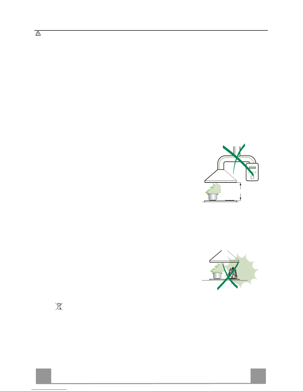
• The minimum safety distance between the cooker top and the extractor
hood is 650 mm (some models can be installed at a lower height, please refer to the paragraphs on working dimensions and installation).
• Check that the mains voltage corresponds to that indicated on the rating
plate fixed to the inside of the hood.
• For Class I appliances, check that the domestic power supply guarantees
adequate earthing.
Connect the extractor to the exhaust flue through a pipe of minimum diame-
ter 120 mm. The route of the flue must be as short as possible.
• Do not connect the extractor hood to exhaust ducts carrying combustion
fumes (boilers, fireplaces, etc.).
• If the extractor is used in conjunction with non-electrical appliances (e.g. gas
burning appliances), a sufficient degree of aeration must be guaranteed in
the room in order to prevent the backflow of exhaust gas. The kitchen must
have an opening communicating directly with the open air in order to
guarantee the entry of clean air.
USE
• The extractor hood has been designed exclusively for domestic use to eliminate kitchen smells.
• Never use the hood for purposes other than for which it has been designed.
• Never leave high naked flames under the hood when it is in operation.
• Adjust the flame intensity to direct it onto the bottom of the pan only, making
sure that it does not engulf the sides.
• Deep fat fryers must be continuously monitored during use: overheated oil
can burst into flames.
• Do not flambè under the range hood; risk of fire
• This appliance is not intended for use by persons (including children) with
reduced physical, sensory or mental capabilities, or lack of experience and
knowledge, unless they have been given supervision or instruction concerning use of the appliance by a person responsible for their safety.
• Children should be supervised to ensure that they do not play with the appliance.
MAINTENANCE
• Switch off or unplug the appliance from the mains supply before carrying out
any maintenance work.
• Clean and/or replace the Filters after the specified time period (Fire hazard).
• Clean the hood using a damp cloth and a neutral liquid detergent.
The symbol on the product or on its packaging indicates that this product may not be treated
as household waste. Instead it shall be handed over to the applicable collection point for the
recycling of electrical and electronic equipment. By ensuring this product is disposed of correctly,
you will help prevent potential negative consequences for the environment and human health,
which could otherwise be caused by inappropriate waste handling of this product. For more
detailed information about recycling of this product, please contact your local city office, your
household waste disposal service or the shop where you purchased the product.
650 mm min.
Page 4
EN
4
4
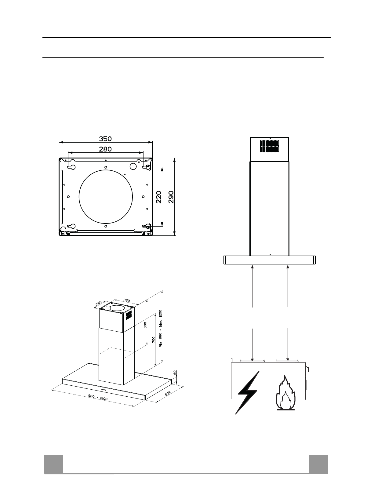
CHARACTERISTICS
Dimensions
Min.
500mm
Min.
650mm
Page 5
EN
5
5
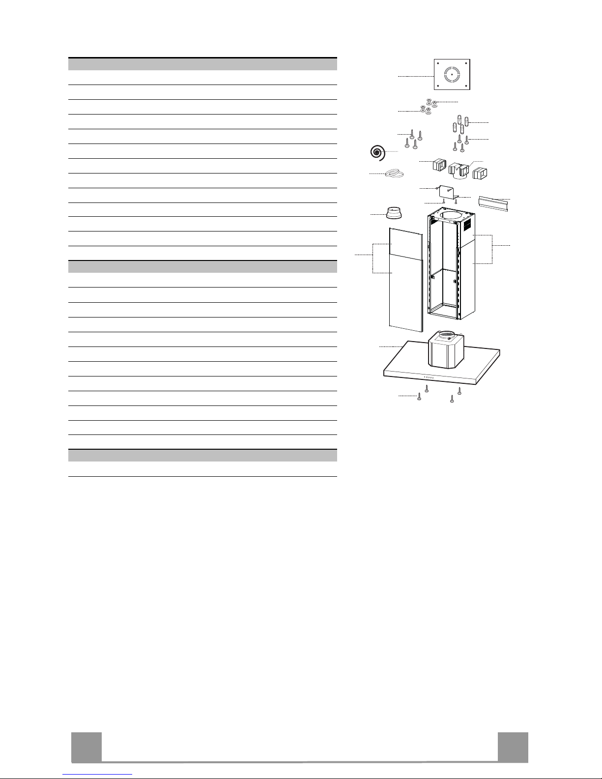
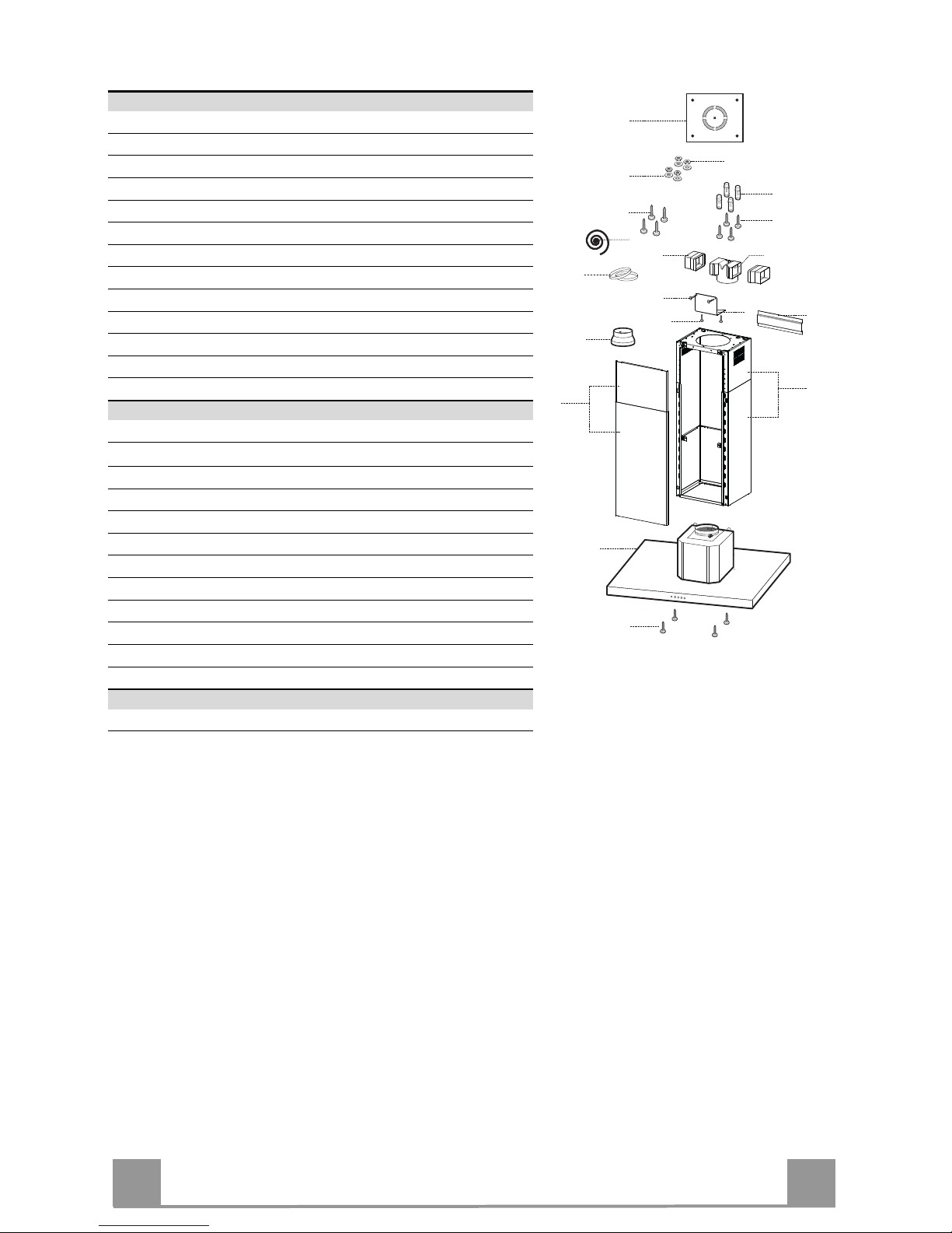
Components
Ref. Q.ty Product Components
1 1 Hood Canopy complete with: Controls, Light, Filters
2 1 Telescopic chimney, made up of:
2.1 1 Upper chimney
2.2 1 Lower chimney
3 1 Telescopic panel, made up of:
3.1 1 Upper panel
3.2 1 Lower panel
9 1 Reduction flange ø 150-120 mm
14.1 1 Air Outlet Connector Extension
15 1 Air Outlet Connector
16 1 Novastick tape
25 Hose clamps (not supplied)
Ref. Q.ty Installation Components
7.3 1 Air outlet connector fixing bracket
7.2
1 Telescopic chimney fixing bracket
11 4 Wall plugs ø 10
12c 2 Screws 2.9 x 6.5
12e 2 Screws 2.9 x 9.5
12f 4 Screws M4 x 80
12g 4 Screws M6 x 80
12h 4 Screws 5.2 x 70
21 1 Drilling template
22 4 Washers ø 6.4
23 4 Nuts M6
Q.ty Documentation
1 Instruction Manual
12h
11
12g
22
23
21
25
1
12f
7.2
12c
12e
9
3
3.1
3.2
2
2.1
2.2
14.1
15
7.3
16
Page 6
EN
6
6
INSTALLATION
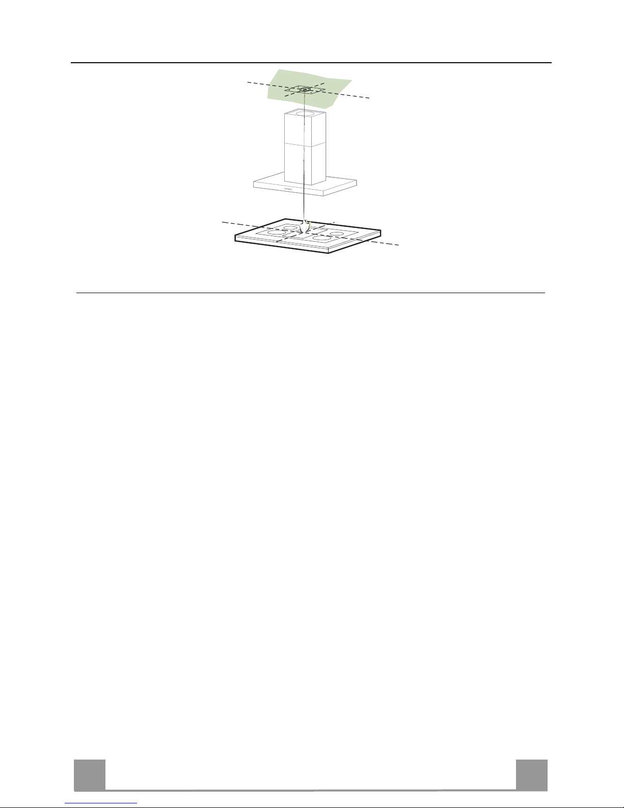
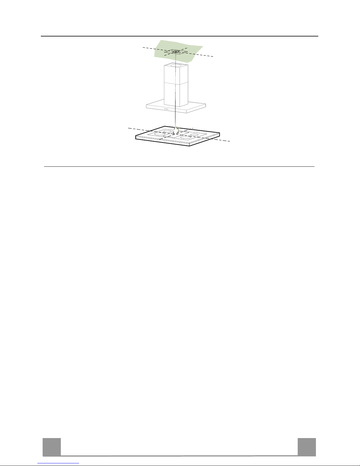
Drilling the Ceiling/shelf and fixing the frame
DRILLING THE CEILING/SHELF
• Use a plumb line to mark the centre of the hob on the ceiling/support shelf.
• Place the drilling template 21 provided on the ceiling/support shelf, making sure that the
template is in the correct position by lining up the axes of the template with those of the hob.
• Mark the centres of the holes in the template.
• Drill the holes at the points marked:
• For concrete ceilings, drill for plugs appropriate to the screw size.
• For hollow brick ceilings with wall thickness of 20 mm: drill ø 10 mm(immediately insert
the Dowels 11 supplied).
• For wooden beam ceilings, drill according to the wood screws used.
• For wooden shelf, drill ø 7 mm.
• For the power supply cable feed, drill ø 10 mm.
• For the air outlet (Ducted Version), drill according to the diameter of the external air ex-
haust duct connection.
• Insert two screws of the following type, crossing them and leaving 4-5 mm from the ceiling:
• For concrete ceilings, use the appropriate plugs for the screw size (not provided).
• for Cavity ceiling with inner space, with wall thickness of approx. 20 mm, Screws 12h,
supplied.
• For wooden beam ceilings, use 4 wood screws (not provided).
• For wooden shelf, use 4 screws 12g with washers 22 and nuts 23, provided.
Page 7
EN
7
7
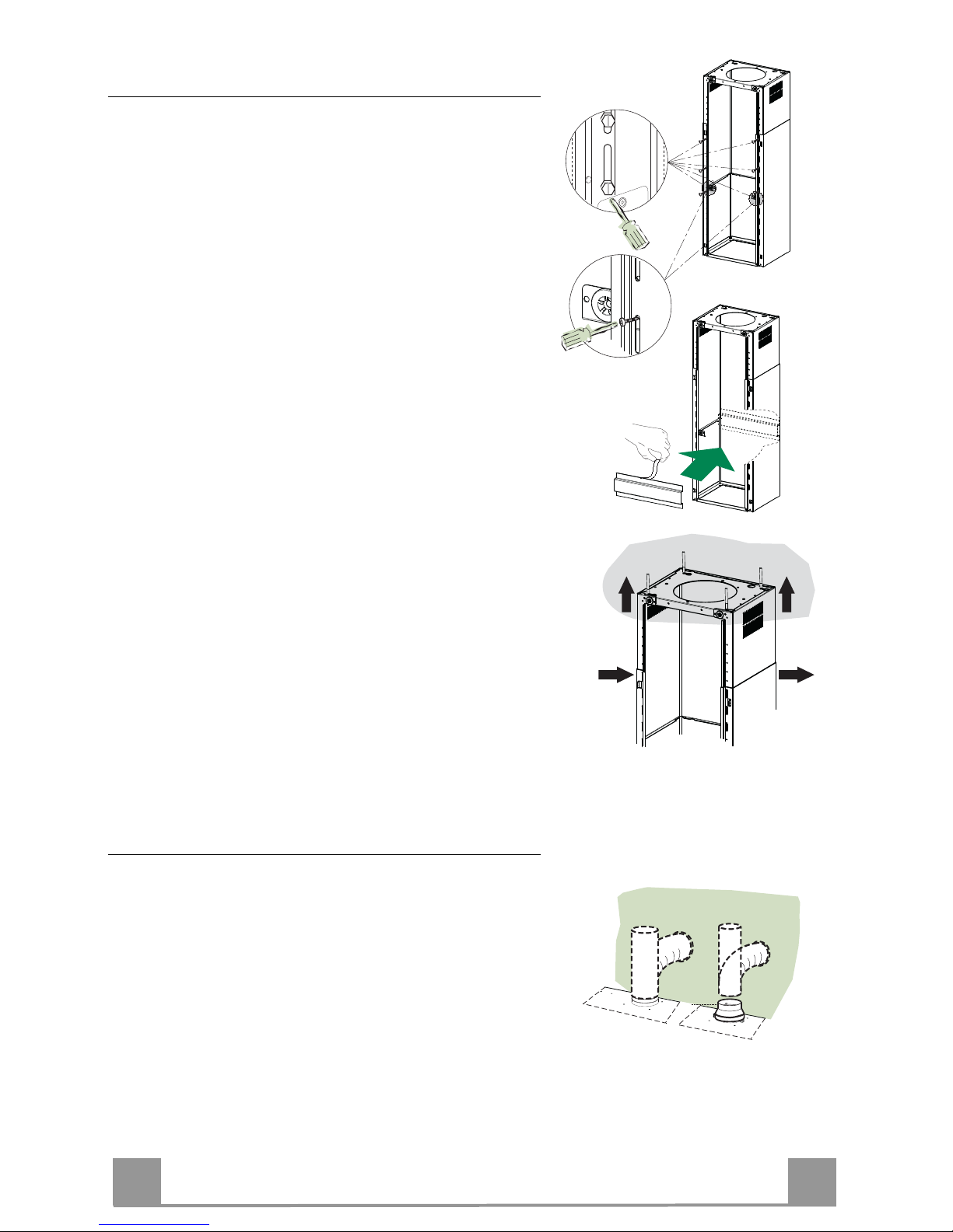
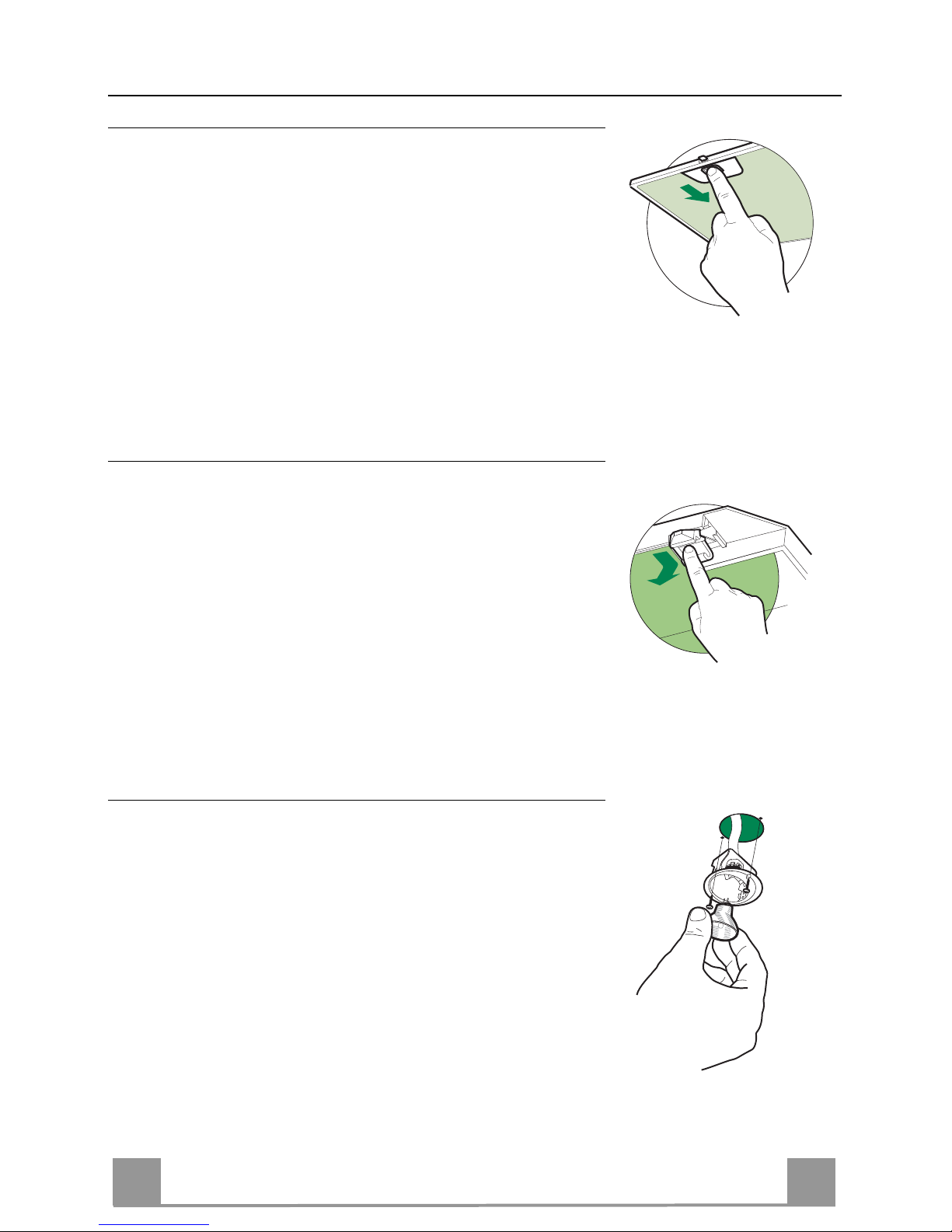
Fixing the Frame/Chimney
Should it be necessary to adjust the height of the frame,
proceed as follows:
• Unfasten the metric screws joining the two opposite
parts that can be seen from the front;
• Adjust the height of the frame as required, then replace the screws removed as above, making sure that
you insert 2 of them close to the panel lock;
• Lift the frame, insert the slots onto the screws and
slide them until they lock;
• Tighten the two screws and insert the other two
screws provided.
• Take the telescopic chimney locking bracket 7.2, remove the film from the double sided adhesive and fix
it inside the frame so as to hold it more firmly.
Before final locking of the screws it is possible to make
small adjustments to the frame, making sure that the
screws do not come out of the adjustment slot.
• The Frame must be securely fastened both due to the
weight of the Hood and the stress caused by occasional sideways pressure on the Appliance when in
position. When fastened, check that the base is stable
even when the Frame is subjected to bending.
• In all cases where the Ceiling is not sufficiently strong
at the point of suspension, the Installation technician
must strengthen it with suitable plates and counterplates, anchored to structurally sound elements.
2
1
2
1
Ducted version air exhaust system Connection
When installing the ducted version, connect the hood to
the chimney using either a flexible or rigid pipe ø 150 or
120 mm, the choice of which is left to the installer.
• To install a ø 120 mm air exhaust connection, insert
the reducer flange 9 on the hood body outlet.
• Fix the pipe using the pipe clamps 25 (not provided).
• Remove any activated charcoal filters.
ø 150
9
ø 120
Page 8
EN
8
8
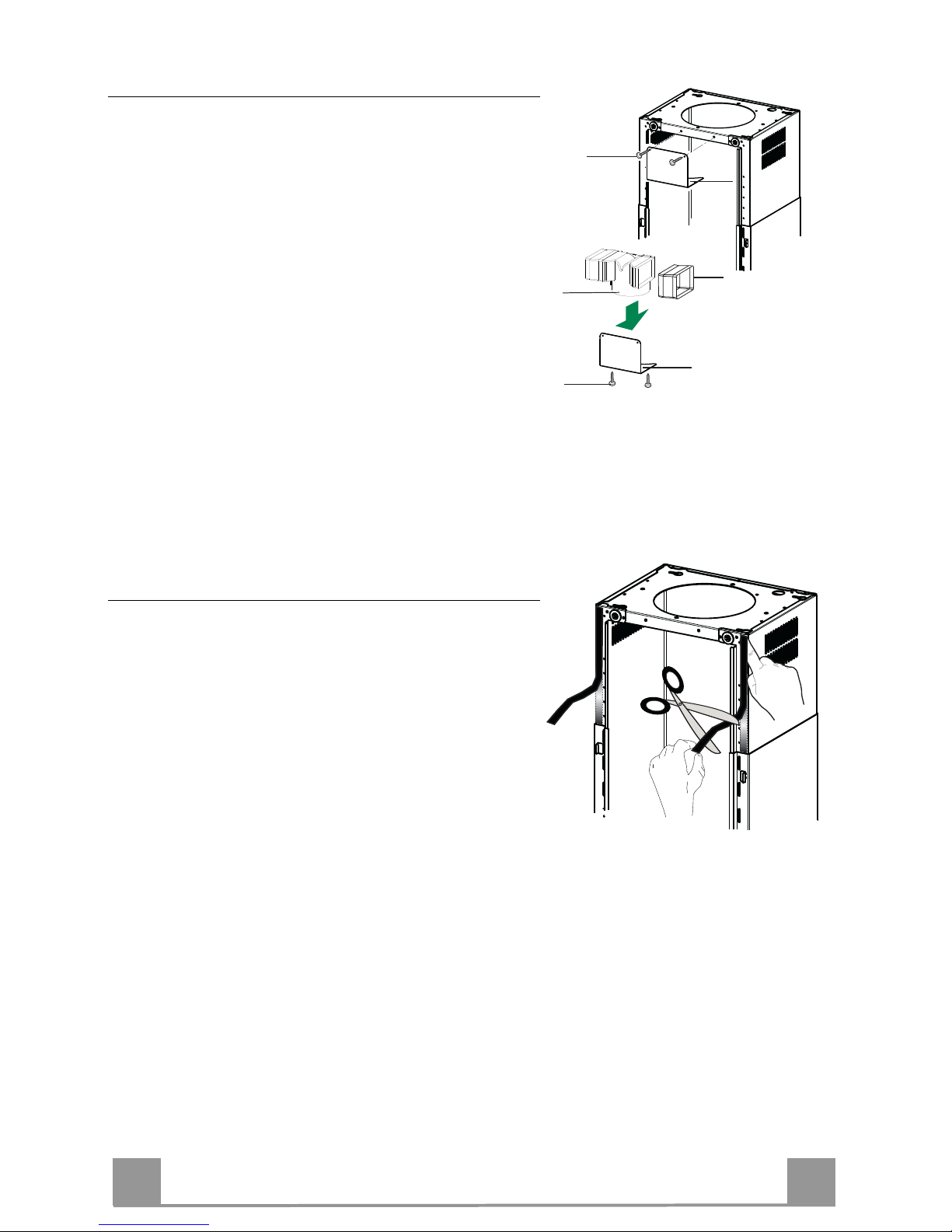
Air outlet – Recirculation Version
• Insert the Connector extensions 14.1 into the side of
the Connector 15.
• Insert the Connector 15 into the Support bracket 7.3
and fix it with the screws.
• Fasten the Support bracket 7.3, fixing it to the upper
part with the Screws.
• Make sure that the Connector extensions outlet 14.1 is
in correspondence with the Chimney openings both
horizontally and vertically.
• Join the Connector 15 to the Hood canopy outlet using
a rigid or flexible pipe ø¸150 mm, selection of which
is at the discretion of the installation technician.
• Make sure that the Activated charcoal odour filter has
been fitted.
7.3
7.3
12c
12e
15
14.1
Application of Novastick Tape
• Apply the Novastick tape 16 to the front edge of the
Upper Chimney from the top part down to the start of
the Lower Chimney.
Page 9
EN
9
9
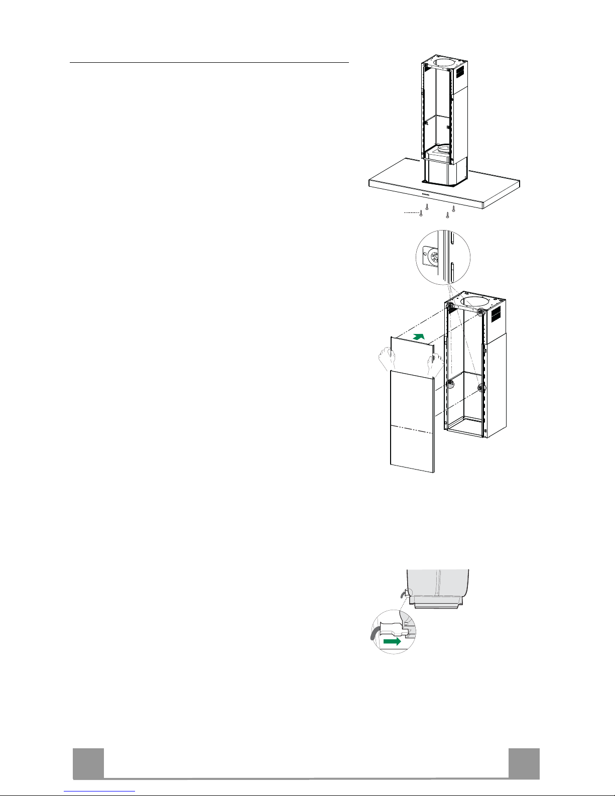
Fitting the Panel and Fixing the Hood Canopy
Before fixing the Hood Canopy to the Frame:
• Remove the Grease filters from the Hood Canopy;
• Remove any Activated charcoal filters.
• Working from below, fix the Hood canopy to the
Frame provided, using the 4 screws 12f (M6 x 10)
provided.
• Then hook the upper part of the Panel 3, adjusted to
size, to the rubber supports in the upper part and in the
lower part of the Frame.
• Slide the lower part of the Panel 3 until its metal tabs
slot into the slots in the frame;
12f
ELECTRICAL CONNECTION
• Connect the hood to the mains through a two-pole
switch having a contact gap of at least 3 mm.
• Remove the grease filters (see paragraph Maintenance) being sure that the connector of the feeding cable is correctly inserted in the socket placed on the
side of the fan.
Page 10
EN
1
10
USE
T2
T1
L
T3
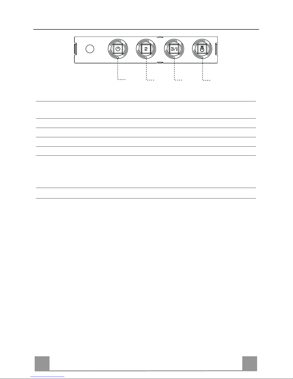
Control panel
BUTTON LED FUNCTIONS
T1 Speed On Turns the Motor on at Speed one.
Turns the Motor off.
T2 Speed On Turns the Motor on at Speed two.
T3 Speed Fixed When pressed briefly, turns the Motor on at Speed three.
Flashing Pressed for 2 Seconds.
Activates Speed four with a timer set to 10 minutes, after
which it returns to the speed that was set previously. Suitable
to deal with maximum levels of cooking fumes.
L Light Turns the Lighting System on and off.
Warning: Button T1 turns the motor off, after first passing to speed one.
Page 11
EN
1
11
MAINTENANCE
Grease filters
CLEANING METAL SELF- SUPPORTING GREASE FILTERS
• The filters must be cleaned every 2 months of operation, or
more frequently for particularly heavy usage, and can be
washed in a dishwasher.
• Remove the filters one at a time by pushing them towards the
back of the group and pulling down at the same time.
• Wash the filters, taking care not to bend them. Allow them to
dry before refitting.
• When refitting the filters, make sure that the handle is visible
on the outside.
Activated charcoal filter (Recirculation version)
REPLACING THE ACTIVATED CHARCOAL FILTER
• The filter is not washable and cannot be regenerated, and must
be replaced approximately every 4 months of operation, or
more frequently for particularly heavy usage.
• Remove the metal grease filters.
• Remove the saturated activated carbon filter by releasing the
fixing hooks.
• Fit the new filter by hooking it into its seating.
• Refit the metal grease filters.
Lighting
LIGHT REPLACEMENT
20 W halogen light.
• Remove the 2 screws fixing the Lighting support, and pull it
out of from the Hood.
• Extract the lamp from the Support.
• Replace with another of the same type, making sure that the
two pins are properly inserted in the lamp holder socket holes.
• Refit the Support, fixing it in place with the two screws removed as above.
Page 12

IT
1
12
CONSIGLI E SUGGERIMENTI
Questo libretto di istruzioni per l'uso è previsto per più versioni dell' apparecchio.
É possibile che siano descritti singoli particolari della dotazione, che non riguardano il Vostro apparecchio.
INSTALLAZIONE
• Il produttore declina qualsiasi responsabilità per danni dovuti ad installazione non
corretta o non conforme alle regole dell’arte.
• La distanza minima di sicurezza tra il Piano di cottura e la Cappa deve essere di
650 mm, (alcuni modelli possono essere installati ad un’altezza inferiore, fare riferimento ai paragrafi ingombro e installazione).
• Verificare che la tensione di rete corrisponda a quella riportata nella targhetta
posta all’interno della Cappa.
• Per Apparecchi in Classe I
a
accertarsi che l’impianto elettrico domestico garanti-
sca un corretto scarico a terra.
• Collegare la Cappa all’uscita dell’aria aspirata con tubazione di diametro pari o
superiore a 120 mm. Il percorso della tubazione deve essere il più breve possibile.
• Non collegare la Cappa a condotti di scarico dei fumi prodotti da combustione
(caldaie, caminetti, ecc.).
• Nel caso in cui nella stanza vengano utilizzati sia la Cappa che apparecchi non
azionati da energia elettrica (ad esempio apparecchi utilizzatori di gas), si deve
provvedere ad una aerazione sufficiente dell’ambiente. Se la cucina ne fosse
sprovvista, praticare un’apertura che comunichi con l’esterno, per garantire il richiamo d’aria pulita.
USO
• La Cappa è stata progettata esclusivamente per uso domestico, per abbattere gli
odori della cucina.
• Non fare mai uso improprio della Cappa.
• Non lasciare fiamme libere a forte intensità sotto la Cappa in funzione.
• Regolare sempre le fiamme in modo da evitare una evidente fuoriuscita laterale
delle stesse rispetto al fondo delle pentole.
• Controllare le friggitrici durante l’uso: l’olio surriscaldato potrebbe infiammarsi.
• Non preparare alimenti flambè sotto la cappa da cucina; pericolo d'incendio.
• Questo apparecchio non deve essere utilizzato da persone (bambini inclusi) con
ridotte capacità psichiche, sensoriali o mentali, oppure da persone senza esperienza e conoscenza, a meno che non siano controllati o istruiti all’uso
dell’apparecchio da persone responsabili della loro sicurezza.
• I bambini devono essere supervisionati per assicurarsi che non giochino con
l’apparecchio.
MANUTENZIONE
• Prima di procedere a qualsiasi operazione di manutenzione, disinserire la Cappa
togliendo la spina elettrica o spegnendo l’interruttore generale.
• Effettuare una scrupolosa e tempestiva manutenzione dei Filtri secondo gli intervalli consigliati (Rischio di incendio).
• Per la pulizia delle superfici della Cappa è sufficiente utilizzare un panno umido e
detersivo liquido neutro.
Il simbolo sul prodotto o sulla confezione indica che il prodotto non deve essere considerato
come un normale rifiuto domestico, ma deve essere portato nel punto di raccolta appropriato per
il riciclaggio di apparecchiature elettriche ed elettroniche. Provvedendo a smaltire questo prodotto in modo appropriato, si contribuisce a evitare potenziali conseguenze negative per l’ambiente
e per la salute, che potrebbero derivare da uno smaltimento inadeguato del prodotto. Per informazioni più dettagliate sul riciclaggio di questo prodotto, contattare l’ufficio comunale, il servizio
locale di smaltimento rifiuti o il negozio in cui è stato acquistato il prodotto.
650 mm min.
Page 13

IT
1
13
CARATTERISTICHE
Ingombro
Min.
500mm
Min.
650mm
Page 14
IT
1
14
Componenti
Rif. Q.tà Componenti di Prodotto
1 1 Corpo Cappa completo di: Comandi, Luce, Filtri
2 1 Camino telescopico formato da:
2.1 1 Camino superiore
2.2 1 Camino inferiore
3 1 Pannello telescopico formato da:
3.1 1 Pannello superiore
3.2 1 Pannello inferiore
9 1 Flangia di riduzione ø 150-120 mm
14.1 1 Prolunga Raccordo Uscita Aria
15 1 Raccordo Uscita Aria
16 1 Nastro Novastick
25 Fascette stringitubo (non incluse)
Rif. Q.tà Componenti di Installazione
7.3 1 Staffa fissaggio raccordo uscita aria
7.2
1 Staffa bloccaggio camino telescopico
11 4 Tasselli ø 10
12c 2 Viti 2,9 x 6,5
12e 2 Viti 2,9 x 9,5
12f 4 Viti M4 x 80
12g 4 Viti M6 x 80
12h 4 Viti 5,2 x 70
21 1 Dima di foratura
22 4 Rondelle ø 6,4
23 4 Dadi M6
Q.tà Documentazione
1 Libretto Istruzioni
12h
11
12g
22
23
21
25
1
12f
7.2
12c
12e
9
3
3.1
3.2
2
2.1
2.2
14.1
15
7.3
16
Page 15
IT
1
15
INSTALLAZIONE
Foratura Soffitto/Mensola e Fissaggio Traliccio
FORATURA SOFFITTO/MENSOLA
• Con l’ausilio di un Filo a piombo riportare sul Soffitto/Mensola di supporto il centro del
Piano di Cottura.
• Appoggiare al Soffitto/Mensola la Dima di Foratura 21 in dotazione, facendo coincidere il
suo centro al centro proiettato e allineando gli assi della Dima agli assi del Piano di Cottura.
• Segnare i centri dei Fori della Dima.
• Forare i punti seguenti:
• Soffitto in Calcestruzzo massiccio: secondo Tasselli per Calcestruzzo impiegati.
• Soffitto in Laterizio a camera d’aria, con spessore resistente di 20 mm: ø 10 mm (inserire
subito i Tasselli 11 in dotazione).
• Soffitto in Travatura di Legno: secondo Viti per Legno impiegate.
• Mensola in Legno: ø 7 mm.
• Passaggio del Cavo elettrico di Alimentazione: ø 10 mm.
• Uscita Aria (Versione Aspirante): secondo diametro del collegamento alla Tubazione di
Evacuazione Esterna.
• Avvitare, incrociandole e lasciando 4-5 mm dal soffitto, due viti:
• per Calcestruzzo massiccio, Tasselli per Calcestruzzo, non in dotazione.
• per Laterizio a camera d’aria, con spessore resistente di 20 mm circa, Viti 12h, in dotazio-
ne.
• per Travatura di legno, Viti per legno, non in dotazione.
• per Mensola in Legno, viti 12g con Rondelle 22 e Dadi 23, in dotazione.
Page 16

IT
1
16
Fissaggio Traliccio/Camino
Nel caso in cui si voglia regolare l’altezza del traliccio procedere
come segue:
• Svitare le viti metriche che uniscono le due parti di fronte visibili frontalmente;
• Regolare l’altezza desiderata del traliccio e riavvitare le viti
precedentemente tolte, avendo l’accortezza di metterne 2 in
prossimità del blocco pannello;
• Sollevare il traliccio, incastrare le asole sulle viti e scorrere
fino a battuta;
• Stringere le due viti e avvitare le altre due in dotazione;
• Prendere la staffa bloccaggio camino telescopico 7.2, togliere
la pellicola del biadesivo e attaccarla internamente al traliccio
in modo da tenerlo più fisso.
Prima di serrare definitivamente le viti è possibile effettuare delle
regolazioni spostando il traliccio facendo attenzione che le viti
non escano dalla sede dell’asola di regolazione.
• Il fissaggio del Traliccio deve essere sicuro in relazione sia al
peso della Cappa sia alle sollecitazioni causate da occasionali
spinte laterali all’Apparecchio montato. A fissaggio avvenuto
verificare quindi che la base sia stabile anche se il Traliccio è
sollecitato a flessione.
• In tutti i casi in cui il Soffitto non fosse sufficientemente robusto sul punto di sospensione, l’Installatore dovrà provvedere a
irrobustirlo con opportune piastre e contropiastre ancorate a
parti strutturalmente resistenti.
2
1
2
1
Connessione Uscita aria Versione Aspirante
Per installazione in Versione Aspirante collegare la Cappa alla
tubazione di uscita per mezzo di un tubo rigido o flessibile di
ø 150 o 120 mm, la cui scelta è lasciata all’installatore.
• Per collegamento con tubo ø 120 mm, inserire la Flangia di
riduzione 9 sull’Uscita del Corpo Cappa.
• Fissare il tubo con adeguate fascette stringitubo 25(non incluse).
• Rimuovere eventuali filtri al carbone attivo.
ø 150
9
ø 120
Page 17

IT
1
17
Uscita aria Versione Filtrante
• Inserire lateralmente le Prolunghe Raccordo 14.1 sul Raccordo
15.
• Inserire il Raccordo 15 nella Staffa di Sostegno 7.3 fissandolo
con le Viti.
• Fissare la Staffa di Sostegno 7.3 fissandola con le Viti alla parte superiore.
• Assicurarsi che l’uscita delle Prolunghe Raccordo 14.1 risulti
in corrispondenza delle bocchette del Camino sia in orizzontale
che in verticale.
• Collegare il Raccordo 15 all’Uscita del Corpo Cappa per mez-
zo di un tubo rigido o flessibile di ø150 mm, la cui scelta è lasciata all'installatore.
• Assicurarsi della presenza del Filtro Antiodore al Carbone atti-
vo.
7.3
7.3
12c
12e
15
14.1
Applicazione Nastro Novastick
• Applicare il nastro Novastick 16 sul bordo frontale del Camino
Superiore dalla parte superiore fino all’inizio del Camino Inferiore.
Page 18

IT
1
18
Montaggio Pannello e Fissaggio Corpo Cappa
Prima di fissare il Corpo Cappa al Traliccio:
• Togliere i Filtri antigrasso dal Corpo Cappa;
• Togliere eventuali Filtri Antiodore al Carbone attivo.
• Fissare quindi dal sotto, con 4Viti 12f (M6 x 10) in dotazione,
il Corpo Cappa al Traliccio predisposto.
• Successivamente agganciare la parte superiore del Pannello
3,regolato a misura, sui supporti di gomma presenti nella parte
superiore del Traliccio e anche in quella inferiore;
• Scorrere la parte inferiore del Pannello 3 finchè le sue linguette
metalliche non si incastrano sulle asole del traliccio;
12f
CONNESSIONE ELETTRICA
• Collegare la Cappa all’Alimentazione di Rete interponendo un
Interruttore bipolare con apertura dei contatti di almeno 3 mm.
• Rimuovere i Filtri antigrasso (vedi par. “Manutenzione”) e assicurarsi che il connettore del Cavo di alimentazione sia correttamente inserito nella presa dell’Aspiratore
Page 19

IT
1
19
USO
T2
T1
L
T3
Quadro comandi
TASTO LED FUNZIONI
T1 Velocità Acceso Accende il Motore alla Prima velocità.
Spegne il Motore.
T2 Velocità Acceso Accende il Motore alla Seconda velocità.
T3 Velocità Fisso Premuto brevemente Accende il Motore alla Terza velocità.
Lampeggiante Premuto per 2 Secondi .
Attiva la Quarta velocità temporizzata a 10 minuti, al termine
dei quali ritorna alla velocità precedentemente impostata. Adatta a fronteggiare le massime emissioni di fumi di cottura.
L Luce Accende e spegne l’Impianto di Illuminazione.
Attenzione: Il tasto T1 spegne il motore passando sempre per la prima velocità.
Page 20

IT
2
20
MANUTENZIONE
Filtri antigrasso
PULIZIA FILTRI ANTIGRASSO METALLICI AUTOPORTANTI
• Sono lavabili anche in lavastoviglie, e necessitano di essere
lavati ogni 2 mesi circa di utilizzo o più frequentemente, per un
uso particolarmente intenso.
• Togliere i Filtri uno alla volta, spingendoli verso la parte posteriore del gruppo e tirando contemporaneamente verso il basso.
• Lavare i Filtri evitando di piegarli, e lasciarli asciugare prima
di rimontarli.
• Rimontarli facendo attenzione a mantenere la maniglia verso la
parte visibile esterna.
Filtro antiodore (Versione Filtrante)
SOSTITUZIONE FILTRO ANTIODORE AL CARBONE ATTIVO
• Non è lavabile e non è rigenerabile, va sostituito almeno ogni 4
mesi o più frequentemente, per un uso particolarmente intenso.
• Togliere i Filtri antigrasso metallici.
• Rimuovere il Filtro antiodore al Carbone attivo saturo, agendo
sugli appositi agganci.
• Montare il nuovo Filtro agganciandolo nella sua sede.
• Rimontare i Filtri antigrasso metallici.
Illuminazione
SOSTITUZIONE LAMPADE
Lampade alogene da 20 W.
• Togliere le due viti che fissano il Supporto illuminazione e sfilarlo dalla Cappa.
• Estrarre la Lampada dal Supporto.
• Sostituirla con una nuova di uguali caratteristiche, facendo attenzione di inserire correttamente i due spinotti nella sede del
Supporto.
• Rimontare il Supporto fissandola con le due Viti precedentemente tolte.
Page 21

FR
2
21
CONSEILS ET SUGGESTIONS
La présente notice d'emploi vaut pour plusieurs versions de l'appareil. Elle peut conte-
nir des descriptions d'accessoires ne figurant pas dans votre appareil.
INSTALLATION
• Le fabricant décline toute responsabilité en cas de dommage dû à une installation non
correcte ou non conforme aux règles de l’art.
• La distance minimale de sécurité entre le plan de cuisson et la hotte doit être de 650
mm au moins (certains modèles peuvent être installés à une hauteur inférieure : se reporter aux paragraphes « Encombrement » et « Installation »).
• Vérifier que la tension du secteur correspond à la valeur qui figure sur la plaquette
apposée à l’intérieur de la hotte.
• Pour les Appareils appartenant à la Ière Classe, veiller à ce que la mise à la terre de
l’installation électrique domestique ait été effectuée conformément aux normes en vigueur.
• Connecter la hotte à la sortie d’air aspiré à l’aide d’une tuyauterie d’un diamètre égal ou
supérieur à 120 mm. Le parcours de la tuyauterie doit être le plus court possible.
• Ne pas connecter la hotte à des conduites d’évacuation de fumées issues d’une combustion tel que (Chaudière, cheminée, etc…).
• Si vous utilisez des appareils qui ne fonctionnent pas à l’électricité dans la pièce ou est
installée la hotte (par exemple: des appareils fonctionnant au gaz), vous devez prévoir
une aération suffisante du milieu. Si la cuisine en est dépourvue, pratiquez une ouverture qui communique avec l’extérieur pour garantir l’infiltration de l’air pur.
UTILISATION
• La hotte a été conçue exclusivement pour l’usage domestique, dans le but d’éliminer
les odeurs de la cuisine.
• Ne jamais utiliser abusivement la hotte.
• Ne pas laisser les flammes libres à forte intensité quand la hotte est en service.
• Toujours régler les flammes de manière à éviter toute sortie latérale de ces dernières
par rapport au fond des marmites.
• Contrôler les friteuses lors de l’utilisation car l’huile surchauffée pourrait s’enflammer.
• Ne pas préparer d’aliments flambés sous la hotte de cuisine : risque d’incendie
• Cet appareil ne doit pas être utilisé par des personnes (y compris les enfants) ayant
des capacités psychiques, sensorielles ou mentales réduites, ni par des personnes
n’ayant pas l’expérience et la connaissance de ce type d’appareils, à moins d'être sous
le contrôle et la formation de personnes responsables de leur sécurité.
• Les enfants doivent être surveillés pour s'assurer qu'ils ne jouent pas avec l'appareil.
ENTRETIEN
• Avant de procéder à toute opération d’entretien, retirer la hotte en retirant la fiche ou en
actionnant l’interrupteur général.
• Effectuer un entretien scrupuleux et en temps dû des Filtres, à la cadence conseillée
(Risque d’incendie).
• Pour le nettoyage des surfaces de la hotte, il suffit d’utiliser un chiffon humide et détersif liquide neutre.
Le symbole sur le produit ou son emballage indique que ce produit ne peut être traité comme
déchet ménager. Il doit plutôt être remis au point de ramassage concerné, se chargeant du recyclage du matériel électrique et électronique. En vous assurant que ce produit est éliminé correctement, vous favorisez la prévention des conséquences négatives pour l’environnement et la santé
humaine qui, sinon, seraient le résultat d’un traitement inapproprié des déchets de ce produit. Pour
obtenir plus de détails sur le recyclage de ce produit, veuillez prendre contact avec le bureau municipal de votre région, votre service d’élimination des déchets ménagers ou le magasin où vous avez
acheté le produit.
650 mm min.
Page 22

FR
2
22
CARACTERISTIQUES
Encombrement
Min.
500mm
Min.
650mm
Page 23

FR
2
23
Composants
Réf. Q.té Composants du produit
1 1 Corps de hotte comprenant : Commandes, Éclairage,
Filtres
2 1 Conduit télescopique constitué de :
2.1 1 Conduit supérieur
2.2 1 Conduit inférieur
3 1 Conduit télescopique constitué de:
3.1 1 Panneau supérieur
3.2 1 Panneau inférieur
9 1 Bride de réduction ø 150 - 120 mm
14.1 1 Rallonge raccord de sortie de l’air
15 1 Raccord de sortie de l’air
16 1 Bande Novastick
25 Colliers serre-tube (non compris)
Réf. Q.té Composants d’installation
7.3 1 Bride de serrage raccord sortie air
7.2
1 Bride de serrage conduit télescopique
11 4 Chevilles ø 10
12c 2 Vis 2,9 x 6,5
12e 2 Vis 2,9 x 9,5
12f 4 Vis M4 x 80
12g 4 Vis M6 x 80
12h 4 Vis 5,2 x 70
21 1 Gabarit de perçage
22 4 Rondelles ø 6,4
23 4 Écrous M6
Q.té Documentation
1 Manuel d’instructions
12h
11
12g
22
23
21
25
1
12f
7.2
12c
12e
9
3
3.1
3.2
2
2.1
2.2
14.1
15
7.3
16
Page 24

FR
2
24
INSTALLATION
Perçage Plafond/Étagère et Fixation Treillis
PERÇAGE PLAFOND/ETAGERE
• À l’aide d’un Fil à plomb, reporter sur le Plafond/Étagère de support le centre du Plan de
Cuisson.
• Poser contre le Plafond/Étagère le Gabarit de Perçage 21 fourni avec l’appareil, en faisant
coïncider son centre avec le centre projeté et en alignant les axes du Gabarit avec les axes du
Plan de Cuisson.
• Marquer les centres des Trous du Gabarit.
• Percer les trous qui ont été marqués:
• Plafond en Béton massif: en fonction des Goujons pour Béton utilisés.
• Plafond en Briques avec chambre à air, avec épaisseur résistante de 20 mm: ø 10 mm (in-
sérer immédiatement les Chevilles 11 fournies avec l’appareil).
• Plafond en Poutrage en Bois: en fonction des Vis à Bois utilisées.
• Étagère en Bois: ø 7 mm.
• Passage du Câble électrique d’Alimentation: ø 10 mm.
• Sortie Air (Version Aspirante): en fonction du diamètre de la connexion avec les Tuyaux
d’Évacuation Externe.
• Visser deux vis en les croisant et en laissant 4-5 mm. de distance par rapport au plafond:
• pour le Béton massif, des Goujons pour Béton, non fournis avec l’appareil.
• pour Briques percées, ayant une épaisseur résistante de 20 mm. environ, utiliser les Vis
12h, fournies avec l'appareil.
• pour le Poutrage en bois, 4 Vis à bois, non fournies avec l’appareil.
• pour l’Étagère en Bois, 4 Vis 12g avec Rondelles 22 et Écrous 23, fournis avec l’appareil.
Page 25

FR
2
25
Fixation Treillis/Conduit
Au cas où l’on souhaiterait régler la hauteur du treillis, suivre la
marche ci-dessous :
• Desserrer les vis métriques d’assemblage des deux parties frontales visibles par la partie avant ;
• Régler la hauteur désirée du treillis et resserrer les vis précédemment retirées, en ayant soin d’en placer 2 à proximité du
blocage du panneau ;
• Soulever le treillis, emboîter les fentes sur les vis et faire coulisser jusqu'en butée ;
• Serrer les deux vis et visser les deux autres vis fournies.
• Saisir la bride de serrage du conduit télescopique 7.2, retirer le
film biadhésif et le coller intérieurement au treillis de manière
à ce qu’il soit plus solide.
Avant de serrer définitivement les vis, on pourra effectuer des
réglages en déplaçant le treillis, en veillant à ce que les vis ne sortent pas du logement de la fente de réglage.
• La fixation du treillis doit être ferme tant par rapport au poids
de la hotte qu’en ce qui concerne les contraintes résultant des
poussées latérales occasionnelles subies par l’appareil une fois
monté. Une fois fixé, vérifier que la base est stable même si le
treillis fait l'objet d’efforts en flexion.
• Dans tous les cas où le plafond n'est pas suffisamment robuste
au point de suspension, le monteur devra prendre des mesures
pour le renforcer avec des plaques et contreplaques appropriées, ancrées sur des parties structurellement résistantes.
2
1
2
1
SORTIE AIR VERSION ASPIRANTE
En cas d’installation en version aspirante, brancher la hotte à la
tuyauterie de sortie via un tube rigide ou flexible de ø 150 ou 120
mm, au choix de l’installateur.
• En cas de branchement avec un tube de ø120 mm, insérer le
flasque de réduction 9 sur la sortie du corps de la hotte.
• Fixer le tuyau à l’aide des Colliers de serrage serre-tube 25 (ne
fournis pas).
• Retirer les éventuels filtres anti-odeur au charbon actif.
ø 150
9
ø 120
Page 26

FR
2
26
Sortie de l’air version filtrante
• Monter latéralement les rallonges du raccord 14.1 sur le raccord 15 ;
• Placer le raccord 15 dans l’étrier de soutien 7.3 en le fixant
avec les vis ;
• Fixer l’étrier de soutien 7.3 en le fixant avec les vis à la partie
supérieure.
• S’assurer que la sortie des rallonges du raccord 14.1 se trouve
en face des ouvertures du conduit, aussi bien horizontalement
que verticalement ;
• Raccorder le raccord 15 à la sortie du corps de hotte au moyen
d’un tuyau rigide ou flexible de 150 mm de diamètre, au choix
de l'installateur ;
• S’assurer de la présence du filtre anti-odeur au charbon actif.
7.3
7.3
12c
12e
15
14.1
Application Bande Novastick
• Appliquer la bande Novastick 16 sur le bord frontal du conduit
supérieur en partant du haut jusqu’au début du conduit inférieur.
Page 27

FR
2
27
Montage du panneau et fixation du corps de hotte
Avant de fixer le corps de hotte au treillis :
• Retirer les filtres à graisse du corps de hotte.
• Retirer les éventuels filtres anti-odeur au charbon actif.
• En passant par-dessous, fixer ensuite le corps de hotte au treillis, avec les 4 vis 12f fournies (M6 x 10).
• Accrocher ensuite la partie supérieure du panneau 3, réglé sur
mesure, sur les supports en caoutchouc présents dans la partie
supérieure du treillis et également dans celle inférieure ;
• Faire coulisser la partie inférieure du panneau 3 jusqu’à ce que
ses languettes métalliques s’emboîtent dans les trous du treillis ;
12f
BRANCHEMENT ELECTRIQUE
• Brancher la hotte sur le secteur en interposant un interrupteur
bipolaire avec ouverture des contacts d’au moins 3 mm.
• Enlever les filtres à graisse (voir § "Entretien") et s'assurer que
le connecteur du câble d'alimentation soit bien branché dans la
prise du diffuseur.
Page 28

FR
2
28
UTILISATION
T2
T1
L
T3
Tableau des commandes
TOUCHE VOYANT FONCTIONS
T1 Vitesse Allumé Démarre le moteur en première vitesse.
Coupe le moteur.
T2 Vitesse Allumé Démarre le moteur en deuxième vitesse.
T3 Vitesse Fixe Appuyée brièvement, démarre le moteur en troisième vitesse.
Clignotant Appuyée pendant 2 secondes.
Démarre la quatrième vitesse avec une temporisation de 10 mi-
nutes, après lesquelles le moteur retourne à la vitesse précédemment programmée. Fonction indiquée pour faire face aux pointes
d’émission de fumées de cuisson.
L Lumière Branche et débranche l’éclairage.
Attention : La touche T1 coupe le moteur en passant toujours par la première vitesse.
Page 29

FR
2
29
ENTRETIEN
Filtres anti-graisse
NETTOYAGE FILTRES ANTI-GRAISSE METALLIQUES AUTOPORTEURS
• Lavables au lave-vaisselle, ils doivent être lavés environ tous
les 2 mois d’emploi ou plus fréquemment en cas d’emploi particulièrement intense.
• Retirer les filtres l’un aprés l’autre, en les poussant vers la partie arrière du groupe et en tirant simultanément vers le bas.
• Laver les filtres en évitant de les plier et les laisser sécher avant
de les remonter.
• Remonter les filtres en veillant à ce que la poignée reste vers la
partie visible externe
Filtre anti-odeur (Version filtrante)
REMPLACEMENT FILTRE AU CHARBON ACTIF
• Ni lavable, ni régénérable, le remplacer au moins tous les 4
mois d’emploi ou plus fréquemment en cas d’emploi particulièrement intense.
• Retirer les filtres anti-graisse métalliques.
• Retirer le filtre anti-odeur au charbon actif colmaté, en agissant
sur les crochets prévus à cet effet.
• Monter le nouveau filtre anti-odeur au charbon actif.
• Remonter les filtres anti-graisse métalliques.
Eclairage
REMPLACEMENT LAMPES
Lampe halogène de 20 W.
• Retirer les 2 Vis qui fixent le Support éclairage et ôter ce dernier de la Hotte.
• Extraire la Lampe du Support.
• Remplacer par une nouvelle lampe possédant les mêmes caractéristiques, en veillant à ce que les deux fiches soient correctement insérées dans le logement de la Douille.
• Remonter le Support en le fixant à l’aide des deux Vis précédemment retirées.
Page 30

DE
3
30
EMPFEHLUNGEN UND HINWEISE
Diese Gebrauchsanleitung gilt für mehrere Geräte-Ausführungen. Es ist möglich, dass
einzelne Ausstattungsmerkmale beschrieben sind, die nicht auf Ihr Gerät zutreffen.
MONTAGE
• Der Hersteller haftet nicht für Schäden, die auf eine fehlerhafte und unsachgemäße Montage zurückzuführen sind.
• Der minimale Sicherheitsabstand zwischen Kochmulde und Haube muss 650 mm betragen (einige Modelle können an einer geringeren Höhe installiert werden, beziehen Sie sich
dazu auf den Absatz Raumbedarf und Installation).
• Prüfen, ob die Netzspannung mit dem Wert auf dem im Haubeninneren angebrachten Schild übereinstimmt.
• Bei Geräten der Klasse I ist sicherzustellen, dass die elektrische Anlage des Wohnhauses
über eine vorschriftsmäßige Erdung verfügt.
• Das Anschlussrohr der Haube zur Luftaustrittsöffnung muss einen Durchmesser von 120
mm oder darüber aufweisen. Der Rohrverlauf muss so kurz wie möglich sein.
• Die Haube darf an keine Entlüftungsschächte angeschlossen werden, in die Verbrennungsgase (Heizkessel, Kamine usw.) geleitet werden.
• Werden im Raum außer der Dunstabzugshaube andere, nicht elektrisch betriebene (z.B.
gasbetriebene) Geräte verwendet, muss für eine ausreichende Belüftung gesorgt werden.
Sollte die Küche diesbezüglich nicht entsprechen, ist an einer Aussenwand eine Öffnung
anzubringen, die Frischluftzufuhr gewährleistet.
BEDIENUNG
• Die Dunstabzugshaube ist ausschließlich zum Einsatz im privaten Haushalt und zur
Beseitigung von Küchengerüchen vorgesehen.
• Unsachgemäßer Einsatz der Haube ist zu unterlassen.
• Große Flammen bei eingeschalteter Haube niemals unbedeckt lassen.
Achtung! Große Flammen bei eingeschalteter Haube niemals unbedeckt lassen.
• Die Intensivität der Flamme ist so zu regulieren, dass sie den Topfboden nicht überragt.
Achtung! Frittiergeräte müssen während des Gebrauchs stets beaufsichtigt wer-
den: Überhitztes Öl kann sich entzünden.
• Frittiergeräte müssen während des Gebrauchs stets beaufsichtigt werden: überhitztes Öl
kann sich entzünden.
• Keine flambierten Speisen unter der Abzugshaube zubereiten: Brandgefahr.
• Dieses Gerät darf nicht von Personen, auch Kindern, mit verminderten psychischen, sensorischen und geistigern Fähigkeiten, oder von Personen ohne Erfahrung und Kenntnisse
benutzt werden, sofern sie nicht von für ihre Sicherheit verantwortlichen Personen beaufsichtigt und beim Gebrauch des Geräts angeleitet werden.
• Kinder dürfen sich nicht unbeaufsichtigt in der Nähe des Geräts aufhalten und auf keinen
Fall mit dem Gerät spielen.
WARTUNG
• Bevor Wartungsarbeiten durchgeführt werden, muss die Stromzufuhr zur Haube unterbrochen werden, indem der Stecker gezogen oder der Hauptschalter abgeschaltet wird.
• Bei der Filterwartung müssen die vom Hersteller empfohlenen Zeiträume zum Austauschen
der Filter genauestens eingehalten werden (Brandgefahr).
• Zur Reinigung der Haubenflächen Wir empfehlen ein feuchtes Tuch und ein mildes Flüssigreinigungsmittel.
• Bitte keine Reinigungsmittel mit Scheuermittel verwenden. Die Oberfläche wird damit
verkratzt.
Das Symbol auf dem Produkt oder seiner Verpackung weist darauf hin, dass dieses Produkt nicht als
normaler Haushaltsabfall zu behandeln ist, sondern an einem Sammelpunkt für das Recycling von elektrischen und elektronischen Geräten abgegeben werden muss. Durch Ihren Beitrag zum korrekten Entsorgen
dieses Produkts schützen Sie die Umwelt und die Gesundheit Ihrer Mitmenschen. Umwelt und Gesundheit
werden durch falsches Entsorgen gefährdet. Weitere Informationen über das Recycling dieses Produkts
erhalten Sie von Ihrem Rathaus, Ihrer Müllabfuhr oder dem Geschäft, in dem Sie das Produkt gekauft haben.
650 mm min.
Page 31

DE
3
31
CHARAKTERISTIKEN
Platzbedarf
Min.
500mm
Min.
650mm
Page 32

DE
3
32
Komponenten
BezugMenge Produktkomponenten
1 1 Haubenkörper, komplett mit: Bedienelemente, Beleuch-
tung, Filter
2 1 Teleskopkamin, bestehend aus:
2.1 1 Oberer Kaminteil
2.2 1 Unterer Kaminteil
3 1 Teleskoppaneel, bestehend aus:
3.1 1 Oberes Paneel
3.2 1 Unteres Paneel
9 1 Reduzierflansch ø 150-120 mm
14.1 1 Anschlussverlängerung Luftauslass
15 1 Anschluss Luftauslass
16 1 Novastick-Band
25 Rohrschellen (nicht enthalten)
BezugMenge Installationskomponenten
7.3 1 Befestigungswinkel Anschluss Luftauslass
7.2
1 Befestigungswinkel Teleskopkamin
11 4 Dübel ø 10 mm
12c 2 Schrauben 2,9 x 6,5
12e 2 Schrauben 2,9 x 9,5
12f 4 Schrauben M4 x 80
12g 4 Schrauben M6 x 80
12h 4 Schrauben 5,2 x 70
21 1 Bohrschablone
22 4 Unterlegscheiben ø 6,4
23 4 Muttern M6
Menge Dokumentation
1 Betriebsanleitung
12h
11
12g
22
23
21
25
1
12f
7.2
12c
12e
9
3
3.1
3.2
2
2.1
2.2
14.1
15
7.3
16
Page 33

DE
3
33
MONTAGE
Bohren der Decke/Trägerplatte und Montage des Teleskopgerüsts
Achtung: Bitte beachten Sie bei der Montage das Gewicht der kompletten Haube. Die Tragfä-
higkeit der Decke oder alternativ der Trägerplatte für diese Zugbelastung muss vor der Montage geprüft und gegebenenfalls durch die Anbringung von geeigneten Befestigungs- oder
Stabilisierungselementen hergestellt werden. Kann eine hinreichende Tragfähigkeit nicht sichergestellt werden, ist von einer Montage abzusehen.
BOHREN DER DECKE/TRAGERPLATTE
• Mit Hilfe eines Lots den Kochmulden-Mittelpunkt an der Decke oder Trägerplatte ermitteln
und kennzeichnen.
• Die mitgelieferte Bohrschablone 21 so auf die Decke/Trägerplatte legen, dass die Schablo-
nenmitte mit dem gekennzeichneten Mittelpunkt übereinstimmt und die Schablonenseiten
auf die Seiten der Kochmulde ausrichten.
• Die Mitte der Schablonenbohrungen kennzeichnen.
• Die gekennzeichneten Punkte bohren:
• Massivbeton-Decke: je nach verwendeten Beton-Dübeln.
• Decke aus Hohlkammer-Ziegeln mit 20 mm Wandungsstärke: ø 10 mm (sofort die mitge-
lieferten Dübel 11 einfügen).
• Holzbalkendecke: je nach verwendeten Holzschrauben.
• Holz-Trägerplatte: ø 7 mm.
• Durchgang für das Speisekabel: ø 10 mm.
• Luftaustritt (Abluftversion): je nach Durchmesser des Anschlussrohres für die Luftablei-
tung.
• Zwei sich gegenüberliegende Schrauben festziehen und 4-5 mm Freiraum zur Decke belassen:
• bei Massiv-Betondecken mit speziellen Betondübeln, die nicht mitgeliefert werden;
• für Hohlkammer-Ziegeln mit ca. 20 mm Wandungsstärke die mitgelieferten Schrauben
12h verwenden;
• bei Holzbalken-Decken mit 4 Holzschrauben, die nicht mitgeliefert werden;
• bei Holz-Trägerplatten mit 4 Schrauben 12g, Unterlegscheiben 22 und Schraubenmuttern
23, die im Lieferumfang enthalten sind.
Page 34

DE
3
34
Fixierung von Gitter/Kamin
Falls die Höhe des Gitters verändert werden soll, wie folgt vorgehen:
• Die metrischen Schrauben lösen, welche die beiden frontal
sichtbaren Frontteile verbinden.
• Die Höhe des Gitters nach Wunsch regulieren und die zuvor
ausgebauten Schrauben wieder einschrauben, wobei 2 Schrauben in der Nähe der Paneelsperre angebracht werden sollen.
• Das Gitter anheben, die Langlöcher an den Schrauben einhaken und bis zum Anschlag gleiten lassen;
• Die beiden Schrauben festziehen und die beiden mitgelieferten
Schrauben einschrauben;
• Den Befestigungswinkel des Teleskopkamins 7.2 zur Hand
nehmen, die Schutzfolie des zweiseitigen Klebebands abziehen
und dieses zur Verstärkung im Innern des Gitters anbringen.
Bevor die Schrauben endgültig festgeschraubt werden, kann
durch Verschieben des Gitters reguliert werden. Dabei darauf
achten, dass die Schrauben nicht aus dem Sitz der Einstelllangschrauben fallen.
• Das Gitter muss entsprechend dem Gewicht der Haube und den
Belastungen durch seitliche Stoßeinwirkungen auf das installierte Gerät sicher befestigt werden. Nach dem Befestigen also
kontrollieren, ob die Basis stabil bleibt, auch wenn das Gitter
Biegebelastungen ausgesetzt ist.
• In allen Fällen, in denen die Decke am Aufhängepunkt nicht
robust genug sein sollte, muss der Installateur sie durch Platten
und Konterplatten verstärken, die an stabilen Strukturteilen
verankert werden.
2
1
2
1
Anschluss in Abluftversion
Bei Abluftbetrieb kann die Haube vom Installateur wahlweise
mittels Rohr oder Schlauch (ø 150 oder 120 mm) an die Außenrohrleitung angeschlossen werden.
• Bei Verwendung eines Anschlussrohres ø 120 den Reduzierflansch 9 am Haubenaustritt anbringen.
• Das Rohr mit den Rohrschellen 25 fixieren (nicht mitgeliefert).
• Eventuell vorhandene Aktivkohlefilter entnehmen.
Achtung! Alle Querschnittänderungen oder Richtungsände-
rungen des Abluftkanals reduzieren die Leistung der Haube.
ø 150
9
ø 120
Page 35

DE
3
35
Luftaustritt bei der Filterversion
• Die Anschlussverlängerungen 14.1 seitlich am Anschluss 15
einsetzen.
• Den Anschluss 15 am Haltewinkel 7.3 einsetzen und mit den
Schrauben fixieren.
• Den Haltewinkel 7.3 mit den Schrauben an der Oberseite be-
festigen.
• Sicherstellen, dass sich der Austritt der Anschlussverlängerungen 14.1 sowohl waagrecht als auch senkrecht auf Höhe der
Öffnungen des Kamins befindet.
• Den Anschluss 15 mittels eines starren oder flexiblen Rohrs
mit ø150 mm, das vom Installateur ausgewählt wird, an den
Austritt des Haubenkörpers anschließen.
• Sicherstellen, dass der Aktivkohlefilter zur Geruchsbindung
vorhanden ist.
7.3
7.3
12c
12e
15
14.1
Anbringen des Novastick-Bands
• Das Novastick-Band 16 an der Frontkante des oberen Kamin-
teils von oben bis zum Anfang des unteren Kaminteils anbringen.
Page 36

DE
3
36
Montage des Paneels und Befestigung des Haubenkörpers
Vor dem Befestigen des Haubenkörpers am Gitter:
• Die Fettfilter aus dem Haubenkörper nehmen.
• Die eventuell vorhandenen Aktivkohlefilter ausbauen.
• Dann den Haubenkörper mit den mitgelieferten 4 Schrauben
12f (M6 x 10) von unten am vorbereiteten Gitter befestigen.
• Danach die Oberkante des nach Maß regulierten Paneels 3 an
den Gummihalterungen an der Ober- und Unterseite des Gitters
einhängen;
• Die Unterkante des Paneels 3 so verschieben, dass die Metalllaschen in die Ösen des Gitters;
12f
Elektroanschluss
Vor der Installation die Netzspannung durch herausdrehen der
Sicherung oder ausschalten des Hauptschalters stromlos machen.
• Bei Anschluss der Haube an das Stromnetz muss ein
zweipoliger Schalter mit einem Öffnungsweg von
mindestens 3 mm zwischengeschaltet werden.
• Entfernen Sie die Fettfilter (s. Abschnitt „Wartung“) und
versichern Sie sich, daß die Kabelverbindung in die Steckdose des Gebläses einwandfrei eingesteckt wird.
Achtung: Das Gerät nur an die Netzspannung die im Typen-
schild angegeben ist anschließen.
Page 37

DE
3
37
BEDIENUNG
T2
T1
L
T3
Schalttafel
TASTE LED FUNKTIONEN
T1 Betriebsgeschwindigkeit Eingeschaltet Schaltet den Motor bei der ersten
Betriebsgeschwindigkeit ein.
Stellt den Motor ab.
T2 Betriebsgeschwindigkeit Eingeschaltet Schaltet den Motor bei der zweiten
Betriebsgeschwindigkeit ein.
T3 Betriebsgeschwindigkeit Bleibend Schaltet den Motor bei der dritten
Betriebsgeschwindigkeit ein.
Blinkend Bei 2 Sekunden langem Drücken:
Aktiviert die auf 10 Minuten geregelte vierte
Betriebsgeschwindigkeit, nach deren Ablauf
zu der zuvor eingestellten Geschwindigkeit
zurückgekehrt wird. Für die Beseitigung von
sehr intensiven Kochdünsten geeignet.
L Licht Schaltet die Beleuchtung ein und aus.
Achtung: Mit der Taste T1 wird von der ersten Betriebsgeschwindigkeit aus der Motor
abgestellt.
Page 38

DE
3
38
WARTUNG
Fettfilter
SELBSTTRAGENDER METALLFETTFILTER REINIGUNG
• Sie müssen nach 2-monatigem Betrieb bzw. bei starkem Einsatz auch häufiger gereinigt werden, was im Geschirrspüler
möglich ist.
• Die Filter nacheinander aushaken, indem sie auf die Rückseite
der Gruppe geschoben und gleichzeitig nach unten gezogen
werden.
• Die Filter reinigen (darauf achten, sie nicht zu verbiegen) und
vor der Remontage trocknen lassen.
• Bei der Remontage ist darauf zu achten, dass sich der Griff auf
der sichtbaren Außenseite befindet.
Geruchsfilter (Umluftversion)
AUSTAUSCHEN DER AKTIVKOHLE FILTER
• Dieser Filter kann weder gewaschen noch wiederverwendet
werden und ist alle 4 Betriebsmonate bzw. bei starkem Einsatz
auch häufiger auszutauschen.
• Die Metallfettfilter entfernen.
• Den gesättigten Aktivkohle-Geruchsfilter aushaken.
• Den neuen Filter in seinem Sitz einhaken.
• Die Metallfettfilter wieder montieren.
Beleuchtung
AUSWECHSELN DER LAMPEN
Halogenlampe 20 W
• Vor dem Auswechseln der Lampen, die beiden Schrauben der
Lampenhalterung loesen und die Lampenhalterung aus der
Dunstabzugshaube ziehen.
• Die Lampe aus der Halterung nehmen.
• Die Lampe durch eine gleichwertige ersetzen und bei der Remontage darauf achten, daß die beiden Steckerstifte vorschriftsmäßig in die Lampenfassung eingeführt werden.
• Die Lampenhalterung wieder montieren, indem die beiden zuvor entfernten Schrauben wieder angezogen werden.
Page 39

TR
3
39
TAVSIYELER VE ÖNERILER
Bu kullanma talimatι birden fazla cihaz modeli için geçerlidir.
Cihazιnιza uymayan bazι donanιm özellikleri tarif edilmiş olabilir.
MONTAJ
• Yalnιş veya eksik montajdan doğan herhangi bir zararιn sorumluluğu üreticiye
ait değildir.
• Davlumbaz ile pişirici cihazιn ocak kιsmι arasιndaki minimum güvenlik mesafesi 650 mm.dir (bazı modeller daha alçak seviyede bir yüksekliğe kurulabilir,
hacim ve kurulum ile ilgili paragraflara bakınız).
• Besleme voltajιnιn, davlumbaz içerisine yerleştirilen bilgi etiketinde belirtilenle
aynι olup olmadιğιnι kontrol edin.
• Sιnιf I elektrikli aletleri için, güç kaynağιnιn yeterli topraklamayι sağlayιp
sağlamadιğιnι kontrol edin. Minimum 120 mm çapιnda bir boru yoluyla
davlumbazι çιkιş bacasιna bağlayιn. Baca bağlant
ιsι mümkün oldu- ğunca
kιsa olmalιdιr.
• Davlumbaz borusunu yanιcι duman taşιyan baca deliğine (buhar kazanι, şö-
mine, vb.) bağlamayιn.
• Davlumbazιn elektrikle çalιşmayan aletlerle (örneğin; gazlι cihazlar) bağιntιlι
olarak kullanιlmamasι halinde çιkιş gazιnιn geri tepmesini önlemek amacιyla
odada yeterli bir havalandιrma sağlanmalιdιr. Temiz hava girişini temin etmek
için mutfakta doğrudan dιşarιya açιlan bir açιklιk bulunmalιdιr.
KULLANIM
• Davlumbaz mutfaktaki kokularιn emilmesi amacιyla evlerde kullanιm için
tasarlanmιştι
r.Ticari ve endüstriyel amaçlar için kullanmayιnιz.
• Davlumbazι tasarlandιğι amaçlarιn dιşιnda kesinlikle kullanmayιnιz.
• Davlumbaz çalιşιrken altιnda kesinlikle yüksek çιplak ateş bιrakmayιn.
• Alev yoğunluğunu doğrudan tencerenin altιnda kalacak şekilde ayarlayιn,
kenarlarιnι sarmadιğιndan emin olun.
• Yağda kιzartma tavalarιnι kullanιrken sürekli olarak takip edin: fazla ιsιnan yağ
tutuşabilir.
• Kapağın altında kıvılcımdan kaçının, yangın riski
• Bu alet, güvenliklerinden sorumlu kişiler tarafından kontrol edilmedikleri veya
eğitilmedikleri sürece; fiziksel, duyumsal ve zihinsel kapasitesinde kısı
tlama
olan (çocuklar dahil) veya aleti kullanma tecrübesi ve bilgisi olmayan kişiler tarafından kullanılamaz.
• Bebeklerin, aletle oynamadıklarından emin olmak için kontrol edilmeli gerekir.
BAKIM
• Herhangi bir bakιm işlemini gerçekleştirmeden önce davlumbazι kapatιn veya
fişini çιkarιn.
• Filtreleri belirtilen zamanlarda temizleyin ve / veya değiştirin(Yangın riski).
• Cihazι nemli bir bez ve nötr bir sιvι deterjan kullanarak temizleyin.
Ürün veya paketi üzerindeki sembolü, bu ürünün normal bir evsel atık olarak görülmemesi
ve bu tip elektrikli veya elektronik cihazların atıldığı dönüşümlü toplama noktalarına terkedilmesi
gerektiğine işaret eder. Bu ürünü gerektiği gibi elimine etme kurallarına uyarsanız çevre ve insan
sağlığı üzerindeki olumsuz etkilerini bertaraf etmeye katkı sağlamış olursunuz. Bu ürünün geri
dönüşüm koşulları hakkında daha ayrıntılı bilgi için hudutları içinde bulunduğunuz belediyenin
ilgili diaresine, atık yoketme servisine veya ürünün satıcısına danışınız.
650 mm min.
Page 40

TR
4
40
ÖZELLIKLER
Boyutlar
Min.
500mm
Min.
650mm
Page 41

TR
4
41
Parçalar
Ref. Miktar Ürün Aksamı
1 1 Davlumbaz gövdesi bütünü: Kumandalar, Işık ve Filtre-
ler
2 1 Aşağıda belirtilen unsurları ile birlikte teleskopik baca:
2.1 1 Üst baca
2.2 1 Alt baca
3 1 Aşağıda belirtilen bölümlerden oluşan teleskopik panel:
3.1 1 Üst panel
3.2 1 Alt panel
9 1 Redüksiyon flanşı ø 150-120 mm
14.1 1 Hava Çıkış Bağlantı Uzatması
15 1 Hava Çıkış Bağlantısı
16 1 Novastick bant
25 Boru kerpeteni sarıcısı (dahil değil)
Ref. Miktar Kurulum Aksamı
7.3 1 Hava çıkış sabitleme desteği
7.2
1 Teleskopik baca blokaj desteği
11 4 Dübel ø 10
12c 2 Vida 2,9 x 6,5
12e 2 Vida 2,9 x 9,5
12f 4 Vida M4 x 80
12g 4 Vidalar M6 x 80
12h 4 Vida 5,2 x 70
21 1 Delme mastarı
22 4 Rondela ø 6,4
23 4 Vida somun M6
Miktar Dokümantasyon
1 Kullanım Kitapçığı
12h
11
12g
22
23
21
25
1
12f
7.2
12c
12e
9
3
3.1
3.2
2
2.1
2.2
14.1
15
7.3
16
Page 42

TR
4
42
MONTAJ
Tavan / Konsol delme işlemi ve Kafesin Sabitlenmesi
TAVANIN YADA KONSOLUN DELİNMESİ
• Bir şakül yardımıyla tavana ya da destek konsolüne pişirme tezgahının merkezini işaretleyi-
niz.
• Tavana veya konsola donanımla birlikte verilen delik delme şablonunu (21) dayayınız ve
bunun merkeziyle işaretlenen merkezi birbirine çakıştırınız. Yani şablonun ekseni ile pişir-
me tezgahı ekseni bir hizaya gelmiş olsun.
• Delik delme şablonuyla delikleri duvara işaretleyiniz.
• Şu şekilde delik deliniz:
• Masif beton tavan: beton dübelleri kullanarak.
• Direnç kalınlığı 20 mm ve üstte hava boşluğu olan tuğla tavan: 10 mm çapında delik (do-
nanımla verilmiş dübelleri (11) hemen takınız)
• Ahşap tavan: ahşap dübelleri kullanarak.
• Ahşap konsola: 7 mm çapında delik deliniz.
• Elektrik besleme kablosunun geçişi için: ø 10 mm çapı
nda.
• Hava Çıkışı (Aspiratörlü model): Dış hava tahliye borusu bağlantısının çapına göre.
• Tavana çaprazlamasına iki vida takıp 4-5 mm dışarıda bırakınız. Bu vidalar şöyle olmalıdır:
• Masif beton için buna uygun vida ve dübeller; bunlar donanımla verilmemiştir.
• Hava boşluklu tuğla tavan - yaklaşık 20 mm direnç kalınlıklı - bunun için donanımla ve-
rilmiş vidaları (12h) kullanınız.
• Ahşap tavana uygun vidalar: donanımda yoktur.
• Ahşap konsola: donanımdaki vidalar (12g), rondelalar (22) ve cıvatalar (23).
Page 43

TR
4
43
Izgara Kafes/Baca Sabitlenmesi
Kafesin yüksekliğini ayarlamak istediğinizde aşağıdaki işlemleri
yapınız:
• Önden görünen iki bölümü birleştiren iki metrik vidayı sökünüz;
• Arzu edilen kafes yüksekliğini ayarlayın ve daha önceden çı-
kartılan vidaları 2 tanesini panel bloğu yakınına koyduğunuzdan emin olarak yeniden takınız.
• Kafesi kaldırınız ve kılavuzları vidalara geçirerek sonuna kadar
itiniz.
• İki vidayı sıkınız ve donanımda verilen diğer iki tanesini vidalayınız.
• 7.2 teleskopik baca blokaj dirseğini alınız, kendinden
yapışkanlı bandın filmini çıkartın
ız ve kafese, bunu daha sabit
tutacak şekilde içeriden yapıştırınız.
Vidaları tam olarak sıkıştırmadan önce vidaların kılavuzlarından
çıkmamasına dikkat ederek kafesi yerinden oynatmak suretiyle
ayarlar yapmak mümkündür.
• Kafesin sabitlenmesi, hem Davlumbaz gövdesinin ağırlığı hem
de monte edilen cihazın yan taraflarında olası itişlerin neden
olduğu sıkıştırmalara bağlı olarak kesin olmalıdır.
Gerçekleştirilen sabitlemede tabanın sabit olduğunu ve Kafesin
eğimli sıkıştırıldığını kontrol ediniz.
• Tavanın, asma noktas
ında yeterli derecede sağlam olmadığı her
durumda, kurulumu yapan kişi burayı uygun plakalarla ve
dayanıklı demirlerle güçlendirmelidir.
2
1
2
1
Aspiratörlü Model Hava Çıkışı Bağlantısı
Aspiratörlü modelin bağlantısını yapmak için, davlumbazı ø 150
yada 120 mm çapında, montörün seçimine göre sert veya esnek
bir boruyla çıkış kanalına bağlayınız.
• ø 120 mm çapında boruyla bağlantı için, redüksiyon flanşını 9 dav-
lumbaz gövdesi çıkışına takınız.
• Boruyu uygun boru kelepçeleri 25 ile sabitleyin (dahil değildir).
• Varsa aktif karbon filtrelerini çıkartınız.
ø 150
9
ø 120
Page 44

TR
4
44
Filtre Edici Versiyon Hava Çıkışı
• 14.1 ekleme bileziği uzatmalarını yanal olarak 15 no.lu ekleme
bileziğine sokunuz.
• Vidaları sabitleyerek 15 no.lu bağlantıyı 7.3 Destek Dirseğine
ekleyiniz
.
• 7.3 Destek dirseğini vidalarla üst bölüme sabitleyiniz.
• 14.1 ekleme bileziği uzatmaları çıkışının, gerek yatay, gerekse
dikey olarak, baca mentezlerinin hizasında bulunduğundan
emin olunuz.
• 15 no.lu Bağlantıyı, montaj görevlisinin seçimine göre ø150
mm çapında sert veya esnek bir hortum ile Davlumbaz Gövdesi Çıkışına bağlayınız.
• Aktif Karbonlu Koku önleyici Filtrenin bulunduğundan emin
olunuz.
7.3
7.3
12c
12e
15
14.1
Novastick Bant Uygulaması
• Novastick Bant 16’yı Üst Bacanın ön kenarına, Alt Bacanın üst
bölümünden başlangıcına kadar uygulayınız.
Page 45

Panelin Montajı ve Davlumbaz Gövdesinin Sabitlenmesi
Davlumbaz Gövdesini Kafesli Izgaraya sabitlemeden önce:
• Davlumbaz gövdesinden yağlanmaya karşı filtreleri çıkartın;
• Olası Aktif Karbonlu Kokuya Karşı Filtreleri Çıkartın.
• Donanımda verilen 4 adet 12f (M6 x 10) vida ile Davlumbaz
Gövdesini önceden hazır olan Izgaralı Kafese alttan sabitleyin.
• Devamında, Panel 3’ün üst bölümünü, ölçülü şekilde, Izgaralı
Kafesin üst ve alt bölümündeki lastik desteklere tutturunuz.
• Panel 3’ün alt bölümünü metal dilleri ızgara kafesin
kılavuzlarına geçene kadar kaydırınız;
12f
ELEKTRİK BAĞLANTISI
• Davlumbazı şebeke cereyanına bağlarken aray temas aralığı en
az 3 mm olan çift kutuplu bir elektrik anahtarı koyunuz.
• Yağ tutucu filtreleri çıkarınız (bakınız "Bakım" paragrafı) ve
besleme kablosu soketinin aspiratör prizine iyice takılmış olduğundan emin olunuz.
Page 46

TR
4
46
KULLANIM
T2
T1
L
T3
Kumanda Tablosu
TUŞ LED FONKSİYON
T1 Hız Açık Birinci hızda motoru çalıştırır.
Motoru durduruyor.
T2 Hız Açık İkinci hızda motoru çalıştırır.
T3 Hız Sabit Hafifçe basılınca, üçüncü hızda motoru çalıştırır.
Flaşör 2 saniye süreyle basılınca:
10 dakikaya ayarlanmış dördüncü hızı etkin duruma getirir.
Bu sürenin sonunda, ayarlanmış olan bir önceki hıza geri döner. Pişirme anındaki dumanın fazla yayılmasını engellemeye
uygundur.
L Işık Işık tesisatını açıp kapatır.
Dikkat: T1 tuşu daima ilk hızdan geçerek motoru durdurur.
Page 47

TR
4
47
BAKIM
Yağ tutucu filtreler
METALİK YAĞ TUTUCU FİLTRELERİN TEMİZLENMESİ
• Bu filtreler bulaşık makinasında da yıkanabilir ve normal kullanıldıklarında iki ayda bir, yoğun kullanım halinde ise daha
sıkça yıkanmalarıı gereklidir.
• Filtrleri, grubun arka tarafından ittirerek ve aynı anda aşağı
doğru çekerek tek tek çıkarınız.
• Filtreleri yıkarken eğip katlamayınız, tekrar monte etmeden
önce de kurutunuz.
• Monte ederken kulpun görünen dış tarafa doğru gelmesine dik-
kat ediniz.
Koku Filtresi (Filtreli Model)
AKTİF KARBONLU KOKU FİLTRESİNİN DEĞİŞTİRİLMESİ
• Yıkanabilir ya da rejenere edilebilir nitelikte değildir, normalde
en az 4 ayda bir, yoğun kullanımda ise daha sıkça değiştirilir.
• Metalik Yağ Filtrelerini çıkarınız.
• Doymuş durumdaki Aktif Karbonlu Koku Filtresini kancalarını
serbest bırakarak çıkarınız.
• Yeni filtreyi yuvasına takınız.
• Metalik Yağ Filtrelerini tekrar monte ediniz.
Aydınlatma
AMPUL DEĞİŞTİRME
20 W halojen ampuller
• Lamba Destek parçasını sabitleyen iki vidayı söküp, parçayı
Davlumbazdan çıkarınız.
• Ampulü Destek parçasından çıkarı nız.
• Aynı özelliklere sahip bir yenisi ile değiştiriniz ve iki küçük
(iğne) fişinin Destek parçası içindeki yuvalarına iyi oturduğun-
dan emin olunuz.
• Destek parçasını tekrar yerine takıp daha önce sökülen vidaları
ile sabitleyiniz.
Page 48

436004895_ver2
Franke S.p.a.
Via Pignolini,2
37019 Peschiera del Garda (VR)
www.franke.it
 Loading...