

Page 1

VISION ISLAND 36”
Range Hood
Hotte
Installation Instructions
Use and Care Guide
Instructions d’installation
Mode d’emploi et d’entretien
FDF 364 I
Page 2

EN
2
2
INDEX
WARNINGS AND REQUIREMENTS.....................................................................................................................................3
RECOMMENDATIONS AND SUGGESTIONS......................................................................................................................6
DIMENSIONS and MAIN PARTS...........................................................................................................................................7
INSTALLATION ......................................................................................................................................................................9
USE.......................................................................................................................................................................................13
CARE....................................................................................................................................................................................14
Page 3

EN
3
3
READ AND SAVE THESE INSTRUCTIONS
The Installer must leave these instructions with the homeowner.
The homeowner must keep these in structions for futu re reference an d for local electri cal inspectors’ use.
READ THESE INSTRUCTIONS BEFORE YOU START INSTALLING THIS RANGEHOOD
WARNING: - TO REDUCE THE RISK OF A RANGE TOP GREASE FIRE: Never leave surface units
unattended at high settings. Boilovers cause smoking and greasy spillovers that may ignite. Heat oils slowly
on low or med ium setting. Alwa ys turn hood ON when cooking at hi gh heat or when flamb éing food (i.e.
Crepes Su zette, Ch erries Jubi lee, Pepp ercorn Beef F lambé. C lean venti lating fans fr equently. Grease shou ld
not be allowed to accumulate on fan or filter. Use proper pan size. Always use cookware appropriate for the
size of th e surface element.
WARNING: - TO REDUCE THE RISK OF INJURY T O PERSONS IN T HE EVE NT OF A RANGE
TOP GREASE FIRE, OBSERVE THE FOLLOWING: SMOTHER FLAMES
with a close-fitting
lid, cookie sheet, or metal tray, then turn off the burner
. BE C AREFUL TO PREVENT BURNS. If
the flames do not go out immediately
EVACUATE AND CALL THE FIRE DEPARTMENT.
NEVER PICK UP A FLAMING PAN -
You may be burned. DO NOT USE WATER, inclu din g wet
dishcloths or towels - a violent steam explosion will result. Use an extinguisher ONLY if: 1. You
know you have a Class ABC extinguisher, and you already know how to operate it. 2. The fire is
small and contain ed in the area where it started. 3. The fire department is bein g called. 4. You
can fight the fire wit h your back to an exit
.
ALL WALL AND FLOOR OPENINGS WHERE THE RANGE HOOD IS INSTALLED MUST BE
SEALED.
This rangehood requires at least 24" of clearance between the bottom of the rangehood and the
cooking surface or countertop. This minimum clearance may be higher depending on local building code. Consult the cooktop or range installation instructions given by the manufacturer before
making any cutouts. MOBILE HOME INSTALLATION. The installation of this rangehood
must conform to the Manufactured Home Construction and Safety Standards, Title 24 CFR, Part
3280 (formerly Federal Standard for Mobile Home Construction and Safety, Title 24, HUD, Part
280). Four wire power supply must be used and the appliance wiring must be revised. See Electrical Requirements.
VENTING REQUIREMENTS
CAUTION - To reduce risk of fire and to properly exhaust air, be sure to duct air outside – Do not vent ex-
haust air into spaces within walls or ceilings or into attics, crawl spaces, or garages".
Determine which venting method is best for your application. Ductwork can extend either
through the wall or the roof. The length of the ductwork and the number of elbows should be
kept to a minimum to provide efficient performance. The size of the ductwork should be uniform. Do not install two elbows together. Use duct tape to seal all joints in the ductwork system.
Use caulking to seal exterior wall or floor opening around the cap.
Flexible ductwork is not recommended. Flexible ductwork creates back pressure and air turbulence that greatly reduces performance.
Make sure t here is proper clearance within the wall or floor for exhaust duct b efore making cutout s.
Do not cut a joist or stud unless absolutely necessary. If a joist or stud must be cut, then a supporting
frame must be constructed.
WARNING - To Reduce The Risk Of Fire, Use Only Metal Ductwork.
Page 4

EN
4
4
W A R N I N G
• Venting system MUST terminate outside the home.
• DO NOT terminate the ductwork in an attic or other enclosed space.
• DO NOT use 4" laundry-type wall caps.
• Flexible-type ductwork is NOT recommended.
• DO NOT obstruct the flow of combustion and ventilation air.
• Failure to follow venting requirements may result in a fire.
ELECTRICAL REQUIREMENTS
A 120 volt, 60 Hz AC-only electrical supply is required on a separate 15 amp fused circuit. A
timedelay fuse or circui t breaker is recommended . The fuse must be sized per local codes in accordance with th e electrical rating o f thi s un it as sp ecified o n th e serial/ ratin g p late l ocat ed insi de
the unit near the field wiring compartment. THIS UNIT MUST BE CONNECTED WITH COPPER WIRE ONLY. Wire sizes must conform to the requirements of the National Electrical
Code, ANSI/NFPA 70 - latest edition, and all local codes and ordinances. Wire size and connections must conform with the rating of the appliance. Copies of the standard listed above may be
obtained from:
National Fire Pr otection Association
Batterymarch Park
Quincy, Mass achusetts 02269
This appliance sh ould be connected directl y to the fused disconnect (or ci rcuit breaker) through
flexible, armored or nonmetallic sheathed copper cable. Allow some slack in the cable so the appliance can be moved if servicing is ever necessary. A UL Listed, 1/2" condui t connector must
be provided at each end of the power supply cable (at the appliance and at the junction box).
When making the elect rical connection, cut a 1 1/4" hole in the wall. A hole cu t through wood
must be sanded until smooth. A hole through metal must have a grommet.
WARNING - TO REDUCE THE RISK OF FIRE OR ELECTRIC SHOCK,
do not use this fan with
any solid - state sp eed control device.
WARNING - TO REDUCE THE RISK OF FIRE, ELECTRICAL SHOCK, OR INJURY TO
PERSONS, OBSERVE THE FOLLOWING:
Use this unit only in the manner intended by the manufac-
turer. If you have any questions, contact the manufacturer.
Before servicing or cleaning unit, switch power off at service panel and lock the service disconnecting means to p revent power from being switched on accidentally. When the service discon necting means cannot be locked, securely fasten a prominent warning device, such as a tag, to the
service panel.
CAUTION:
For General Ventilating Use Only. Do Not Use To Exhaust Hazardous or Explosive Materials
and Vapors.
Page 5

EN
5
5
WARNING - TO REDUCE THE RISK OF FIRE, ELECTRICAL SHOCK, OR INJURY TO
PERSONS, OBSERVE THE FOLLOWING: Installation Work And Electrical Wir ing Must Be
Done By Qualified Person(s) In Accordance With All Applicable Codes And Standards, Including Fire-Rated Construction.
Sufficient air is needed for proper combustion and exhaust ing of gases through the flue
(chimney) of fuel burning equipment to prevent backdrafting. Follow the heating equipment
manufacturer’s guideline and safety st andards such as t hose published by the National Fire
Protection Association ( N FPA), and the American Society for Heating, Refrigeration and Air
Conditioning Engineers (ASHRAE), and the local code authorit ies.
When cutting or drilli ng into wall or ceiling, do not damage electrical wiring and other hidden
utilities.
Ducted fans mus t always be vented to the outdoors.
W A R N I N G
• Electrical ground is required on this rangehood.
• If cold water pipe is interrupted by plastic, nonmetallic gaskets or other materials, DO
NOT use for grounding.
• DO NOT ground to a gas pipe.
• DO NOT have a fuse in the neutral or grounding circuit. A fuse in the neutral or grounding circuit could result in electrical shock
• Check with a qualified el ectrici an i f you are in dou bt as to whether t he ran gehoo d is prop erly grounded.
• Failure to follow electrical requirements may result in a fire.
Page 6
EN
6
6
RECOMMENDATIONS AND SUGGESTIONS
The Instructions for Use apply to several versions of this appliance.
Accordingly, you may find descriptions of individual features that do
not apply to your specific appliance.
INSTALLATION
• The manufacturer will no t be held liable for any damages re sulting from in correct or improper installation.
• Check that the main voltage corresponds to that indicated on the rating plate
fixed to the inside of the hood.
• The electric al supply must be proper ly and sufficiently grounde d.
Connect the extractor to the exhaust flue through a pipe of minimum diameter
6”. The route of the fl ue must be as short as possible.
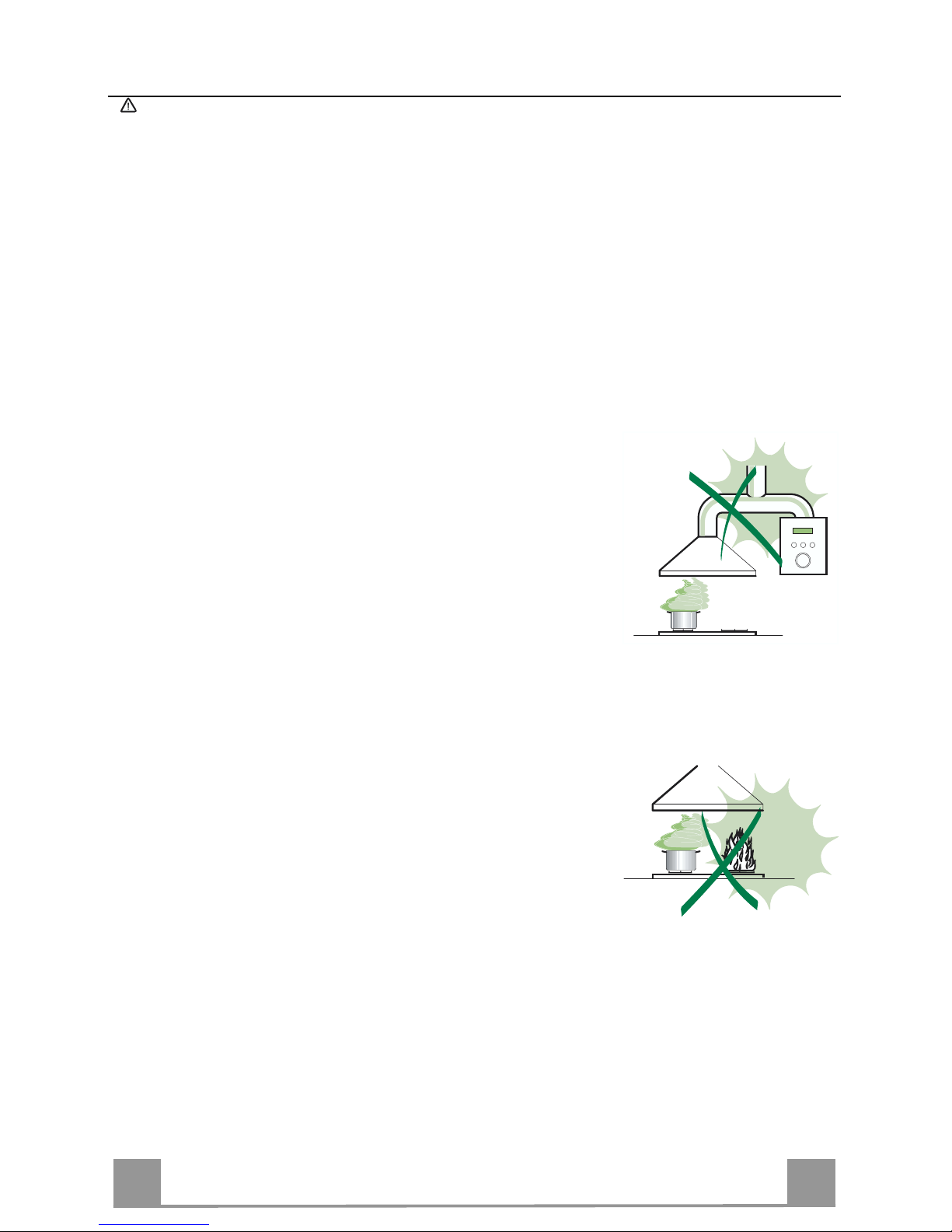
• Do not connect the extractor hood to exhaust ducts carrying combustion fumes
(boilers, fireplaces, etc. ).
• If the extractor is used in conjunction with non-electrical appliances (e.g. gas
burning appliances), a sufficient degree of aeration must be guaranteed in the
room in order to prevent the backflow of exhaust gas. The kitchen must have
an opening communicating directly with the open air in order to guarantee the
entry of clean air.
USE
• The range hood has been designed exclusively for domestic use to eliminate
kitchen o dors.
• Never use the hood for purposes other than for which it h as ben desi gned.
• Never leave high naked flames under the hood when it is in operation.
• Adjust the flame intensity to direct it onto the bottom of the pan only, making
sure that it does not engulf the sides.
• Deep fat fryers must be continuously monitored during use: overheated oil can
burst into flames.
• The hood should not be used by children or persons not instructed in its correct use.
CARE
• Switch off or unplug the appliance from the main supply before carrying out
any maint enance work .
• Clean and/or re place the Filters af ter the specified time period.
• Clean the hood using a damp cloth and a neutral liquid detergent..
Page 7

EN
7
7
DIMENSIONS and MAIN PARTS
Dimensions
''
''
''
''
''
''
''
''
''
''
''
Page 8
EN
8
8
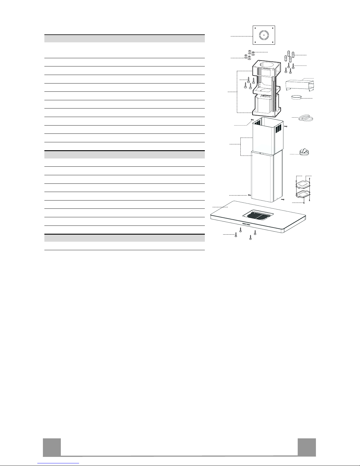
Components
Ref. Q.ty Product Components
1 1 Hood Body, complete with: Controls, Light, Blower,
Filters
2 1 Telescopic Chimney comprising:
2.1 1 Upper Section
2.2 1 Lower Section
7.1 1 Telesc opic frame complet e with extr actor, consisting of:
7.1a 1 Upper frame
7.1b 1 Lower frame
10 1 Flange ø 6”
10a 1 Damper
15 1 Air Outlet Connect ion
24 2 Connection Box
25 2 Pipe clamps
Ref. Q.ty Installation Components
11 4 Wall Plugs (If supplied)
12c 6 Screws 1/8” x 1/4"
12e 2 Screws 1/8” x 3/8”
12f 4 Screws M1/4” x 3/8”
12g 4 Screws M1/4” x 3” 1/8
12h 4 Screws 3/16” x 2” 3/4
21 1 Drilling template
22 4 1/4” int. dia washers
23 4 M1/4” nuts
Q.ty Documentation
1 Instruction Manual
7.1a
7.1
22
23
12h
7.1b
2
2.1
2.2
12c
11
21
12g
1
12f
15
12c
25
10
12c
24
12e
10a
Page 9
EN
9
9
INSTALLATION
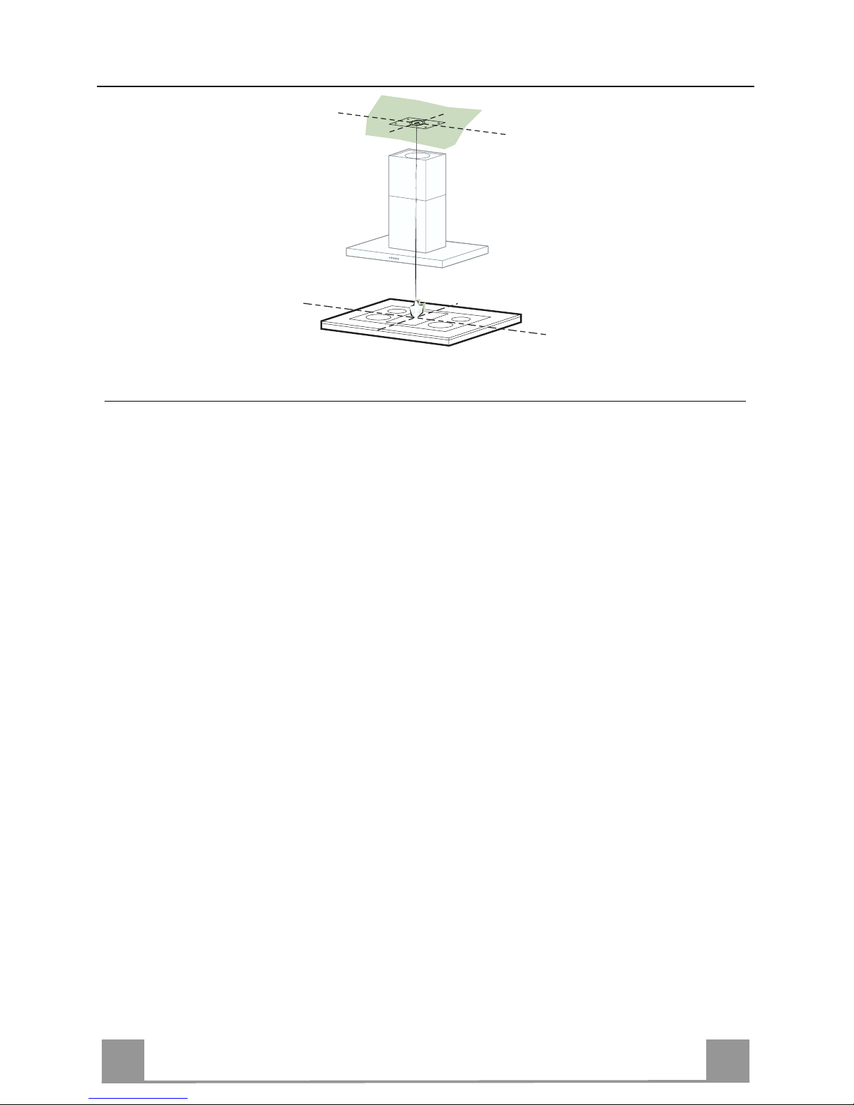
Drilling the Ceiling/shelf and fixing the frame
DRILLING TH E CEILING/SHE LF
• Use a plumb line to mark the center of the Cooking surface on the ceiling/support shelf.
• Place the drilling template 21 provided on the ceiling/support shelf, making sure that the
template is in the correct position by lining up the axes of the template with those of the hob.
• Mark the centers of the holes in the template.
• Drill the holes at the points marked:
• For concrete ceilings, drill for plugs appropriate to the screw size.
• For hollow brick ceilings with wall thickness of 13/16“: drill ø 3/8” (immediately insert
the Dowels 11 if supplied).
• For wooden beam ceilings, drill according to the wood screws used.
• For wooden shelf, drill ø 1/4".
• For the power supply cable feed, drill ø 3/8”.
• For the air outlet (Ducted Version), drill accord ing to the diameter of the extern al air ex-
haust duct connection.
• Insert two screws of the following type, crossing them and leaving 3/16“ from the ceiling:
• For concrete ceilings, use the appropriate plugs for the screw size (not provided).
• for Cavity ceiling with inner space, with wall thickness of approx. 13/16“, Screws 12h,
supplied.
• For wooden beam ceilings, use 4 wood screws (not provided).
• For wooden shelf, use 4 screws 12g with washers 22 and nuts 23, provided.
Page 10

EN
110
Fixing the frame
• Loosen the two screws fastening the lower chimney and remove this from the lower frame.
• Loosen the two screws fastening the upper chimney and remove this from the upper frame.
If you wish to adjust the hei gh t of the frame, proceed as follows:
• Unfasten the eight metric screws joining the two columns, located at the sides of th e frame.
• Adjust the frame to the height required, then replace all the
screws removed as above.
• Insert the upper chimneystack from above, and leave it running
free on the frame.
• Lift up the frame, fit the frame slots onto the screws up to the
slot end positions.
• Tighten the two screws and fasten the other two screws provided with the hood.
Before tightening the screws completely it is possible to adjust
the frame by turning it. Make sure that the screws do not come
out of their seats in the slotted holes.
• The frame mountings must be secure to withstand the weight
of the hood and any stresses caused by the occasional side
thrust applied to the device.
On completi on, check that t he base is stable, even i f the frame
is subjected to bending.
• In all cases where the ceiling is not strong enough at the suspension point, the installer must provide strengthening using
suitable plat es and backing pieces anch ored to the structural ly
sound parts.
Note: The Hood body should be secured to ceiling joists. If necessary, install a wood support behind the dry wall, flush mounted
between 2 joists. This will provide the necessary structure and
support for mounting.
2
2
1
1
Page 11

EN
111
Connections
DUCTED VERSION AIR EXHAUST SYSTEM
When installing the ducted version, connect the hood to the
chimney using a rigid 6” duct. (not supplied)
• Install the damper 10a ø 6”.
• Fix the duct in position using sufficient pipe clamps.
10 a
ø 150
25
DUCTLESS VERSION AIR OUTLET
• Fix the connection 15 to the frame using the 4 screws provided.
• Fix the flange 10 to the lower opening of the connection 15.
• Connect the hood air outlet to the flange in the lower part of
the junction using a rigid ø 6” tube (not supplied).
15
10
Chimney assembly - Mounting the hood body
• Position the upper chimney section and fix the upper part to the
frame using the 2 screws 12c provided.
• Similarly, position the lower chimney section and fix the lower
part to the frame using the 2 screws 12c provided.
Before fixing the hood body to the frame:
• Remove the grease filters from the hood body.
• Remove any activated charcoal fil ters.
• From below, use the 4 screws 12f provided to fix the hood
body to the frame.
12c
12f
12c
Page 12

EN
112
Electrical connection
• Remove the cover from the Field Wiring Co mpartment with a
phillips screwdriver.
• Feed the Power Supply Cable through the electrical knockout.
Connect the Po wer Supp ly Cable to th e range- ho od cab le. Attach the Power Supply Cable grounding lead to the green screw
provided. Attach the White lead of the power supply to the
White lead of the rangehood with a twist-on type wire connector. Attach the Black lead of the power supply to the Black
lead of the rangehood with a twist-on type wire connector.
• Replace the cover.
• Connect the control connector Cmd.
• P lace the Connector in the junction box 24 an d close it using
the 2 screws 12e provided.
• Fix the junction box to the hood body using the 2 screws 12c
provided.
• Connect the lights connecto r Lux.
Power supply cable
Green
Ground
screw
Ground wire
24
12e
Cmd
12c
Lux
Page 13

EN
113
USE
S
V1V1V1V1V1V1V1V1V1V1V1V1V1V1V1V1V1V1
V2
V3
L
Control board
L Light Switches the lighting system on and off.
S Led Motor running led.
V1 Motor Switches the extractor motor on and off at low speed. Used to provide a
contin-uos and silent air change in the presence of light cooking vapours.
V2 Speed Medium speed, suitable for most operating conditions given the optimum
treated air flox/noise level ratio.
V3 Intensive Maximum speed, used for eliminating the hi ghest cookin g vapour emission,
including long periods.
Page 14

EN
114
CARE
Grease filters
CLEANING METAL SELF- SUPPORTING GREASE FILTERS
• The filters must be cleaned every 2 months of operation, or
more frequently for particularly heavy usage, and can be
washed in a dishwasher.
• Remove the filters one at a time holding them up with one
hand and pulling the handle downwards with the other hand at
the same time.
• Wash the filters, taking care not to bend them. Allow them to
dry before refitting.
• When refitting the filters, make sure that the handle is visible
on the outside.
Activated charcoal filter (Recirculating version)
These filters (not supplied with the rangehood)are not washable
and cannot be regenerated, and must be replaced approximately
every 4 months of operation, or more frequently with heavy usage.
REPLACING OF THE FILTER
• Remove the metal grease filters.
• Remove the saturated charcoal filter by releasing the fixing
hooks
• Fit the new filter and fasten it in its correct position.
• Put the metal grease filters in their seats.
Lighting
LIGHT REPLACEMENT
20 W halogen light.
• Remove the 2 screws fixing the Lighting support, and pull it
out of from the Hood.
• Extract the lamp from the Support.
• Replace with another of the same type, making sure that the
two pins are properly inserted in the lamp holder socket holes.
• Replace the S upport, fixing it in place with the two scre ws removed as above.
Page 15

FR
115
TABLE DES MATIÈRES
AVERTISSEMENT ET CONDITIONS N ÉCESSAIRES......................................................................................................16
CONSEILS ET SUGGESTIONS ..........................................................................................................................................19
DIMENSIONS et PRINCIPALES PIÈCES............................................................................................................................20
INSTALLATION ....................................................................................................................................................................22
UTILISATION........................................................................................................................................................................26
SOIN ET ENTRETIEN..........................................................................................................................................................27
Page 16

FR
116
LIRE ET CONSERVER CES INSTRUCTIONS
L’installateur doit laisser ces instructions au propriétaire.
Le propriétaire doit conserver ces instructions en vue d’une utilisation subséquente et pour le bénéfice de l’inspecteur en électricité.
LISEZ BIEN CETTE FICHE AVANT D’UTILISER LA HOTTE
AVERTISSEMENT – POUR MINIMISER LE RISQUE D’UN FEU DE GRAISSE SUR LA CUISI-
NIÈRE : Ne jamais laisser un élément de la surface fonctionner sans sur v eillance à la puiss ance de ch auffage
maximale; un renversement/débordement de matière graisseuse pourrait provoquer un incendie ou causer de
la fumée. Utiliser toujours une puissance de chauffage moyenne ou basse pour faire chauffer de l'huile.
Veiller à toujours faire fonctionner le ventilateur de la hotte lors d’une cuisson avec une puissance de chauffage élevée ou lors de la cu isson d’un mets à fla mber (i.e. Crêp es Suzette, Ch erries Jubilee, Pepp ercorn B eef
Flambé). Nettoyer fréquemment les ventilateurs d’extraction. Veiller à ne pas laisser de la graisse
s’accumuler sur les surfaces du ventilateur ou des filtres. Utiliser toujours un ustensile de taille appropriée.
AVERTISSEMENT
– POUR RÉDUIRE LE RISQUE DE DOMMAGES CORPORELS APRÈS LE
DÉCLENCHEMENT D’UN FEU DE GRAISSE SUR LA CUISINIÈRE, APPLIQUER LES RECOMMANDATIONS SUIVANTES : Blessures en cas de feu suivre les recommandations suivantes :
ÉTOUFFEZ LE FEU AVEC UN COUVERCLE MÉTALLIQUE ET FERMEZ LE BRÛLEUR. FAITES
ATTENTION DE NE PAS VOUS BRÛLER. SI LE FEU NE S’ÉTEINT PAS IMMÉDIATEMENT, quit-
tez les lieux et appelez les pomp iers. ne touchez jama is une cassero le en flamm es – VOUS POURRIEZ
SUBIR DES BLESSURES. N’UTILISEZ JAMAIS DE L’EAU OU UN TORCHON MOUILLÉ POUR
ÉTEINDRE LE FEU – CE QUI POURRAIT CAUSER UNE EXPLOSION DE VAPEUR.
vapeur
brûlante.
Utiliser un extincteur SEULEMENT si :1. Il s’agit d’un extincteur de classe ABC, dont on
connaît le fonctionnement. 2. Il s’agit d’un petit feu encore limité à l’endroit où il s’est déclaré. 3. Les pompiers ont été contactés. 4. Il est possible de garder le dos orienté vers u ne sortie pendant l’op ération d e lutte
contre le feu.
N’utilisez un extincteur que si: 1. Vous avez sous la main un modèle ABC et vous comment
l’utiliser correctement. 2. Le feu est faible et peu répandu. 3. Les pompiers sont déjà prévenus. 4.
Vous conservez une sortie derrière vous.
TOUTE OUVERTURE DANS LE MUR OU LE PLANCHER À PROXIMITÉ DE LA HOTTE DOIT
ÊTRE SCELLÉ
Gardez 18 po. de hau teur en tre le bas d e la ho tte et la surface d e cuisso n . Con sultez l a fiche tech nique avant de découper les armoires. INSTALLATION DANS UNE MAISON MOBILE.
L’installation de cette hotte doit être conforme aux règlements de Manufactured Home Construction and Safety Standards, Titre 24 CFR, Section 3280 (anciennement Federal Standard for Mobile Home Construction and Safety, Titre 24, HUD, Section 280). Le branchement électrique
s’effectue avec un racco rdement à 4 fils. Consult ez l a Fiche Technique électrique.
EXIGENCES DE VENTILATION (ÉVACUATION)
ATTENTION – Afin de réduire le risque d’incendie et pour bien évacuer l’air, assurez-vous de faire échap-
per l’air des conduits à l’extérieur – Ne jamais évacuer l’a ir vers des espaces comportant des murs ou des
plafonds ou dans le grenier, la galerie ou le ga rage.
Déterminer la méthode d’évacuation de l’air la pl us appropriée pour l’application. La sortie
d’evacuation : soit par le mur, soit par le toit. Utilisez une longueur de tuyauterie minimale, incluant le
moins de coudes possible pour une plus grande effica cité. Le calibre de la tuyauterie doit être uniforme. N’ins tallez jamais 2 coudes ense mb les. Scellez bien tous les joints avec un ruban adhésif métallique à l'intérieur et scellez bien le clapet extérieur en utilisant du calfeutrage.
L’utilisation d’un tuyau d’évacuat ion flexible n’est pas re commandée. Les t uyaux flexibles
créent une contre-pression et de la turbulence, ce qui réduit la puissance d'évacuat ion.
Veillez à ce que l ’espace pour le tuyau soit amplement suffisant, ainsi vous n’aurez pas à découper les supports de mur intérieur. On ne doit couper une solive ou un poteau de colombage que
lorsque cela est abso lument nécessaire. S ’il est nécessaire de couper une soli ve ou un poteau du
colombage, on doit construire un e structure de support appropriée.
AVERTISSEMENT – Afin de réduire le risque d’incendie, utilisez seulement des conduits en métal.
Page 17

FR
117
AVERTISSEMENT
• Le système d’évacuation DOIT se terminer à l’ extérieur.
• N’ÉVACUEZ PAS le condu i t dans un grenier ou dans tout autre espace fermé.
• N’UTILISEZ PAS un clapet de sécheuse à 4 pouces.
• ON DÉCONSEILLE l’emploi de conduit d’évacuation flexible.
• N’ENCOMBREZ PAS la circulation d’air.
• Le fait de ne pas respecter ces avertissements pourrait occasionner un incendie.
FICHE TECHNIQUE ÉLECTRIQUE
Le raccordement électriq ue doit se faire avec u n circuit séparé de 15 ampères fusibles à 120 V,
60 Hz, courant alternatif. Nous recommandons un coupe-circuit. La taille du fusible doit se
conformer aux codes municipaux suivant la spécification électrique sur la plaque intérieure. CET
APPAREIL NE DOIT ÊTRE CONNECTÉ QU’EN UTILISANT DES FILS EN CUIVRE. Le
diamètre du fil devra aussi se conformer aux règlements du code national électrique,
ANSI/NFPA 70, ain si qu ’aux règl ement s lo caux et les sp éci ficatio n s de cet app areil . On peut obtenir ces informations auprès de :
National Fire Pr otection Association
Batterymarch Park
Quincy, Mass achusetts 02269
Raccordez cet appareil directement au coupe-circu it( ou au disjoncteur) par l’intermédiaire de
câble à conducteurs de cuivre, à blindage métallique flexible ou à gaine non-métallique. Un
serre-câble de ½ po. (12,7 mm) (homologation UL ou CSA) doit être installé à chaque extré-
mité du câble d'alimentation (sur la hotte et sur le boîtier de distribution).
Faites un trou de 1 ¼ po. dans le mur. S’il s’agit d'un mur en bois, sablez bien le trou. Tandis
qu'un trou dans le métal demande un oeillet (passe-fil).
AVERTISSEMENT – POUR RÉDUIRE LE RISQUE D’INCENDIE OU DE CHOC ÉLEC TRIQUE,
ne pas utiliser ce ventilateur en conjonction avec un dispositif de réglage de vitesse à semi-
conducteurs.
AVERTISSEMENT – POUR MINIMI SER LES RISQUES D’INCENDIE, CHOC ÉLECTRIQUES OU BLESSURES, OBSERVER CETT E RÈGLE :
suivez strictement les recommandations du
fabricant ; en cas de nécessité veuillez le contacter.
Avant d’entreprendre un travail d’entretien ou de nettoyage, interrompre l’alimentation de la
hotte au niveau du tableau de disjoncteur, et verrouiller le tableau de disjoncteur pour empêcher
tout rétablissement accidentel de l’alimentation du circuit. Lorsqu’il n’est pas possible de verrouiller le tableau de disjoncteur une étiquette d’avertissement proéminent interdisant le rétablissement de l’alimentation.
IMPORTANT :
Pour une ventilation de type général seulement. Ne pas utiliser cet appareil pour
l’évacuation de matières ou vapeurs explosives.
Page 18

FR
118
AVERTISSEMENT – POUR MINIMI SER LES RISQUES D’INCENDIE, CHOC ÉLECTRIQUES OU BLESSURES, OBSERVER CETT E RÈGLE :
l’installa tion et le raccordement électrique
ne doivent être effectués que par un technicien(s) qualifié, selon tous les codes municipaux
.
Afin d’obtenir un rendement maxim al en ce qui a trai t à la combustion ai nsi qu’à l’évacuation
des gaz par la conduite de cheminée et pour qu’il n’y ait pas de reflux des gaz de combustion, une bonne aération est nécessaire pour tous les appareils à combustion. Suivez les
conseils et mesures de sécur ité du fourniss eur tels que ceux publiés par la National Fire Protection Association (NFPA) et l’American Society for Heating, Refrigeration and Air Condi tion
Engineers (ASHRAE) ainsi que les codes munici paux.
Lors d’opération de découpage et de perçage dans un mur ou un plafond, veiller à ne pas
endommager les câblages électriques ou canalisations qui peuvent s’ y trouver.
Un conduit de ventilation doit toujours se terminer à l'extér ieur.
AVERTISSEMENT
• Une prise à la terre est nécessaire pour cette hotte.
• N’UTILISEZ PAS un tuyau à l’eau fro ide pour la mise à la terre s’il est connecté à du
plastique, un joint non métallique ou autre matériel.
• N’EFFECTUEZ PAS la mise à la terre sur la conduite de gaz.
• NE PAS INSTALLER un fusible dans le conducteur neutre ou le conducteur de liaison à
la terre.
• Vérifiez avec un électricien qualifié que la hotte est bien mise à la terre.
• Le fait de ne pas respecter ces avertissements pourrait occasionner un incendie.
Page 19

FR
119
CONSEILS ET SUGGESTIONS
Les instructions d’utilisation s’applique à plusieurs versions de ce type
d’appareil. En conséquence, il est possible que vous trouviez des descriptions
de caract éristiques ne s'appl iquant p as à votre appareil.
INSTALLATION
• Le fabrican t décline to ute re sponsabilité en ca s de dommage d û à une installation inadéquate ou n on confor me aux règles de l’art .
• Vérifiez que la tension du secteur correspond à la valeur qui figure sur la plaquette apposée à l’intérieur de la hotte.
• L’alimentation électrique doit être adéquatement et suffisamment mise à la
terre.
Connectez la hotte à la sortie de l’air aspiré à l’aide d’une tuyauterie d’un dia-
mètre ou supérieur à 6 po. Le parcours de la tuyauterie doit être le plus court
possible.
• Évitez de connecter la hotte à des conduites d’évacuation de fumées issues
d’une combustion t el que une chaudière, une chemi née, etc.
• Si vous utilisez des appareils qui ne fonctionnent pas à l’électricité dans la
pièce ou est installée la hotte (par exemple : des appareils fonctionnant au
gaz), vous devez prévoir une aération suffisante de l’espace. Si la cuisine en
est dépourvue, pratiquez une ouverture qui communique avec l’extérieur pour
garantir l’infiltration de l’air pur.
UTILISATION
• La hotte a été conçue exclusivement pour un usage domestique, dans le but
d’éliminer les odeurs de la cui sine.
• Ne jamais utiliser la hotte de manière abusive.
• Ne pas laisser les flammes libres à forte intensité lorsque la hotte est en service.
• Toujours régler les flammes de manière à éviter toute sortie latérale de ces
dernières par rapp ort au fond des cass eroles.
• Contrôler les friteuses lors de l’utilisation, car l’huile surchauffée pourrait
s’enflammer
• La hotte ne doit pas ê tre utilisée par de s enfant ou des p ersonnes ne pouva nt
pas en assurer une utilisation adéquate
ENTRETIEN
• Avant de procéder à toute opération d’entretien, retirer la hotte en la débranchant ou en la mettant hors -c i rc uit .
• Effectuer un entretien scrupuleux et en temps voulu des filtres.
• Pour le nettoyage des surfaces de la hotte, il suffit d’utiliser un linge humide et
un détergent liquide neutre.
Page 20

FR
220
DIMENSIONS et PRINCIPALES PIÈCES
Dimensions
''
''
''
''
''
''
''
''
''
''
''
Page 21

FR
221
Composantes
Réf. Qté Pièces du produit
1 1 Corps de la hotte équipé de : commandes, lumière,
groupe vent ilateur, filtres
2 1 Cheminée télescopique formée de :
2.1 1 Cheminée supérieure
2.2 1 Cheminée inférieure
7.1 1 Treillis télescopique incluant aspirateur, formé de :
7.1a 1 Treillis supérieur
7.1b 1 Treillis inférieur
10 1 Rosace ø 6”
10a 1 Clapet d’air
15 1 Raccord de sorti e d’air
24 2 Boîte connexions
25 2 Colliers de serrage
Réf. Qté Pièces servant à l’installation
11 4 Chevilles (si fournies)
12c 6 Vis 1/8” x 1/4"
12e 2 Vis 1/8” x 3/8”
12f 4 Vis M1/4” x 3/8”
12g 4 Vis M1/4” x 3” 1/8
12h 4 Vis 3/16” x 2” 3/4
21 1 Gabarit de perçage
22 4 Rondell es de 1/4” int. dia
23 4 Écrous M1/4”
Qté Documentation
1 Manuel d’instructions
7.1a
7.1
22
23
12h
7.1b
2
2.1
2.2
12c
11
21
12g
1
12f
15
12c
25
10
12c
24
12e
10a
Page 22

FR
222
INSTALLATION
Perçage du plafond / de l’étagère et installation du treillis
PERÇAGE DU PLAFOND / DE L’ÉTAGÈRE
• À l’aide d’un fil à plomb, faire une marque identifiant le centre de la cuisinière sur le plafond ou l’étagère de support.
• Placer le gabarit de perçage 21 sur le plafond ou l’étagère de support, en prenant soin de
vous assurer que le gabarit est à l’endroit approprié en alignant les axes de celui-ci avec
ceux de la hotte.
• Faire des marques au centre des trous sur le gabarit.
• Percer les trous aux endroits ainsi identifiés
• Pour les plafonds en béton : en fonction des goujons po ur bé ton utilisé s .
• Pour les plafonds en briques avec chambre à air, avec épaisseur résistante de 13/16“: per-
cer ø 3/8” (insérer immédiatement les chevilles 11, si fournies).
• Pour les plafonds en poutrage en bois : en fonction des vis à bois utilisées.
• Étagère en bois : ø 1/4".
• Passage du câble électrique d’alimentation : ø 3/8”.
• Sortie air (version aspirante) : en fonction du diamètre de la connexion avec les tuyaux
d’évacuation externe.
• Insérer deux vis en les croisant et en laissant 3/16“ de distance par rapport au plafond :
• pour le béton, utiliser des goujons pour béton (non fournis).
• pour briques percées, ayant une épaisseur résistante d'environ 13/16“, utiliser les vis 12h.
• pour le poutrage en bois, 4 vis à bois (non fournies).
• pour étagère en bois, 4 vis 12g avec rondelles 22 et écrous 23.
Page 23

FR
223
Installation du treillis
• Dévisser les deux vis qui fixent la cheminée inférieure et sortir
cette dernière du treillis (depuis la partie inférieure).
• Dévisser les deux vis qui fixent la cheminée supérieure et sortir
cette dernière du treillis (depuis la partie supérieure).
Si l’on souhaite régler la hauteur du treillis, effectuer les opérations suivantes :
• Dévisser les hu it vis métriques qui unissent les d eux colonnes,
qui se trouvent sur les côtés du treillis.
• Régler la hauteur souhaitée du treillis et revisser les vis qui ont
été précédemment retir ées.
• Insérer la cheminée supérieure depuis le haut et la laisser libre
sur le treillis.
• Soulever le treillis, encastrer les oeillets sur les vis et faire coulisser jusqu’à la butée.
• Serrer les d eux vis et visser les d eux autres vis fournies avec
l’appareil.
Avant de serrer définitivement les vis, il est possible d’effectuer
des réglages, en d épl açant le t reillis, tou t en cont rôlan t qu e les vis
ne sortent pas du logement de l’œillet de réglage.
• L’installation du treillis doit être solide, en fonction du poids
de la hotte et des contraintes provoquées par les poussées latérales occasionnelles auxquelles l’appareil sera soumis.
Après avoir effectué l'installation, vérifier que la base soit sta-
ble, même si le treillis est soumis à des contraintes de flexion.
• Dans tous les cas où le plafond ne devait pas être suffisamment
robuste en corresp ond ance du po int d ’accro chage, l’i nst allat eur
devra se charger de le rendre plus solide au moyen de plaques
et contre-plaques sp éciales, ancrées sur les parties structuralement résistantes.
Note: Le corps de la hotte devrait être fixer aux solives du plafond. Si nécessaire, installer un support en bois derrière l a paroi
sèche, à mi-chemin ent re deux solives. Cela fournira la structure
et le soutien nécessai r e au montage.
2
2
1
1
Page 24

FR
224
Branchements
SORTIE D’AIR VERSION ASPIRANTE
En cas d’install ation en version aspirante, brancher la ho tte à la
tuyauterie de sortie via un tube rigide de 6 po. (non fourni)
• Installer le clapet d’air 10 ø 6 po.
• Fixer le tube par des colliers appropriés.
10 a
ø 150
25
SORTIE D’AIR VERSION FILTRANTE
• Fixer le raccord 15 au treillis à l’aide des 4 vis fournies.
• Fixer la rosace 10 à l’ouverture inférieure du raccord 15.
• Joindre la sortie d’air de la hotte à la rosace à l’endroit inférieure de la jonction à l'aide d'un tube rigide de 6” (non fourni).
15
10
Montage cheminée – Montage du corps de la hotte
• Positionner la cheminée supérieure et fixer cette dernière dans
la partie supérieure du treillis à l'aide de 2 vis 12c.
• De l a même façon, positionner la cheminée in férieure et fixer
cette dernière dans la partie inférieure du treillis à l'aide de 2
vis 12c.
Avant de fixer le corps de la hotte au treillis :
• Retirer les filtres anti-graisse du corps de la hotte.
• Retirer les éventuels filtres anti-odeur au charbon actif.
• Ensuite, fixer par le bas, au moyen de 4 vis 12f , le corps de la
hotte au treillis.
12c
12f
12c
Page 25

FR
225
BRANCHEMENT ÉLECTRIQUE
• Retirer le couvercle du compartiment de filage à l’aide d’un
tournevis Phillips.
• Passer le câble d’alimentation dans la pastille enfonçable.
Brancher le câble d’alimentation sur la hotte. Attacher le
conducteur de mise à la terre du câble d’alimentation à la vis
verte fournie. Attacher le fil blanc d u câble d’alimentation au
fil blanc de la ho tte avec une cosse (conn ecteur de fils). Attacher le fil noir du câble d’alimentation au fil noir de la hotte
avec une cosse (conn ect eur de fils).
• Replacer le couvercle.
• Connecter le Connecteur des Commandes Cmd.
• Ranger le Connecteur dans la Boîte de protection 24 en la fermant à l’aide des 2 Vis 12e fournies avec l’appareil.
• Fixer la Boîte de protection au Corps de la Hotte à l’aide des 2
Vis 12c fournies avec l’apparei l .
• Connecter le Connecteur de l’Eclairage Lux.
Câble d'alimentation
d'énergie
Vis moulue
verte
Fil de masse
24
12e
Cmd
12c
Lux
Page 26

FR
226
UTILISATION
S
V1V1V1V1V1V1V1V1V1V1V1V1V1V1V1V1V1V1
V2
V3
L
Tableaux des commandes
L Lumières Allume et éteint l’installation de l’éclairage.
S Del Del allumage Moteur.
V1 Moteur Met en marche et à l’arrêt le moteur aspiration à vitesse minimale, pour un
rechange d’air permantent particulièrement silencieux en cas de faibles vapeurs de cuisson.
V2 Vitesse Vitesse moyenne pour la plupart des conditions d’utilisation, étant donné le
rapport optimal entre débit d’air traité et niveau sonore.
V3 Vitesse Vitesse maximum, pour faire face aux émissions maximum de vapeur de
cuisson, même pendant des temps prolongés.
Page 27

FR
227
SOIN ET ENTRETIEN
Filtres anti-graisse
NETTOYAGE FILTRES ANTI-GRAISSE METALLIQUES AUTOPORTEURS
• Lavables au lave-vaisselle, ils doivent être lavés environ tous
les 2 mois d’emploi ou plus fréquemment en cas d’emploi particulièrement intense.
• Enlevez les filtres l’un après l’autre en les soutenant avec une
main et en tirant en même temps la poignée vers le bas avec
l’autre main.
• Laver les filtres en évitant de les plier et les laisser sécher avant
de les remonter.
• Remonter les filtres en veillant à ce que la poignée reste vers la
partie visible externe
Filtre anti-odeur (Version filtrante)
(Les filtres ne sont pas fournis avec la hotte)Il ne sont pas lavables ni régénérables, il faut les remplacer au moins tous les 4
mois d’emploi ou plus fréquemment en cas d’emploi particulièrement intense.
Changement des filtres
• Retirer les filtres à graisse métalliques.
• Retirer le filtre anti-odeur au charbon actif saturé en agissant
sur les crochets qui l e tiennent en place.
• Mettre le nouveau filtre en l’accr ochant bien en place, puis remonter les filtres à graisse métalliques
Éclairage
REMPLACEMENT DES AMPOULES
Lampe halogène de 20 W.
• Reti rer les 2 vis qu i fixent le supp ort éclairage et reti rer ce dernier de la hotte.
• Extraire l’ampoule du support.
• Remplacer par un e nouvelle ampoule possédant les mêmes caractéristiques, en veillant à ce que les deux fiches soient
correctement insérées dans le logement de la douille.
• Remonter le support en le fixant à l’aide des deux vis précédemment retirées.
Page 28

436003944_01 - 070717
 Loading...