

Frank Door TS-727 Service Manual
TS-727
MICROPROCESSOR CONTROL SYSTEM
START-UP AND
TROUBLESHOOTING GUIDE
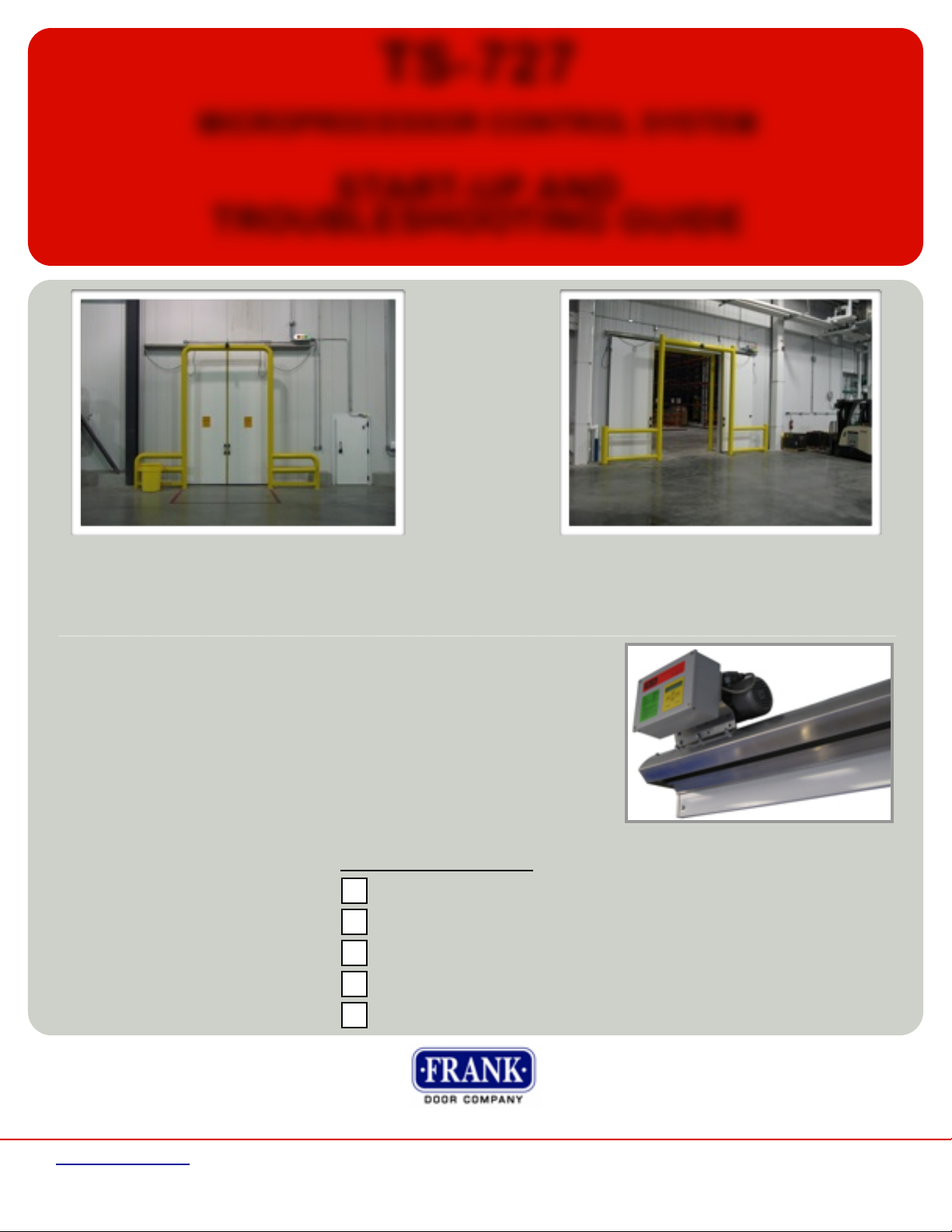
THE BEST IN COLD STORAGE DOOR AUTOMATION
Frank Door Company offers the best drive system available supported by unprecedented technical support.
Technical support for the system is available Monday - Friday, 8am - 5pm EST.
This microprocessor based door drive system
provides unprecedented control and flexibility
in automated door applications for a variety of
cold storage uses. The push of a button will
activate the self-learning software. This unique
feature is only available at Frank Door.
The operator sets its own limits and offers
multiple points of control. The TS727 system
can be precisely set to regulate door position,
opening and closing speeds, partial openings,
and time-delay closing. The system employs
field-proven technologies in a package that
provides complete, highly flexible control of the
door’s action.
The control system is fully integrated involving
no torque limiters so even large and heavy
power doors operate smoothly and reliably, no
matter what the conditions. Built in heaters
for the drive unit and controller are standard,
allowing for applications below 0C (32F).
In particular, the system stands up to frequent
openings and closings and functions without
problems in humid or cold conditions.
Additional features of the TS727 control system
include soft start and stop, a programming
keypad, password protection, a cycle counter,
electronic overload protection and sophisticated
internal diagnostics.
This Unit Is Pre-Wired For:
208/1/60
230/1/60
400/1/60
460/1/60
480/1/60
Technical Data
Mains Volt: 208 / 230 / 400 / 460 / 480 VAC / 1 / 60
Power Consumption: 4.5 Amp (Maximum)
Output Voltage (secondary): 24VDC
Power Supply (secondary): max. 1020mA
Output Voltage to motor: 230 VAC (3-phase)
Motor Rating: max. 370 watts
Dimensions: H x W x D = 8” x 12” x 4.5”
413 Howard Blvd., Newport, North Carolina USA 28570
www.frankdoor.com toll free (888)833-3667 phone (252)223-1112 fax (252)223-1116
1
START-UP
PARTIAL OPEN
CLOSE
STOP / LOCK
OPEN
+ 24 VDC -
SAFETY DEVICE #2
SAFETY DEVICE #1
RED WIRE
WHITE WIRE
BLACK WIRE
BLACK WIRE
ELECTRICAL CONNECTIONS
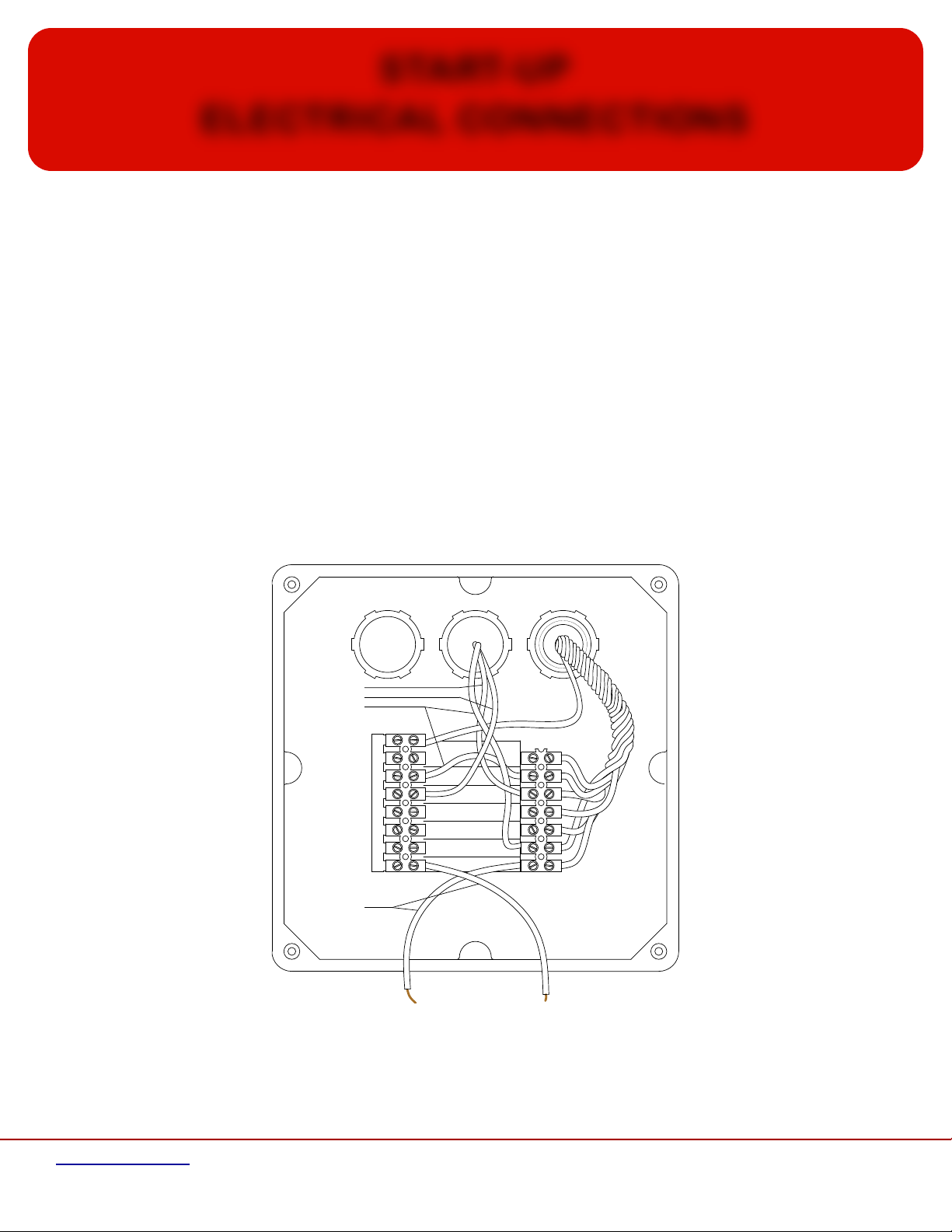
I/1 Connection of external devices
Connect all wires from the external devices (loop detectors, pull cords, push buttons, motion detectors, etc.) to the external leads of
the controller per instructions below in Section I/2 & I/3 (leads are located in service box mounted to controller labeled “24 Volts”). This
drive system utilizes an electronic position control system (encoder), no additional limit switches are required. The encoder is
recognized automatically by the control system. Make sure there is a lockable switch in the supply line to control system that will cut off
the power supply completely. Furthermore, a separate fuse must be provided on the site to protect the supply line and the
connection terminals of the control system.
I/2 Wiring connections for pull switch stations, 2-button switch
Note: Pull switch stations & 2-button switches (if supplied) must be wired normally open & in parallel.
Connect pull switch stations to terminals labeled “OPEN”
Connect “Open/Close” feature of 2-button switch (if supplied) to terminals labeled “OPEN”
Connect “Partial Open” feature of 2-button switch (if supplied) to terminals labeled “PARTIAL OPEN”
I/3 Wiring connections for reversing edge, locks (if applicable)
Plug in lead(s) from reversing edge to connector on trailing edge side of header. On biparting doors,
there is a connector on each side of header. Leads on door are labeled “24 Volts”.
413 Howard Blvd., Newport, North Carolina USA 28570
www.frankdoor.com toll free (888)833-3667 phone (252)223-1112 fax (252)223-1116
2
START-UP
FUSE F1: T 4.0 A
ELECTRICAL CONNECTIONS
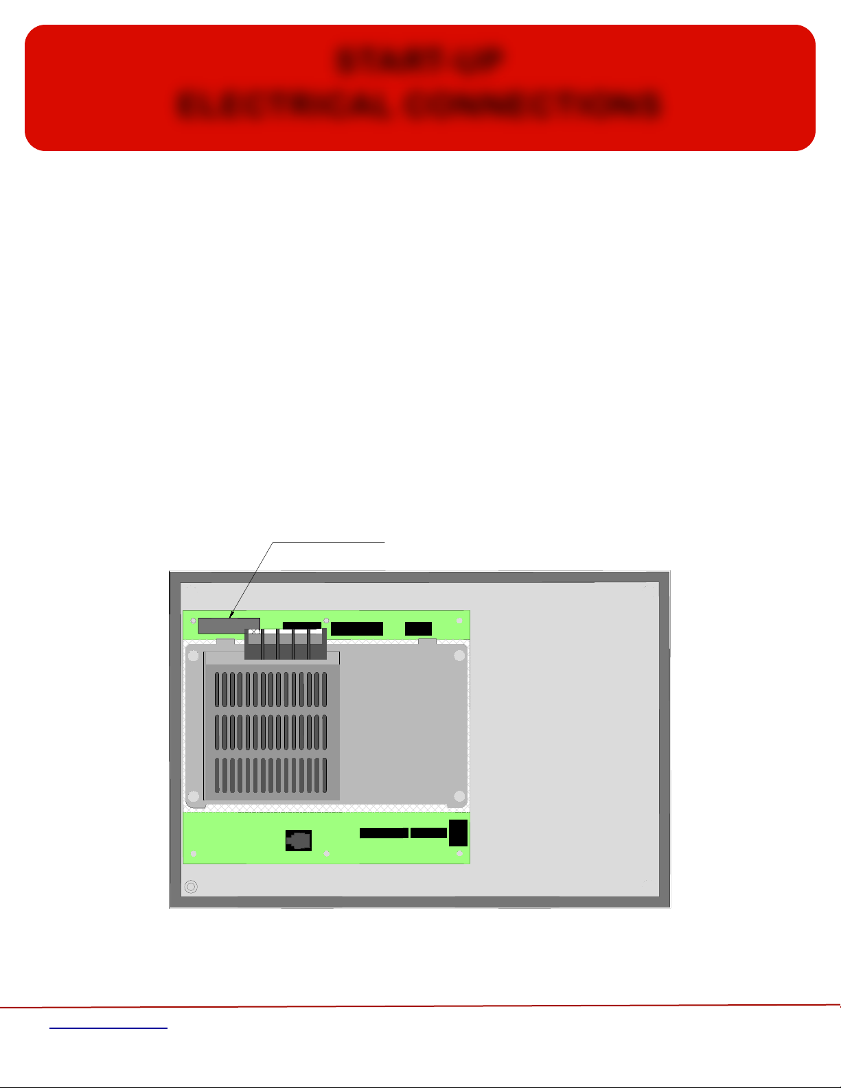
I/4 Wiring connections for radio receiver (if supplied)
Radio receiver is pre-wired in the factory. If a radio receiver is added after initial installation:
Connect RED wire from radio receiver to terminal labeled “+24 VDC” on left buss
Connect BLACK wire from radio receiver to terminal labeled “+24 VDC” on right buss
Connect GRAY wires from radio receiver to terminals labeled “OPEN”
I/5 Wiring connections for motion detector (if supplied)
Please follow manufacturer’s instructions for motion detector
Note: Both “Open” & “Close” Controls must be set at “Full Travel”
“Automatic Closing” must be set to “On”
I/6 Location of fuses
FUSE Fuse F1: T 4.0 A
Main fuse (time-lag fuse)
(Complete 230V AC supply)
413 Howard Blvd., Newport, North Carolina USA 28570
www.frankdoor.com toll free (888)833-3667 phone (252)223-1112 fax (252)223-1116
3
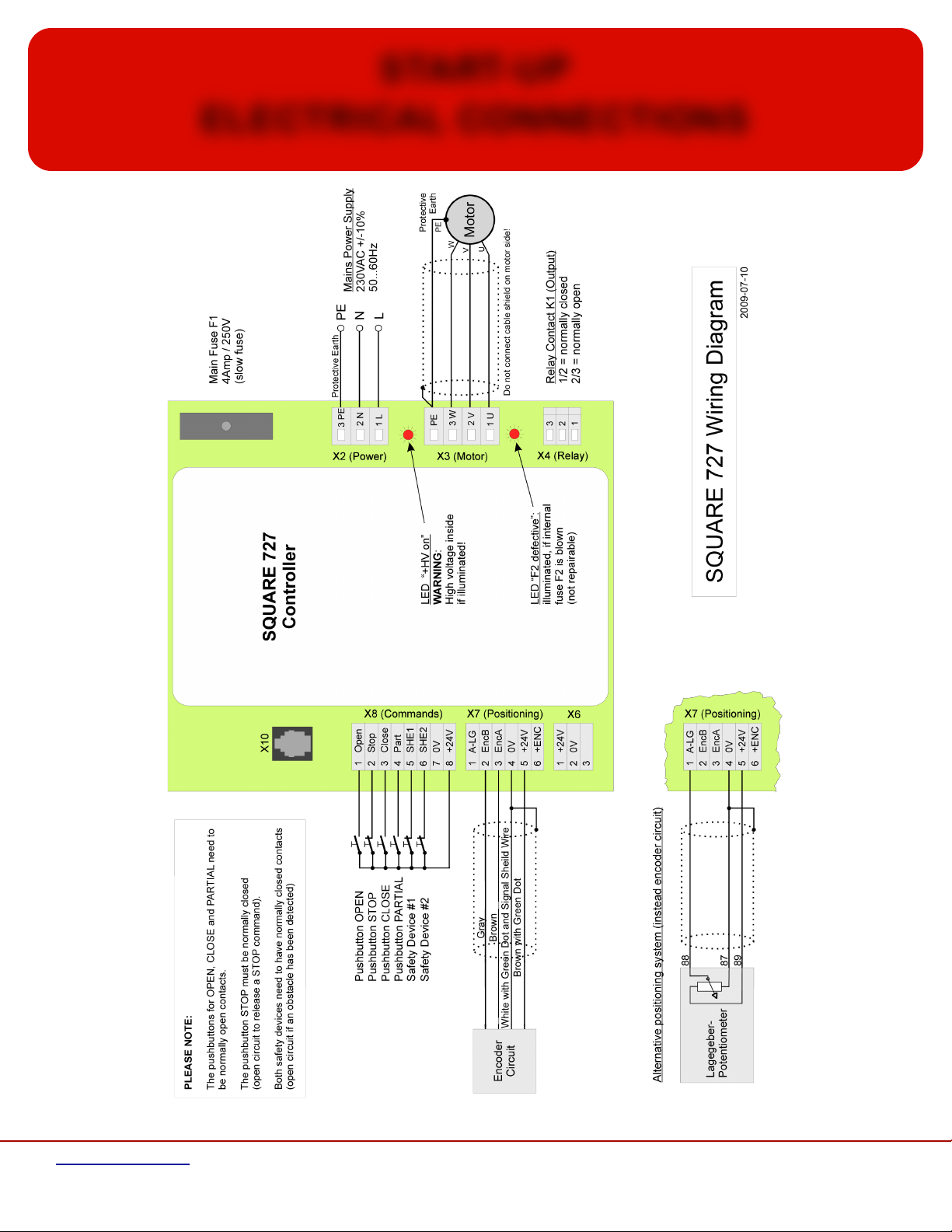
START-UP
ELECTRICAL CONNECTIONS
413 Howard Blvd., Newport, North Carolina USA 28570
www.frankdoor.com toll free (888)833-3667 phone (252)223-1112 fax (252)223-1116
4

START-UP
PROGRAMMING / ADJUSTMENTS
All adjustments and programming are carried out with the membrane keys and the LCD display on the lid of the control system.
On page 10, you will find the adjustment menu with all adjustable functions and values. Please mark in the right hand column, the
values you adjusted in your control system. Detailed information on how to adjust the speeds and the positions of the door can be
found on pages 8 and 9.
WARNING: Never make any adjustments when the door is moving!
RECOMMENDED TO BE USED IN TEMPERATURES ABOVE 0ºC (32ºF)
(Please see Adjustment Instructions for Motor/Controller Heat on page 8)
II/1 Operation
1) Switch on the mains power supply. The LCD display on the lid will show the software version for a short time. Afterwards, it switches to
“Find Encoder Limits Automatically - ENT”. (Do not press “ENTER” at this time! See Section II/3 Adjustment/Programming on the following
page first.)
2) You can choose between English, German, French, Italian, and Spanish (the default is set to English).
3) The password is preset in the factory at “0000”. When the display asks for a password, press the “ENT” key. This will allow
you easy access to all functions of the controller. Once you have finished making adjustments, go to “Select New Password” in the
menu and enter a new password to protect your adjustments. Please note your password and keep in a secure place. Detailed
information on how to select a new password can be found on page 9.
4) If none of the keys are pressed for more than 10 minutes, the display returns back to the highest level of the menu (“POWER
ON / SYSTEM OK”). This is a safety function that prevents anyone from making any adjustments without the proper password.
II/2 Functions of the keys
With the “ENT” key (ENTER)
...you select the just displayed point of the menu
...you go to the next lower level of the menu
...you open the input area within the angle brackets (input area is flashing)
...you confirm and enter the values adjusted in the flashing input area
With the “ESC” key (ESCAPE)
...you go back to the previous, higher, menu level
...you leave the opened flashing input area without selecting and entering the adjusted values
With the arrow keys (UP & DOWN)
...you select a function within one menu level
...you adjust the value in the opened flashing input area
413 Howard Blvd., Newport, North Carolina USA 28570
www.frankdoor.com toll free (888)833-3667 phone (252)223-1112 fax (252)223-1116
5
 Loading...