

Page 1

INSTALLATION
INSTRUCTIONS
FOR SECTIONAL OVERHEAD
(STANDARD LIFT)
DO NOT DISCARD
413 HOWARD BLVD.
NEWPORT , NC 28570
1.888.833.3667
FAX 252.223.1116
www.frankdoor.com
1
Page 2

INSTALLATION GUIDELINES FOR SECTIONAL OVERHEADS
BEFORE YOU INSTALL YOUR FRANK DOOR, PLEASE REVIEW THESE BASIC GUIDELINES
INSTALLATION SHOULD BE PERFORMED BY A PROFESSIONAL OVERHEAD DOOR
INSTALLATION COMPANY OR YOUR WARRANTY IS NULL AND VOID. IF YOU ARE NOT A
PROFESSIONAL OVERHEAD DOOR INSTALLER, PLEASE DO NOT ATTEMPT TO INSTALL.
IMPROPER INSTALLATION CAN RESULT IN SERIOUS INJURY OR DEATH!
1. All doors must be inst alled on plumb walls. Any walls out of plumb will require that the door frames be
shimmed back to plumb. All door frames must be inst alled plumb and square to insure proper operation
and warranty .
2. All headers and side casings should be bolted through the wall that they are inst alled on.
3. Doors mounted on insulated panels should have backup headers and side casings to help strengthen the
opening.
4. Doors mounted on very tall panel walls will require support steel to be added to the wall around the door
opening. Support steel, if required, is to be supplied and specified by others.
5. Check that the inside of the steel vertical tracks are free of any debris that may impede the travel of the
wheel assemblies
6. The exterior and interior edges of headers and side casings should be caulked with silicone to prevent
any moisture migration behind the components that may cause frost or sweating.
before
operating door.
POWER OPERATED SECTIONAL OVERHEADS
UNDER NO CIRCUMSTANCES SHOULD ANY CHANGES BE MADE TO THE WIRING OF THE
OPERATOR OR THE DOOR. IF THERE ARE ANY QUESTIONS, ALWAYS CONTACT FRANK
DOOR. FAILURE T O DO SO WILL VOID THE DOOR’S W ARRANTY.
1. Always consult and comply with all local electrical codes. Ensure that the licensed electrician is aware of
the voltage and amperage requirements of the door and uses the proper size wire and power supply .
All
freezer doors should be supplied with an uninterrupted and separate power supply for the antifrost heaters.
2. Overhead pull switches which activate the power operator should be positioned far enough away from
the door opening to allow the door to be in the full open position before any vehicle arrives at the opening.
Doing so will help prevent damage to the door panel.
2
Page 3

INSTALLATION PROCEDURE FOR SECTIONAL OVERHEADS (STANDARD LIFT)
01. Check & inspect all crates for damage. The freight company is responsible for any damage. The purchaser should file claims with the freight company immediately .
02. ALL DOORS & DOOR FRAMES MUST BE INST ALLED PLUMB & SQUARE T O ENSURE PROPER
OPERA TION & WARRANTY V ALIDA TION. V erify that walls are plumb. Any walls out of plumb will require
that the door frames be shimmed back to plumb.
03. After it has been established that walls are plumb, the installation of side casings, header & door can
begin.
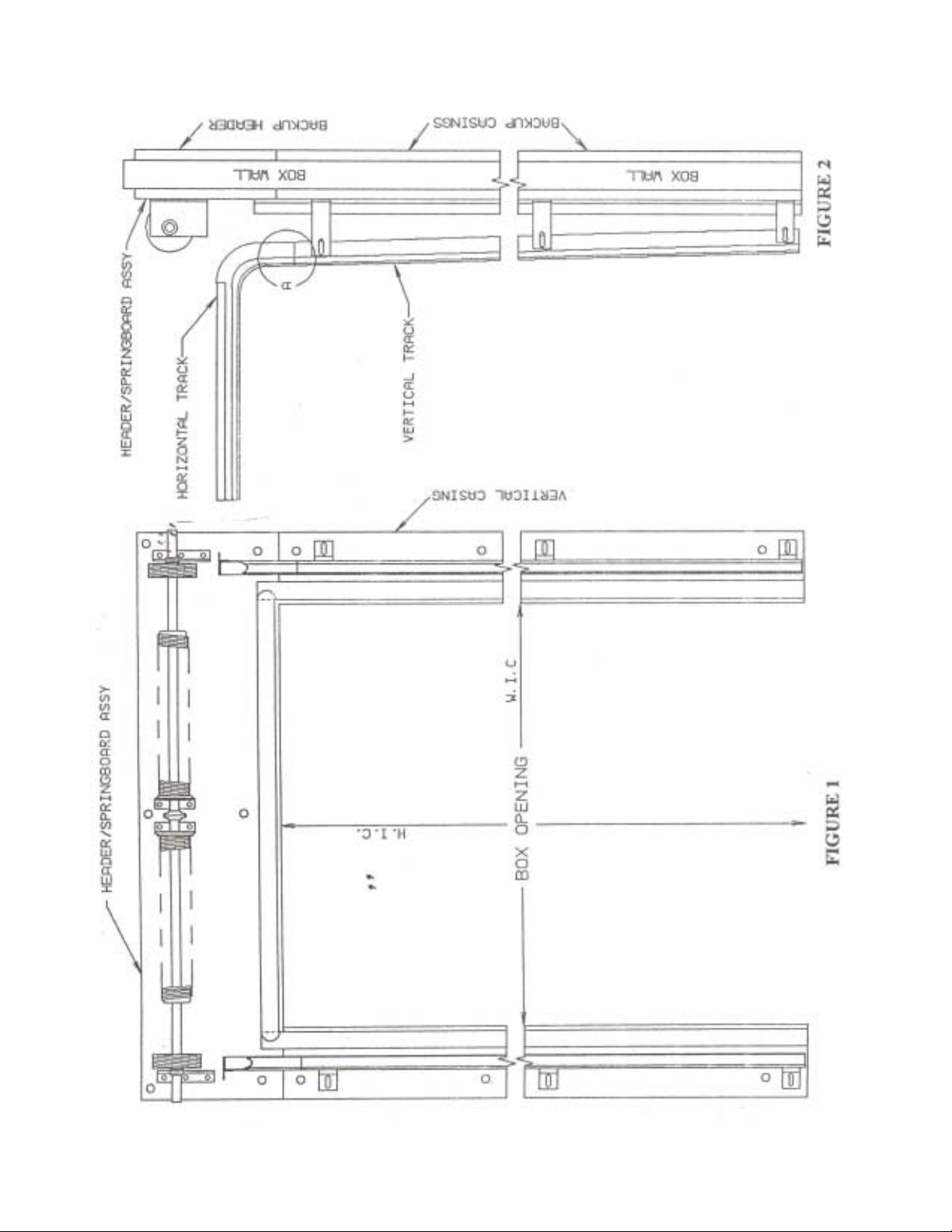
04. Place casings by the door opening parallel to and even with its edge. Ensure that the distance between
them is equal to the specified width in (WIC).
05. Use carriage bolts supplied to fasten the casings to the wall. Drill 3/8” diameter holes through the
casing, insulated box wall and backup casings (if applicable). Install bolts (minimum of three) and loosely
tighten nuts onto through bolts.
06. Lift header assembly above the installed casings. The header gasket should fit between the gaskets
attached to the casings. Ensure that the distance from the floor to the bottom of the header is approximately
equal to the specified height in clear (HIC).
07. Drill 3/8” diameter holes through the header , insulated box wall and backup header (if applicable). Install
bolts (minimum of six) and loosely tighten nuts onto through bolts.
Note: Carriage bolts should be installed
approximately every 30” for both header and casings.
08. Check header and casings for plumb and common plane. If necessary , loosen bolts and add shim(s) as
required. Caulk all edges of casings and header that contact box wall and/or floor with silicone sealant.
Tighten all bolts.
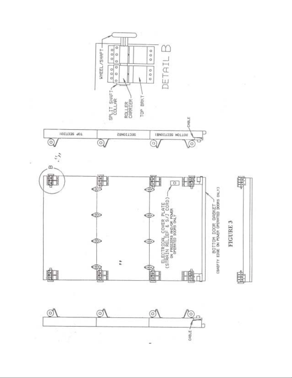
09. Position bottom section #1 (with gasket) in center of opening, allowing equal distance from each side of
the opening. Door section should be approximately 1 3/4” away from casings on either side of opening,
allowing the door to just make contact with casing gaskets. Prop door section in such a manner as to allow
it to stand by itself.
10. Remove four corner bracket roller carriers and slide a roller shaft into each pair of carriers. Slip rollers
into track and reattach roller carriers to corner brackets.
11. Position next section #2 on top of bottom section #1. Align in opening and with bottom section #1.
Remove two top bracket roller carriers and slide a roller shaft into each pair of carriers. Slip rollers into track
and reattach roller carriers to top brackets. Attach hinges from bottom section #1 to section #2 using screws
supplied.
12. Complete the remainder of the sections at this time following step # 1 1. The top door section should only
be installed after horizontal (curved) tracks have been installed.
3
Page 4

INSTALLATION PROCEDURE FOR SECTIONAL OVERHEADS (STANDARD LIFT) (CONT’D)
HORIZONTAL TRACK INSTALLATION
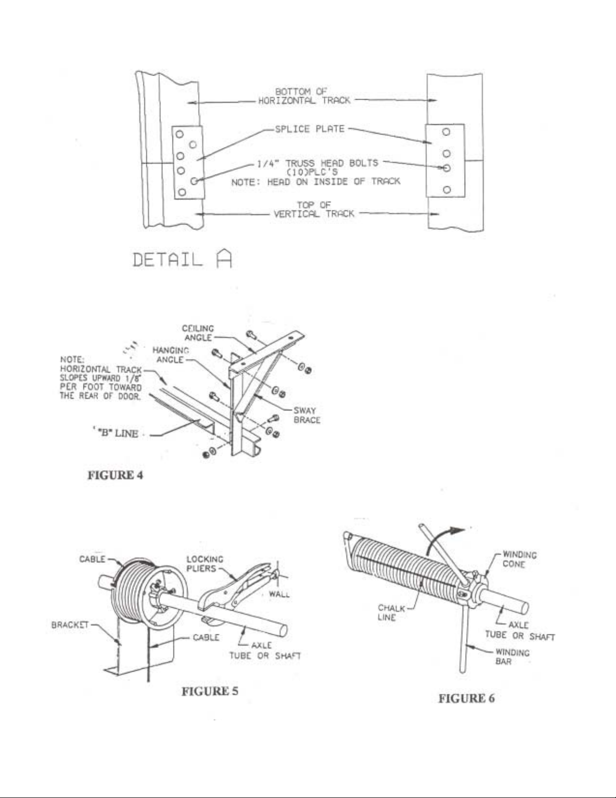
01. Locate horizontal (curved) track with curved end down and mate with vertical track section. Secure
using supplied splice plate and associated hardware.
Note: Horizontal track slopes upward 1/8” per foot
towards rear of door.
02. Verify that horizont al tracks (left/right) are p arallel to each other and secure them to each other with
supplied “B” line and fasteners at far end.
03. Verify that horizont al tracks are level to each other and secure in place using threaded rod (not supplied)
between “B” line attached to side of horizontal tracks and convenient overhead structural members or ceiling of box.
04. Install sway braces (not supplied) only after checking and verifying that horizontal tracks are parallel.
Note: Support structure must be strong enough to support full door weight.
05. After door panels have been installed and placed in the fully open position, attach door bumpers 1”
behind the top wheels and secure using supplied hardware.
TOP DOOR SECTION INSTALLATION
01. Place the top section in position and align with previous section. Remove two top bracket roller carriers
and slide a roller shaft into each pair of carriers. Slip rollers into track and reattach roller carriers to top
brackets. Att ach hinges from previous section to top section using screws supplied.
02. Adjust bracket slides on all roller carriers so that each section is perfectly vertical.
03. Check track and door for proper clearances and adjust as necessary . Secure all fasteners.
04. Install split shaft collars onto end of bottom two roller shafts of bottom section and the top two roller
shafts of top section to prevent side movement of door .
Note: To ensure that the required pitch of the track is obtained, the tracks for this door have been
preset as close as possible in the factory. It is recommended that you adjust the seal of the door by
using the adjustment on the roller brackets. In the unlikely event that you cannot achieve a proper
seal by using this method, you may adjust the track, as long as you do not change the pitch. This
can be achieved by loosening the bolts on the track brackets. DO NOT REMOVE BOLTS! It is
important that the gaskets are not crushed when door is in closed position. In addition as the door
opens, it should move away from the gaskets and not drag.
4
Page 5

COUNTERBALANCE INSTALLATION WITH DOOR CLOSED (DOWN)
01. Att ach cables to cable drums as follows:
A. Thread each cable between the axle shaft and the wall
B. Insert each cable into the entry slot of each drum
C. Rotate cable drum to either a 3 or 9 o’clock position allowing cable to slide through entry slot and
mark end of cable to be cut
D. Remove cable, cut at mark and swage aluminum stop on end of cable using appropriate cable
swager (not supplied)
E. Reinsert cable with stop attached into cable entry slot of cable drum and position at 3 or 9 o’clock
making sure that both cables have equal tension and are taut
F . Clamp a set of locking pliers with jaws locked onto axle shaft and place other end of locking pliers
against wall (header) so that cable tension on the drum is taut (no slack) and the axle shaft is locked
02. Wind (tension) springs as follows:
IMPORTANT!
A. Before winding springs, place a clamp in both tracks of door directly above top roller on either
side to ensure that door cannot be raised at this time
WARNING! DOOR SPRINGS CAN CAUSE SERIOUS INJURY IF NOT HANDLED PROPERLY !
Note: Before winding springs, make sure that door is in a “locked” position. This will prevent the door
from raising up by itself in the event the springs are over wound or are too strong
WARNING! NEVER STAND DIRECTLY IN FRONT OF WINDING CONES OR WINDING BARS
B. For your safety , position yourself on a sturdy ladder or lift so that winding cone is either to your right
or to your left
Note: Use two cold-rolled steel rods (originally supplied with door) approximately 18” long and the same
diameter as the holes in the winding cones. Do not use undersized rods or other tools to wind or unwind
springs.
C. With one hand, insert one winding rod all the way into the hole of the winding cone and wind the
spring up one-quarter of a turn
D. With your other hand, insert the second winding bar into the next hole, remove the upper winding
bar and then take another one-quarter turn
E. Proceed in this manner until you have made all of the required number of turns
5
Page 6

COUNTERBALANCE INSTALLATION WITH DOOR CLOSED (DOWN) (CONT’D)
F . After the required number of 1/4 turns have been made, tighten set screws in winding cone to
secure to the shaft before removing winding bars
G . Repeat this procedure for all springs, then locking pliers can be removed
REQUIRED NUMBER OF TURNS________
(________ X 4 = ________ONE QUARTER TURNS)
ELECTRICAL CONNECTIONS
01. Connect door heater (freezers) to electrical power only after box is at its specified operating temperature
02. For power operated doors, see separate installation instructions for specific type operator
MAINTENANCE
Lubricate rollers with a light oil as required. Check and tighten all nuts, bolts and screws annually . This may
be required more frequently for high use doors.
IMPORTANT SAFETY NOTICE
Servicing any part of the counterbalance system (including springs, drums, sprockets, cables, bearing
brackets, and bottom corner brackets where cable is attached to door) should be performed by qualified
overhead door service personnel only . Operate door only when properly adjusted and free of obstructions.
Door is under extreme spring tension. Repair and adjustments, especially to cables and spring assembly ,
can be hazardous and should be performed by qualified overhead door service personnel only. Do not
permit children to play with door or electric controls. If door is now or later becomes electrically operated,
pull down rope must be removed (if so equipped). Avoid standing in open doorway or walkway through
doorway while electrically operated door is moving. Should the door become hard to operate or becomes
completely inoperative, it is recommended that a qualified overhead door installer be contacted.
ELECTRIC OPERATION
After you are satisfied that the door is properly adjusted and working well as a manual door , you can begin
the process of providing for power operation of the door.
Note: Main power supply to control box is 120/1/60. All control circuitry is 24 volt s. When multiple reversing
devices are use, i.e. photo eye & reversing edge, they must be wired in series to operate properly .
6
Page 7
789
Page 8
Page 9
Page 10

VERTICAL DOOR OPERATION & MAINTENANCE SCHEDULE
FRANK DOORS ARE MANUFACTURED T O PROVIDE MANY YEARS OF RELIABLE AND TROUBLEFREE OPERATION WITH A MINIMUM OF MAINTENANCE, PROVIDED THA T THE DOORS ARE INSTALLED BY QUALIFIED COLD STORAGE DOOR INSTALLERS AND AS PER THE INSTALLATION
MANUAL PROVIDED WITH EACH DOOR, HAS NOT BEEN DAMAGED OR ALTERED IN ANY WAY
OTHER THAN SPECIFIED BY A FRANK DOOR AUTHORIZED REPRESENTATIVE, AND THAT THE
DOORS ARE CHECKED PERIODICALLY USING THE SCHEDULE BELOW.
COOLER & FREEZER DOORS (MANUAL/ELECTRIC)
DAIL Y:
1. SMOOTH OPERA TION
2. POSITIVE SEAL
3. DAMAGE
4. LOOSE, DAMAGED OR MISSING P ARTS
WEEKLY:
1. GASKETS FOR TEARS, RIPS OR ANY OTHER DAMAGE
MONTHLY:
1. WHEEL ASSEMBLIES FOR PROPER ADJUSTMENT & OPERA TION
2. CHECK TORSION SPRINGS FOR WEAR & LUBRICA TE WITH LITHIUM GREASE IF NECESSARY
FREEZER DOORS (MANUAL/ELECTRIC)
DAIL Y:
1. HEATER FOR PROPER OPERA TION (SHOULD HA VE UNINTERRUPTED & SEP ARA TE POWER SUPPL Y)
ELECTRIC DOORS
DAIL Y:
1. REVERSING EDGE (IF APPLICABLE) FOR PROPER OPERA TION
2. PULL SWITCHES (IF APPLICABLE) FOR PROPER OPERA TION
MONTHLY:
1. DRIVE CHAIN TENSION & LUBRICA TION
PLEASE MAKE ANY & ALL ADJUSTMENTS TO ENSURE SMOOTH OPERATION & POSITIVE SEAL
AS REQUIRED PER INST ALLA TION INSTRUCTIONS PROVIDED WITH EACH DOOR. REP AIR AND/
OR REPLACE ANY WORN, DAMAGED OR DEFECTIVE P AR T AS SOON AS DETECTED.
10
Page 11

Warranty -
be free of defective material and workmanship, for a period of five (5) years and a two (2) year warranty on
all other Frank Door Company manufactured components (excluding normal wear parts), commencing with
the date of shipment from the factory . Frank Door Company warrants products or component part s used on
the doors, but not manufactured by Frank Door, to the purchaser , to the same extent that they are warranted
by the original manufacturer to Frank Door.
The warranty becomes valid upon the receipt of “Payment in Full” by Frank Door Company . Only defects
called to Frank Door Company’s attention during this period of time will be covered under this warranty.
This warranty is null and void if:
The door(s) are altered in any way without advanced written consent of the Frank Door Company .
The door(s) are not installed within 120 days of original shipment.
Frank Door Company will not be responsible for any installation (labor) costs incurred during replacement,
or for replacement or repair of any materials subjected to excessive abuse, misuse, or improper installation.
Frank Door will repair or replace at its discretion and at no charge, with freight prepaid (carrier of Frank
Door Company’s choice), any door or its component parts which are found defective upon inspection by an
authorized Frank Door Company representative. This provision of repair or replacement shall be the limit of
Frank Door’s responsibility under this warranty. Frank Door Comp any shall not be responsible for other
losses or damages claimed to be caused by any door or door parts covered under this warranty .
The Frank Door Company warrants to the original owner of this product that the door panel will
No other oral or written representation made by Frank Door Company or its agents are part of this warranty
unless specifically set forth in writing by an authorized Frank Door Company representative.
The above set forth warranty is seller’s sole warranty. Seller , makes no other warranty of any kind whatever ,
expressed or implied; and all implied warranties or merchantability and fitness for a particular purpose
which exceed the aforestated obligation and hereby disclaimed by the seller and excluded from this agreement.
Back Charge Claim Policy
Prior to ANY warranty work being performed, the following procedures must be followed. Frank Door reserves the right to deny ANY back charges or invoices if these procedures are not followed. A detailed
explanation of the issue(s) must be presented to the Manager of Customer Service for review . If the claim is
determined to be justifiable by the Manager of Customer Service, the following information shall be required prior to any expenditures or work being performed:
The Manager of Customer Service will issue a purchase order for the scope of work with a “Not to Exceed”
monetary amount for the scope of work specifically set forth in writing. Any changes or modifications to the
scope of work or the monetary value must have prior written approval from the Manager of Customer Service.
The total liability to Frank Door Company shall be the total monetary value of the scope work approved in
writing by the purchase order and any modifications thereof by the Manager of Customer Service. No other
oral or written representations made by Frank Door Company or its agents are part of this policy unless
specifically set forth in writing by the Manager of Customer Service.
- The Frank Door Company strictly enforces this W arranty Back Charge Policy.
11
 Loading...