

Page 1
SWING DOOR
INSTALLATION INSTRUCTIONS
TRADITIONAL
SWING DOOR
DOOR COMPANY
413 HOWARD BLVD.
NEWPORT, NC 28570
1.888.833.3667
FAX 252.223.1116
WWW.FRANKDOOR.COM
DO NOT DISCARD
11
Page 2

INSTALLATION GUIDELINES
FOR SWING DOORS
BEFORE YOU INSTALL YOUR DOOR
PLEASE REVIEW THESE BASIC GUIDELINES
Note to Installer: Provide a copy of these
instructions to the building owner. By installing
this product, you acknowledge the terms and
conditions of the limited warranty as part of the
terms of the sale.
Failure to install square, level, plumb and on a
flat plane (without twist or warp) could result
in denial of warranty claims for operational or
performance problems.
ALL DOORS MUST BE INSTALLED
BY EXPERIENCED QUALIFIED COLD
STORAGE DOOR INSTALLERS.
1. All doors & frames must be installed plumb
and square to insure proper operation, seal and
warranty. Any walls out of plumb will require
that the door frames be shimmed back to plumb.
2. All headers and side casings should be
securely fastened to the wall.
3. Doors mounted on insulated panels should
have backup casing frames to help secure the
face casing & door to the opening.
4. Doors mounted on very tall panel walls will
require support steel to be added to the wall
around the door opening. Support steel, if
required, is to be supplied and specified by
others.
TOOLS REQUIRED:
MEASURING TAPE
RATCHET SET
SCREWDRIVERS
PRY BAR
WRENCHES
UTILITY KNIFE
HAMMER
4 LARGE CLAMPS
CAULKING GUN
SILICONE CAULK
BACKER ROD
SHIMS
DRILL
DRILL BITS
SAFETY GLASSES
RECIPROCATING SAW
RUBBER MALLET
FASTENERS FOR WALL TYPE IF NOT
ORDERED WITH DOOR
ELECTRICAL CONNECTIONS FOR
FREEZERS AND HEATED WINDOWS
IMPORTANT: All electrical work must
comply to the National Electric Code as
well as any state or local requirements.
All electrical work must be performed by
a licensed electrician.
NOTICE TO ELECTRICAL CONTRACTOR
5. The exterior and interior edges of the entire
door frame should be caulked with
silicone to prevent any moisture migration
behind the components that may cause frost or
sweating.
DO NOT activate heater cable
before bringing box down to desired
temperature. Doing so will result in
damage to door panel assembly and will
void warranty.
All heaters: Frame Heaters, Bottom Door
Heater and Window heaters are 115 V AC
( unless specified differently) and must
be connected to a DEDICATED 15 AMP
Circuit Breaker.
2
Page 3
INSTALLATION PROCEDURES FOR
SWING DOORS
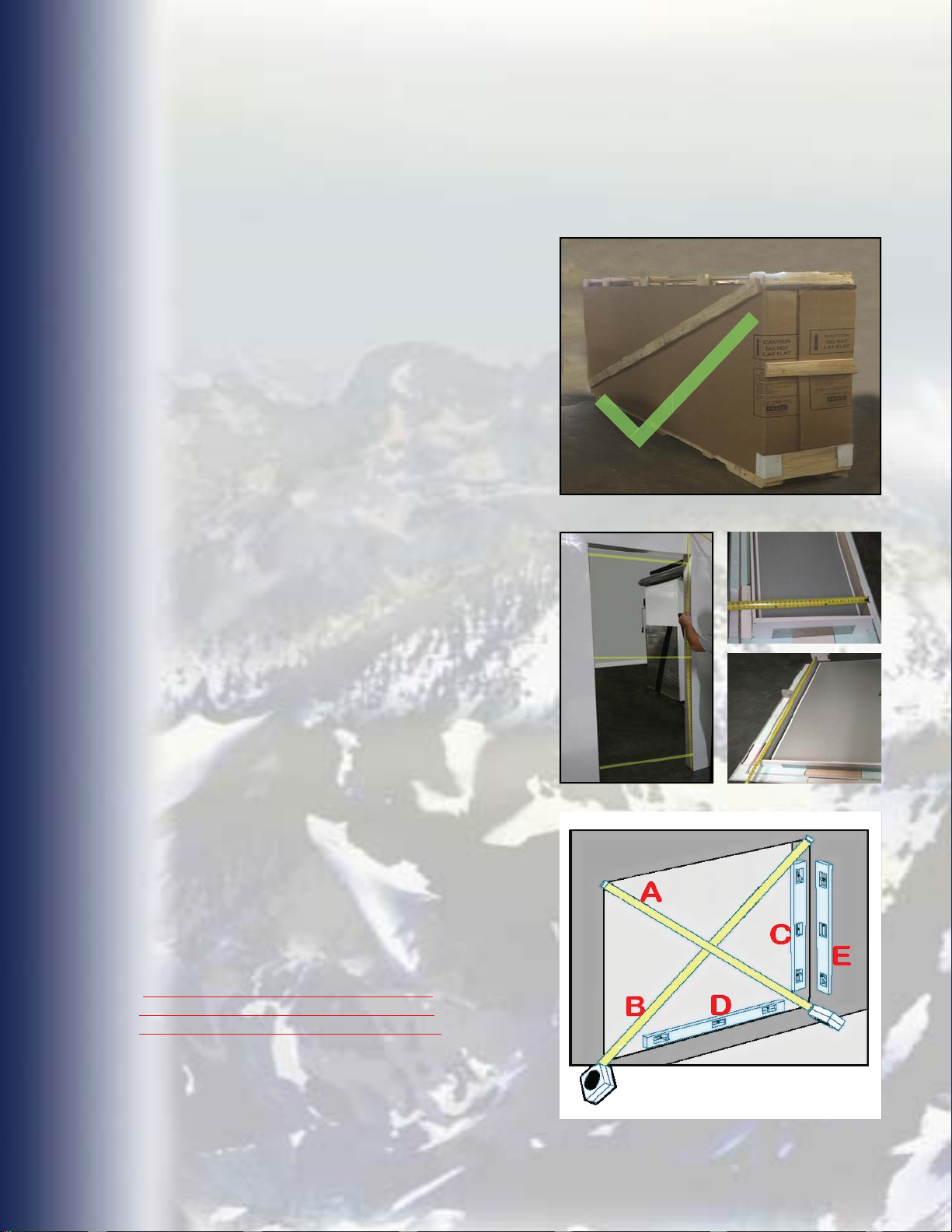
1. Check & inspect all crates for damage.
PURCHASER/RECEIVER SHOULD
NOTIFY THE FACTORY IMMEDIATELY OF
ANY DAMAGE, UNLESS DOORS WERE
SHIPPED THIRD PARTY.
2. Measure the opening for the door.
Check the packing slip attached to the
crate to verify that you have ordered
and received the correct size door
for the opening WIC X HIC. (FINISHED
OPENING)
3. Verify the finished / rough opening is
square. The (A) and (B) measurements
should be the same. Verify the rough
opening is level and plumb (C) and (D).
The maximum allowable deviation is 1/8”.
The exterior face of the box wall must be
in a single plane (E) with less than 1/8”
deviation from corner to corner.
Any walls out of plane will require that
the door frame’s casing be shimmed to
the same plane to achieve a proper seal.
33
Page 4
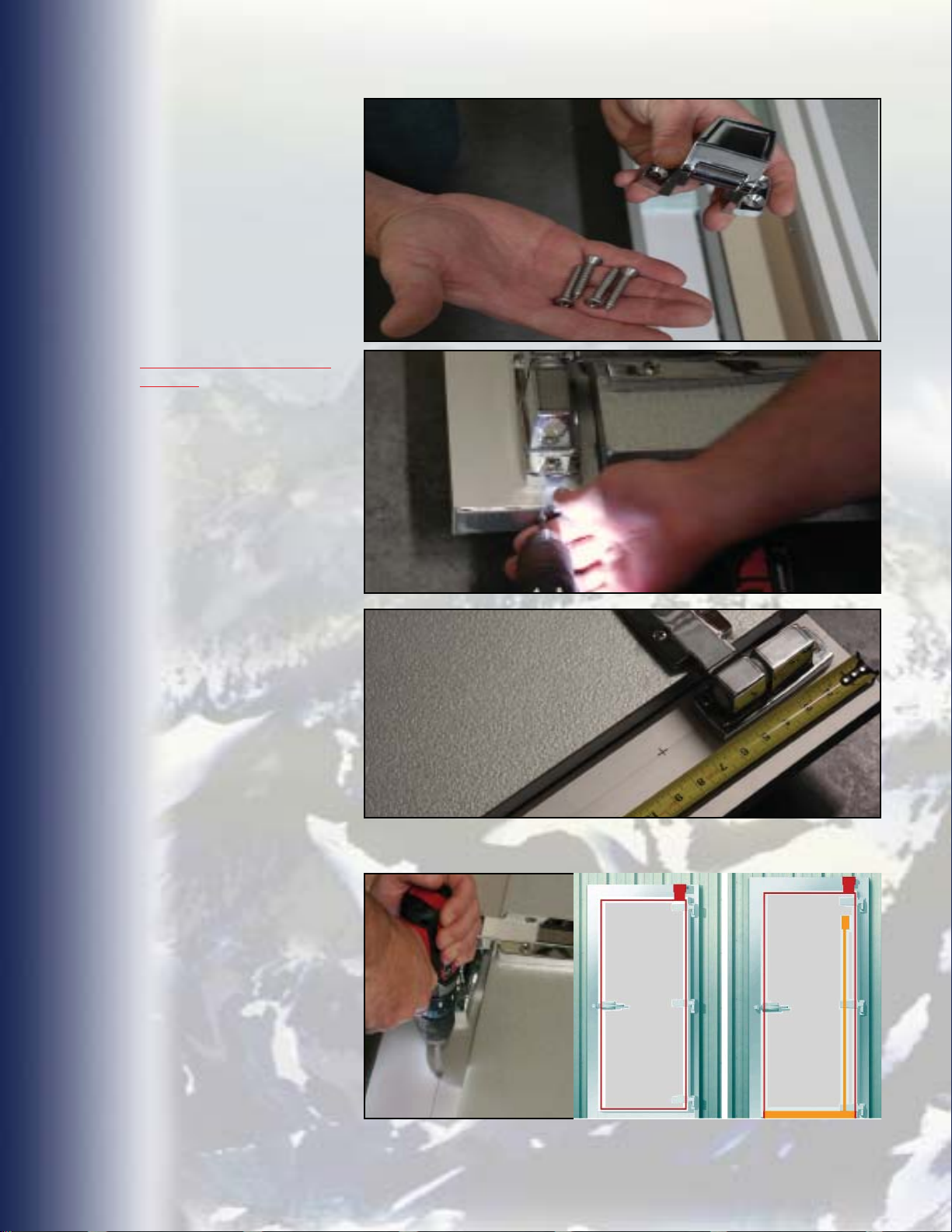
4. Lay uncrated door face
up. If assembly has a three
sided frame, remove only
the screws from the bottom
shipping strap using a #2
Philips Head. (On a swing
door with a chrome latch,
locate strike on back of
hinge side casing. With a #3
Philips Bit or Screw driver,
remove screws holding
strike assembly to blocking
without stripping heads.
Do not misplace strike or
screws!
5. It is recommended that
pilot holes be drilled in
casing frame.
6. Mark the height locations
for fasteners on your frame.
The first should be approx.
8” - 10” above the floor.
They should then be
spaced approx. 24” - 30”
apart.
Once you have marked the
height locations on your
side casings, go to each
mark:
Remove Screws & Strike from Back
of the Face Casing. DO NOT MISPLACE
STRIKE OR SCREWS!
Remove Screws From Shipping Strap
6” Wide Casings
From the
in 3 1/4” and mark.
4” Wide Casings
From the
in 1 1/4” and mark.
outer edge
outer edge
7. Using a 1/8” drill bit, drill
pilot holes at marks.
ON FREEZER DOOR
ASSEMBLIES : DO NOT
DRILL FRAME IN AREA
UNDER JUNCTION BOX!
Before drilling any holes,
check area around opening
(on exterior and interior
sides of walls) and insure
there are no obstructions,
electrical conduit or
junction boxes in way of
entire door and frame
assembly.
measure
Mark Location of Fastener
measure
Drill Out Pilot Hole
Marks, Using an
1/8” Drill Bit.
DO NOT DRILL FRAME IN AREA
UNDER JUNCTION BOX.
4
Page 5
8. Dry-fit frame assembly to
opening to insure proper fit.
9. Pull the frame back out
of the opening, remove
shipping strap and apply
a 1/2” bead of caulk
approximately 1 1/2” in
from edges, around the
inner and outer edge of the
casing.
10. Set the top of the door
and frame in position in the
opening & then push the
bottom in and up against
the box wall.
IMPORTANT NOTE:
IF THIS IS NEW
CONSTRUCTION AND
FLOORING HAS NOT
BEEN INSTALLED, YOU
MUST RAISE THE WHOLE
DOOR ASSEMBLY (FRAME
DOOR & OPTIONAL
BACK-UP CASING) THE
TOTAL THICKNESS OF
THE FINISHED FLOORING,
OR DAMAGE TO THE
DOOR ASSEMBLY & THE
FINISHED FLOOR MAY
OCCUR WHEN THE FLOOR
IS INSTALLED.
Apply Caulk
Dry Fit
Lag Bolt
Equal Clearance on Sides
11. If door assembly was
ordered with optional return
jambs, space the return
jambs in opening with
equal clearance on sides.
From the interior, shim the
head and side jambs 6”
from the corners and
at 8” intervals. Install shims
at the strike location and
at each hinge location.
Mark shim centerlines for
ease of location so the
screws (installed later)
will penetrate each shim.
Clamp the frame (and
optional back-up frame if
ordered) to the wall using
two clamps on each leg of
the frame.
Carriage Bolt
SHIM AS REQUIRED
TO KEEP EQUAL
CLEARANCE ON SIDES
55
Page 6
12. Using a rubber mallet,
tap the hinge side casing
and top casing until they
are plumb/square and
tighten clamps.
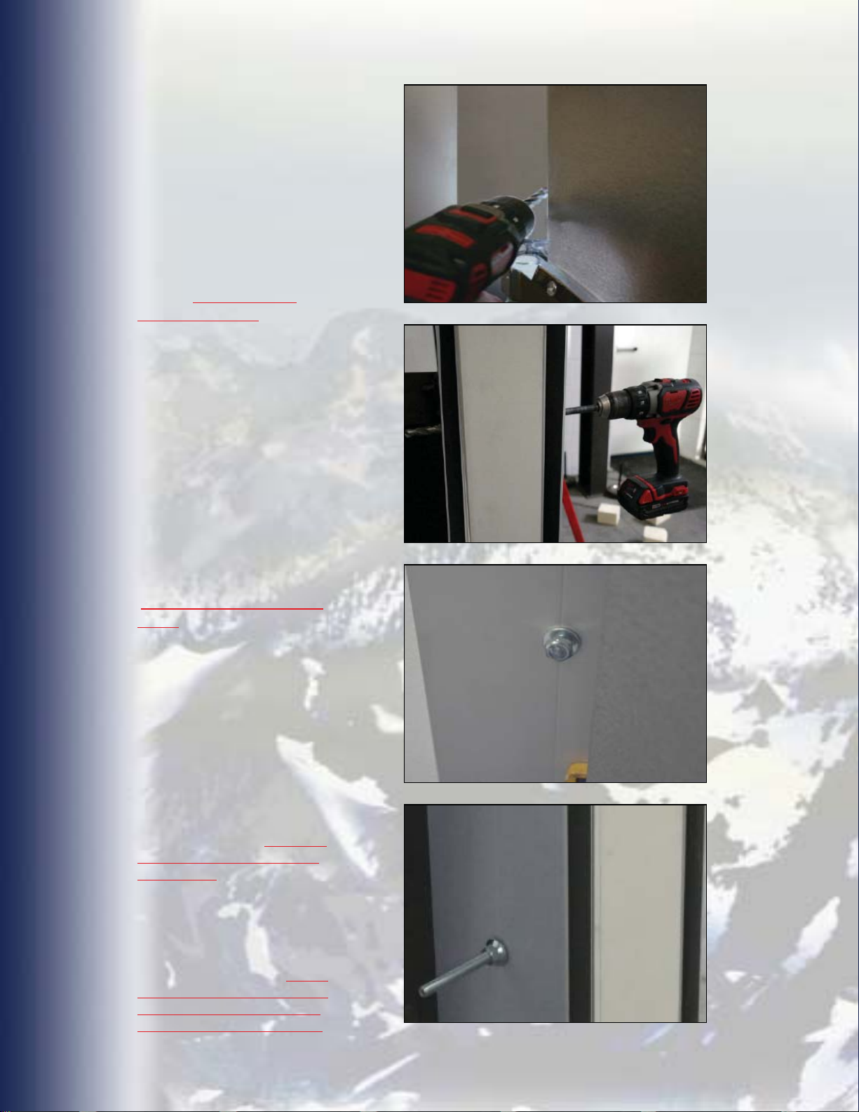
13. Using a 1/4” bit, drill
through the pilot holes on
the hinge side casing and
into box wall solid framing
for each 3/8” X 4” lag bolt
(optional). Using a 3/8” drill
bit, drill
face casing only
shaft.
Note: If door assembly
was ordered with a backup frame, using a 3/8” x
12” drill bit, drill straight
through face casing, wall
and back-up frame for 3/8”
carriage bolts installation
hardware.
After drilling out all
the fastener holes,
OPTIONAL RETURN JAMBS
WERE ORDERED ONLY!)
Use Backer Rod or
LOW EXPANSION FOAM
face frame or
for lag
(IF
ONLY, to fill void between
side of return jamb and
panel edge.
Drill into box wall solid
framing for lag bollts.
Drill straight through optional
back-up frame for carriage
bolts.
14. Insert lag bolt / carriage
bolt in top hole of the hinge
side casing/frame, check
straightness of casing/
frame and insert lag /
carriage bolt in hole located
by bottom hinge. Insert
remaing bolts on hinge
side casing in holes. Hand
tighten bolts only. DO NOT
OVER TIGHTEN BOLTS AT
THIS TIME!
15. Follow the same
procedure on the top and
strike side casings. Tighten
bolts to position door
assembly on the wall. HAND
TIGHTEN THE BOLTS ONLY!
DO NOT CUT OFF EXCESS
ON CARRIAGE BOLTS YET!
Hand tighten bolts only at
this time.
DO NOT CUT OFF EXCESS
ON CARRIAGE BOLTS YET!
6
Page 7
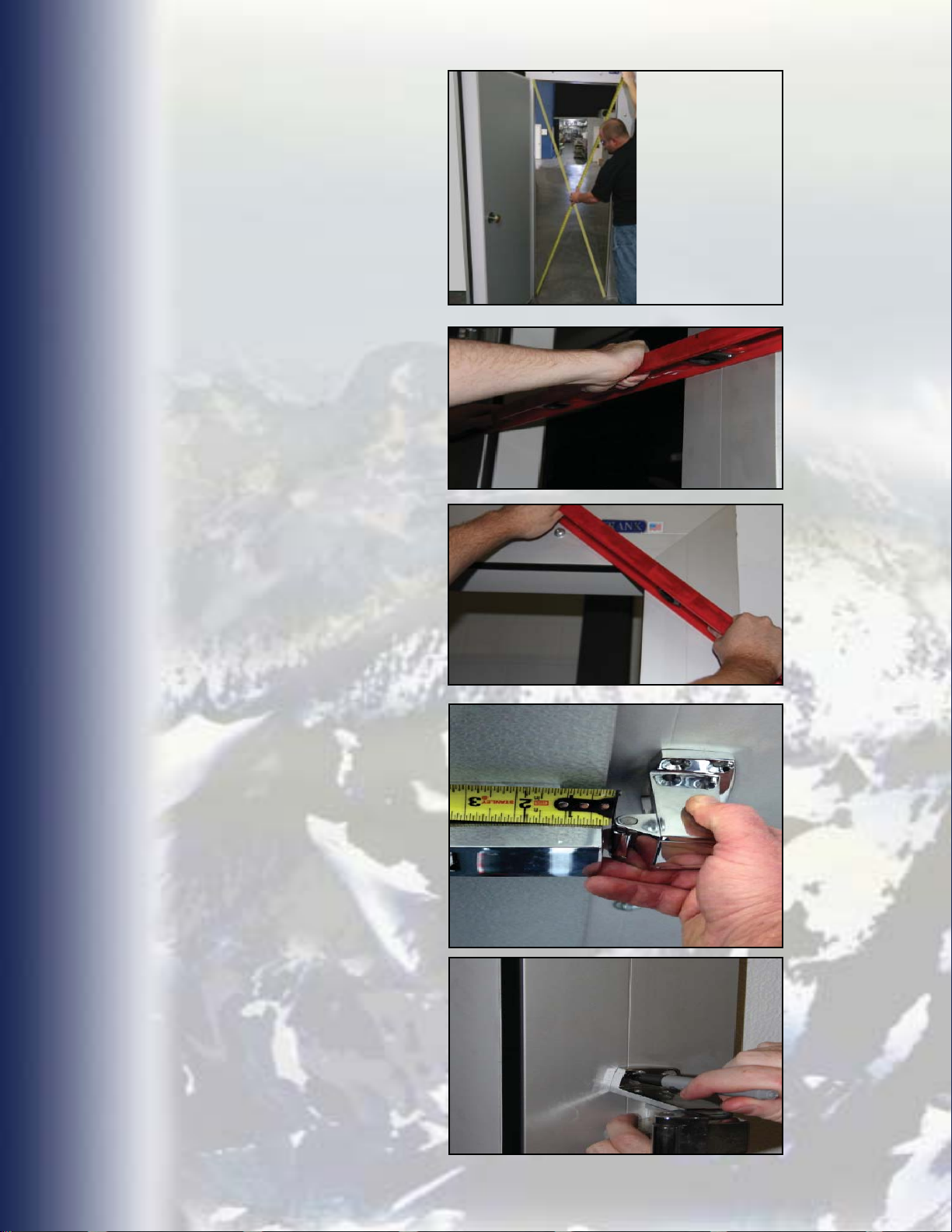
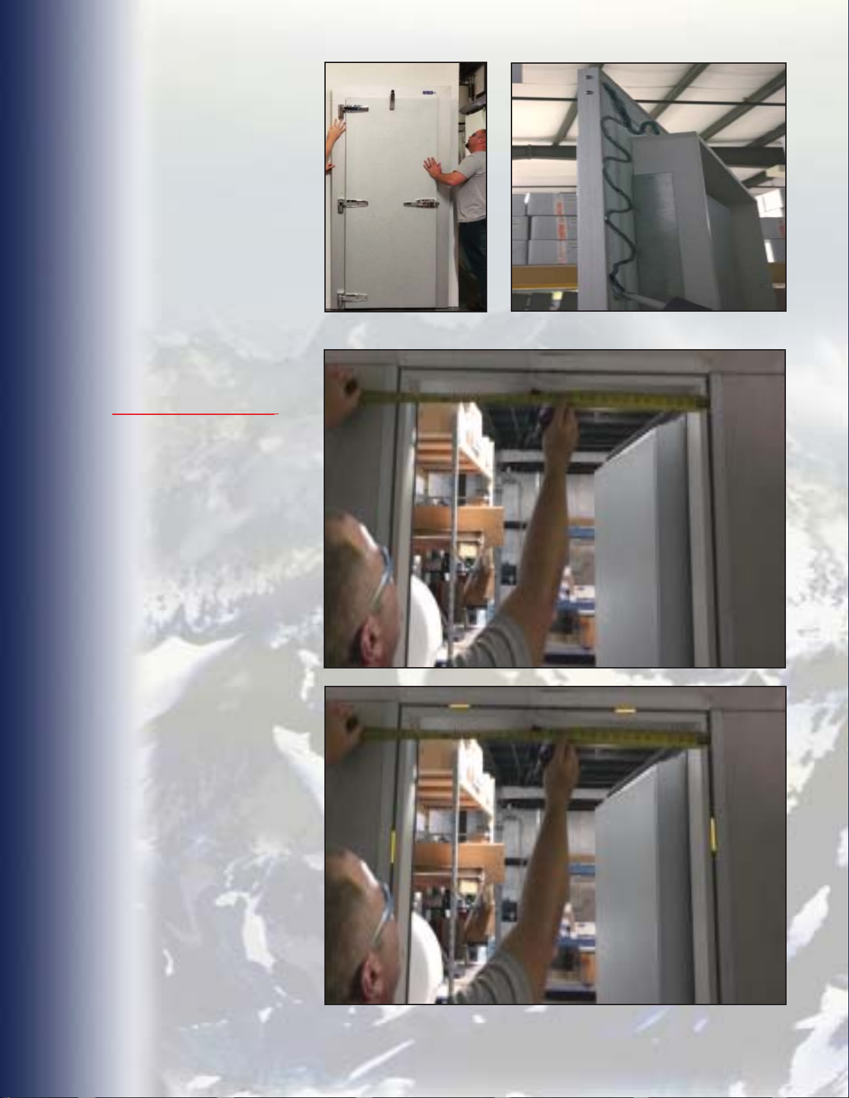
16. Check plumb position to
insure that the frame is plumb
and square. Measure the
opening diagonally to make
sure door assembly is set
square in opening.
17. Draw lag bolts / carriage
bolts snug, but do not draw
casing out of plane.
18. Smooth and clean up
any excess sealant that has
squeezed out between casing
and wall.
19. Recheck plumb position.
Measure the
opening
diagonally to
make sure
door assembly
is set square in
opening.
20. Check to ensure the casing
frame is in plane by using a
level. Lay the straight edge of
level across the face casing
frame. The straight edge of the
level must be in full, flat contact
with the face casing at various
angles. If not, loosen the lags/
carriage bolts and add shims
between the wall and the back
of the casing frame. Snug up
fasteners.
21. With door closed, align
strike assembly and mark hole
placement to mount strike.
(There should be 1/8” gap
between the between the front
edge of the roller and the latch
body.)
22. Install strike to frame with
screws supplied. Using a 7/32”
drill bit, drill only one front hole
and the opposite back hole.
Use front hole screw position
only at this time and attach
strike.
Make sure all sides of the face
casing are on the same plane.
Check plane of face casing
at various locations.
Leave an 1/8” gap
between the front edge of the
roller and the latch body.
23. The strike roller is fully
retracted and must be adjusted
out by the installer.
24. Remove the two hex head
bolts that attach the roller to
the strike base. Move roller
assembly up and relocate and
insert bolts in upper holes.
Slightly tighten bolts.
Mark mounting holes in strike.
77
Page 8
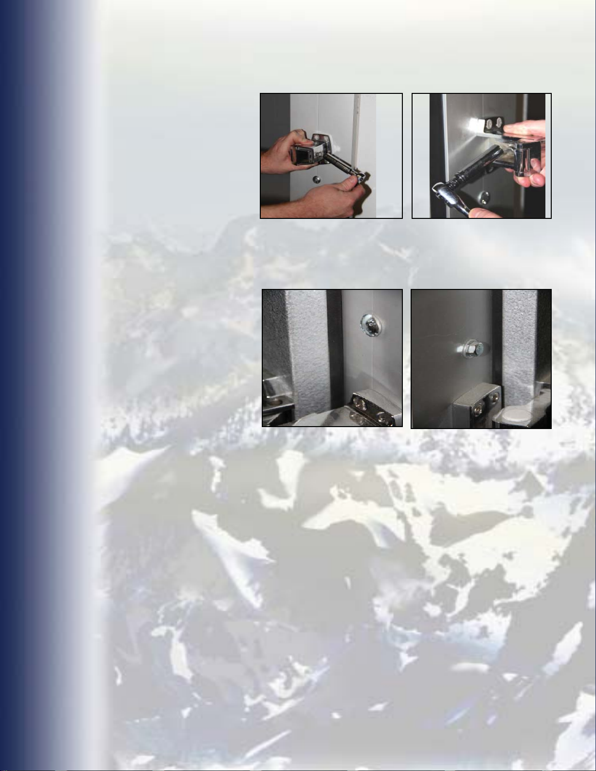
25. Close door and set
roller assembly. Use a 9/16”
socket and remove inside
and outside bolts. Slide
roller assembly section of
strike out. Insert bolt in hole
furthest away from strike
base. Set strike so door is
snug and tighten outside
bolt. On the inside of the
roller assembly insert bolt
in outer hole and tighten
bolt.
26. If gap between the
front edge of the roller
and the latch body has
been maintained to 1/8”,
open door and tighten bolt
inside strike assembly. Drill
out and install remaining
screws. Do not over tighten
screws.
27. Open and close door to
insure it operates correctly
and that the strike for the
latch is adjusted properly.
The latch should seat firmly
to hold the door closed and
tightly sealed. Adjust the
strike accordingly. Check
inside release for proper
operation.
28. With door in closed
position, check the gasket
compression at all contact
points by closing the door
against a piece of paper. If
the paper is loose and does
not drag when removed,
the door is not making
proper contact. Adjust
by shimming frame and/
or adjusting hardware as
required.
The strike roller is fully retracted and must
be adjusted out by the installer.
DO NOT OVER COMPRESS GASKET! If
the gasket is not sealing without over
compressing the gasket, the casings are
out of plane.
**NOTE: When shimming out the face casing/
frame, you shim the opposite side of the frame.
DO NOT OVER COMPRESS GASKET! Too
much pressure on the hinge side will prevent
proper contact on the latch side and cause
binding of the gasket, hard operation and/ or
damage to hinges and other components.
8
Page 9
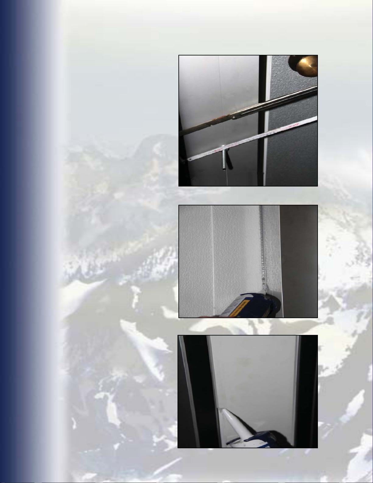
29. When the door is
sealing properly, cut
carriage bolts(if used), to
length and file off any sharp
edges.
30. Neatly run a bead of
caulk around the ENTIRE
perimeter of the frame
edge and box wall /floor.
Caulk also the entire inner
edge of frame at opening
and box wall / floor. Smooth
and clean up any excess
sealant.
CUT CARRIAGEBOLTS AT BACK UP
CASING
CAULK FULL PERIMETER
OF OUTER AND INNER
EDGE OF FACE CASING.
*If door was ordered with
back up frame, neatly run
a bead of caulk around the
ENTIRE perimeter of the
backup frame edge and
box wall /floor. Caulk the
entire inner edge of back
up frame at opening and
box wall / floor. Smooth
and clean up any excess
sealant.
CAULK FULL PERIMETER OF OUTER
AND INNER EDGE
OF OPTIONAL BACK
UP CASING FRAME.
99
Page 10

SWING DOOR OPERATION & MAINTENANCE
SCHEDULE
Our doors are manufactured to provide many years of reliable and trouble
- free operation. Doors must be installed by a
Door Contractor and as per the installation manual provided with each door
assembly. Periodic adjustments and normal maintenance are the responsibility
of the customer.
Doors not installed by a
been altered without the specified written consent of a FACTORY AUTHORIZED
REPRESENTATIVE or doors that have been damaged/abused may require more
maintenance than the recommended schedule below.
COOLER & FREEZER DOORS
DAILY:
1. SMOOTH OPERATION
2. POSITIVE SEAL
3. DAMAGE
4. LOOSE, DAMAGED OR MISSING PARTS
QUALIFIED
Cold Storage Door Contractor, or that have
QUALIFIED
Cold Storage
WEEKLY:
1. GASKETS FOR TEARS, RIPS OR ANY OTHER DAMAGE
MONTHLY:
1. ALL FASTENERS
FREEZER DOORS
DAILY:
1. HEATER FOR PROPER OPERATION (SHOULD HAVE UNINTERRUPTED &
SEPARATE POWER SUPPLY)
PLEASE MAKE ANY & ALL ADJUSTMENTS TO ENSURE SMOOTH
OPERATION & POSITIVE SEAL AS REQUIRED PER INSTALLATION
INSTRUCTIONS PROVIDED WITH EACH DOOR.
REPAIR AND/OR REPLACE ANY WORN, DAMAGED OR DEFECTIVE
PART AS SOON AS DETECTED.
10
Page 11

Warranty - The Frank Door Company warrants to the original owner of this product that the
door panel will be free of defective material and workmanship, for a period of five (5) years
and a two (2) year warranty on all other Frank Door Company manufactured components
(excluding normal wear parts), commencing with the date of shipment from the factory. Frank
Door Company warrants products or component parts used on the doors, but not manufactured
by Frank Door, to the purchaser, to the same extent that they are warranted by the original
manufacturer to Frank Door.
The warranty becomes valid upon the receipt of “Payment in Full” by Frank Door Company.
Only defects called to Frank Door Company’s attention during this period of time will be
covered under this warranty. This warranty is null and void if:
The door(s) are altered in any way without advanced written consent of the Frank Door
Company.
The door(s) are not installed within 120 days of original shipment.
Frank Door Company will not be responsible for any installation (labor) costs incurred during
replacement, or for replacement or repair of any materials subjected to excessive abuse,
misuse, or improper installation.
Frank Door will repair or replace at its discretion and at no charge, with freight prepaid (carrier
of Frank Door Company’s choice), any door or its component parts which are found defective
upon inspection by an authorized Frank Door Company representative. This provision of repair
or replacement shall be the limit of Frank Door’s responsibility under this warranty. Frank Door
Company shall not be responsible for other losses or damages claimed to be caused by any
door or door parts covered under this warranty.
No other oral or written representation made by Frank Door Company or its agents are part
of this warranty unless specifically set forth in writing by an authorized Frank Door Company
representative.
The above set forth warranty is seller’s sole warranty. Seller, makes no other warranty of any
kind whatever, expressed or implied; and all implied warranties or merchantability and fitness
for a particular purpose which exceed the aforestated obligation and hereby disclaimed by the
seller and excluded from this agreement.
Back Charge Claim Policy - The Frank Door Company strictly enforces this Warranty Back
Charge Policy. Prior to ANY warranty work being performed, the following procedures must
be followed. Frank Door reserves the right to deny ANY back charges or invoices if these
procedures are not followed. A detailed explanation of the issue(s) must be presented to
the Manager of Customer Service for review. If the claim is determined to be justifiable by
the Manager of Customer Service, the following information shall be required prior to any
expenditures or work being performed:
The Manager of Customer Service will issue a purchase order for the scope of work with a
“Not to Exceed” monetary amount for the scope of work specifically set forth in writing. Any
changes or modifications to the scope of work or the monetary value must have prior written
approval from the Manager of Customer Service.
The total liability to Frank Door Company shall be the total monetary value of the scope of work
approved in writing by the purchase order and any modifications thereof by the Manager of
Customer Service. No other oral or written representatives made by Frank Door Company or its
agents are part of this policy unless specifically set forth in writing by the Manager of Customer
Service.
1111
Page 12

Over 25 years of
quality craftsmanship
with service and support
you can count on.
TRADITIONAL SWING MANUAL
The American Standard for Cold Storage Swing Doors
As the Frank Door Company constantly strives to build the highest quality products for performance and value,
the design, specifi cations, materials, features and prices are subject to change without notice.
413 Howard Blvd., Newport, North Carolina USA 28570
www.frankdoor.com
12
 Loading...