

Frank Door TS723 Installation Manual
TS723 Power Operator Instructions
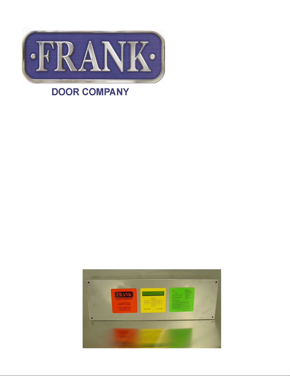
413 HOWARD BLVD.
NEWPORT, NC 28570
252.223.1112
888.833.DOOR (3667)
FAX: 252.223.1116
TS723
(Model Years 12/06 thru current)
Microprocessor Control System for three-phase drive units
The TS723 self-positioning control system is designed for three-phase motors to open
and close sliding doors and is to be used for industrial applications only. The acceleration
and deceleration of the motor is adjustable as well as the travel speed of the door. The
positions of the door are controlled by an integrated position control system (encoder). As
the drive unit is equipped with a position control system, the TS723 control system
recognizes this automatically. Both drive unit and control system are electronically
protected against damage from overload or a short circuit. All programming and
adjustments are carried out with membrane keys located on the outside of the closed
case - after all connections have been done. For safety reasons, no adjustments are
possible within the case.
http://www.frankdoor.com/TS723_PowerOperator_Instructions.htm (1 of 16)3/17/2008 8:24:17 AM

TS723 Power Operator Instructions
TECHNICAL DATA
Mains voltage 208 / 230 / 400 / 460 / 480 VAC / 1 / 60
Power consumption 4.0 amps
Output voltage (secondary) 24VDC
Power supply (secondary) max. 1020 mA
Output voltage to motor 230 VAC (3-phase)
Motor rating max. 370 watts
Dimensions HxWxD = 6 1/2" x 20 1/2" x 4 5/8"
I. Electrical Connection
I/1 Connection of external devices
Connect all wires (maximum length: 90 feet) from the external devices (operating
switches, reversing edges, etc.) to the external leads of the controller per instructions
below in Section I/2 & I/3. When using the control system together with drive units with an
electronic position control system (encoder), no additional limit switches are required. The
encoder is recognized automatically by the control system. Make sure there is a lockable
switch in the supply line to control system that will cut off the power supply completely.
Furthermore, a separate fuse must be provided on the site to protect the supply line
and the connection terminals of the control system.
I/2 Wiring connections for pull switch stations, 2-button switch, locks
Note: Pull switch stations & 2-button switches (if supplied) must be wired normally
open & in parallel. Locking device (if supplied) must be wired normally closed & in
series with reversing edge.
Connect pull switch stations to leads labeled "Pull Switch/Push Button" (Wires 1 & 2)
Connect "Open/Close" feature of 2-button switch (if supplied) to leads labeled "Pull Switch/
http://www.frankdoor.com/TS723_PowerOperator_Instructions.htm (2 of 16)3/17/2008 8:24:17 AM

TS723 Power Operator Instructions
Push Button" (Wires 1 & 2)
Connect "Partial Open" feature of 2-button switch (if supplied) to leads labeled "Partial
Open" (Wires 7 & 8)
Connect locking device (if supplied) to leads labeled "Lock/Stop"
I/3 Wiring connections for reversing edge
Plug in leads from reversing edge to connector on trailing edge side of header. On
biparting doors, there is a connector on each side of header.
I/4 Wiring connections for photocell (if applicable)
Run wires from terminals 1 & 3 (in photocell) to leads labeled "Reversing Edge" (Wires 5
& 6)
Run wires from power supply terminals (in photocell) to leads labeled "24 Volt/Aux
Power" (Wires 9 & 10. Note that wire #9 is the hot lead)
Make sure that photocell switch is set to "LIGHT"
Note: If using a photocell & reversing edge together, they MUST be wired in series
I/5 Wiring connections for radio receiver (if applicable)
Radio receiver is pre-wired in the factory. If a radio receiver is added after initial
installation:
Connect RED wire from radio receiver to lead labeled "24 Volt/Aux Power" (Wire 9)
Connect BLACK wire from radio receiver to lead labeled "24 Volt/Aux Power" (Wire 10)
Connect GRAY wires from radio receiver to leads labeled "Pull Switch/Push
Button" (Wires 1 & 2)
I/6 Wiring connections for D38 motion detector (if applicable)
#1 wire from motion detector to a 24 volt transformer
http://www.frankdoor.com/TS723_PowerOperator_Instructions.htm (3 of 16)3/17/2008 8:24:17 AM

TS723 Power Operator Instructions
#2 wire from motion detector to a 24 volt transformer
#3 wire from motion detector to lead labeled "Pull Switch/Push Button"
#4 wire from motion detector to lead labeled "Pull Switch/Push Button"
Dips on motion detector
#1 - on
#2 - off
#3 - off
#4 - on
Note: Both "Open" & "Close" Controls must be set at "Full Travel"
"Automatic Closing" must be set to "On"
Please follow manufacturer's instructions for all other motion detectors.
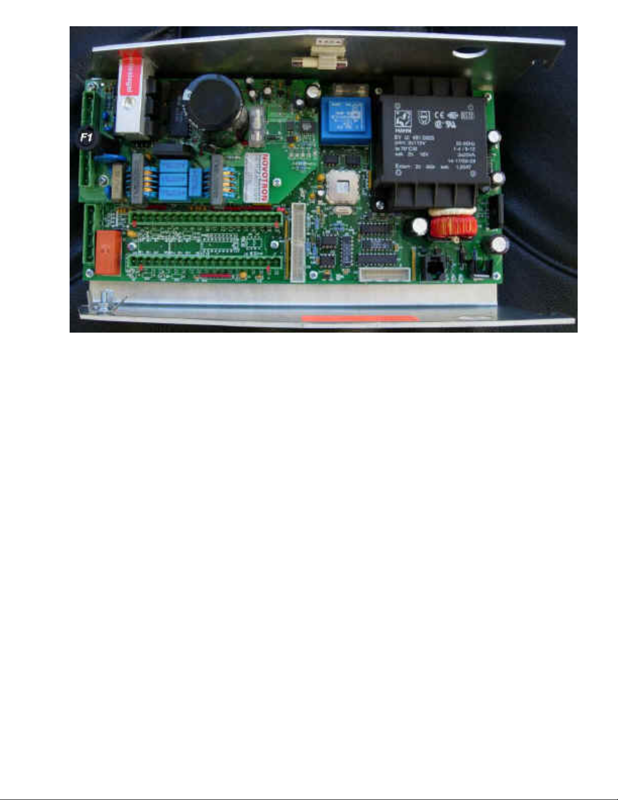
I/7 Location of fuses
FUSE F1: T 4.0 A Main fuse (time-lag fuse)
(Complete 230V AC supply)
http://www.frankdoor.com/TS723_PowerOperator_Instructions.htm (4 of 16)3/17/2008 8:24:17 AM
TS723 Power Operator Instructions
II. Adjustment/Programming
All adjustments and programming are carried out with the membrane keys and the LCD
display on the lid of the control system. On the following page, you will find the adjustment
menu with all adjustable functions and values. Please mark in the right hand column, the
values you adjusted in your control system. Detailed information on how to adjust the
speeds and the positions of the door can be found on pages 8 and 9.
WARNING: Never make any adjustments when the door is moving!
II/1 Operation
1) Switch on the mains power supply. The LCD display on the lid will show for a short
time, the number of the software update used in this control system. Afterwards, it
switches to "Find Encoder Limits Automatically - ENT". (Do not press "ENTER" at this
time. See Section II/3 Adjustment/Programming on the following page.)
2) You can choose between English, German, Franch, Italian, and Spanish (the default is
set to English).
http://www.frankdoor.com/TS723_PowerOperator_Instructions.htm (5 of 16)3/17/2008 8:24:17 AM
 Loading...