

Frank Door T1000 Service Manual
SHOCK HAZARD:
Before opening the controller, wait ve minutes for stored energy to dissipate.
Failure to do so may result in painful electrical shock causing injury and/or death
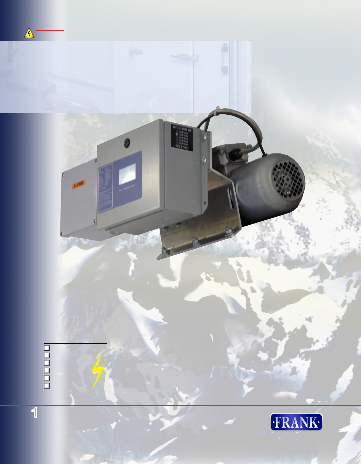
T1000
Microprocessor Control System
Troubleshooting Guide
This Unit Is Wired For:
120/1/47-63
208/1/47-63
230/1/47-63
400/1/47-63
460/1/47-63
480/1/47-63
(Fuses on Page 8)
1
www.frankdoor.com
Start-Up and
Date:_____________
Customer:_____________
Door Size:_____________
Door S/N:_____________
Controller S/N:_____________
Motor S/N:_____________
_____________
The American Standard for Cold Storage Doors
toll free (888) 833-3667 phone (252) 223-1112 fax (252) 223-1116
Frank Door Company © September 2012-100
Input Voltage 120/208/230/400/460/480 VAC
120 VAC at 16 Amps Max
240 VAC at 8.5 Amps Max
480 VAC at 4.3 Amps Max
Motor Output: 230V 60Hz 3Ph
Motor Load: 370 Watt Max
Technical Data
47-63 Hz, 1Ph
Aux. Voltage: 24 VDC
Aux. Load: 1 Amp Max.
Enclosure NEMA 4

THE BEST IN COLD STORAGE DOOR
AUTOMATION
The T1000 microprocessor-based operator
provides unprecedented control and exibility
in a variety of cold storage applications.
At the push of a button, the T1000 operator
sets its own limits and offers multiple points of
control. Once encoded, the system will never
forget its limits. The microprocessor controls
door position, opening and closing speeds,
partial openings and time-delay closing.
It is fully integrated and does not require
maintenance-prone torque limiters or limit
switches, eliminating constant maintenance
and safety issues.
The system assesses surrounding climate to
intelligently maintain component temperature
enabling applications below 0°C (32 °F). The
system has been designed to handle frequent
openings and closings in the toughest
conditions.
The front-end power factor corrector (PFC)
automatically transforms any voltage from 100
VAC to 230 VAC. A transformer is available
for higher voltages. This conguration allows
for safe installation in facilities where voltage
can uctuate.
Additional features include soft start and stop,
a touch pad display, password protection, a
cycle counter, electronic overload protection
and sophisticated internal diagnostics. There
are no internal control system options to add.
Frank Door Company offers the best drive system
available backed by unprecedented technical
support. Technical support for the system is
available Monday - Friday, 8am - 5pm EST.
2
www.frankdoor.com
The American Standard for Cold Storage Doors
toll free (888) 833-3667 phone (252) 223-1112 fax (252) 223-1116
Frank Door Company © September 2012-100
START-UP ELECTRICAL CONNECTIONS
A/1 Connection of External Devices
Connect all wires from the external devices (loop detectors, pull cords, push buttons, motion detectors,
etc.) to the external leads of the controller per instructions below in Section A/2 & A/9 (leads are located
in service box mounted to controller labeled “24 volts”). This drive system utilizes an encoder, no
additional limit switches are required. The encoder is recognized automatically by the control system.
Make sure there is a lockable switch in the supply line to control the system that will cut off the power
supply completely. Furthermore, a separate fuse must be provided on the site to protect the
supply line and the connection terminals of the control system.
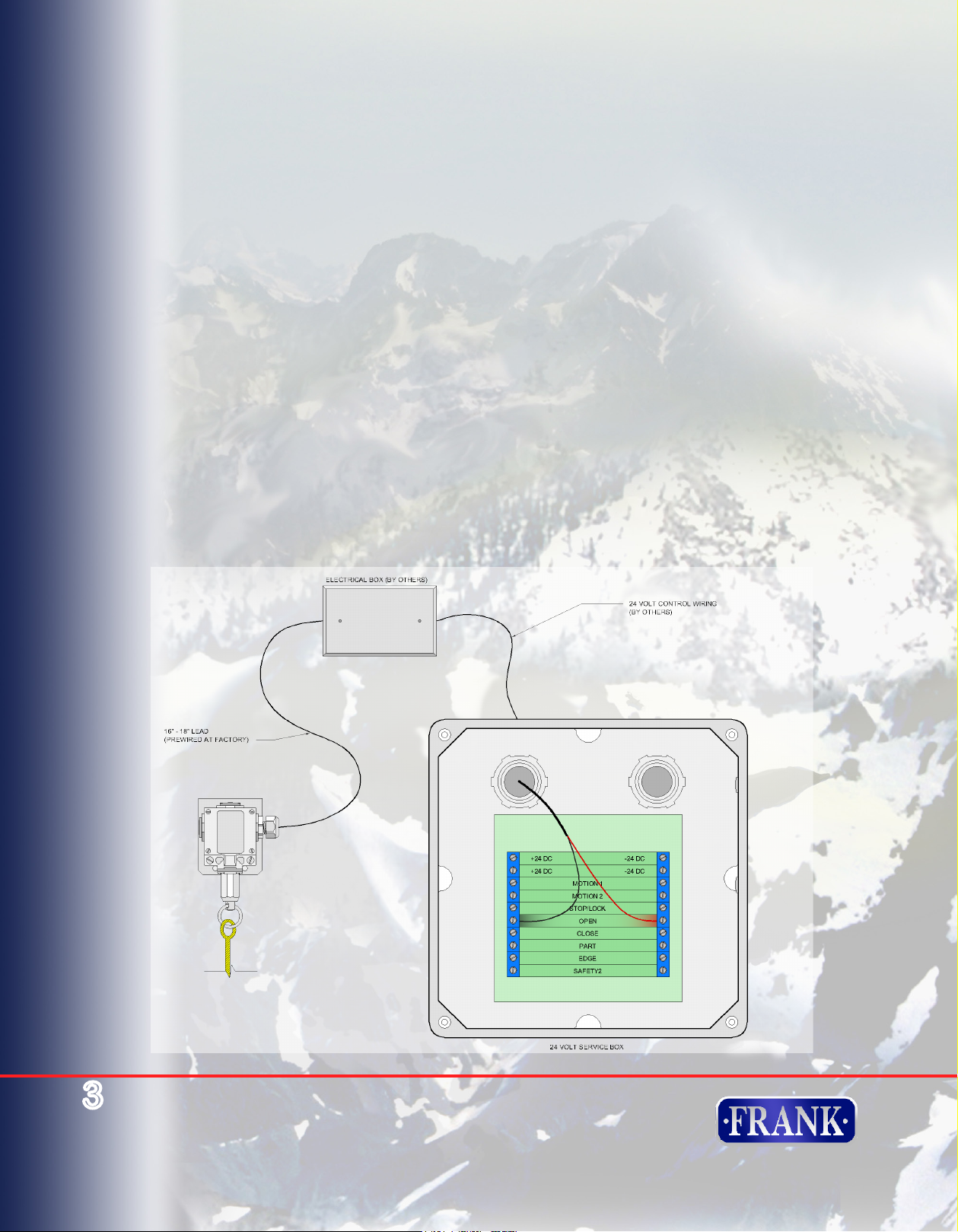
A/2 Wiring Connections for Pull Cord
Note: Pull switch stations & 2-button switches (if supplied) must be wired normally open & in
parallel.
1) Mount pull cord switch at desired location
2) Mount electrical box near pull cord switch
3) Run pre-wired lead into electrical box
4) Connect pre-wired lead to 24 volt control wiring inside electrical box
5) Run low voltage (24v) control wire from electrical box to 24 volt service box
6) Run red wire to open right bus
7) Run black wire to open left bus
3
www.frankdoor.com
The American Standard for Cold Storage Doors
toll free (888) 833-3667 phone (252) 223-1112 fax (252) 223-1116
Frank Door Company © September 2012-100
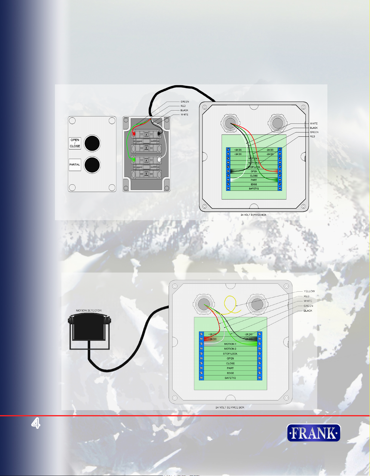
A/3 Wiring Connections for Pull Switch Stations, 2-button switch
Note: Pull switch stations & 2-button switches (if supplied) must be wired normally open & in parallel.
Connect pull switch stations to terminals labeled “OPEN”
Connect “Open/Close” feature of 2-button switch (if supplied) to terminals labeled “OPEN”
Connect “Partial Open” feature of 2-button switch (if supplied) to terminals labeled “PARTIAL OPEN”
A/4 Wiring Connections for Motion Detector (if supplied)
Connect RED to +24VDC left bus
Connect BLACK to -24VDC right bus
Connect WHITE to Motion 1 left bus
Connect GREEN to Motion 1 right bus
If using 2 motion detectors, wire extra WHITE and GREEN wire to Motion 2
4
www.frankdoor.com
The American Standard for Cold Storage Doors
toll free (888) 833-3667 phone (252) 223-1112 fax (252) 223-1116
Frank Door Company © September 2012-100

A/5 Wiring Connections for Radio Receiver (if supplied)
Radio receiver is pre-wired in the factory. If a radio receiver is added after initial installation:
Connect RED wire from radio receiver to terminal labeled “+24 VDC” on left bus
Connect BLACK wire from radio receiver to terminal labeled “-24 VDC” on right bus
Connect GRAY wires from radio receiver to terminals labeled “OPEN”
A/6 Hasp Lock
Connect BLACK wire from Hasp Lock to terminal labeled “Stop/Lock” on right bus
Connect RED wire from Hasp Lock to terminal labeled “Edge” on right bus
Connect WHITE wires from Hasp Lock to terminal labeled “Edge” on left bus
5
www.frankdoor.com
The American Standard for Cold Storage Doors
toll free (888) 833-3667 phone (252) 223-1112 fax (252) 223-1116
Frank Door Company © September 2012-100
 Loading...