

Foxconn NanoPC nT-i2000 Series User Manual

nT-i2000 series NanoPC
User’s Manual
Trademark:
All trademarks are the property of their respective owners.
Version:
User’s Manual V1.1 for nT-i2000 series NanoPC.
Symbol description:
Caution : refers to important information that can help you to use NanoPC bet-
ter, and tells you how to avoid problems.
Warning: indicating a potential risk of hardware damage or physical injury may
exist.
WEEE:
The use of this symbol indicates that this product may not be treated as household
waste. By ensuring this product is disposed of correctly, you will help prevent potential
negative consequences for the environment and human health, which could other-
wise be caused by inappropriate waste handling of this product. For more detailed
information about recycling of this product, please contact your local city ofce, your
household waste disposal service or the shop where you purchased this product.
© All rights reserved.
All trade names are registered trademarks of respective manufacturers listed.
All images are for reference only, please refer to the physical product for specic features.
CAUTION
RISK OF EXPLOSION IF BATTERY IS REPLACED
BY AN INCORRECT TYPE
DISPOSE OF USED BATTERIES ACCORDING
TO THE INSTRUCTIONS
W
A
R
N
I
N
G
!
CAUTION
!

Before using this product, please read the below safety notice carefully,
this will help to extend the product’s lifecycle, and work normally.
■ When NanoPC is working, please make sure its ventilation system is
working.
■ The power adapter is dissipating heat during normal use, please be sure
not to cover it and keep it away from your body to prevent discomfort or
injury by heat exposure.
■ Please use the power adapter that comes with the product’s package,
wrong power adapter may damage your device.
■ Make sure all the peripherals are properly connected before using Na-
noPC.
■ This product should only be used in an environment with ambient tem-
peratures between 0◦C and 40◦C.
■ Always shut down the computer before installing or uninstalling the pe-
ripheral which does not support hot plug.
■ Disconnect all peripherals before servicing or disassembling this equip-
ment.
■ Please do not disassemble this product by yourself, any disassembly not
approved by the original manufacturer may result in malfunction, and void
warranty.
■ Risk of explosion if battery is replaced by an incorrect type, please dis-
pose of used batteries according to the instructions.
CAUTION
!
Safety Notice :

TABLE OF CONTENTS
Chapter 1 Introduction of NanoPC
Top View ...................................................................................................2
Front Side View ........................................................................................2
Back Side View ........................................................................................3
Bottom View .............................................................................................3
Chapter 2 Placement and connection of NanoPC
Placement of NanoPC
On the Desk .........................................................................................5
On the Display Back .............................................................................5
Connection of NanoPC
Connect the Monitor .............................................................................7
Connect the USB Devices ....................................................................7
Connect the Network Cable .................................................................7
Connect the Power Cord ......................................................................8
Chapter 3 BIOS Setup
Enter BIOS Setup ...................................................................................10
Main .......................................................................................................11
Advanced ...............................................................................................12
Power .....................................................................................................15
Security ..................................................................................................17
BootOptions............................................................................................18
Save & Exit .............................................................................................19
Chapter 4 Install Windows OS
Install Windows 7/8 ................................................................................22
Install Drivers in Windows 7/8 ................................................................26
Chapter 5 Utility
FOX WinFlash
Local Update ......................................................................................28
About & Help.......................................................................................30
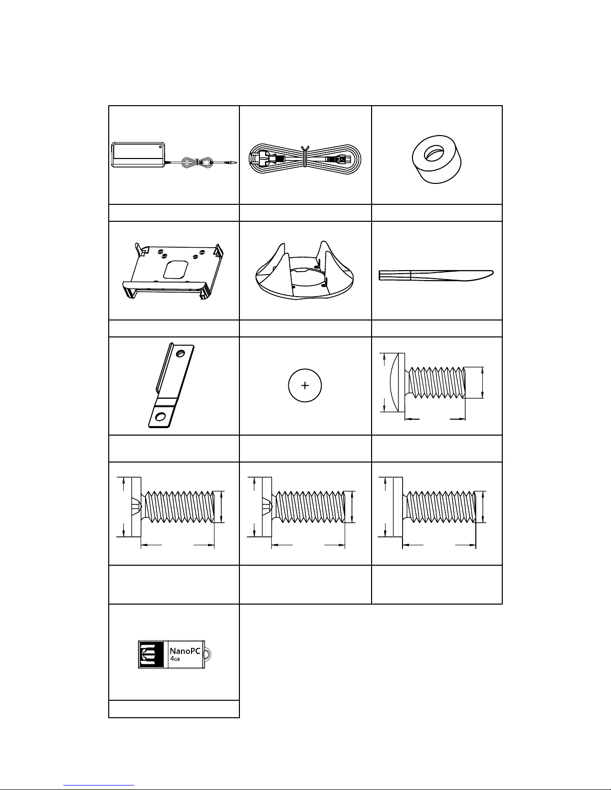
Accessory List
Thanks for choosing our products. Please check the accessories listed below. If there is anything broken or lost, please contact with your distributors as soon as possible.
Power Adapter Power Cord Magnet Rubber Foot
Vesa Mount Seatbase Opening Tool
Mini PCIe Half Card Support Screw Cover
Screw for VESA Mounting
(M8.0X9.7mm)(4X)
Screw for HDD Support Bracket
(M:4.7X2.85mm)(4X)
Screw for Half MiniPCI Card
(M:4.4X2.85mm)(1X)
Screw for Half MiniPCI Half
Card Support Bracket
(M:4.4X4.85mm)(1X)
USB Flash Disk
8.00mm
9.70mm
3.90mm
4.70mm
2.85mm
2.92mm
4.40mm
4.85mm
2.43mm
4.40mm
2.85mm
2.42mm

This chapter introduces NanoPC’s outlook :
■ Top View
■ Front Side View
■ Back Side View
■ Bottom View
1
2
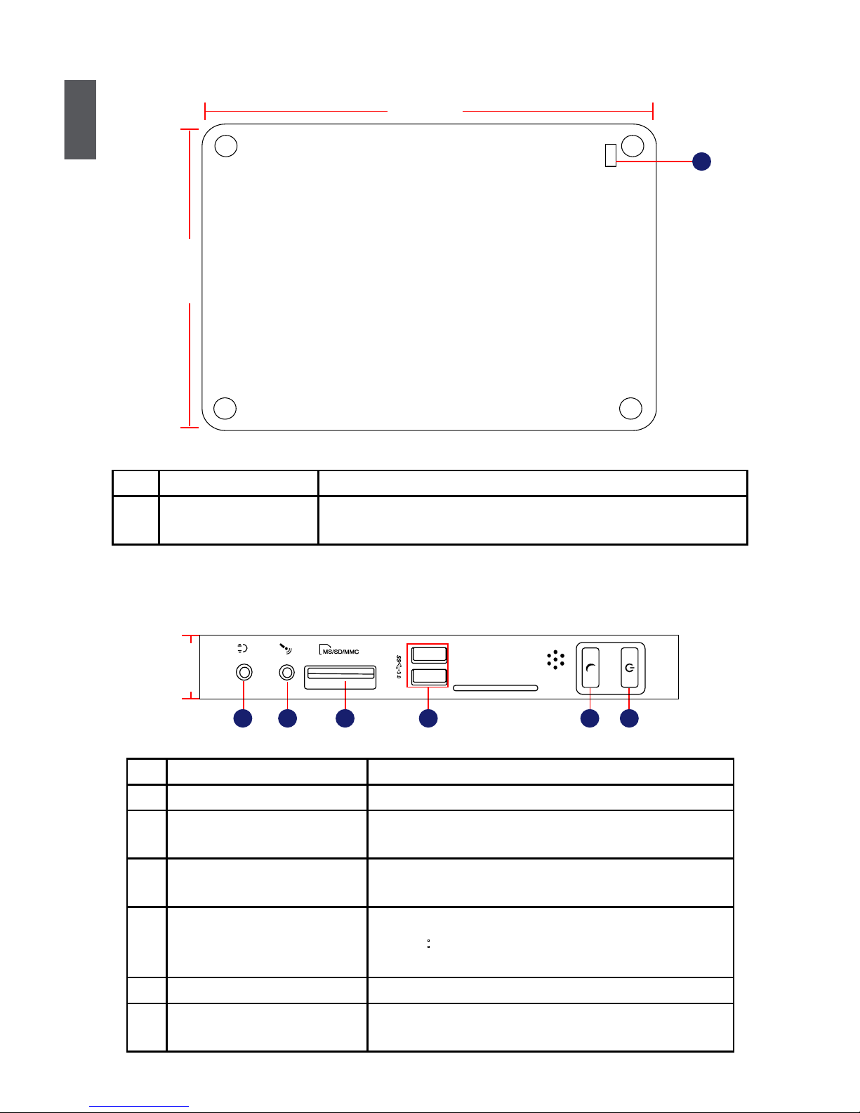
1-1 Top View
1-2 Front Side View
1
(190mm)
7.5in
5.3in
(135mm)
No. Name Description
1 Kensington Lock Attach a Kensington security system or a compatible lock to
secure your NanoPC
24mm
1
2
3 64 5
No. Name Description
1 Headphone Port Connects to a headphone
2
Microphone In and S/PDIF In
Port
Connects to a microphone or playback devices with
optical connectors(3.5mm jack)
3 Multi-Function Card Reader Support SD/SDHC/SDXC/MS/MS Pro/MMC memory
cards
4 USB 3.0 Ports Connect to USB devices
Caution
:Before using it, you need to install the “AS-
Media USB3.0 driver” in the Driver CD.
5 Suspend Button Enter suspend mode in operating system
6 Power Button with
Integrated LED Indicator
Turning the power on/off, Indicates system states
1
3
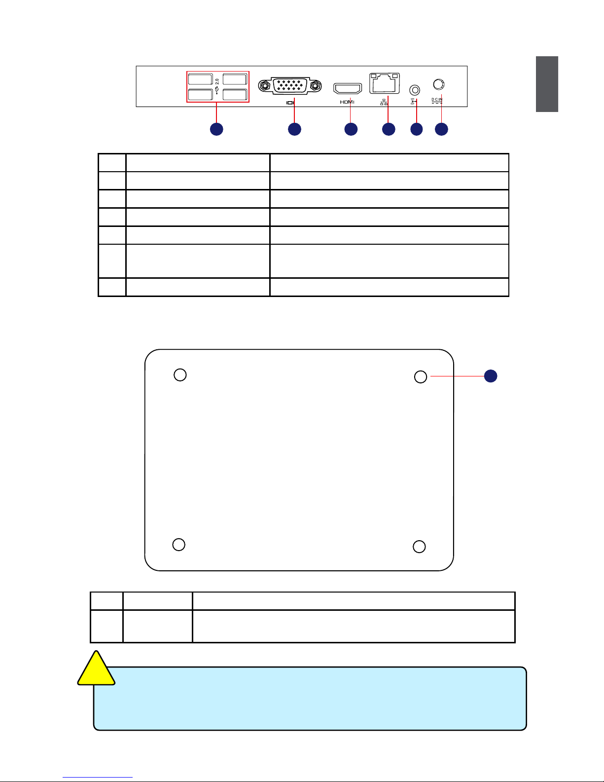
1-3 Back Side View
1-4 Bottom View
There are four Magnet-Metal-Feet in the package. Just align them to the sheet metal
on the bottom, then they can magnetize the NanoPC easily. The feet can seat and
protect NanoPC when it is placed on the tabletop.
CAUTION
!
No. Name Description
1 Sheet Metal NETDVD(optional accessory) or Magnet-Metal-Feet can magnetize
them to seat rmly
1
No. Name Description
1 USB 2.0 Ports Connects to USB devices
2 Display Output Port (VGA) Connects to display device
3 HDMI Port Connects to HDMI audio and video
4 Network Port Standard RJ-45 network port
5
Line Out and S/PDIF Out Port
Connects to powered analog speakers or record-
ing devices with optical connectors(3.5mm jack)
6 Power Input Port Connects to the power adapter
4
3 6521
In this chapter, the placement and the connection of some neces-
sary peripherals will be introduced.
This chapter includes the following information:
■ Placement of NanoPC
■ Connection of NanoPC

2
5
2-1 Placement of NanoPC
1. On the Desk
1.1. You can install your NanoPC in the Seatbase like the right image.
1.2. If there is enough space on your desk, you can simply put your
NanoPC on the tabletop as shown below.
2. On the Display Back
This is the best space-saving way.
2.1. Use four screws to fasten the Vesa Mount onto the display back.
To install this Vesa Mount, your display must follow VESA75/VESA100 standard. The
two groups of holes on your display have different space between, and they help you
easily fasten the Vesa Mount onto your display.
CAUTION
!
2
6
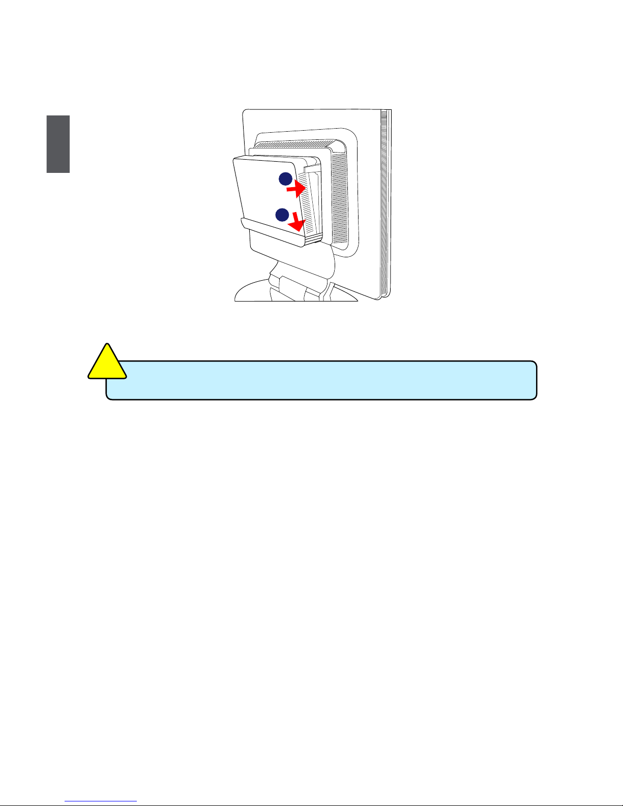
2.2. Fit the NanoPC into the Vesa Mount with power button locating at the top for easy touch.
Lift up the NanoPC straightly to take it out.
CAUTION
!
2
1
 Loading...