

Page 1
Easy Installation Guide
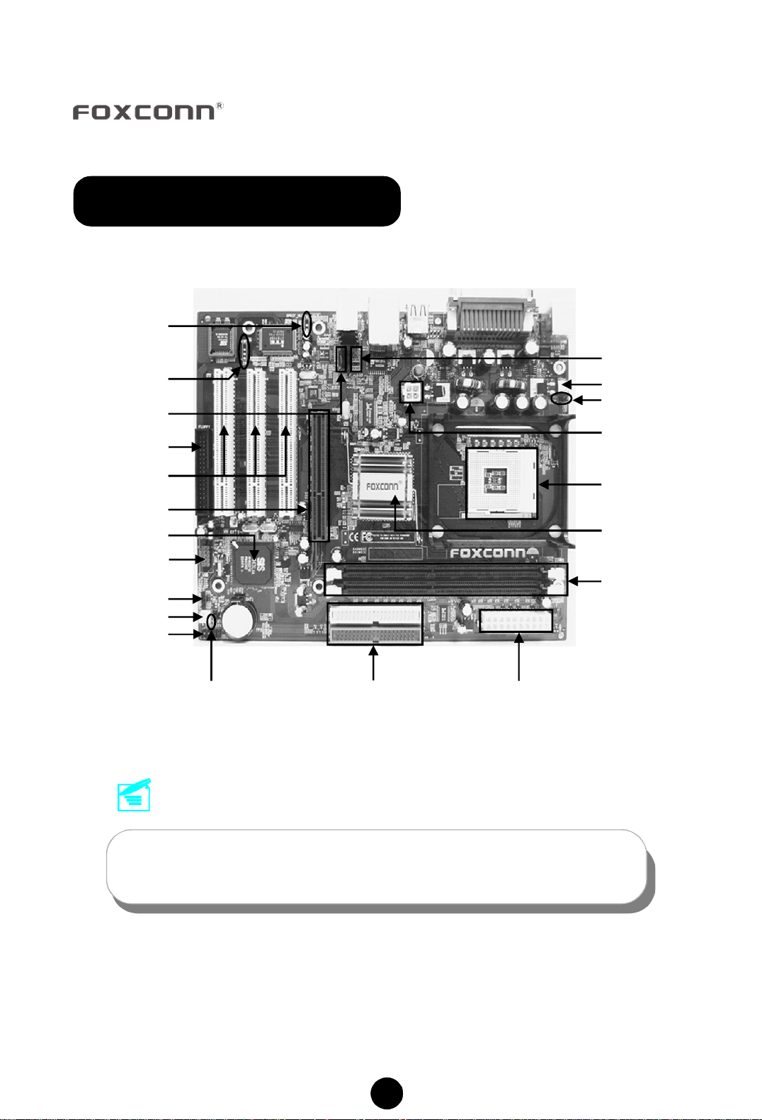
661MX Motherboard Layout
SPDIF_OUT
Connector (optional)
IrDA Connector
(optional)
CD-IN Connector
FDD Connector
PCI Expansion Slots
8X AGP Slot
SiS 963L Chipset
USB 2.0 Connector
Speaker Connector
SYSFAN Connector
Front Panel Connector
Clear
CMOS Jumper
ATA 66/100/133
IDE Connectors
Front Audio Connector
CPU FAN Connector
CPU Model Selection
Jumper
12V ATX Power
Connector
478-pinCPU Socket
SiS 661 Chipset
184-pin DIMM Slots
ATX Power
Connector
Remark:
The above motherboard layout is provided for reference only;
please refer to the physical motherboard.
P/N: 91-185-661-M3-0E
1
Page 2
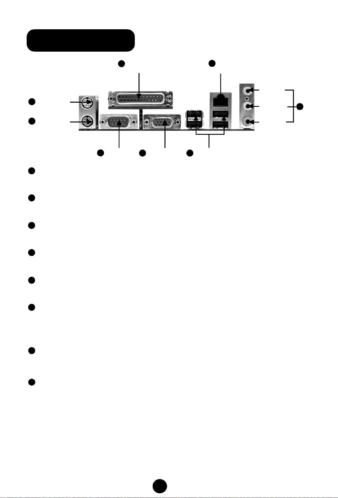
661MX Rear Panel
PS/2 Mouse
1
Connector
PS/2 Keyboard
2
Connector
1
PS/2 Mouse Connector
Serial Port
3
(COM1)
Parallel Port
4
(Printer Port)
5
VGA Port
(optional)
USB 2.0 Ports
6
7
LAN Port
(optional)
This green 6-pin connector is for a PS/2 mouse.
2
PS/2 Keyboard Connector
This purple 6-pin connector is for a PS/2 keyboard.
3
Serial Port (COM1)
This 9-pin COM1 port is for pointing devices or other serial devices.
Line-in jack
Line-out jack
Microphone
jack
8
4
Parallel Port (Printer Port)
This 25-pin port connects a parallel printer, a scanner, or other devices.
5
VGA Port (optional)
The VGA port is for output to a VGA-compatible device.
6
USB 2.0 Ports
These four Universal Serial Bus (USB) ports are available for connecting USB 2.0
devices.
7
LAN Port (optional)
This port allows connection to a Local Area Network (LAN) through a network hub.
8
Line-in jack, Line-out jack, Microphone jack
Use the three audio ports to connect audio devices. The Line-in jack is for a tape
player or other audio sources. The Line-out jack is for a headphone or a speaker.
The Microphone jack is for a microphone. In 6-Channel mode, the function of the
three jacks becomes Rear Speaker Out, Front Speaker Out and Center/Subwoofer
Speaker respectively.
2
Page 3

Accessory Checklist
Thanks for your purchasing Foxconn’s 661MX series motherboard. Please care-
fully check the package; if there are any missing or damaged items, contact your
distributor as soon as possible.
v661MX motherboard (x1)
vFoxconn Utility CD (x1)
vEasy Installation Guide (x1)
vIDE Ribbon cable (x1)
vFDD Ribbon cable (x1)
vI/O Shield (x1)
CPU/ Memory Support Features
CPU:
vSupports Intel® Pentium ®4 socket 478 (Willamette/Northwood/Prescott) pro-
cessors
vSupports Intel® Celeron ® socket 478 (Willamette/Northwood) processors
vSupports FSB at 400MHz/533MHz
vOverclock to 800MHz
Memory:
vTwo 184-pin DIMM slots
vSupports 266/333/400MHz Single Channel DDR DRAM interface
vSupports 128/256/512/1024 Mb memory technology up to 2.0GB
vSupports unbuffered non-ECC RAM
3
Page 4

1. Clear CMOS Jumper: CLS_CMOS
You can clear CMOS to restore default system setting. To clear the CMOS, follow
the procedures described below.
1. Turn off the system and unplug the AC power.
2. Remove ATX power cable from PWR1 connector.
3. Short pins 1 and 2 on this jumper.
4. Return the jumper to the normal setting by locking pins 2 and 3 together with
the jumper cap.
5. Turn the system on. The BIOS is returned to the default settings.
1
Clear CMOS
1
Normal
(default)
CLS_CMOS
2. CPU Model Selection Jumper: J2
J2 is OPEN at default, which supports the Prescott and Northwood CPU. If J2 is
set as SHORT, it supports the Willamette CPU.
SHORT
OPEN
(Default)
1
1
2
2
J2
4
Page 5

3. CPU FAN & FAN1
Plug the CPU cooling fan cable into the 3-pin CPU FAN power supply on the
motherboard. Connect the case cooling fan connector to FAN1.
SENSE 1
+12V
GND
CPU FAN
GND
+12V
1
FAN1
SENSE
4. Front Audio Connector
The audio interface provides two kinds of audio output choices: the Front Audio,
the Rear Audio. Their priority is sequenced from high to low (Front Audio to Rear
Audio). If headphones are plugged into the front panel of the chassis (using the
Front Audio), then the Line-out (Rear Audio) on the rear panel will not work. If you
do not want to use the Front Audio, pin 5 and 6, pin 9 and 10 must be SHORT, and
then the signal will be sent to the rear audio port.
1
2
MIC_IN
MIC_PWR
AUD_OUT_R AUD_RET_R
AUD_OUT_L AUD_RET_L
9 10
MIC_GND
+5VA
EmptyNC
F_ AUDIO
5
Page 6

5. CD_IN Connector
CD_IN is Sony standard CD audio connector, it can be connected to a CD-ROM
drive through a CD audio cable.
1
CD_L
GND
CD_R
CD_IN
6. Front Panel Connector
Attach the power LED, IDE LED, reset switch and power switch connectors to the
corresponding pins.
PLED
PWRBTN#
- +
1
IDE_LED
- +
RESET
NC
FP1
6
Page 7

7. Speaker Connector
The speaker connector is used to connect the speaker of the chassis.
1
SPK(pull high)
Empty
NC
SPKJ
SPEAKER
8. SPDIF Out Connector (optional)
The SPDIF output connector is capable of providing digital audio to external
speakers, or compressed AC3 data to an external Dolby digital decoder.
1
+5V
Empty
SPDIF_OUT
GND
SPDIF_OUT
7
Page 8

9. USB Connector
The USB connector is available for additional USB port if the USB ports on the rear
panel are inadequate. Compared to traditional USB 1.1 with the speed of 12Mbps,
USB 2.0 has a fancy speed up to 480Mbps, which allows faster Internet connection,
interactive gaming, and simultaneous running of high-speed peripherals.
1
VCC
D0-
D0+
GND
Empty
F_USB
VCC
D1-
D1+
GND
NC
10. IrDA Connector (optional)
This header supports wireless transmitting and receiving devices. Before using
this function, Configure the settings of IR mode from the “Integrated Peripherals”
section of the CMOS Setup Utility.
+5V
Empty
IRRX
GND
IRTX
1
IR
8
Page 9

11. 6-channel Audio Effects
The motherboard is equipped with the CODEC ALC655 chip, which provides supp-
ort for 6-channel audio output, including 2 front, 2 rear, 1 center and 1 subwoofer
channel. ALC655 allows the board to attach 4 or 6 speakers for a better surround
sound effect. To apply this function, you have to install the audio driver in utility CD as
well as an audio application supporting 6-channel. The illustration shown below
represents the standard location of all speakers in 6-channel sound track. Connect
the front speaker to the green audio output; connect the surround sound speaker to
the blue audio output and connect the center speaker/subwoofer to the red microphone
output.
Blue
Green
Center
Red
Rear Left
Front Left Front Right
Rear Right
Subwoofer
12. Power on and Load Optimized Defaults
After you finish the setting of jumpers and connect correct cables, power on the
system and press <Del> during POST (Power On Self Test) to enter the BIOS Setup
Utility. Choose “Load Optimized Defaults” for recommended optimal performance.
Select this option
and press <Enter>.
9
Page 10

13. Foxconn Utility CD
This motherboard comes with one Utility CD. To begin using the CD, simply insert
the CD disc into the CD-ROM drive. The CD will automatically bring up the main
menu screen. Click “Install Driver”, then click the relevant buttons to install the IDE
Driver, AGP Driver, VGA Driver, DirectX 9.0b, USB2.0 Driver, Audio Driver and LAN
Driver from this CD.
Follow the screen
order to install the
motherboard drivers
10
 Loading...