

Page 1

Statement:
This manual is the intellectual property of Foxconn, Inc. Although the
information in this manual may be changed or modified at any time,
Foxconn does not obligate itself to inform the user of these changes.
Trademark:
All trademarks are the property of their respective owners.
Version:
User Manual V1.0 in English for 6497MC series motherboard
P/N: 91-181649MC0E-00
Symbol description:
Note: refers to important information that can help you to use motherboard
` better.
Attention: indicates that it may damage hardware or cause data loss,
and tells you how to avoid such problems.
Warning: means that a potential risk of property damage or physical
injury exists.
More information:
If you want more information about our products, please visit Foxconn’s
website: http://www.foxconnchannel.com
PDF 文件使用 "pdfFactory" 试用版本创建 www.fineprint.com.cn
Page 2

Declaration of conformity
HON HAI PRECISION INDUSTRY COMPANY LTD
66 , CHUNG SHAN RD., TU-CHENG INDUSTRIAL DISTRICT,
TAIPEI HSIEN, TAIWAN, R.O.C.
declares that the product
Motherboard
6497MC
is in conformity with
(reference to the specification under which conformity is declared in
accordance with 89/336 EEC-EMC Directive)
þ EN 55022:1998/A2:2003 Limits and methods of measurements of radio disturbance
characteristics of information technology equipment
þ EN 61000-3-2/2000 Electromagnetic compatibility (EMC)
Part 3: Limits
Section 2: Limits for harmonic current emissions
(equipment input current <= 16A per phase)
þ EN 61000-3-3/A1:2001 Electromagnetic compatibility (EMC)
Part 3: Limits
Section 2: Limits of voltage fluctuations and flicker in low-voltage
supply systems for equipment with rated current <= 16A
þ EN 55024/A1:2003 Information technology equipment-Immunity characteristics limits
and methods of measurement
Signature : Place / Date : TAIPEI/2005
Printed Name : James Liang Position/ Title : Assistant President
PDF 文件使用 "pdfFactory" 试用版本创建 www.fineprint.com.cn
Page 3

Declaration of conformity
Trade Name: Foxconn
Model Name: 6497MC
Responsible Party: PCE Industry Inc.
Address: 458 E. Lambert Rd.
Fullerton, CA 92835
Telephone: 714-738-8868
Facsimile: 714-738-8838
Equipment Classification: FCC Class B Subassembly
Type of Product: Motherboard
Manufacturer: HON HAI PRECISION INDUSTRY
COMPANY LTD
Address: 66 , CHUNG SHAN RD., TU-CHENG
INDUSTRIAL DISTRICT, TAIPEI HSIEN,
TAIWAN, R.O.C.
Supplementary Information:
This device complies with Part 15 of the FCC Rules. Operation is subject to the follow-
ing two conditions : (1) this device may not cause harmful interference, and (2) this
device must accept any interference received, including interference that may cause
undesired operation.
Tested to comply with FCC standards.
Signature : Date : 2005
PDF 文件使用 "pdfFactory" 试用版本创建 www.fineprint.com.cn
Page 4

Table of Contents
Chapter
Main Features............................................................................................2
Layout........................................................................................................4
Rear I/O Ports.............................................................................................5
Chapter
CPU...........................................................................................................7
Memory....................................................................................................10
Power Supply..........................................................................................11
Other Connectors.....................................................................................12
Expansion Slots........................................................................................17
Jumpers...................................................................................................18
Chapter
Enter BIOS Setup......................................................................................21
Main Menu................................................................................................21
Standard CMOS Features.........................................................................23
BIOS Features..........................................................................................26
Advanced BIOS Features.........................................................................27
Advanced Chipset Features.....................................................................31
Integrated Peripherals...............................................................................33
Power Management Setup........................................................................37
PnP/PCI Configurations.............................................................................41
PC Health Status.......................................................................................43
Frequency/Voltage Control.......................................................................44
Load Fail-Safe Defaults............................................................................45
Load Optimized Defaults...........................................................................45
Set Supervisor/User Password................................................................45
Save & Exit Setup.....................................................................................46
Exit Without Saving...................................................................................46
1
1
2
2
3
3
Product Introduction
Installation Instructions
BIOS Description
Chapter
Utility CD content......................................................................................48
Start to Install Drivers...............................................................................49
4
4
Driver CD Introduction
PDF 文件使用 "pdfFactory" 试用版本创建 www.fineprint.com.cn
Page 5

Attention:
1.Attach the CPU and heatsink using silica gel to ensure full contact.
2.It is suggested to select high-quality, certified fans in order to avoid
damage to the motherboard and CPU due high temperatures.
3.Never turn on the machine if the CPU fan is not properly installed.
4.Ensure that the DC power supply is turned off before inserting or
removing expansion cards or other peripherals, especially when
you insert or remove a memory module. Failure to switch off the DC
power supply may result in serious damage to your system or
memory module.
Attention:
We cannot guarantee that your system will operate normally while
over-clocked. Normal operation depends on the over-clock capacity
of your device.
Attention:
Since BIOS programs are upgraded from time to time, the BIOS
description in this manual is just for reference. We do not guarantee
that the content of this manual will remain consistent with the actual
BIOS version at any given time in the future.
Attention:
The pictures of objects used in this manual are just for your reference.
Please refer to the physical motherboard.
PDF 文件使用 "pdfFactory" 试用版本创建 www.fineprint.com.cn
Page 6

This manual is suitable for 6497MC motherboard. Each
motherboard is carefully designed for the PC user who
wants diverse features.
-L with onboard 10/100M LAN
-K with onboard 1Gigabit LAN
-6 with 6-channel audio
-8 with 8-channel audio
-E with 1394 function
-S with SATA function
-R with RAID function
You can find PPID label on the motherboard. It indicates the
functions that the motherboard has.
For example:
On the blue mark of the PPID label, it means the
motherboard supports 6-channel audio (-6), 1394 port(-E),
onboard 100M LAN (-L), SATA function (-S).
PDF 文件使用 "pdfFactory" 试用版本创建 www.fineprint.com.cn
Page 7
Chapter
Thank you for buying Foxconn’s 6497MC series motherboard.
This series of motherboard is one of our new products, and
offers superior performance, reliability and quality, at a reason-
able price. This motherboard adopts the advanced SiS649 +
SiS965/SiS965L chipset, providing users a computer platform
with a high integration-compatibility-performance price ratio.
This chapter includes the following information:
1
1
v Main Features
v Motherboard Layout
v Rear I/O Ports
Page 8

Chapter 1 Product Introduction
Main Features
Size
· mATX form factor of 9.6 inch x 9.6 inch
Microprocessor
· Supports Intel® Pentium® 4, Celeron® D processor in an LGA775 package
· Supports FSB at 533/800 MHz
Chipset
· SiS649(North Bridge) + SiS965/SiS965L (South Bridge)
System Memory
· Two 184-pin DIMM slots
· Supports up to 2 GB DDR memory
· Supports Single-Channel DDR 400/333/266
· Registered memory not supported
· Supports 128 Mb, 256 Mb, 512 Mb, 1Gb technologies
USB 2.0 Ports
· Supports hot plug
· Eight USB 2.0 ports (four rear panel ports, two onboard USB headers
providing four extra ports)
· Supports wake-up from S1 and S3 mode
· Supports USB 2.0 Protocol up to 480 Mbps transmission rate
Onboard Serial ATA (optional)
· 150 MBps transfer rate
· Supports two/four SATA devices
· Supports RAID 0, RAID 1, JBOD, RAID 0+1
Note:
1.SiS965L supports two SATA devices and SiS965 supports four SATA devices.
2.SiS965L do not support RAID 0+1.
2
Page 9

Chapter 1 Product Introduction
Onboard LAN (-L)
· Supports 10/100 Mbit/sec Ethernet
· LAN interface built-in on board
Onboard Audio (-6)
· AC’97 2.3 Specification Compliant
· Supports SPDIF output (optional)
· Onboard Line-in jack, Microphone jack, Line-out jack
· Supports 6-channel audio (setting via software)
PCI Express x16 Support
· Supports 4 GB/sec (8 GB/sec concurrent) bandwidth
· Low power consumption and power management features
Green Function
· Supports ACPI (Advanced Configuration and Power Interface)
· Supports S0 (normal), S1 (power on suspend), S3 (suspend to RAM), S4
(Suspend to disk - depends on OS), and S5 (soft - off)
Expansion Slots
· Three PCI slots
· One PCI Express x16 Graphics slot
Advanced Features
· PCI 2.3 specification compliant
· Supports Windows 2000/XP soft-off
· Supports PC Health function (capable of monitoring system voltage, CPU
temperature, system temperature, and fan speed)
3
Page 10
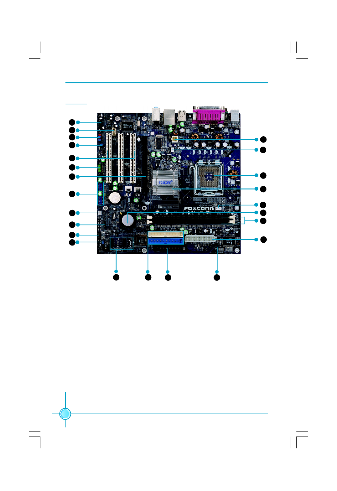
Layout
1
2
3
4
5
6
7
Chapter 1 Product Introduction
24
23
22
8
9
10
11
12
13 14
1. CD_IN Connector
2. AUX_IN Connector (optional)
3. Front Audio Connector
4. BIOS Protection Jumper
5. PCI Expansion Slots
6. COM2 Connector
7. PCI Express x16 Slot
8. USB Connectors
9. System Fan2 Connector
10. IrDA Connector
11. Front Panel Connector
12. Clear CMOS Jumper
15
13. Serial ATA Connectors (optional)
14. ATA 133 /100/66 IDE Connectors
15. FDD Connector
16. Chassis Intruder Connector
17. 24-pin ATX Power Connector
18. 184-pin DIMM Slots
19. South Bridge: SiS965/965L Chipset
20. CPU Fan Connector
21. North Bridge: SiS649 Chipset
22. LGA775 CPU Socket
23. System Fan1 Connector
24. 4-pin ATX_12V Power Connector
16
21
20
19
18
17
Note: This layout is provided for reference, please refer to the physical motherboard.
4
Page 11
Chapter 1 Product Introduction
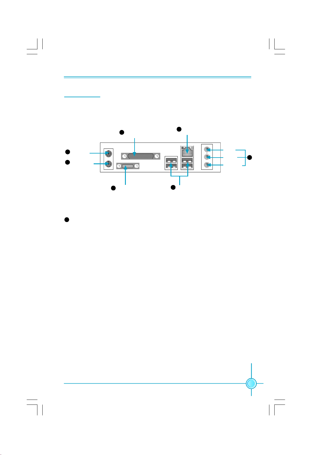
Rear I/O Ports
This motherboard provides the ports as below:
Parallel Port
4
(Printer Port)
6
LAN Port
PS/2 Mouse
1
Connector
PS/2 Keyboard
2
Connector
USB 2.0 Ports
Serial Port
3
3
(COM1)
7
Line in, Line out, Microphone Jacks (for 6-channel)
5
Line-In
Line-Out
Microphone
When using a 2-channel sound source, the Line-Out jack is used to connect to
speaker or headphone; the Line-In jack connects to an external CD player, tape
player or other audio device. The Microphone jack is used to connect to the
microphone.
When using a 6-channel sound source, connect the front speaker to the green
audio output; connect the surround sound speaker to the blue audio output;
connect the center speaker/subwoofer to the red Microphone output.
7
5
Page 12

Chapter 1 Product Introduction
Chapter
This chapter introduces the hardware installation process, in-
cluding the installation of the CPU, memory, power supply,
slots, and pin headers, and the mounting of jumpers. Cau-
tion should be exercised during the installation of these
modules. Please refer to the motherboard layout prior to any
installation and read the contents in this chapter carefully.
This chapter includes the following information:
2
2
v CPU
v Memory
v Power supply
v Other Connectors
v Expansion Slots
v Jumpers
6
Page 13
Chapter 2 Installation Instructions
CPU
This motherboard supports single processors including Celeron D, Pentium4
processors in an LGA775 package with a Front Side Bus (FSB) of 533/800
MHz. It also supports Hyper-Threading technology.
For the detailed CPU support list on this motherboard, please visit the
website: h
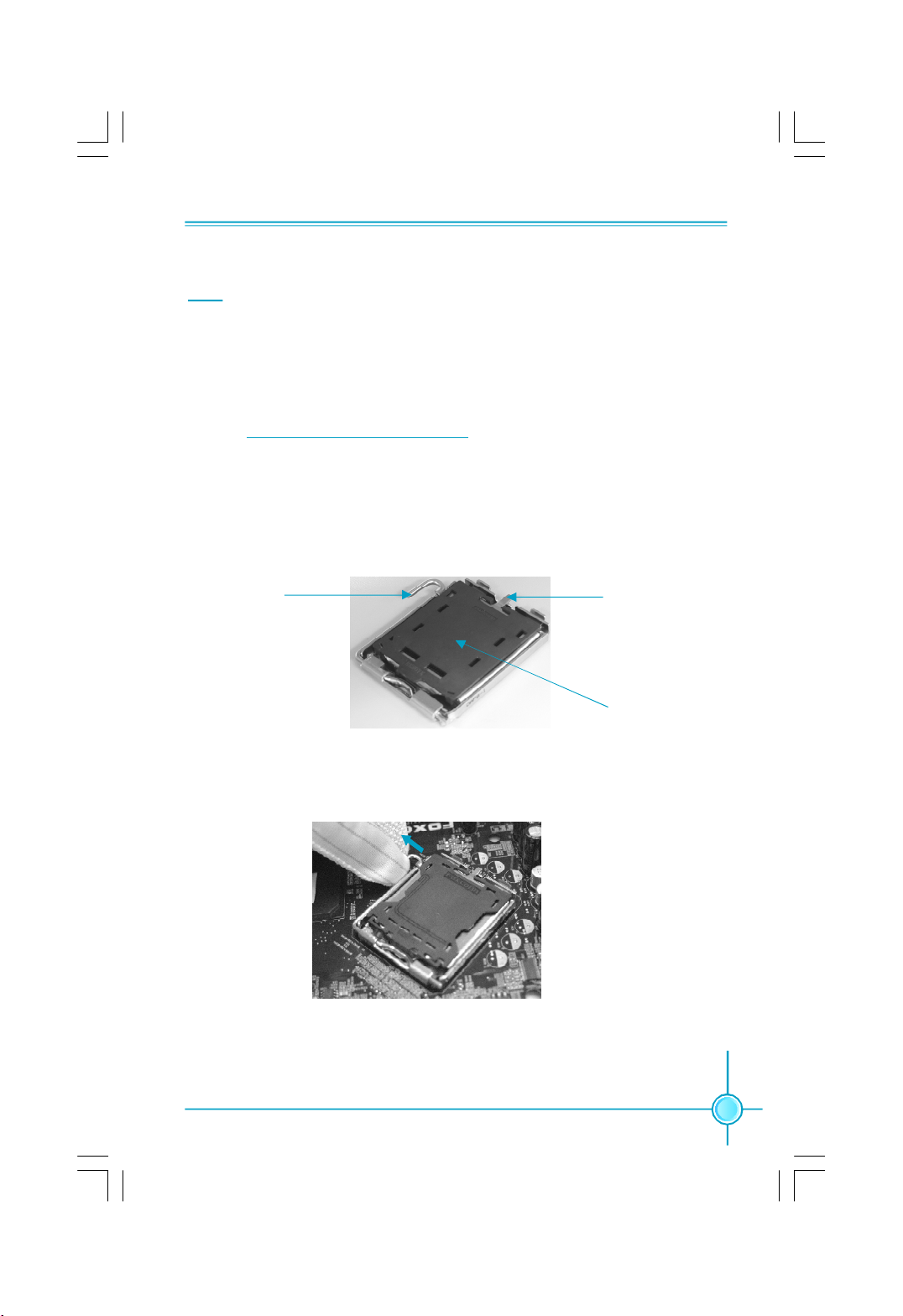
Installation of CPU
Below is the CPU socket illustration. Follow these procedures to install a CPU.
ttp://www.foxconnchannel.com
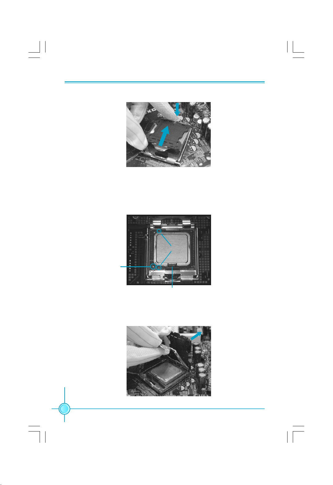
Load lever
1. Use thumb and forefinger to hold the hook of the load lever and pull the lever
down and away from socket to unlock it. Lift the load lever.
2. Push down the rear tab with your forefinger to bring the front end of the load
plate up slightly. Open the load plate with thumb. Be careful not to touch the
contacts.
Load plate
Protective cover
7
Page 14
Chapter 2 Installation Instructions
3. Hold CPU with thumb and forefinger. Ensure fingers align to socket cutouts.
Match the CPU triangle marker to Pin 1 position as shown below. The alignment
key also provides the orientation directed function. Lower the CPU straight down
without tilting or sliding the CPU in the socket.
Alignment Key
Pin 1 position
Socket Cutouts
4. After installing the CPU, remove the protective cover from load plate. The
protective cover is used to protect the contacts of the socket. Do not discard the
protective cover. Always replace the socket cover if the CPU is removed from the
socket.
8
Page 15
Chapter 2 Installation Instructions
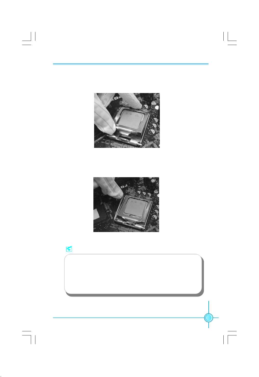
5. Close the load plate, and slightly push down the tongue side.
6. Lower the lever and lock it to the load plate, then the CPU is locked completely.
Note :
Excessive temperatures will severely damage the CPU and
system. Therefore, you should install CPU cooling fan and make
sure that the cooling fan works normally at all times in order to
prevent overheating and damaging to the CPU. Please refer to your
CPU fan user guide to install it properly.
9
Page 16
Chapter 2 Installation Instructions
Memory
This motherboard includes two 184-pin slots with 2.5V for DDR. These slots
support 256 Mb, 512 Mb and 1 Gb DDR technologies for x8 and x16 devices. You
must install at least one memory bank to ensure normal operation.
Installation of DDR Memory
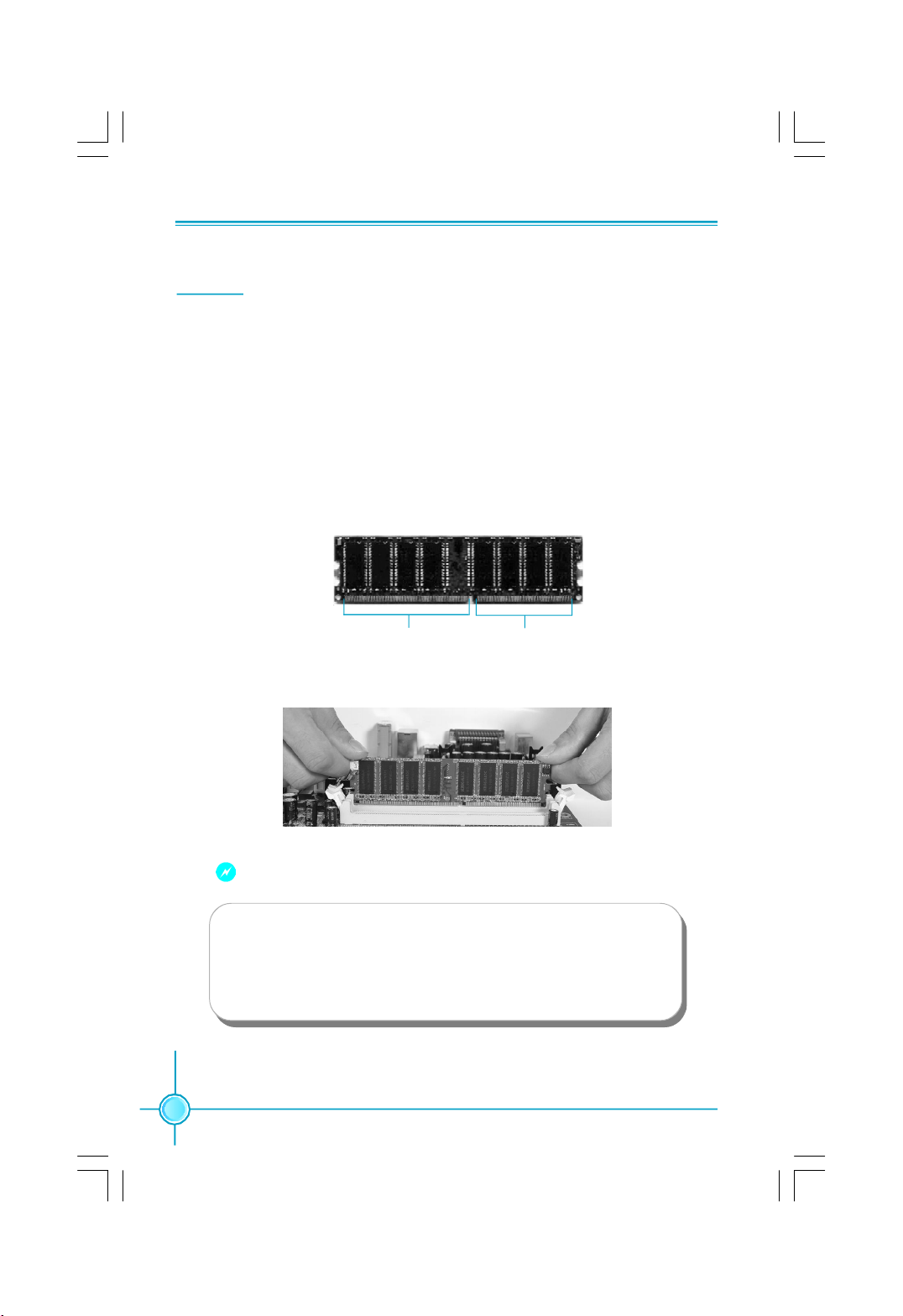
1.There is only one gap near the center of the DIMM slot, and the memory
module can be fixed in one direction only. Unlock a DIMM slot by pressing the
module clips outward.
2.Align the memory module to the DIMM slot, and insert the module vertically
into the DIMM slot.
104 Pins 80 Pins
3.The plastic clips at both sides of the DIMM slot will lock automatically.
10
Warning :
Be sure to unplug the AC power supply before adding or removing
expansion cards or other system peripherals, especially the
memory devices, otherwise your motherboard or the system
memory might be seriously damaged.
Page 17
Chapter 2 Installation Instructions
Power Supply
This motherboard uses an ATX power supply. In order to avoid damaging any
devices, make sure that they have been installed properly prior to connecting
the power supply.
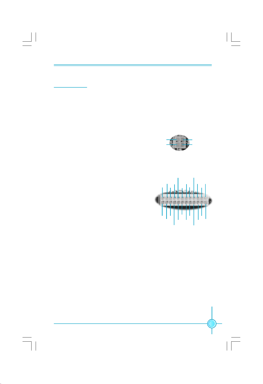
4-pin ATX_12 V Power Connector: PWR2
The ATX power supply connects to PWR2 and
provides power to the CPU.
4-pin ATX_12 V power connector
3
12V
12V
4
1
GND
GND
2
24-pin ATX power connector: PWR1
PWR1 is the ATX power supply connector. Make
sure that the power supply cable and pins are
properly aligned with the connector on the
motherboard. Firmly plug the power supply cable
into the connector and make sure it is secure.
24-pin ATX power connector
RSVD
+5V
+5V
GND
24
12
+12V
+12V
+
PWROK
5V_AUX
+3.3V
GND
GND
PS-ON
GND+5V
+5V
GND
-12V
+3.3V
+3.3V
13
1
+3.3V
GND
GND
GND
+5V
11
Page 18

Chapter 2 Installation Instructions
Other Connectors
This motherboard includes connectors for floppy, IDE devices, Serial ATA
devices, USB devices, IR module, and others.
FDD connector: FLOPPY
This motherboard includes a standard FDD connector, supporting 360 K, 720 K,
1.2 M, 1.44 M, and 2.88 M FDDs.
HDD Connectors: PIDE & SIDE
These connectors support the provided Ultra DMA 133/100/66 IDE hard disk
ribbon cable. Connect the cable’s blue connector to the primary (recommended)
or secondary IDE connector, then connect the gray connector to the Ultra DMA
133/100/66 slave device (hard disk drive) and the black connector to the Ultra
DMA 133/100/66 master device. If you install two hard disks, you must configure
the second drive as a slave device by setting its jumper accordingly. Refer to
the hard disk documentation for the jumper settings.
12
Attention:
Ribbon cables are directional, therefore, make sure to always con-
nect with the cable on the same side as pin 1 of the PIDE/SIDE or
FDD connector on the motherboard.
Page 19

Chapter 2 Installation Instructions
Front Panel Connector: FP1
This motherboard includes one connector for connect-
ing the front panel switch and LED indicators.
HDD_LED
RESET
HDD LED Connector (HDD_LED)
The connector connects to the case’s HDD indicator LED indicating the activity
status of hard disks.
Reset Switch (RESET)
Attach the connector to the Reset switch on the front panel of the case; the
system will restart when the switch is pressed.
Power LED Connector (PWRLED)
Attach the connector to the power LED on the front panel of the case. The Power
LED indicates the system’s status. When the system is in S0 status, the LED is
on. When the system is in S1 status, the LED is blink; When the system is in S3,
S4, S5 status, the LED is off.
1
+
-
NC
FP1
+
PWRLED
-
PWRSW
Empty
Power Switch Connector (PWRSW)
Attach the connector to the power button of the case. Pushing this switch allows
the system to be turned on and off rather than using the power supply button.
Fan Connectors: CPU_FAN, SYS_FAN1, SYS_FAN2
The fan speed of CPU_FAN, SYS_FAN1 and SYS_FAN2 can be detected and
viewed in “PC Health Status” section of the CMOS Setup. Plug the CPU cooling
fan cable into the 4-pin CPU FAN power supply on the motherboard. Connect
the case or system cooling fan connector to SYS_FAN1 or SYS_FAN2.
1
GND
+12V
SENSE
SYS_FAN1/2
1
GND
POWER
SENSE
CONTROL
CPU_FAN
13
Page 20

Chapter 2 Installation Instructions
Audio Connectors: CD_IN, AUX_IN (optional)
CD_IN, AUX_IN is Sony standard CD audio connectors, it can be connected to a
CD-ROM drive through a CD audio cable.
1
CD_IN
CD_R
GND
CD_L
AUX_R
GND
AUX_L
1
AUX_IN
Speaker Connector: SPEAKER
The speaker connector is used to connect speaker of
the chassis.
SPK
Empty
SPKJ
SPEAKER
SPDIF Out Connector: SPDIF_OUT (optional)
The S/PDIF out connector is capable of providing digi-
1
tal audio to external speakers or compressed AC3
data to an external Dolby digital decoder.
Note:The empty pin of SPDIF cable should be aligned
SPDIF_OUT
to empty pin of SPDIF out connector.
S-ATA Connectors: SATA_1, SATA_2, SATA_3, SATA_4 (optional)
The S-ATA headers are used to connect the S-ATA de-
vices to the motherboard. These connectors support
1
the thin Serial ATA cables for primary internal storage
devices. The current Serial ATA interface allows up to
150MB/s data transfer rate.
SATA _1/2/3/4
NC
1
5V
Empty
SPDIF_OUT
GND
GND
TX+
GND
RX+
GND
TX-
RX-
14
Page 21

Chapter 2 Installation Instructions
Front Audio Connector: F_AUDIO
The audio interface provides two kinds of audio
output choices: the Front Audio, the Rear Audio.
Their priority is sequenced from high to low
(Front Audio to Rear Audio). If headphones are
AUD_RET-L
Empty
AUD_RET-R
+5VA
MIC_GND
plugged into the front panel of the chassis
(using the Front Audio), then the Line-out (Rear
F_AUDIO
Audio) on the rear panel will not work. If you do
not want to use the Front Audio, pin 5 and 6,
pin9 and 10 must be SHORT, and then the sig-
nal will be sent to the rear audio port.
USB Connectors: F_USB1, F_USB2
Besides four USB ports on the rear panel, the series of motherboards also
have two 10-pin connectors on board which may connect to front panel USB
cable(optional) to provide additional four USB ports.
AUD_OUT-L
NA
AUD_OUT-R
MIC_PWR
MIC_IN
1
1
VCC
D5-
D5+
GND
Empty
VCC
D4-
D4+
GND
NC
F_USB 1
Additional COM Connector: COM2
This motherboard provides an additional serial
COM connector for your machine.
Connect one side of a switching cable to the
connector, then attach the serial COM device to
the other side of the cable.
VCC
D7-
D7+
GND
Empty
RLSD
SOUT
GND
RTS
1
F_USB 2
1 2
RI
9
COM2
VCC
D6-
D6+
GND
NC
SIN
DTR
DSR
CTS
Empty
10
15
Page 22

Chapter 2 Installation Instructions
IrDA Connector: IR
This connector supports wireless transmitting and re-
ceiving device. Before using this function, configure the
settings of IR Mode from the “ Integrated Peripherals”
section of the CMOS Setup.
Chassis Intruder Connector: INTR
The connector connects to the chassis security switch
on the case. The system can detect the chassis intrusion through the status of this connector. To utilize this
function, set “Case Open Warning” to “Enabled” in the
“PC Health Status” section of the CMOS Setup. Save
and exit to make sure this function takes effect.
Empty
GND
1
IRRX
IRTX
+5V
IR
1 INTRUDERJ 2 GND
INTR
16
Page 23

Chapter 2 Installation Instructions
Expansion Slots
This motherboard includes three 32-bit Master PCI bus slots and one PCI Ex-
press x 16 slot.
PCI Slots
The expansion cards can be installed in the three PCI slots. When you install or
take out such cards, you must make sure that the power plug has been
pulled out. Please read carefully the instructions provided for such cards, and
install and set the necessary hardware and software for such cards, such as
the jumper or BIOS setup.
PCI Express Slot
PCI Express will offer the following design advantages over the PCI and AGP
interface:
-Compatible with existing PCI drivers and software and Operating Systems.
-High Bandwidth per Pin. Low overhead. Low latency.
-PCI Express supports a raw bit-rate of 2.5 Gb/s on the data pins. This
results in a real bandwidth per pair of 250 MB/s.
-A point to point connection, allows each device to have a dedicated connec-
tion without sharing bandwidth.
-Ability to comprehend different data structure.
-Low power consumption and power management features
PCI Express will take two forms, x16 and x1 PCI Express slots. Whereas the x16
slot is reserved for graphic/video cards, the x1 slot is designed to accommo-
date less bandwidth-intensive cards, such as a modem or LAN card.
The difference in bandwidth between the x16 and x1 slots is notable to be sure,
with the x16 slot pushing 4GB/sec (8GB/sec concurrent) of bandwidth, and the
x1 PCI Express slot offering 250MB/sec.
Warning:
If a performance graphics card was installed into 16x PCI Express slot,
2 x 12 pin power supply was strongly recommended.
17
Page 24

Chapter 2 Installation Instructions
Jumpers
The users can change the jumper settings on this motherboard if needed. This
section explains how to use the various functions of this motherboard by chang-
ing the jumper settings. Users should read the following content carefully prior to
modifying any jumper settings.
Description of Jumpers
1. For the jumpers on this motherboard, pin 1 can be identified by the silk-
screen printed “ ” next to it. However, in this manual, pin 1 is simply
labeled as “1”.
2. The following table provides some explanation of the jumper pin settings.
User should refer to this when adjusting jumper settings.
Jumper Diagram Definition Description
1
1
1
1
1
1
1-2 Set pin1 and pin2 closed
2-3 Set pin2 and pin3 closed
Closed Set the pin closed
Open Set the pin opened
Clear CMOS Jumper: CLR_CMOS
The motherboard uses the CMOS RAM to store all
the set parameters. The CMOS can be cleared by
removing the CMOS jumper.
How to clear CMOS?
1. Turn off the AC power supply and connect pins 1
and 2 together using the jumper cap.
2. Return the jumper setting to normal (pins 2 and
3 together with the jumper cap).
3. Turn the AC power supply back on.
Warning:
1. Disconnect the power cable before adjusting the jumper settings.
2. Do not clear the CMOS while the system is turned on.
18
NORMAL
(Default)
CLEAR
1 3 2
1 3 2
CLR_CMOS
Page 25

Chapter 2 Installation Instructions
BIOS Protection Jumper: WP_EN1
The motherboard BIOS is inside the FWH. If the jumper
WP_EN1 is set as CLOSED, the system BIOS is pro-
tected from being attacked by a serious virus, such as
the CIH virus. You will be unable to flash the BIOS
to the motherboard when the system BIOS is protected.
CLOSED
DISABLE
OPEN
ENABLE
WP_EN1
21
3
3
21
19
Page 26

Chapter 3 BIOS Description
Chapter
20
3
3
This chapter tells how to change system settings through the
BIOS Setup menus. Detailed descriptions of the BIOS param-
eters are also provided.
You have to run the Setup Program when the following cases
occur:
1.An error message appears on the screen during the system
POST process.
2.You want to change the default CMOS settings.
This chapter includes the following information:
v Enter BIOS Setup
v Main Menu
v Standard CMOS Features
v BIOS Features
v Advanced BIOS Features
v Advanced Chipset Features
v Integrated Peripherals
v Power Management Setup
v PnP/PCI Configurations
v PC Health Status
v Load Fail-Safe Defaults
v Load Optimized Defaults
v Set Supervisor/User Password
v Save & Exit Setup
v Exit Without Saving
Page 27

Chapter 3 BIOS Description
Enter BIOS Setup
The BIOS is the communication bridge between hardware and software,
correctly setting up the BIOS parameters is critical to maintain optimal system
performance. Power on the computer, when the following message briefly
appears at the bottom of the screen during the POST (Power On Self Test),
press <Del> key to enter the Award BIOS CMOS Setup Utility.
Press TAB to show POST Screen, DEL to enter SETUP.
Note:
We do not suggest that you change the default parameters in the
BIOS Setup, and we shall not be responsible for any damage that
result from any changes that you make.
Main Menu
The main menu allows you to select from the list of setup functions and two exit
choices. Use the arrow keys to select among the items and press <Enter> to
accept or go to the sub-menu.
Main Menu
The items in the main menu are explained as below:
Standard CMOS Features
The basic system configuration can be set up through this menu.
BIOS Features
The special features can be set up through this menu.
21
Page 28

Chapter 3 BIOS Description
Advanced BIOS Features
The advanced system features can be set up through this menu.
Advanced Chipset Features
The values for the chipset can be changed through this menu, and the sys-
tem performance can be optimized.
Integrated Peripherals
All onboard peripherals can be set up through this menu.
Power Management Setup
All the items of Green function features can be set up through this menu.
PnP/PCI Configurations
The system’s PnP/PCI settings and parameters can be modified through
this menu.
PC Health Status
This will display the current status of your PC.
Load Fail-Safe Defaults
The default BIOS settings can be loaded through this menu.
Load Optimized Defaults
The optimal performance settings can be loaded through this menu,
however, the stable default values may be affected.
Set Supervisor Password
The supervisor password can be set up through this menu.
Set User Password
The user password can be set up through this menu.
Save & Exit Setup
Save CMOS value settings to CMOS and exit setup.
Exit Without Saving
Abandon all CMOS value changes and exit setup.
22
Page 29

Chapter 3 BIOS Description
Standard CMOS Features
This sub-menu is used to set up the standard CMOS features, such as the date,
time, HDD model and so on. Use the arrow keys select the item to set up, and
then use the <PgUp> or <PgDn> keys to choose the setting values.
Standard CMOS Features Menu
Date
This option allows you to set the desired date (usually as the current day) with
the <day><month><date><year> format.
Day—weekday from Sun. to Sat., defined by BIOS (read-only).
Month—month from Jan. to Dec..
Date—date from 1st to 31st, can be changed using the keyboard.
Year—year, set up by users.
Time
This option allows you to set up the desired time (usually as the current time)
with <hour><minute><second> format.
IDE Primary/Secondary Master/Slave
These categories identify the HDD types of 2 IDE channels installed in the
computer system. There are three choices provided for the Enhanced IDE BIOS:
None, Auto, and Manual. “None” means no HDD is installed or set; “Auto” means
the system can auto-detect the hard disk when booting up; by choosing “Manual”
and changing Access Mode to “CHS”, the related information should be entered
manually. Enter the information directly from the keyboard and press < Enter>:
Cylinder number of cylinders Head number of heads
Precomp write pre-compensationLanding Zone landing zone
Sector number of sectors
23
Page 30

Chapter 3 BIOS Description
Award (Phoenix) BIOS can support 3 HDD modes: CHS, LBA and Large or Auto mode.
CHS For HDD<528MB
LBA For HDD>528MB & supporting LBA (Logical Block Addressing)
Large For HDD>528MB but not supporting LBA
Auto Recommended mode
Drive A/B
This option allows you to select the kind of FDD to be installed, including “None”,
[360K, 5.25 in], [1.2M, 5.25 in], [720K, 3.5 in], [1.44M, 3.5 in] and [2.88 M, 3.5 in].
Video
The following table is provided for your reference in setting the display mode for
your system.
EGA/VGA Enhanced Graphics Adapter / Video Graphic Array. For
EGA, VGA, SEGA, SVGA, or PGA monitor adapters.
CGA 40 Color Graphic Adapter, powering up in 40 column mode.
CGA 80 Color Graphic Adapter, powering up in 80 column mode.
MONO Monochrome adapter, including high resolution monochrome adapters.
Halt On
This category determines whether or not the computer will stop if an error is
detected during powering up.
All Errors Whenever the BIOS detects a nonfatal error, the system
will stop and you will be prompted.
No Errors The system boot will not stop for any errors that may
be detected.
All, But Keyboard The system boot will not stop for a keyboard error; but
it will stop for all other errors.
All, But Diskette The system boot will not stop for a diskette error; but
it will stop for all other errors.
All, But Disk/Key The system boot will not stop for a keyboard or disk
error, but it will stop for all other errors.
24
Page 31

Chapter 3 BIOS Description
Memory
This is a Display-Only Category, determined by POST (Power On Self Test) of
the BIOS.
Base Memory The BIOS POST will determine the amount of base (or
conventional) memory installed in the system.
Extended Memory The BIOS determines how much extended memory
is present during the POST.
Total Memory Total memory of the system.
25
Page 32

Chapter 3 BIOS Description
BIOS Features
BIOS Features Menu
v[SuperBoot] SuperBoot
SuperBoot allows system-relevant information to be stored in CMOS upon the
first normal start-up of your PC, and the relevant parameters will be restored
to help the system start up more quickly on each subsequent start-up. The
available setting values are: Disabled and Enabled.
v[SuperBIOS-Protect] SuperBIOS-Protect
SuperBIOS-Protect function protects your PC from being affected by viruses,
e.g. CIH. The available setting values are: Disabled and Enabled.
v[SuperRecovery] SuperRecovery Hotkey
SuperRecovery provides the users with an excellent data protection and HDD
recovery function. There are 12 optional hotkey and the default hotkey is
LSHIFT+F12.
v[SuperSpeed]
CPU Clock
This option is used to set the CPU clock.
CPU:DRAM Frequency Ratio
This item is used to set the DRAM frequency ratio.
DRAM Frequency
This item is used to show the DRAM frequency.
Warning:
Be sure your selection is right. CPU overclock will be dangerous!
We will not be responsible for any damages caused.
26
Page 33

Chapter 3 BIOS Description
Advanced BIOS Features
Advanced BIOS Features Menu
v CPU Feature
Press enter to set the items of CPU feature.
vHard Disk Boot Priority
This option is used to select the priority for HDD startup. After pressing
<Enter>, you can select the HDD using the <PageUp>/<PageDn> or Up/
Down arrow keys, and change the HDD priority using <+> or <->; you can
exit this menu by pressing <Esc>.
vVirus Warning
Allows you to choose the VIRUS warning feature for IDE hard disk boot sector
protection. If this function is enabled and someone attempt to write data into
this area, BIOS will show a warning message on screen and an alarm will
beep. The setting values are: Disabled and Enabled.
ote: Such function provides protection to the start-up sector only; it does
N
not protect the entire hard disk.
vCPU L1 & L2 Cache
This option is used to enable or disable the L1 and L2 CPU cache. The
available setting values are: Disabled and Enabled.
vCPU L3 Cache
This option is used to enable or disable the L3 CPU cache. The available
setting values are: Disabled and Enabled.
27
Page 34

Chapter 3 BIOS Description
vHyper-Threading Technology
This option is used to turn on or off the Hyper-Threading function of the CPU.
The available setting values are: Disabled and Enabled.
ote: This function will not be displayed until a CPU that supports
N
Hyper-Threading has been installed.
vCPU L2 Cache ECC Checking
This option is used to enable or disable CPU L2 cache ECC Checking. The
setting values are: Disabled and Enabled.
vQuick Power On Self Test
Enable this option to shorten the power on testing (POST) and have your system start up faster. The setting values are: Disabled and Enabled.
vFirst/Second/Third Boot Device
This option allows you to set the boot device’s sequence.
vBoot Other Device
With this function set to enable, the system will boot from some other devices if the first/second/third boot devices failed. The setting values are: Disabled and Enabled.
vBoot Up NumLock Status
This option defines if the keyboard Num Lock key is active when your system
is started. The setting values are: On and Off.
vTypematic Rate Setting
If this option is enabled, you can use the following two items to see the
typematic rate and the typematic delay settings for your keyboard. The avail-
able setting values are: Disabled and Enabled.
vTypematic Rate (Chars/Sec)
Use this option to define how many characters per second a held-down
key generated.
vTypematic Delay (Msec)
Use this option to define how many milliseconds must elapse before a helddown key beings generating repeat characters.
28
Page 35

Chapter 3 BIOS Description
vSecurity Option
When it is set to “Setup”, a password is required to enter the CMOS Setup
screen; When it is set to “System”, a password is required not only to enter
CMOS Setup, but also to start up your PC.
vMPS Version Control For OS
This option is used to set up the version of MPS Table used in NT4.0 OS.
vOS Select For DRAM > 64MB
This option is only required if you have installed more than 64 MB of memory
and you are running the OS/2 operating system. Otherwise, leave this option
at the default.
vSmall Logo (EPA) Show
This option allows you to enable or disable the EPA logo. The available setting
values are: Disabled and Enabled.
29
Page 36

Chapter 3 BIOS Description
CPU Feature Menu
vThermal Management
This option is used to manage Prescott CPU thermal.
vTM2 Bus Ratio
Represents the frequency bus ratio of the throttled performance state that will
be initiated when the on-die sensor gose from not hot to hot.
vTM2 Bus VID
Represents the voltage of the throttled performance state that will be initiated when the on-die sensor gose from not hot to hot.
vLimit CPUID MaxVal
The option is used to set limit CPUID MaxVal. The available setting values are:
Disabled and Enabled. Set Limit CPUID MaxVal to 3, should be "Disabled" for
WinXP.
vNX BIOS Control
When disabled, forces the NX feature flag to always return 0.
30
Page 37

Chapter 3 BIOS Description
Advanced Chipset Features
Advanced Chipset Features Menu
vDRAM Clock/Drive Control
Press enter to set the items about DRAM Clock/Drive.
vSystem BIOS Cacheable
Select “Enabled” to allow caching of the system BIOS which may improve
performance. If any other program writes to this memory area, a system error
may result. The available setting values are: Enabled and Disabled.
vVideo RAM Cacheable
It is recommended that users set this option as the value “Disabled” so as
to free the memory space and reduce the possibility of conflict occurrence.
vMemory Hole At 15M-16M
This option is used to determine whether the 15M-16M address field of memory
is reserved for the ISA expansion card. The available setting values are: Enabled and Disabled.
31
Page 38

Chapter 3 BIOS Description
DRAM Clock/Timing Control Menu
vDDR CAS Latency
When synchronous DRAM is installed, the number of clock cycles of CAS
latency depends on the DRAM timing.
vDRAM Timing Control
Selects whether DRAM timing is controlled by the SPD (Serial Presence Detect)
EEPROM on the DRAM module. Setting to “Auto” enables DRAM timings to be
determined by BIOS based on the configurations on the SPD. Selecting
“Manual” allows users to configure the DRAM timings manually. The setting
values are: Auto, Manual.
Note: The following options can be activated and configured only when this
option is set as “Manual”.
vRAS to CAS Delay (tRCD)
It is used to set the delay time between RAS (Row Address Strobe) and CAS
(Column Address Strobe) signals. The setting values are: 2T, 3T, 4T, 5T.
vPrecharge Time (tRP)
It is used to set the precharge time of RAS. The setting values are: 2T, 3T, 4T,
5T.
vRAS to Active Time (tRCD)
It is used to set the RAS to active time. The setting values are: 4T-15T.
v Write Recovery Time (tWR)
It is used to set the write recovery time. The setting values are: 1T, 2T, 3T, 4T,
5T, 6T.
vDDR 128-Bit Access
It is used to set whether 128-bit access is allowed or not.
vECC Data Check
It is used to enable or disable ECC data check function.
32
Page 39

Chapter 3 BIOS Description
Integrated Peripherals
Integrated Peripherals Menu
vSIS OnChip IDE Device
Press the <Enter> key to enter the setup sub-menu.
vSIS OnChip IDE Device
Press the <Enter> key to enter the setup sub-menu.
vOnboard SuperIO Device
Press the <Enter> key to enter the setup sub-menu.
v Onboard Lan Device
This option is used to enable or disable onboard LAN device. The setting
values are: Disabled and Enabled.
vIDE HDD Block Mode
This option is used to set whether IDE HDD block mode is allowed. Selecting
“Enabled” will set IDE HDD as block mode. When disabled, IDE HDD does
not support block mode.
v Onboard Lan Boot ROM
The option enables or disables the initialization of the onboard LAN Boot
ROM during bootup. The setting values are: Disabled and Enabled.
33
Page 40

Chapter 3 BIOS Description
SIS Onchip IDE Menu
vInternal PCI/IDE
This option is used to set the ports of onboard IDE. The available setting
values are: Disabled, Primary, Secondary and Both.
vPrimary/Secondary Master/Salve PIO
These four items let you assign which kind of PIO (Programmed Input/Output)
is used by IDE devices. Choose Auto to let the system auto detect which PIO
mode is best or select a PIO mode from 0-4.
vPrimary/Secondary Master/Salve UDMA
UltraDMA technology provides faster access to IDE devices. If you install a
device that supports UltraDMA, change the appropriate item on this list to
Auto. The available setting values are: Disabled and Auto.
vIDE DMA transfer access
This option is used to enable or disable DMA transfer function of the IDE hard
drives.
34
Page 41

Chapter 3 BIOS Description
SIS Onchip PCI Device Menu
vSIS USB Controller
This option is used to enable or disable SIS USB controller.
vSIS 2.0 Supports
This option is used to enable or disable SIS 2.0 supports.
vUSB Keyboard/Mouse Support
Select “Enabled” if you need to use a USB-interfaced keyboard or mouse in
the operating system. The setting options include Enabled and Disabled.
vSIS AC97 AUDIO
This option is used to set whether onboard AC97 Audio is enabled. The available setting values are: Disabled and Auto.
vSiS Serial ATA Controller
This option is used to enable or disable SiS Serial ATA controller.
vSiS Serial ATA Mode
This option is used to select Serial ATA mode.
35
Page 42

Chapter 3 BIOS Description
Onboard SuperIO Device Menu
vOnboard FDC Controller
This option is used to set whether the Onboard FDC Controller is enabled.
The available setting values are: Disabled and Enabled.
vOnboard Serial Port 1/2
This option is used to assign the I/O address and interrupt request (IRQ) for
the onboard serial port 1/2.
Note: Do not try to set the same values for serial ports 1 and 2.
vUART Mode Select
Use this option to select the UART mode. Setting values include Normal,
IrDA, ASKIR. The setting value is determined by the infrared module installed
on the board.
vUR2 Duplex Mode
This option is available when UART 2 mode is set to either ASKIR or IrDA. This
item enables you to determine the infrared function of the onboard infrared chip.
vOnboard Parallel Port
This item allows you to determine onboard parallel port controller I/O address
and interrupt request (IRQ).
vParallel Port Mode
Select an address and corresponding interrupt for the onboard parallel port.
vECP Mode Use DMA
Select a DMA Channel for the parallel port when using the ECP mode. This
field is only configurable if Parallel Port Mode is set to ECP.
36
Page 43

Chapter 3 BIOS Description
Power Management Setup
Power Management Setup Menu
vACPI Function
ACPI stands for “Advanced Configuration and Power Interface”. ACPI is a
standard that defines power and configuration management interfaces be-
tween an operating system and the BIOS. In other words, it is a standard that
describes how computer components work together to manage system
hardware. In order to use this function the ACPI specification must be sup-
ported by the OS (for example, Windows 2000 or WindowsXP). The available
setting values are: Enabled and Disabled.
vACPI Suspend Type
This option is used to set the energy saving mode of the ACPI function.
When you select “S1 (POS)” mode, the power will not shut off and the power
supply status will remain as it is. In S1 mode the computer can be resumed
at any time. When you select “S3 (STR)” mode, the power will be cut off after
a delay period. The status of the computer before it enters STR will be saved in
memory, and the computer can quickly return to previous status when the STR
function wakes. When you select “S1 & S3” mode, the system will automatically
select the delay time.
vPower Management
This option is used to set the power management scheme. Available setting
values are: User Define, Min Saving, and Max Saving.
vSuspend Mode
This option is used to set the idle time before the system enters into sleep
status. The setting values are Disabled and 1 Min-1 Hour.
37
Page 44

Chapter 3 BIOS Description
vVideo Off Option
This option is used to set video off option. The setting values are: Always On,
Suspend -> Off.
vVideo Off Method
This option is used to define the video off method. “Blank Screen” mode
means that after the computer enters into power saving mode, only the monitor
will close, however, the vertical and horizontal scanning movement of the screen
continues. When you select the “V/H SYNC + Blank” mode the vertical and horizontal scanning movement of screen stops when the computer enters power
saving mode. “DPMS Support” mode is a new screen power management
system, and it needs to be supported by the monitor you’re using.
vSwitch Function
This option is used to enable or disable switch function to wake up. The
setting values are Disabled and Break/Wake.
vMODEM Use IRQ
This option is used to set the IRQ in which the modem can use. The setting
values are: NA, 3, 4, 5, 7, 9, 10, 11.
vHot Key Function As
The option is used to define the hot key function. The available setting values
are Disabled, Power off and Suspend.
vHDD Off After
This option is used to define the continuous HDD idle time before the HDD
enters power saving mode. The setting values are Disabled and 1 Min -15 Min.
vPower Button Override
This option is used to set the power down method. This function is only valid
for systems using an ATX power supply.
When “Instant Off” is selected, press the power switch to immediately turn
off power. When “Delay 4 Sec” is selected, press and hold the power button
for four seconds to turn off power.
vPower State Resume Control
This option is used to control power resume state. The available setting values are Always Off, Always On and Keep Pre-State.
vPM Wake Up Events
Press <Enter> to set the items of PM Wake Up Events.
vDelay Prior to Thermal
This option is used to set the delay time before the CPU enters auto thermal
mode.
37
Page 45

Chapter 3 BIOS Description
PM Wake Up Events Menu
vIRQ [3-7,9-15], NMI
This option is used to enable or disable IRQ[3-7,9-15], NMI.
vIRQ 8 Break Suspend
This option is used to enable or disable IRQ8 break suspend.
vPCIPME Power Up Control
This option is used to enable or disable the system to be waken up by PCI
card.
vPS2KB Power Up Control
This option is used to set which action will wake up PS/2 keyboard from S3/
S4/S5 status. The hotkey is Ctrl+Alt+Backspace. The setting values are Any
Key, Hot Key and Password.
vPS2MS Power Up Control
This option used to set which action will wake up PS/2 mouse from S3/S4/S5
status. The setting values are: Disabled, Click, Move & Click.
vPower UP by Alarm
This option is used to set the timing of the start-up function. In order to use
this function, the start-up password function must be cancelled. Also, the PC
power source must not be turned off.
vMonth Alarm
This option is used to set the timing for the start-up month. The setting values
contain 1 - 12 and NA.
39
Page 46

Chapter 3 BIOS Description
vDay of Month Alarm
This option is used to set the timing for the start-up day of the month. The setting
values contain 0 - 31.
vTime (hh:mm:ss) Alarm
This option is used to set the timing for the start-up time. The setting values
contain hh:0 – 23; mm:0 – 59; ss:0 – 59.
vPrimary/Secondary IDE
When these items are enabled, the system will restart the power saving
timeout counters when any activity is detected on any of the drives or devices
on the primary or secondary IDE channels. The setting values are Disabled and Enabled.
vFDD, COM,LPT Port
When this option is enabled, the system will restart the power saving timeout
counters when any activity is detected on the floppy disk drive, serial ports,
or the parallel port.
vPCI PIRQ [A-D]#
When this option is disabled, any PCI device set as the master will not power
on the system.
40
39
Page 47

Chapter 3 BIOS Description
PnP/PCI Configurations
PnP/PCI Configurations Menu
vInit Display First
This item is used to set which display device will be used first when your PC
starts up. The available setting values are: PCI Slot and PCIEx.
vReset Configuration Data
This option is used to set whether the system is permitted to automatically
distribute IRQ DMA and I/O addresses when each time the machine is turned
on. The setting values are Disabled and Enabled.
vResources Controlled By
This option is used to define the system resource control scheme. If all cards
you use support PNP, then select Auto (ESCD) and the BIOS will automatically
distributes interruption resources. If the ISA cards you installed not support-
ing PNP, you will need to select “Manual” and manually adjust interruption
resources in the event of hardware conflicts. However, since this motherboard
has no ISA slot, this option does not apply.
v PCI/VGA Palette Snoop
If you use a non-standard VGA card, use this option to solve graphic accelera-
tion card or MPEG audio card problems (e.g., colors not accurately displayed).
The setting values are Disabled and Enabled.
vMaximum ASPM Supported
Control maximum level of ASPM supported on the given PCI Express links on
the system.
41
Page 48

Chapter 3 BIOS Description
vMaximum Payload Size
This option is used to maximum TLP payload size for PCI Express devices.
The unit is byte.
42
41
Page 49

Chapter 3 BIOS Description
PC Health Status
PC Health Status menu
vShutdownTemperature
This option is used to set the system temperature upper limit. When the
temperature exceeds the setting value, the motherboard will automatically cut
off power to the computer.
vCase Opened Warning
This option is used to enable or disable case open warning function. The
setting values are Disabled and Enabled.
vSmart Fan Controller
This option is used to enable or disable smart fan function. The setting values
are Disabled and Enabled.
43
Page 50

Chapter 3 BIOS Description
Frequency/Voltage Control
Frequency/Voltage Control Menu
vCPU VID
This option is used to set the value of CPU VID.
vCPU Clock Ratio
This option is used to set the ratio of an unlocked CPU. The possible settings
range from a minimum of 0 to a maximum of 50.
Note: This option is invisible for locking frequency CPU.
vAuto Detect PCI Clk
This option is used to set whether the clock of an unused DIMM/PCI slot will
be disabled to reduce electromagnetic interference. The available settings
are Enabled and Disabled.
vSpread Spectrum
When enabled, it can significantly reduce the EMI (Electromagnetic
Interference) generated by the system.
Warning:
Be sure your selection is right. CPU overclock will be dangerous!
We will not be responsible for any damage caused.
44
Page 51

Chapter 3 BIOS Description
Load Fail-Safe Defaults
Press <Enter> to select this option. A dialogue box will pop up that allows you to
load the default BIOS settings. Select <Y> and then press <Enter> to load the
defaults. Select <N> and press <Enter> to exit without loading. The defaults set
by BIOS set the basic system functions in order to ensure system stability. But if
your computer cannot POST properly, you should load the fail-safe defaults to
restore the original settings. Then carry out failure testing. If you only want to
load the defaults for a single option, you can select the desired option and
press the <F6> key.
Load Optimized Defaults
Select this option and press <Enter>, and a dialogue box will pop up to let you
load the optimized BIOS default settings. Select <Y> and then press <Enter> to
load the optimized defaults. Select <N> and press <Enter> to exit without loading.
The defaults set by BIOS are the optimized performance parameters for the
system, to improve the performance of your system components. However, if
the optimized performance parameters are not supported by your hardware
devices, it will likely cause system reliability and stability issues. If you only want
to load the optimized default for a specific option, select the desired option and
press the <F7> key.
Set Supervisor/User Password
The access rights and permissions associated with the Supervisor password are
higher than those of a regular User password. The Supervisor password can be
used to start the system or modify the CMOS settings. By default, the option “Set
User Password” is displayed in gray and can be activated only when users
assign the Supervisor password. The User password can also start the system.
While the User password can be used to view the current CMOS settings, these
settings cannot be modified using the User password.
When you select the Set Supervisor/User Password option, the following message
will appear in the center of the screen, which will help you to set the password:
Enter Password:
Enter your password, not exceeding 8 characters, then press <Enter>. The
password you enter will replace any previous password. When prompted, key in
the new password and press <Enter>.
45
Page 52

Chapter 3 BIOS Description
If you do not want to set a password, just press <Enter> when prompted to enter
a password, and in the screen the following message will appear. If no password
is keyed in, any user can enter the system and view/modify the CMOS settings.
PASSWORD DISABLED!!!
Press any key to continue …
Under the menu “Advanced BIOS Features” Setup, if you select “System” from
the Security Option, you will be prompted to enter a password once the system
is started or whenever you want to enter the CMOS setting program. If the incor-
rect password is entered, you will not be permitted to continue.
Under the menu “Advanced BIOS Features” Setup, if you select “Setup” from the
Security Option, you will be prompted to enter a password only when you enter
the CMOS setting program.
Save & Exit Setup
When you select this option and press <Enter>, the following message will
appear in the center of the screen:
SAVE to CMOS and EXIT (Y/N)? Y
Press <Y> to save your changes in CMOS and exit the program; press <N> or
<ESC> to return to the main menu.
Exit Without Saving
If you select this option and press <Enter>, the following message will appear
in the center of the screen:
Quit Without Saving (Y/N)? N
Press <Y> to exit CMOS without saving your modifications; press <N> or <ESC>
to return to the main menu.
46
Page 53

Chapter
4
4
The utility CD that came with the motherboard contains use-
ful software and several utility drivers that enhance the
motherboard features.
This chapter includes the following information:
v Utility CD content
v Start to Install drivers
Page 54

Chapter 4 Driver CD Introduction
Utility CD content
This motherboard comes with one Utility CD. To begin using the CD, simply insert
the CD into your CD-ROM drive. The CD will automatically display the main menu
screen.
1. Install Driver
Using this choice, you can install all the drivers for your motherboard. You should
install the drivers in order, and you need to restart your computer after the drivers
are all installed.
A.IDE Driver B.SiS RAID Driver
C.DirectX 9.0 D.USB2.0 Driver
E.Audio Driver F.LAN Driver
2. Accessories
Use this option to install additional software programs.
A. SuperUtility
a. SuperStep
SuperStep is a powerful and easy-to-operate tool for overclocking. You
can quickly increase your CPU’s working frequency through its user-
friendly interface. It will enhance your CPU’s performance and meet all
kinds of DIY requirements.
b.SuperLogo
SuperLogo can display user-designed graphics and pictures, such as a
company logo or personal photos, thus making your PC more personal-
ized and friendly.
48
Page 55

Chapter 4 Driver CD Introduction
c.SuperUpdate
SuperUpdate function can help to update the BIOS through Internet
directly.
B. Adobe Reader
C. Norton Internet Security
3. Browse CD
Click here to browse CD content.
4. HomePage
Click here to visit Foxconn motherboard homepage.
Note:
1. Install the latest service pack firstly if your OS is Windows XP
or Windows 2000.
2. Follow the CD screen order to install your motherboard drivers.
Start to Install Drivers
Click <Install Driver> to enter the driver installation menu screen (shown as
below). Click the relevant buttons to install IDE Driver, SiS RAID Driver,
DirectX 9.0, USB2.0 Driver, Audio Driver and LAN Driver from this CD.
Follow the screen
order to install the
motherboard drivers
49
 Loading...