

Page 1

Statement:
This manual is the intellectual property of Foxconn, Inc. Although the
information in this manual may be changed or modified at any time,
Foxconn does not obligate itself to inform the user of these changes.
Trademark:
All trademarks are the property of their respective owners.
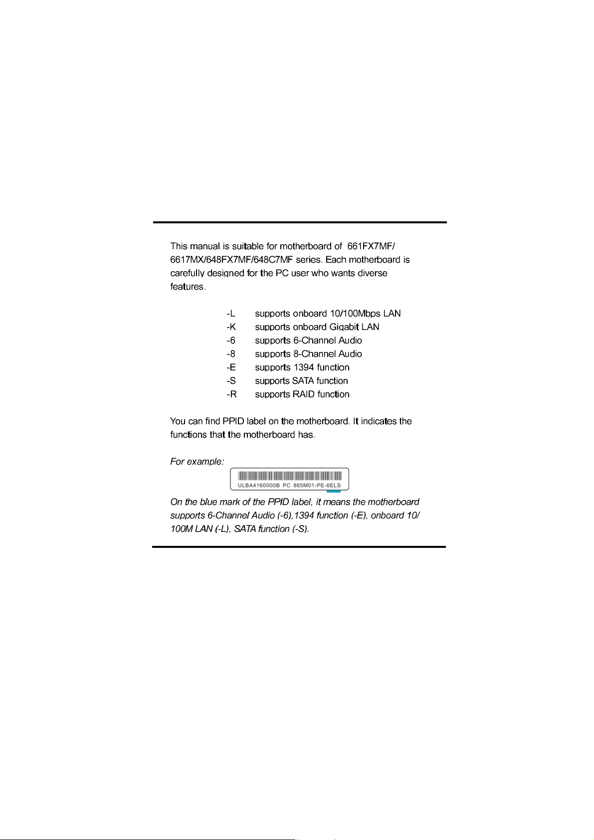
User’s Manual V1.1 in English for 661FX7MF/6617MX/648FX7MF/648C7MF
series motherboard.
P/N: 91-181-A61-FX-1E
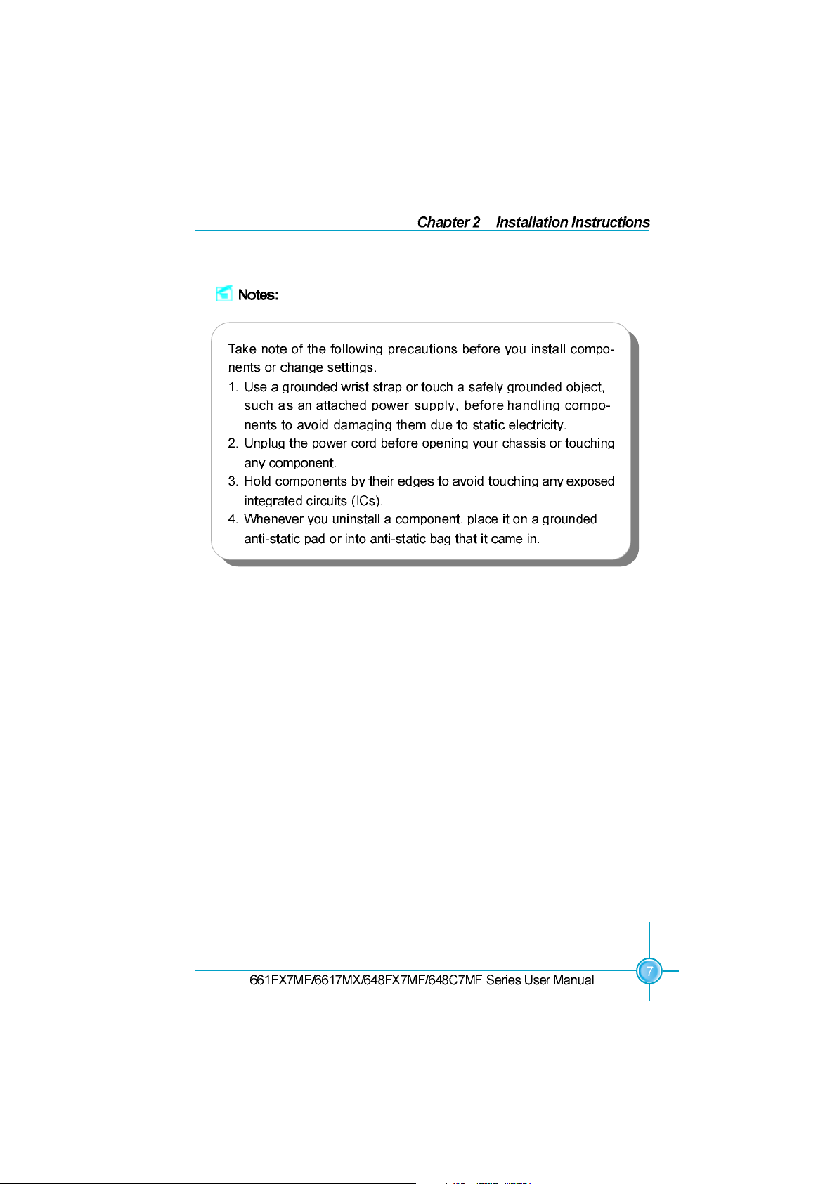
Symbol description:
Note: refers to important information that can help you to use motherboard
better.
Attention: indicates that it may damage hardware or cause data loss,
and tells you how to avoid such problems.
Warning: means that a potential risk of property damage or physical
injury exists.
More information:
If you want more information about our products, please visit Foxconn’s
website:
661M05-648M05-English preface-V1.1.p65 2005-4-9, 8:331
http://www.foxconnchannel.com
Page 2

Declaration of conformity
declares that the product
Motherboard
661FX7MF/6617MX/648FX7MF/648C7MF series
is in conformity with
(reference to the specification under which conformity is declared in
accordance with 89/336 EEC-EMC Directive)
EN 55022/A1: 2000 Limits and methods of measurements of radio disturbance
characteristics of information technology equipment
EN 61000-3-2/A14:2000 Electromagnetic compatibility (EMC)
Part 3: Limits
Section 2: Limits for harmonic current emissions
(equipment input current <= 16A per phase)
EN 61000-3-3/A1:2001 Electromagnetic compatibility (EMC)
Part 3: Limits
Section 2: Limits of voltage fluctuations and flicker in low-voltage
supply systems for equipment with rated current
EN 55024/A1:2001 Information technology equipment-Immunity characteristics limits
and methods of measurement
16A
Signature : Place / Date : T AIPEI/2004
Printed Name : James Liang Position/ Title : Assistant President
661M05-648M05-English preface-V1.1.p65 2005-4-9, 8:332
Page 3

Declaration of conformity
Trade Name:
Model Name: 661FX7MF/6617MX/648FX7MF/648C7MF
Responsible Party:
Telephone: 714-738-8868
Facsimile: 714-738-8838
Equipment Classification: FCC Class B Subassembly
Type of Product: Motherboard
Manufacturer: HON HAI PRECISION INDUSTRY
COMPANY LTD
Address: 66 , CHUNG SHAN RD., TU-CHENG
INDUSTRIAL DISTRICT, TAIPEI HSIEN,
TAIWAN, R.O.C.
Supplementary Information:
This device complies with Part 15 of the FCC Rules. Operation is subject to the
following two conditions : (1) this device may not cause harmful interference, and (2)
this device must accept any interference received, including interference that may
cause undesired operation.
Tested to comply with FCC standards.
Signature : Date : 2004
661M05-648M05-English preface-V1.1.p65 2005-4-9, 8:333
Page 4
Table of Contents
Chapter
Motherboard Layout .................................................................................... 5
Product Introduction
Installation Instructions
CPU.............................................................................................................. 8
Memory ...................................................................................................... 12
Power Supply ............................................................................................ 16
Rear Panel Connectors .............................................................................. 17
Other Connectors ...................................................................................... 19
Expansion Slots ......................................................................................... 23
Jumpers..................................................................................................... 25
BIOS Description
Enter BIOS Setup ....................................................................................... 28
Main Menu ................................................................................................. 28
Standard CMOS Features .......................................................................... 30
BIOS Features ........................................................................................... 33
Advanced BIOS Features .......................................................................... 34
Advanced Chipset Features ...................................................................... 39
Integrated Peripherals ................................................................................ 43
Power Management Setup ......................................................................... 47
PnP/PCI Configurations............................................................................... 51
PC Health Status ........................................................................................ 52
Frequency/Voltage Control......................................................................... 53
Load Fail-Safe Defaults ............................................................................. 54
Load Optimized Defaults ............................................................................ 54
Set Supervisor/User Password ................................................................. 54
Save & Exit Setup ...................................................................................... 55
Exit Without Saving .................................................................................... 55
661M05-648M05-English preface-V1.1.p65 2005-4-9, 8:334
Page 5

Utility CD content........................................................................................
661M05-648M05-English preface-V1.1.p65 2005-4-9, 8:335
Page 6
661M05-648M05-English preface-V1.1.p65 2005-4-9, 8:336
Page 7
661M05-648M05-English preface-V1.1.p65 2005-4-9, 8:337
Page 8
661M05-648M05-FOXCONN-V1.1-HW-en.p65 2005-4-9, 8:561
Page 9
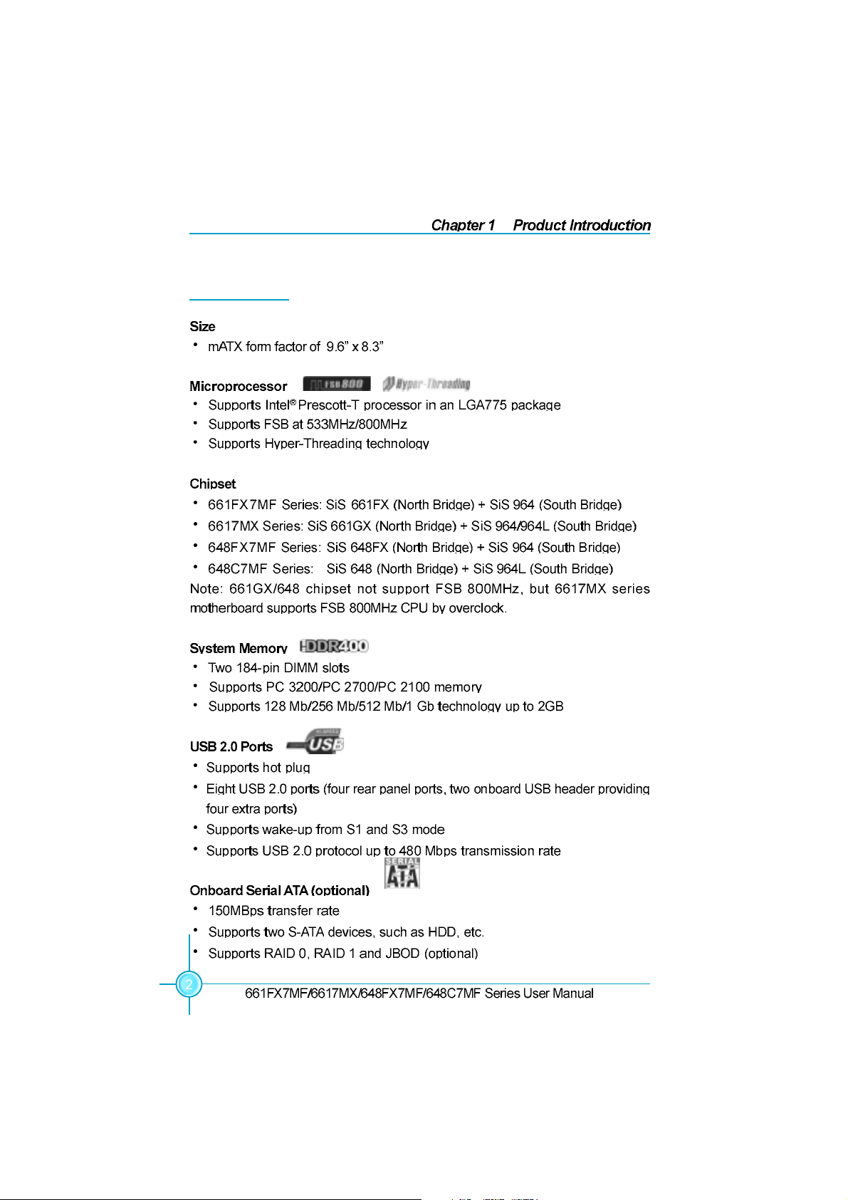
Main Features
661M05-648M05-FOXCONN-V1.1-HW-en.p65 2005-4-9, 8:562
Page 10
661M05-648M05-FOXCONN-V1.1-HW-en.p65 2005-4-9, 8:563
Page 11
661M05-648M05-FOXCONN-V1.1-HW-en.p65 2005-4-9, 8:564
Page 12
661M05-648M05-FOXCONN-V1.1-HW-en.p65 2005-4-9, 8:565
Page 13

661M05-648M05-FOXCONN-V1.1-HW-en.p65 2005-4-9, 8:566
Page 14
661M05-648M05-FOXCONN-V1.1-HW-en.p65 2005-4-9, 8:567
Page 15
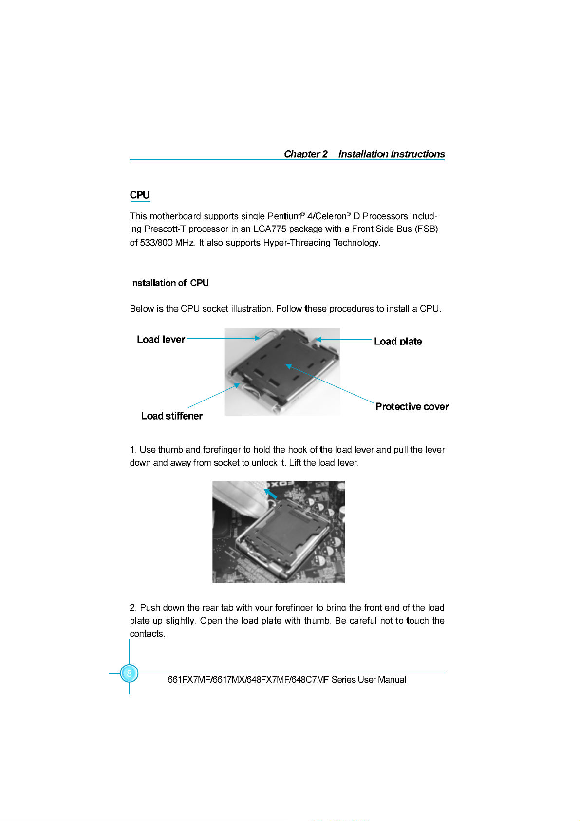
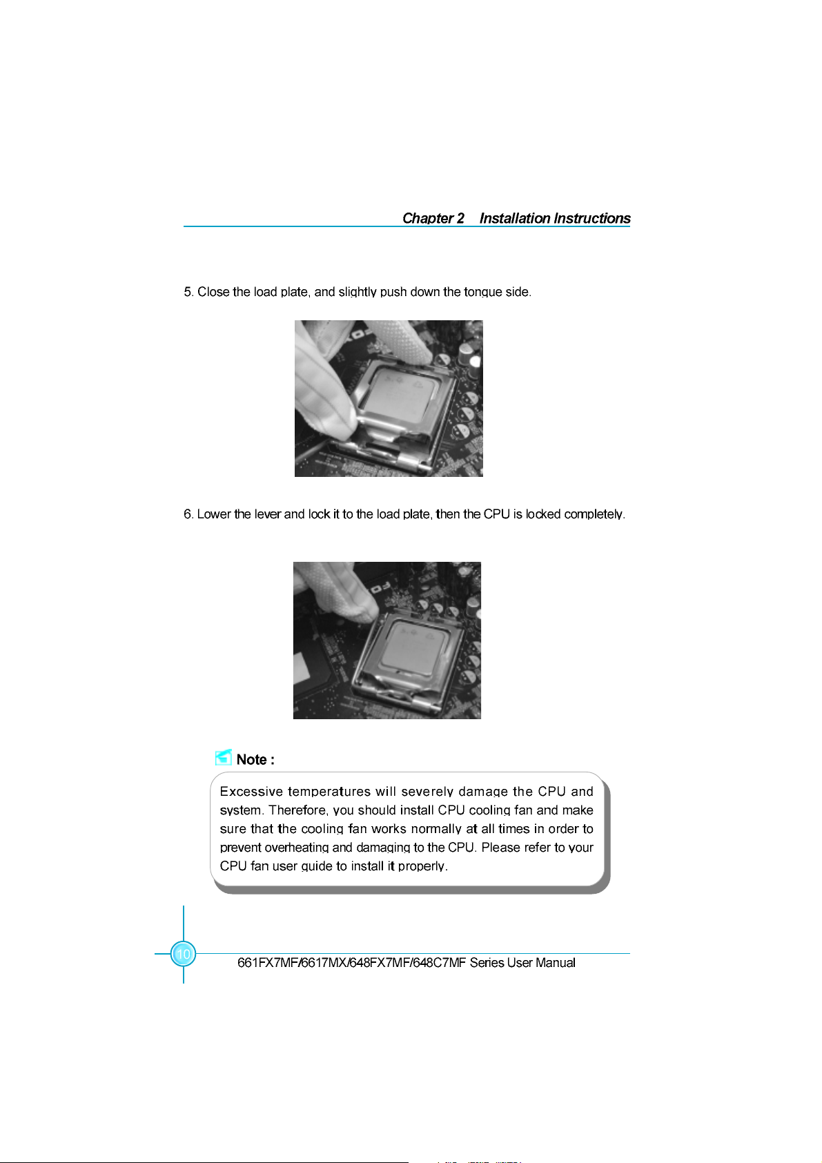
I
661M05-648M05-FOXCONN-V1.1-HW-en.p65 2005-4-9, 8:568
Page 16
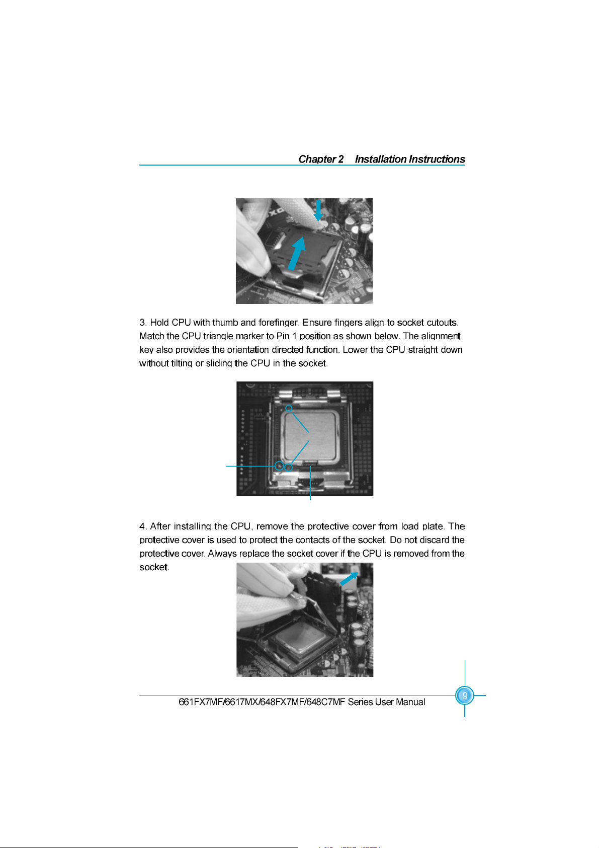
Pin 1 position
Alignment Key
Socket Cutouts
661M05-648M05-FOXCONN-V1.1-HW-en.p65 2005-4-9, 8:569
Page 17
661M05-648M05-FOXCONN-V1.1-HW-en.p65 2005-4-9, 8:5610
Page 18
661M05-648M05-FOXCONN-V1.1-HW-en.p65 2005-4-9, 8:5611
Page 19
I
661M05-648M05-FOXCONN-V1.1-HW-en.p65 2005-4-9, 8:5612
Page 20
661M05-648M05-FOXCONN-V1.1-HW-en.p65 2005-4-9, 8:5613
Page 21

661M05-648M05-FOXCONN-V1.1-HW-en.p65 2005-4-9, 8:5714
Page 22

661M05-648M05-FOXCONN-V1.1-HW-en.p65 2005-4-9, 8:5715
Page 23

3.3V
3.3V
1
5V
5V
GND GND GND 5VSB
PWR-OK
12V
10
11
GND
GND
PS-ON
GND
5V
-5V 5V
GND
3.3V
-12V
20
661M05-648M05-FOXCONN-V1.1-HW-en.p65 2005-4-9, 8:5716
Page 24

661M05-648M05-FOXCONN-V1.1-HW-en.p65 2005-4-9, 8:5717
Page 25

661M05-648M05-FOXCONN-V1.1-HW-en.p65 2005-4-9, 8:5718
Page 26

661M05-648M05-FOXCONN-V1.1-HW-en.p65 2005-4-9, 8:5719
Page 27

+ -
1 + -
FP1
661M05-648M05-FOXCONN-V1.1-HW-en.p65 2005-4-9, 8:5720
Page 28

CPU_FAN
1
FAN1
661M05-648M05-FOXCONN-V1.1-HW-en.p65 2005-4-9, 8:5721
+12V
Page 29

NA
1
INTRUDERJ
GND
661M05-648M05-FOXCONN-V1.1-HW-en.p65 2005-4-9, 8:5722
Page 30

661M05-648M05-FOXCONN-V1.1-HW-en.p65 2005-4-9, 8:5723
Page 31

661M05-648M05-FOXCONN-V1.1-HW-en.p65 2005-4-9, 8:5724
Page 32

Normal Status
(Default)
3
1
2
3
2
1
661M05-648M05-FOXCONN-V1.1-HW-en.p65 2005-4-9, 8:5725
Page 33

661M05-648M05-FOXCONN-V1.1-HW-en.p65 2005-4-9, 8:5726
Page 34

Chapter
661FX7MF/6617MX/648FX7MF/648C7MF Series User Manual
Chapter 3 BIOS Description
This chapter tells how to change system settings through the
BIOS Setup menus. Detailed descriptions of the BIOS parameters
are also provided.
Y ou have to run the Setup Program when the following cases occur:
1. An error message appears on the screen during the system
POST process.
2. You want to change the default CMOS settings.
This chapter includes the following information:
Enter BIOS Setup
Main Menu
Standard CMOS Features
BIOS Features
Advanced BIOS Features
Advanced Chipset Features
Integrated Peripherals
Power Management Setup
PnP/PCI Configurations
PC Health Status
Frequency/Voltage Control
Load Fail-Safe Defaults
Load Optimized Defaults
Set Supervisor/User Password
Save & Exit Setup
Exit Without Saving
27
Page 35

Chapter 3 BIOS Description
Enter BIOS Setup
The BIOS is the communication bridge between hardware and software,
correctly setting up the BIOS parameters is critical to maintain optimal system
performance. Power on the computer, when the following message briefly
appears at the bottom of the screen during the POST (Power On Self Test),
press <Del> key to enter the AWARD BIOS CMOS Setup Utility.
Press TAB to show POST screen, DEL to enter SETUP.
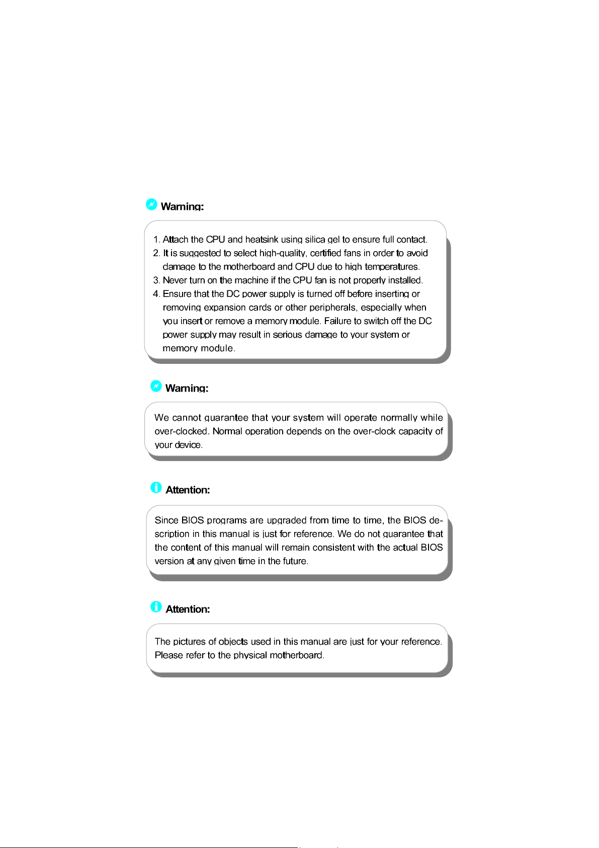
Note:
We do not suggest that you change the default parameters in the
BIOS Setup, and we shall not be responsible for any damage that
result from any changes that you make.
Main Menu
The main menu allows you to select from the list of setup functions and two exit
choices. Use the arrow keys to select among the items and press <Enter> to
accept or go to the sub-menu.
Main Menu
The items in the main menu are explained as below:
Standard CMOS Features
The basic system configuration can be set up through this menu.
BIOS Features
The special features can be set up through this menu.
28
661FX7MF/6617MX/648FX7MF/648C7MF Series User Manual
Page 36

Chapter 3 BIOS Description
Advanced BIOS Features
The advanced system features can be set up through this menu.
Advanced Chipset Features
The values for the chipset can be changed through this menu, and the system performance can be optimized.
Integrated Peripherals
All onboard peripherals can be set up through this menu.
Power Management Setup
All the items of green function features can be set up through this menu.
PnP/PCI Configurations
The system’s PnP/PCI settings and parameters can be modified through
this menu.
PC Health Status
This will display the current status of your PC.
Frequency/Voltage Control
Frequency and voltage settings can be adjusted through this menu.
Load Fail-Safe Defaults
The default BIOS settings can be loaded through this menu.
Load Optimized Defaults
The optimal performance settings can be loaded through this menu,
however, the stable default values may be affected.
Set Supervisor/User Password
The supervisor/user password can be set up through this menu.
Save & Exit Setup
Save CMOS value settings to CMOS and exit setup.
Exit Without Saving
Abandon all CMOS value changes and exit setup.
661FX7MF/6617MX/648FX7MF/648C7MF Series User Manual
29
Page 37

Chapter 3 BIOS Description
Standard CMOS Features
This sub-menu is used to set up the standard CMOS features, such as the date,
time, HDD model and so on. Use the arrow keys select the item to set up, and
then use the <PgUp> or <PgDn> keys to choose the setting values.
Standard CMOS Features Menu
Date
This option allows you to set the desired date (usually as the current date)
with the <day><month><date><year> format.
Day—weekday from Sun. to Sat., defined by BIOS (read-only).
Month—month from Jan. to Dec..
Date—date from 1
Year—year, set up by users.
st
to 31st, can be changed using the keyboard.
Time
This option allows you to set up the desired time (usually as the current time)
with <hour><minute><second> format.
IDE Channel 0/1 Master/Slave & IDE Channel 2/3 Master
These categories identify the HDD types of 2 IDE channels installed in the
computer system. There are three choices provided for the Enhanced IDE BIOS:
None, Auto, and Manual. “None” means no HDD is installed or set; “Auto” means
the system can auto-detect the hard disk when booting up; by choosing “Manual”
and changing Access Mode to “CHS”, the related information should be entered
manually. Enter the information directly from the keyboard and press < Enter>:
Cylinder number of cylinders Head number of heads
Precomp write pre-compensation Landing Zone landing zone
Sector number of sectors
30
661FX7MF/6617MX/648FX7MF/648C7MF Series User Manual
Page 38

Chapter 3 BIOS Description
Award (Phoenix) BIOS can support 3 HDD modes: CHS, LBA and Large or Auto mode.
CH S For HDD<528MB
LBA For HDD>528MB & supporting LBA (Logical Block Addressing)
Large For HDD>528MB but not supporting LBA
Auto Recommended mode
Drive A/B
This option allows you to select the kind of FDD to be installed, including “None”,
[360K, 5.25 in], [1.2M, 5.25 in], [720K, 3.5 in], [1.44M, 3.5 in] and [2.88 M, 3.5 in].
Video
The following table is provided for your reference in setting the display mode for
your system.
EGA/VGA Enhanced Graphics Adapter / Video Graphic Array. For
EGA, VGA, SEGA, SVGA, or PGA monitor adapters.
CGA 40 Color Graphic Adapter, powering up in 40 column mode.
CGA 80 Color Graphic Adapter, powering up in 80 column mode.
MONO Monochrome adapter, including high resolution monochrome adapters.
Halt On
This category determines whether or not the computer will stop if an error is
detected during powering up.
All Errors Whenever the BIOS detects a nonfatal error, the system
will stop and you will be prompted.
No Er ror s The system boot will not stop for any errors that may
be detected.
All, But Keyboard The system boot will not stop for a keyboard error; but
it will stop for all other errors.
All, But Diskette The system boot will not stop for a diskette error; but it
will stop for all other errors.
All, But Disk/Key The system boot will not stop for a keyboard or disk
error, but it will stop for all other errors.
661FX7MF/6617MX/648FX7MF/648C7MF Series User Manual
31
Page 39

Chapter 3 BIOS Description
Memory
This is a Display-Only Category, determined by POST (Power On Self Test) of
the BIOS.
Base Memory The BIOS POST will determine the amount of base
(or conventional) memory installed in the system.
Extended Memory The BIOS determines how much extended memory
is present during the POST.
Total Memory Total memory of the system.
32
661FX7MF/6617MX/648FX7MF/648C7MF Series User Manual
Page 40

Chapter 3 BIOS Description
BIOS Features
BIOS Features Menu
[SuperBoot] SuperBoot ( Default: Disabled )
SuperBoot allows system-relevant information to be stored in CMOS upon the
first normal start-up of your PC, and the relevant parameters will be restored
to help the system start up more quickly on each subsequent start-up. The
available setting values are: Disabled and Enabled.
[SuperBIOS-Protect] SuperBIOS-Protect ( Default: Disabled )
SuperBIOS-Protect function protects your PC from being affected by viruses,
e.g. CIH. The available setting values are: Disabled and Enabled.
[SuperRecovery] SuperRecovery Hotkey ( Default: LSHIFT+F12)
SuperRecovery provides the users with an excellent data protection and HDD
recovery function. There are 12 optional hotkey and the default hotkey is
LSHIFT+F12.
[SuperSpeed] CPU Clock (Depending on the specification of the CPU)
The conventional over-clock method uses the jumpers on the motherboard,
and it is both troublesome and apt to errors. By using SuperSpeed, a CPU
can be overclocked by keying in the desired in the CPU clock range.
CPU: DRAM Frequency Ratio (Default: SPD)
This option is used to set CPU:DRAM Frequency Ratio.
DRAM Frequency
This option is used to show DRAM frequency.
Warning:
Be sure your selection is right. CPU overclock will be dangerous!
We will not be responsible for any damage caused.
661FX7MF/6617MX/648FX7MF/648C7MF Series User Manual
33
Page 41

Chapter 3 BIOS Description
Advanced BIOS Features
Advanced BIOS Features Menu
CPU Feature
Press enter to set the items of CPU feature. Please refer to page 38.
Hard Disk Boot Priority
This option is used to select the priority for HDD startup. After pressing
<Enter>, you can select the HDD using the <PageUp>/<PageDn> or Up/
Down arrow keys, and change the HDD priority using <+> or <->; you can
exit this menu by pressing <Esc>.
Virus Warning (Default: Disabled)
Allows you to choose the VIRUS warning feature for IDE hard disk boot sector
protection. If this function is enabled and someone attempt to write data into
this area, BIOS will show a warning message on screen and an alarm will
beep. The available setting values are: Disabled and Enabled.
Note: Such function provides protection to the start-up sector only; it does
not protect the entire hard disk.
CPU L1 & L2 Cache (Default: Enabled)
This option is used to enable or disable the CPU L1 and L2 cache. The
available setting values are: Disabled and Enabled.
CPU L3 Cache (Default: Disabled) (optional)
This option is used to enable or disable CPU L3 cache. The available setting
values are: Disabled and Enabled.
34
661FX7MF/6617MX/648FX7MF/648C7MF Series User Manual
Page 42

Chapter 3 BIOS Description
Hyper-Threading Technology (Default: Enabled)(optional)
This option is used to turn on or off the Hyper-Threading function of the CPU.
The available setting values are: Disabled and Enabled.
Note: This function will not be displayed until a CPU that supports Hyper-
Threading has been installed.
CPU L2 Cache ECC Checking (Default: Enabled)
This option is used to enable or disable CPU L2 cache ECC Checking. The
available setting values are: Disabled and Enabled.
Quick Power On Self Test (Default: Enabled)
Enable this option to shorten the power on testing (POST) and have your system start up faster. The available setting values are: Disabled and Enabled.
First/Second/Third Boot Device (Default: Floppy/H ard Disk/CDROM)
This option allows you to set the boot device’s sequence. The available
setting values are: Floppy, LS120, Hard Disk, CDROM, ZIP100, USB-FDD,
USB-ZIP, USB-CDROM, LAN, and Disabled.
Boot Other Device (Default: Enabled)
With this function set to enable, the system will to boot from some other
devices if the first/second/third boot devices failed. The available setting values are: Disabled and Enabled.
Swap Floppy Drive (Default: Disabled)
If you have two floppy diskette drives in your system, this option allows you to
swap the assigned drive letters. The available setting values are: Disabled
and Enabled.
Boot Up Floppy Seek (Default: Disabled)
If this option is enabled, BIOS will activate the floppy drive during the system
boot and the drive’s indicator will flash after the activation. The magnetic
head will move back and forth from A to B. The available setting values are:
Disabled and Enabled.
Boot Up NumLock Status (Default: On)
This option defines if the keyboard Num Lock key is active when your system
is started. The available setting values are: On and Off.
Gate A20 Option (Default: Fast)
This option is used to set up the A20 signal control necessary for access to
the 1MB memory. The available setting values are: Normal and Fast.
661FX7MF/6617MX/648FX7MF/648C7MF Series User Manual
35
Page 43

Chapter 3 BIOS Description
Typematic Rate Setting (Default: Disabled)
If this option is enabled, you can use the following two items to see the
typematic rate and the typematic delay settings for your keyboard. The available setting values are: Disabled and Enabled.
Typematic Rate (Chars/Sec) (Default: 6)
Use this option to define how many characters per second a held-down key
generated.
Typematic Delay (Msec) (Default: 250)
Use this option to define how many milliseconds must elapse before a held-
down key begins generating repeat characters.
Security Option (Default: Setup)
When it is set to “Setup”, a password is required to enter the CMOS Setup
screen; When it is set to “System”, a password is required not only to enter
CMOS Setup, but also to start up your PC.
APIC Mode (Default: Enabled)
This option is used to enable or disable APIC mode.
MPS Version Control For OS (Default: 1.4)
This option is used to set up the version of MPS Table used in NT4.0 OS.
OS Select For DRAM > 64MB (Default: Non-OS2)
This option is only required if you have installed more than 64 MB of memory
and you are running the OS/2 operating system. Otherwise, leave this option
at the default.
HDD S.M.A.R.T Capability (Default: Disabled)
This option is used to enable or disable hard disk S.M.A.R.T. support function.
The available setting values are: Disabled and Enabled.
Report No FDD For WIN 95 ( Default: No )
If you are using the Windows 95 and running a system with on floppy drive,
select ”Yes” for this option to ensure compatibility with W indows 95 logo
certification. The available setting values are: No and Yes.
Video BIOS Shadow (Default: Enabled)
This option is used to enable or disable Video BIOS Shadow. If you enable
this option, the video BIOS will be copied to RAM. Video shadow will increase
the video speed. The available setting values are: Disabled and Enabled.
36
661FX7MF/6617MX/648FX7MF/648C7MF Series User Manual
Page 44

Chapter 3 BIOS Description
Full Screen LOGO Show (Default: Enabled)
This option allows you to enable or disable the full screen logo. The available
setting values are: Disabled and Enabled.
Small Logo (EPA) Show (Default: Disabled)
This option allows you to enable or disable the EPA logo. The available setting
values are: Disabled and Enabled.
661FX7MF/6617MX/648FX7MF/648C7MF Series User Manual
37
Page 45

Chapter 3 BIOS Description
CPU Feature Menu
Thermal Management (Default: Thermal Monitor 1)
This option is used to manage Prescott CPU thermal.
Note: This option will not be displayed until a Prescott CPU has been installed.
TM2 Bus Ratio (Default: depend on CPU)(optional)
Represents the frequency bus ratio of the throttled performance state that will
be initiated when the on-die sensor goes from not hot to hot.
TM2 Bus VID (Default: depend on CPU)(optional)
Represents the voltage of the throttled performance state that will be initiated when the on-die sensor goes from not hot to hot.
Limit CPUID MaxVal (Default: Disabled)(optional)
The option is used to set limit CPUID MaxVal. The available setting values are:
Disabled and Enabled.
NX BIOS Control (Default: depend on CPU)(optional)
When disabled, forces the NX feature flag to always return 0. The available
setting values are: Disabled and Enabled.
38
661FX7MF/6617MX/648FX7MF/648C7MF Series User Manual
Page 46

Chapter 3 BIOS Description
Advanced Chipset Features
Advanced Chipset Features Menu
DRAM Clock/Timing Control
Press enter to set the items about DDR RAM. Please refer to page 40.
AGP & P2P Bridge Control
Press enter to set the items about AGP. Please refer to page 41.
OnChip AGP Control (only for 661FX7MF)
Press enter to set the items about onchip AGP. Please refer to page 42.
System BIOS Cacheable (Default: Enabled)
Select “Enabled” to allow caching of the system BIOS which may improve
performance. If any other program writes to this memory area, a system error
may result. The available setting values are: Enabled and Disabled.
Video RAM Cacheable (Default: Enabled)
Select “Enabled” to allow caching of the Video BIOS which may improve
performance. If any other program writes to this memory area, a system error
may result. The available setting values are: Enabled and Disabled.
Memory Hole at 15M-16M (Default: Disabled)
This option is used to determine whether the 15M-16M address field of memory
is reserved for the ISA expansion card. The available setting values are: Enabled and Disabled.
661FX7MF/6617MX/648FX7MF/648C7MF Series User Manual
39
Page 47

Chapter 3 BIOS Description
DRAM Clock/Timing Control Menu
DRAM Timing control (Default: By SPD)
This option determines DRAM timing using SPD or manual configuration.
Only set as manual, the following 4 items can be updated.
DRAM CAS Latency (Default: depend on memory)
This option determines CAS Latency. The available setting values are: 2T, 2.5T,
3T.
RAS Active Time (tRAS) (Default: depend on memory)
This option determines RAS active time. The available setting values are: 4T
- 9T.
RAS Precharge Time (tRP) (Default: depend on memory)
This option is used to define the idle clocks after issuing a precharge command to the SDRAM.
RAS to CAS Delay (tRCD) (Default: depend on memory)
This option is used to define the minimum RAS to CAS delay using 1us
granularity.
40
661FX7MF/6617MX/648FX7MF/648C7MF Series User Manual
Page 48

Chapter 3 BIOS Description
AGP & P2P Bridge Control Menu
AGP Aperture Size (Default: 64 MB)
This option defines the size of the aperture if you use an AGP graphics adapter.
The aperture is a portion of the PCI memory address range dedicated for
graphic memory address space.
Note: This function does not work when Onboard VGA is used.
Graphic Window WR Combin (Default: Disabled)(only for 661FX7MF)
This option is used to disable or enable Graphic Window Write Combin mode.
AGP Fast Write Support (Default: Disabled)(only for 661FX7MF)
Use this option to enable or disable AGP fast write support.
AGP Data Rate (Default: Auto) (only for 661FX7MF)
Use this option to set AGP data rate.
661FX7MF/6617MX/648FX7MF/648C7MF Series User Manual
41
Page 49

Chapter 3 BIOS Description
OnChip AGP Control Menu
VGA Share Memory Size (Default: 32 MB)(only for 661FX7MF)
This option is used to set the onboard VGA share memory size. The available
setting are 16MB, 32MB, 64MB, 128MB.
Graphics Engin Clock (Default: 133 MHz)(only for 661FX7MF)
This option is used to set onchip AGP graphics engin clock. The available
setting are 100 MHz, 133MHZ, 166MHZ, 200MHz.
42
661FX7MF/6617MX/648FX7MF/648C7MF Series User Manual
Page 50

Chapter 3 BIOS Description
Integrated Peripherals
Integrated Peripherals Menu
SIS Onchip IDE Device
Press enter to set onchip IDE device. Please refer to page 44.
SIS Onchip PCI Device
Press enter to set onchip PCI device. Please refer to page 45.
Onboard SuperIO Device
Press enter to set onboard superIO device. Please refer to page 46.
IDE HDD Block Mode (Default: Enabled)
This option is used to set whether the IDE HDD block mode is allowed. The
available setting values are: Disabled and Enabled.
Onboard Lan Boot ROM (Default: Disabled)
This option is used to decide whether to invoke the boot ROM of the onboard
LAN chip.
Init Display First (Default: PCI Slot)
This option is used to set which display device will be used first when your PC
starts up. The available setting values are: AGP and PCI Slot.
USB0/1/2/2.0 Access Interface (Default: EDB Bus)
This option is used to set USB0/1/2/2.0 Access Interface. The available setting values are: PCI Bus and EDB Bus.
MAC Access Interface (Default: EDB Bus)
This option is used to set MAC access interface. The available setting values
are: PCI Bus and EDB Bus.
Audio Access Interface (Default: EDB Bus)
This option is used to set audio Access Interface. The available setting values
are: PCI Bus and EDB Bus.
661FX7MF/6617MX/648FX7MF/648C7MF Series User Manual
43
Page 51

Chapter 3 BIOS Description
SIS OnChip IDE Device Menu
Internal PCI/IDE (Default: Both)
This option is used to set the ports of onboard IDE. The available setting
values are: Disabled, Primary, Secondary and Both.
IDE Primary/ Secondary Master/Slave PIO (Default: Auto)
These four items let you assign which kind of PIO (Programmed Input/Output)
is used by IDE devices. Choose Auto to let the system auto detect which PIO
mode is the best or select a PIO mode from 0-4.
Primary/Secondary Master/Slave UltraDMA (Default: Auto)
UltraDMA technology provides faster access to IDE devices. If you install a
device that supports UltraDMA, change the appropriate item on this list to
Auto. The available setting values are: Disabled and Auto.
IDE DMA transfer access (Default: Enabled)
This option is used to enable or disable IDE DMA transfer access.
IDE Burst Mode (Default: Enabled)
This option is used to enable or disable IDE burst mode.
44
661FX7MF/6617MX/648FX7MF/648C7MF Series User Manual
Page 52

Chapter 3 BIOS Description
SIS OnChip PCI Device Menu
SIS USB Controller (Default: Enabled)
This option is used to enable or disable SIS USB controller.
USB 2.0 Supports (Default: Enabled)
This option is used to enable or disable USB 2.0.
USB Keyboard Support (Default: Enabled)
This option is used to enable or disable USB keyboard under legacy OS.
USB Mouse Support (Default: Enabled)
This option is used to enable or disable USB mouse under legacy OS.
SIS AC97 AUDIO (Default: Enabled)
This option is used to enable or disable SIS AC97 AUDIO.
SIS 10/100M ETHERNET (Default: Enabled)
This option is used to enable or disable SIS 10/100M ethernet.
SiS Serial A T A Controller (Default: Enabled)
This option is used to enable or disable SiS serial ATA controller. The
available setting values are: Disabled and Enabled.
SiS Serial A T A Mode (Default: IDE)
This option is used to set Serial ATA mode. The default is recommended.
The available setting values are: IDE and RAID.
661FX7MF/6617MX/648FX7MF/648C7MF Series User Manual
45
Page 53

Chapter 3 BIOS Description
Onboard SuperIO Device Menu
Onboard FDC Controller (Default: Enabled)
This option is used to set whether the Onboard FDC Controller is enabled.
The available setting values are: Disabled and Enabled.
Onboard Serial Port1/2 (Default: 3F8/IRQ4 / 2F8/IRQ3)
This option is used to assign the I/O address and interrupt request (IRQ) for
the onboard serial port 1/2.
Note: Do not try to set the same values for serial ports 1 and 2.
Onboard Parallel Port (Default: 378/IRQ7)
This option allows you to determine onboard parallel port controller I/O address and interrupt request (IRQ). Setting values include Disabled, 378/IRQ7,
278/IRQ5 and 3BC/IRQ7.
Parallel Port Mode (Default: SPP)
Select an address and corresponding interrupt for the onboard parallel port.
Setting values include SPP, EPP, ECP, ECP+EPP.
ECP Mode Use DMA (Default: 3)
Select a DMA Channel for the parallel port when using the ECP mode. This
field is only configurable if Parallel Port Mode is set to ECP. The available
setting values are: 3 and 1.
46
661FX7MF/6617MX/648FX7MF/648C7MF Series User Manual
Page 54

Chapter 3 BIOS Description
Power Management Setup
Power Management Setup Menu
ACPI function (Default: Enabled)
ACPI stands for “Advanced Configuration and Power Interface”. ACPI is a
standard that defines power and configuration management interfaces between an operating system and the BIOS. In other words, it is a standard that
describes how computer components work together to manage system
hardware. In order to use this function the ACPI specification must be supported by the OS (for example, Windows 2000 or Windows XP). The available
setting values are: Enabled and Disabled.
ACPI Suspend Type (Default: S1(POS))
This option is used to set the energy saving mode of the ACPI function.
When you select “S1 (POS)” mode, the power will not shut off and the
supply status will remain as it is, in S1 mode the computer can beresumed
at any time. When you select “S3 (STR)” mode, the power will be cut off after
a delay period. The status of the computer before it enters STR will be saved
in memory, and the computer can quickly return to previous status when the
STR function wakes. When you select “S1 & S3” mode, the system will
automatically select the delay time.
Power Management (Default: User Define)
This option is used to set the power management scheme. Available settings
are: User Define, Min Saving and Max Saving.
Suspend Mode (Default: Disabled)
This option is used to set the idle time before the system enters into sleep
status. The setting values are: Disabled and 1 Min - 1 hour.
Video Off Option (Default: Susp, Stby - > Off)
This option is used to set video off option. The setting values are: Always On,
Suspend -> Off, Susp,Stby - > Off, All Modes -> Off.
661FX7MF/6617MX/648FX7MF/648C7MF Series User Manual
47
Page 55

Chapter 3 BIOS Description
Video Off Method (Default: DPMS Supported)
This option is used to define the video off method. “Blank Screen” mode
means that after the computer enters power saving mode, only the monitor
will close, however, the vertical and horizontal scanning movement of the screen
continues. When you select the “V/H SYNC + Blank” mode the vertical and horizontal
scanning movement of screen stops when the computer enters power
saving mode. “DPMS Supported” mode is a new screen power management
system, and it needs to be supported by the monitor you’re using.
Switch Function (Default: Break/Wake)
This option is used to enable or disable switch function to wake up. The
setting values are Break/Wake and disabled.
MODEM Use IRQ (Default: AUTO)
This option is used to set the IRQ in which the modem can use. The system
will automatically wake up when the modem receives an incoming call.
Hot Key Function As (Default: Power Off)
The option is used to define the hot key function. The available setting values
are Disabled, Power off, Suspend.
HDD Off After (Default: Disabled)
This option is used to define the continuous HDD idle time before the HDD
enters power saving mode. The setting values are Disabled and 1 Min -15 Min.
Power Button Override (Default: Instant Off)
This option is used to set the power down method. This function is only valid
for systems using an ATX power supply.
When “Instant Off” is selected, press the power switch to immediately turn off power.
When “Delay 4 Sec” is selected, press and hold the power button for four
seconds to turn off power.
Power State Resume Control (Default: Always Off)
This option is used to control power resume state. The available setting val
-ues are Always Off, Always On, Keep Pre-State.
PM Wake Up Events
Press enter to set the items of PM wake up Events. Please refer to page 49.
Delay Prior to Thermal (Default: None)
This option is used to set the delay time before the CPU enters auto thermal
mode. The setting values are: None, 1Min, 2 Min, 4 Min, 8 Min, 16 Min, 32 Min,
64 Min.
48
661FX7MF/6617MX/648FX7MF/648C7MF Series User Manual
Page 56

Chapter 3 BIOS Description
PM Wake Up Events Menu
IRQ [3-7,9-15], NMI (Default: Enabled)
This option is used to enable or disable IRQ[3-7,9-15], NMI.
IRQ 8 Break Suspend (Default: Disabled)
This option is used to enable or disable IRQ8 break suspend.
RING Power Up Control (Default: Enabled)
If this option is enable, it allows the system to resume from a software power
down or power saving mode whenever there is an incoming call to an installed fax/modem. This function needs to be supported by the relevant hardware and software. The setting values are Disabled and Enabled.
MACPME Power Up Control (Default: Enabled)
This option is used to enable or disable the system to be waken up by onboard
LAN.
PCIPME Power Up Control (Default: Enabled)
This option is used to enable or disable the system to be waken up by PCI
card.
PS2KB Wakeup from S3 (Default: Hot Key)
This option is used to set which action will wake up PS/2 keyboard from S3
status. The setting values are Any Key, Hot Key, Password.
PS2MS Wakeup from S3 (Default: Click)
This option is used to set which action will wake up PS/2 mouse from S3
status. The setting values are Disabled, Click, Move & Click.
Power Up by Alarm (Default: Disabled)
This option is used to set the timing of the start-up function. In order to use this
function, the start-up password function must be canceled. Also, the PC power
source must not be turned off. The setting values are Disabled and Enabled.
661FX7MF/6617MX/648FX7MF/648C7MF Series User Manual
49
Page 57

Chapter 3 BIOS Description
Month Alarm
This option is used to set the timing for the start-up month. The setting values
contain 0 - 12 and NA.
Day of Month Alarm
This option is used to set the timing for the start-up day of the month. The setting
values contain 0 - 31.
Time (hh:mm:ss) Alarm
This option is used to set the timing for the start-up time. The setting values
contain hh:0 – 23; mm:0 – 59; ss:0 – 59.
Primary/Secondary IDE (Default: Disabled)
When these items are enabled, the system will restart the power saving timeout
counters when any activity is detected on any of the drives or devices on the
primary or secondary IDE channels. The setting values are Disabled and
Enabled.
FDD, COM,LPT Port (Default: Disabled)
When this option is enabled, the system will restart the power saving timeout
counters when any activity is detected on the floppy disk drive, serial ports, or
the parallel port.
PCI PIRQ [A-D]# (Default: Disabled)
When this option is disabled, any PCI device set as the master will not power
on the system.
50
661FX7MF/6617MX/648FX7MF/648C7MF Series User Manual
Page 58

Chapter 3 BIOS Description
PnP/PCI Configurations
PnP/PCI Configurations Menu
Reset Configuration Data (Default: Disabled)
This option is used to set whether the system is permitted to automatically
distribute IRQ DMA and I/O addresses when each time that the machine is
turned on. The setting values are Disabled and Enabled.
Resources Controlled By (Default: Auto(ESCD))
This option is used to define the system resource control scheme. If all cards
you use support PnP, then select Auto (ESCD) and the BIOS automatically
distributes interruption resources. If you install ISA cards not supporting PnP,
you will need to select “Manual” and manually adjust interruption resources in
the event of hardware conflicts. However, since this motherboard has no ISA
slot, this option does not apply.
IRQ Resources
Press the <Enter> key, then manually set IRQ resources.
PCI/VGA Palette Snoop (Default: Disabled)
If you use a non-standard VGA card, use this option to solve graphic acceleration card or MPEG audio card problems (e.g., colors not accurately displayed).
The setting values are Disabled and Enabled.
661FX7MF/6617MX/648FX7MF/648C7MF Series User Manual
51
Page 59

Chapter 3 BIOS Description
PC Health Status
PC Health Status Menu
CPU Fan Control (Default: Disabled)
This option is used to disable or enable CPU fan control function. The setting
values are Enabled, Disabled.
Shutdown Temperature (Default: Disabled)
This option is used to set the system temperature upper limit. When the
temperature exceeds the setting value, the motherboard will automatically cut
off power to the computer. The setting values are and 60
0
F, 700C/1580F, Disabled.
149
0
C/1400F, 650C/
CPU Vcore/+3.3v/+5v/+12v
The current voltages will be automatically detected by the system.
CPU Tem p
The current CPU temperature will be automatically detected by the system.
The system temperature will be automatically detected by the system.
CPU FAN Speed
The CPU fan speed will be automatically detected by the system.
System FAN Speed
The system fan speed will be automatically detected by the system.
Case Opened Warning (Default: Disabled)
This option is used to enable or disable case opened warning function. The
setting values are Disabled and Enabled.
52
661FX7MF/6617MX/648FX7MF/648C7MF Series User Manual
Page 60

Chapter 3 BIOS Description
Frequency/Voltage Control
Frequency/Voltage Control Menu
CPU Clock Ratio (Default: based on CPU specifications)
This option is used to set the ratio of an unlocked CPU. Using different CPU,
the setting values are different.
Note: this option is invisible for locking frequency CPU.
Auto Detect DIMM/PCI Clk (Default: Enabled)
This option is used to set whether the clock of an unused PCI/DIMM slot will
be disabled to reduce electromagnetic interference. The setting values are:
Disabled and Enabled.
Spread Spectrum (Default: Disabled)
If you enable spread spectrum, it can significantly reduce the EMI (ElectroMagnetic Interference) generated by the system.
Warning:
Be sure your selection is right. CPU overclock will be dangerous!
We will not be responsible for any damages caused.
661FX7MF/6617MX/648FX7MF/648C7MF Series User Manual
53
Page 61

Chapter 3 BIOS Description
Load Fail-Safe Defaults
Press <Enter> to select this option. A dialogue box will pop up that allows you to
load the default BIOS settings. Select <Y> and then press <Enter> to load the
defaults. Select <N> and press <Enter> to exit without loading. The defaults set
by BIOS set the basic system functions in order to ensure system stability. But if
your computer cannot POST properly, you should load the fail-safe defaults to
restore the original settings. Then carry out failure testing. If you only want to
load the defaults for a single option, you can select the desired option the <F6>
key.
Load Optimized Defaults
Select this option and press <Enter>, and a dialogue box will pop up to let you
load the optimized BIOS default settings. Select <Y> and then press <Enter> to
load the optimized defaults. Select <N> and press <Enter> to exit without loading.
The defaults set by BIOS are the optimized performance parameters for the
system, to improve the performance of your system components. However, if
the optimized performance parameters are not supported by your hardware
devices, it will likely cause system reliability and stability issues. If you only want
to load the optimized default for a single option, select the desired option and
press the <F7> key.
Set Supervisor/User Password
The access rights and permissions associated with the Supervisor password are
higher than those of a regular User password. The Supervisor password can be
used to start the system or modify the CMOS settings. The User password can
also start the system. While the User password can be used to view the current
CMOS settings, these settings cannot be modified using the User password.
When you select the Set Supervisor/User Password option, the following message
will appear in the center of the screen, which will help you to set the password:
Enter Password:
Enter your password, not exceeding 8 characters, then press <Enter>. The
password you enter will replace any previous password. When prompted, key in
the new password and press <Enter>.
54
661FX7MF/6617MX/648FX7MF/648C7MF Series User Manual
Page 62

Chapter 3 BIOS Description
If you do not want to set a password, just press <Enter> when prompted to enter
a password, and in the screen the following message will appear. If no password
is keyed in, any user can enter the system and view/modify the CMOS settings.
Password Disabled!!!
Press any key to continue …
Under the menu “Advanced BIOS Features Setup”, if you select “System” from
the Security Option, you will be prompted to enter a password once the system
is started or whenever you want to enter the CMOS setting program. If the incorrect password is entered, you will not be permitted to continue.
Under the menu “Advanced BIOS Features Setup”, if you select “Setup” from the
Security Option, you will be prompted to enter a password only when you enter
the CMOS setting program.
Save & Exit Setup
When you select this option and press <Enter>, the following message will
appear in the center of the screen:
S AVE to CMOS and EXIT (Y/N)?Y
Press <Y> to save your changes in CMOS and exit the program; press <N> or
<ESC> to return to the main menu.
Exit Without Saving
If you select this option and press <Enter>, the following message will appear
in the center of the screen:
Quit Without Saving (Y/N)?N
Press <Y> to exit CMOS without saving your modifications; press <N> or <ESC>
to return to the main menu.
661FX7MF/6617MX/648FX7MF/648C7MF Series User Manual
55
Page 63

Page 64

Page 65

 Loading...