

Page 1

This manual is the intellectual property of Foxconn Inc. Although the
information in this manual may be changed or modified at any time,
Foxconn does not obligate itself to inform the user of these changes.
Statement:
All trademarks are the property of their respective owners.
User’s Manual V1.0 for 6100M2MA series motherboard.
Symbol description:
Version:
Trademark:
Note: refers to important information that can help you to use motherboard
better.
Attention: indicates that it may damage hardware or cause data loss,
and tells you how to avoid such problems.
Warning: means that a potential risk of property damage or physical
injury exists.
More information:
If you want more information about our products, please visit the following
website: http://www.foxconnchannel.com
Page 2

Declaration of conformity
HON HAI PRECISION INDUSTRY COMPANY LTD
66 , CHUNG SHAN RD., TU-CHENG INDUSTRIAL DISTRICT,
TAIPEI HSIEN, TAIWAN, R.O.C.
declares that the product
Motherboard
6100M2MA
is in conformity with
(reference to the specification under which conformity is declared in
accordance with 89/336 EEC-EMC Directive)
þ EN 55022/A1: 2000 Limits and methods of measurements of radio disturbance
characteristics of information technology equipment
þ EN 61000-3-2/A14:2000 Electromagnetic compatibility (EMC)
Part 3: Limits
Section 2: Limits for harmonic current emissions
(equipment input current <= 16A per phase)
þ EN 61000-3-3/A1:2001 Electromagnetic compatibility (EMC)
Part 3: Limits
Section 2: Limits of voltage fluctuations and flicker in low-voltage
supply systems for equipment with rated current <= 16A
þ EN 55024/A1:2001 Information technology equipment-Immunity characteristics limits
and methods of measurement
Signature : Place / Date : TAIPEI/2006
Printed Name : James Liang Position/ Title : Assistant President
Page 3

Declaration of conformity
Trade Name: WinFast
Model Name: 6100M2MA
Responsible Party: PCE Industry Inc.
Address: 458 E. Lambert Rd.
Fullerton, CA 92835
Telephone: 714-738-8868
Facsimile: 714-738-8838
Equipment Classification: FCC Class B Subassembly
Type of Product: Motherboard
Manufacturer: HON HAI PRECISION INDUSTRY
COMPANY LTD
Address: 66 , CHUNG SHAN RD., TU-CHENG
INDUSTRIAL DISTRICT, TAIPEI HSIEN,
TAIWAN, R.O.C.
Supplementary Information:
This device complies with Part 15 of the FCC Rules. Operation is subject to the
following two conditions : (1) this device may not cause harmful interference, and (2)
this device must accept any interference received, including interference that may
cause undesired operation.
Tested to comply with FCC standards.
Signature : Date : 2006
Page 4

Main Features............................................................................................2
Motherboard Layout...................................................................................5
Rear Panel Connectors...............................................................................6
Installation Instructions
CPU............................................................................................................9
Memory....................................................................................................13
Power Supply..........................................................................................15
Other Connectors.....................................................................................16
Expansion Slots........................................................................................21
Jumpers...................................................................................................23
BIOS Description
Enter BIOS Setup......................................................................................26
Main menu................................................................................................26
Standard CMOS Features.........................................................................28
Advanced BIOS Features.........................................................................30
Advanced Chipset Features.....................................................................33
Integrated Peripherals...............................................................................35
Power Management Setup........................................................................40
PnP/PCI Configurations.............................................................................42
PC Health Status.......................................................................................43
Frequency/Voltage Control.......................................................................44
Load Fail-Safe Defaults............................................................................45
Load Optimized Defaults...........................................................................45
Set Supervisor/User Password................................................................45
Save & Exit Setup.....................................................................................46
Exit Without Saving...................................................................................46
Table of Contents
Chapter 1
Chapter
Chapter
3
Product Introduction
2
Page 5

6
Driver CD Introduction
Utility CD content......................................................................................48
Start to install drivers................................................................................49
Directions for Bundled Software
Tiger ONE.................................................................................................51
Fox LiveUpdate........................................................................................57
Table of Contents
4
Chapter
5
Chapter
Page 6

1.Attach the CPU and heatsink using silica gel to ensure full contact.
2.It is suggested to select high-quality, certified fans in order to avoid
damage to the motherboard and CPU due to high temperature.
3.Never turn on the machine if the CPU fan is not properly installed.
4.Ensure that the DC power supply is turned off before inserting or re-
moving expansion cards or other peripherals, especially when you
insert or remove a memory module. Failure to switch off the DC power
supply may result in serious damage to your system or memory
module.
We cannot guarantee that your system will operate normally while
over-clocked. Normal operation depends on the over-clock capacity of
your device.
Attention:
Since BIOS programs are upgraded from time to time, the BIOS de-
scription in this manual is just for reference. We do not guarantee that
the content of this manual will remain consistent with the actual BIOS
version at any given time in the future.
Attention:
The pictures of objects used in this manual are just for your reference.
Please refer to the physical motherboard.
Attention:
Attention:
Page 7

This manual is suitable for motherboard of 6100M2MAseries.
Each motherboard is carefully designed for the PC user who
wants diverse features.
-L with onboard 10/100M LAN(Default is elliptical)
-Kwith onboard Gigabit LAN
-6with 6-channel audio(Default is elliptical)
-8with 8-channel audio
-Ewith 1394 Connector
-Swith SATA Connector
-Rwith RAID function
-2with DDR2 function
You can find PPID label on the motherboard. It indicates the
functions that the motherboard has.
For example:
On the black mark of the PPID label, it means the motherboard
supports 6-Channel Audio (-6), 1394 port (-E), onboard 100M
LAN (-L), SATA function (-S).
Page 8

Chapter
Thank you for buying WinFast 6100M2MA series motherboard.
This series of motherboard is one of our new products, and
offers superior performance, reliability and quality, at a rea-
sonable price. This motherboard adopts the advanced NVIDIA
®
GeForceTM 6100+ nForceTM 430/410 chipset, providing us-
ers a computer platform with a high integration-compatibil-
ity-performance price ratio.
This chapter includes the following information:
v Main Features
v Motherboard Layout
v Rear Panel Connectors
1
1
Page 9

Chapter 1 Product Introduction
2
Main Features
Size:
l mATX form factor of 9.6” x 9.6”
Microprocessor:
l Supports AMD socket AM2 for SempronTM, Athlon
TM
64, Athlon
TM
64 FX,Athlon
TM
64 x2 Dual-Core processors
l Supports HyperTransportTM Technology
Chipset:
l NVIDIA
®
: GeForce
TM
6100+ nForceTM 430/410
System Memory
l Four 240-pin DDR2 Dual channel DIMM slots
l Supports DDR2 800/667/533 memory
l Supports 128/256/512/1024 Mb technology up to 4GB
USB 2.0 Port
l Supports hot-plug
l Eight USB 2.0 ports (four rear panel ports, two onboard USB headers
providing four extra ports)
l Supports USB 2.0 protocol up to 480Mbps transmission rate
Onboard Serial ATA II
l Compliant with the Serial ATA II specification
l 300MBps transfer rate
l nForce 410 support two Serial ATA II devices
l nFurce 430 support four Serial ATA II devices
NVIDIA® RAID Technology
l Supports RAID 0, RAID 1(supported on nFoure 410)
l Supports RAID 0, RAID 1, RAID 0+1, and RAID 5(supported on nFoure 430)
Page 10

3
Chapter 1 Product Introduction
Onboard 1394(optional)
l Supports hot-plug
l Two 1394 ports with rate of transmission at 400Mbps
l Self-configured addressing
Onboard LAN (-L/-K)
l Supports10/100/1000(-K) Mbps Ethernet
l LAN interface built-in on board
Onboard Audio (-6) (optional)
l AC’ 97 2.3 Specification Compliant
l Supports S/PDIF output
l Onboard Line-in jack, Line-out jack, Microphone jack
l Supports 6-channel audio (setting via software)
Onboard Audio (-8) (optional)
l Supports Intel High Definition Audio
l Supports S/PDIF output
l Supports high quality differential CD input
l Supports 8-channel audio
Onboard Graphics
l Supports integrated VGA display functions
BIOS
l Licensed advanced AWARD (Phoenix) BIOS, supports flash ROM, Plug-and-
Play
l Supports IDE HDD, Floppy, CD-ROM, SCSI HDD or USB device boot up
Green Function
l Supports ACPI (Advanced Configuration and Power Interface)
l Supports S0 (normal), S1 (power on suspend), S3 (suspend to RAM), S4
(suspend to disk-depends on OS), and S5 (soft-off) ACPI state
Expansion Slots
l Two PCI slots
l One PCI Express x16 Graphics slot
l One PCI Express x1 Graphics slot
Page 11

Chapter 1 Product Introduction
4
PCI Express x16 graphics support
l Supports 4GB/sec(8 GB/sec concurrent) bandwidth
l Low power consumption and power management features
PCI Express x1 Support
l Supports 250 MB/sec (500 MB/sec concurrent) bandwidth
l Low power consumption and power management features
Advanced Features
l PCI 2.3 Specification Compliant
l Supports PC Health function (capable of monitoring system voltage, CPU/
system temperature, and fan speed)
Page 12
5
Chapter 1 Product Introduction
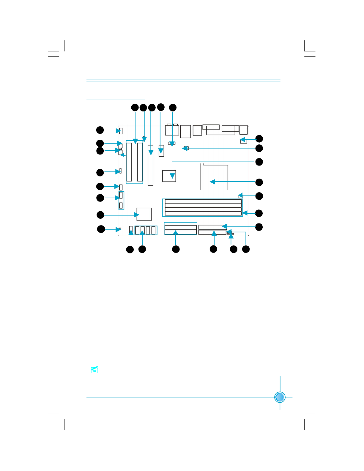
1. Front Audio Connector
2. CD_IN Connector
3. AUX_IN Connector (optional)
4. Speaker Connector(optional)
5. Front 1394 Connector (optional)
6. Front USB Connectors
7. NVIDIA® nForceTM 410/430
8.Chassis Intruder Connector
9. Front Panel Connector
10.SATA II Connectors(optional)
11.IDE Connectors
12. Floppy Disk Connector
13. IrDA Connector
14.Clear CMOS Jumper
15.ATX Power Connector
16. DDR2 DIMM Slots
17. CPU Fan Connector
18. CPU Socket
19. NVIDIA® GeForceTM 6100
20.System FAN Connector
21. 12V ATX Power Connector
22. COM2 Connector
23. PCI Express x1 slot
24. PCI Express x16 slot
25. S/PDIF Out Connector
26. PCI slots
Motherboard Layout
Note:The above motherboard layout is provided for reference
only; please refer to the physical motherboard.
1
2
13
1211
10
9
14
15
16
17
20
21
23
2425 22
3
4
5
6
18
19
26
8
7
Page 13
Chapter 1 Product Introduction
6
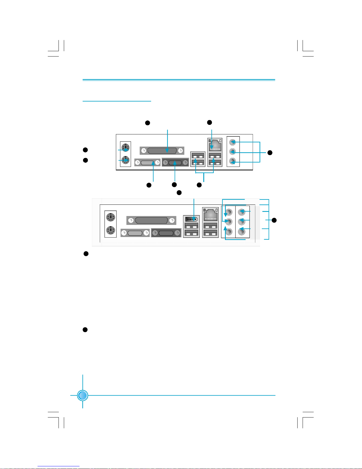
Rear Panel Connectors
This motherboard provides the following ports as below:
10
Line in, Line out, Microphone, Rear, LEF/CEN, Side Jacks (for -8 models)
When using an 8-channel sound source, connect the front speaker to the green
audio output; connect the rear sound speaker to the black audio output; con-
nect the center speaker/subwoofer to the orange audio output; connect the Side
sound speaker to the grey audio output.
COM1
USB 2.0 Port
PS/2 Mouse Port
PS/2 Keyboard Port
Parallel Port
(Printer Port)
LAN Port
4
VGA Port
3
1
2
5
6
7
Line-in
Line-out
10
Microphone
Rear
LFE/CEN
Side
9
1394 Port
(optional)
8
Line-in jack, Line-out jack, Microphone jack(for -6 models)
When using a two-channel sound source, the Line-out jack is used to connect
to speaker or headphone; the Line-in port connects to an external CD player,
tape player or other audio device. The Microphone jack is used to connect to the
microphone.
When using a 6-channel sound source, connect the front speaker to the green
audio output; connect the surround sound speaker to the blue audio input;
connect the center speaker/subwoofer to the red Microphone input.
8
Page 14

7
Chapter 1 Product Introduction
This chapter introduces the hardware installation process,
including the installation of the CPU and memory. It also
addresses the connection of your power supply, connection
of hard drive and floppy drive data cables, and setting up
various other feature of the motherboard. Caution should be
exercised during the installation process. Please refer to
the motherboard layout prior to any installation and read the
contents in this chapter carefully.
This chapter includes the following information:
v CPU
v Memory
v Power Supply
v Other Connectors
v Expansion Slots
v Jumpers
Chapter
2
2
Page 15

8
Chapter 2 Installation Instructions
Notes:
Take note of the following precautions before you install components
or change settings.
1. Use a grounded wrist strap or touch a safely grounded object, such
as an attached power supply, before handling components to avoid
damaging them due to static electricity.
2. Unplug the power cord before opening your chassis or touching any
components.
3. Hold components by their edges to avoid touching any exposed
integrated circuits (ICs).
4. Whenever you uninstall a component, place it on a grounded anti-
static pad or into the anti-static bag that it came in.
Page 16
9
Chapter 2 Installation Instructions
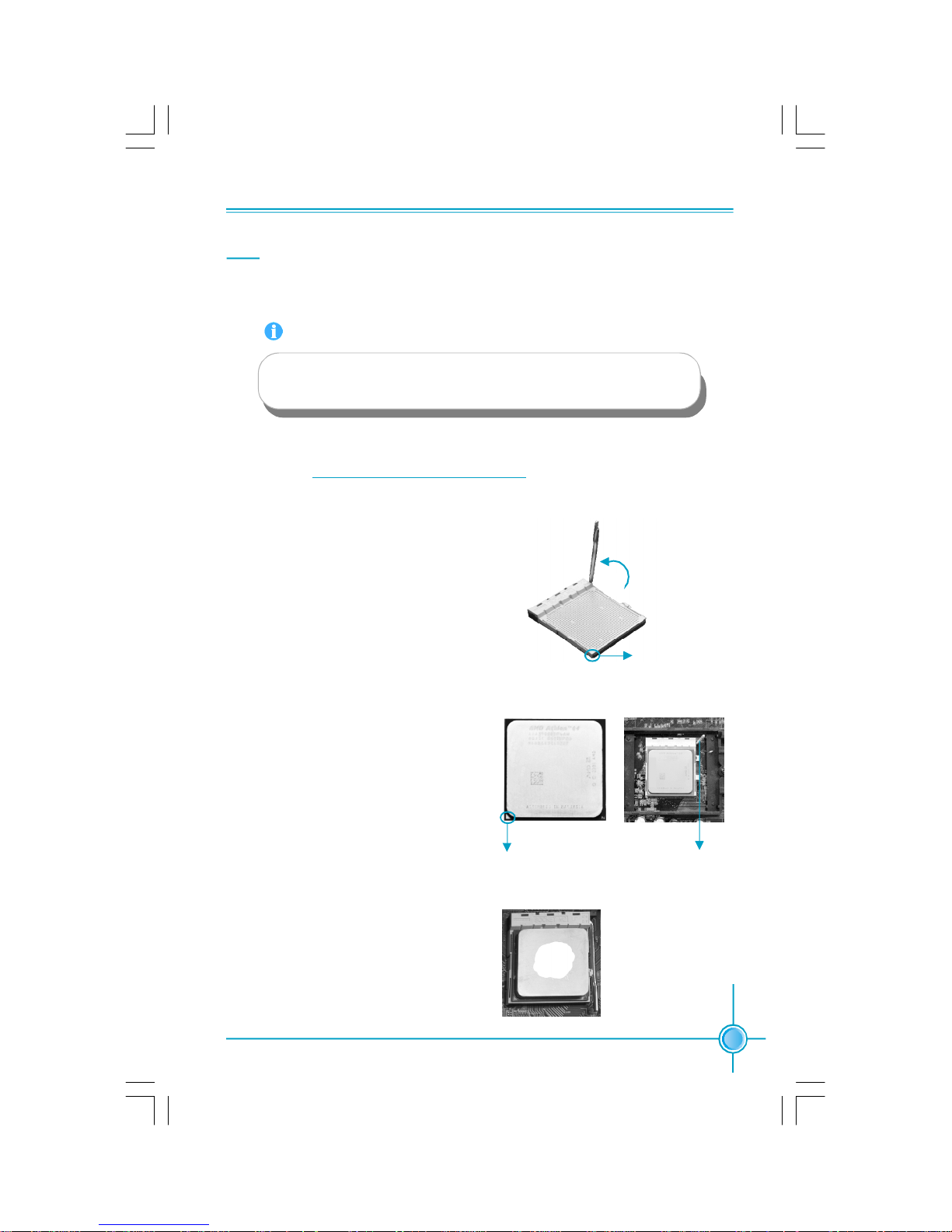
CPU
This motherboard supports AMD socket AM2 for SempronTM, Athlon
TM
64, Athlon
TM
64 FX,Athlon
TM
64 x2 Dual-Core processors and HyperTransport
TM
Technology.
1.Unlock the socket by pressing the le-
ver sideways, then lift it up to a 90
o
angle.
2.Align the cut edge to the gap in the base
of the socket. Carefully insert the CPU
into the socket until it fits in place.
3.When the CPU is in place, press it
firmly on the socket while you push
down the socket lever to secure the
CPU. The lever clicks on the side tab
to indicate that it is locked.
Installation of CPU
Follow these steps to install the CPU.
Push down the socket
lever to secure the CPU.
Cut edge
Gap in the base
For the detailed CPU vendor list qualified on this motherboard, please visit
the website: http://www.foxconnchannel.com
Attention:
The CPU pins must be properly aligned with the holes in the
socket, otherwise the CPU may be damaged.
90
o
Page 17
10
Chapter 2 Installation Instructions
1.Locate the CPU retention mecha-
nism base (surrounds the CPU
socket) (If the rentention mechanism
not be installed).
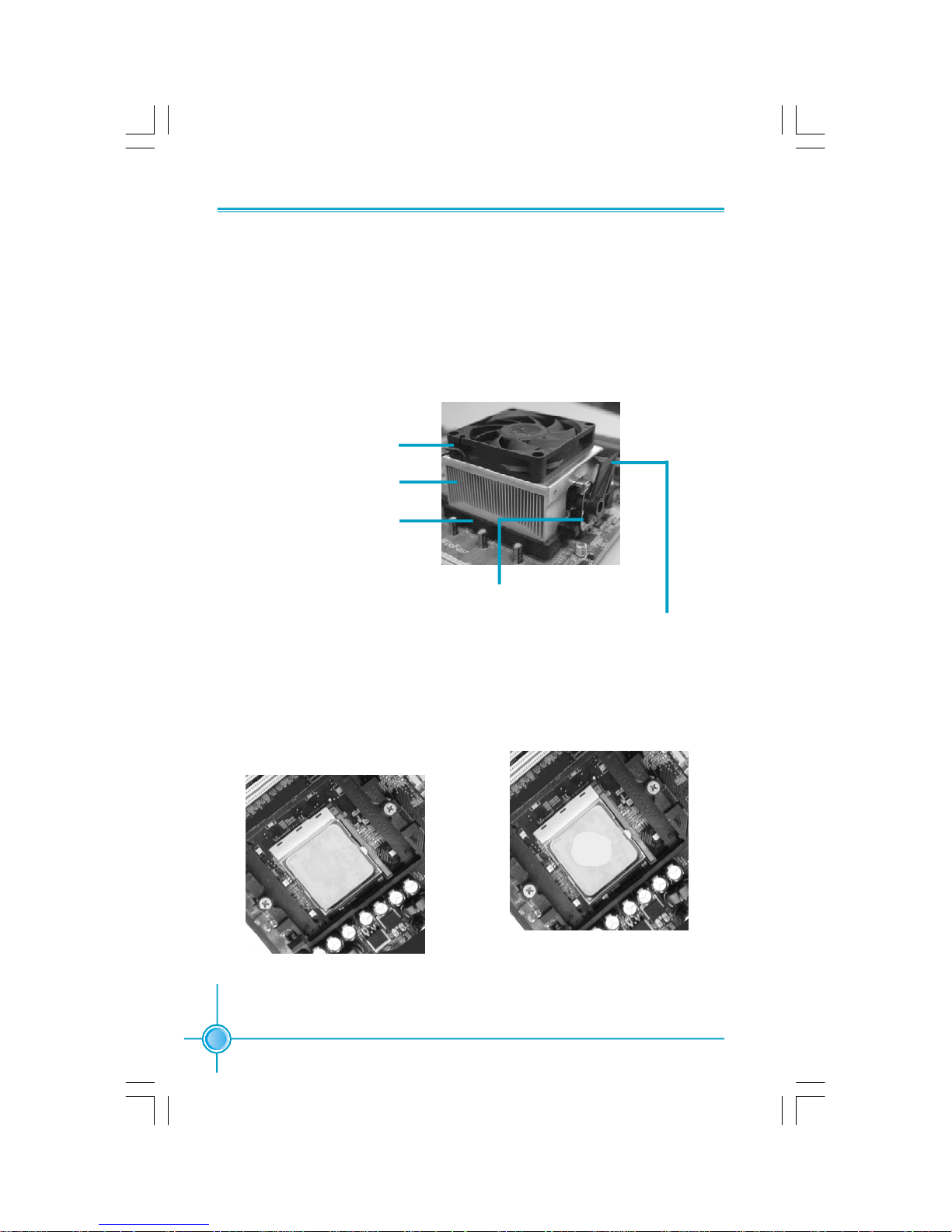
Installation of CPU Fan
New technology allows processors to run at higher and higher frequencies.
To avoid problems arising from high-speed operation, for example,
overheating, you need to install the proper fan. The following procedure is
provided for reference only, please refer to your CPU fan user guide for the
actual procedure.
2.If required, apply a light coating of
silica gel to the top of the CPU.
NOTE: The CPU heatsink may have
a pre-applied thermal compound. In
that case, the silica gel is not required.
CPU Fan
CPU Heatsink
CPU Retention Mechanism
CPU Retention Bracket
CPU Retention Lock
Page 18
11
Chapter 2 Installation Instructions
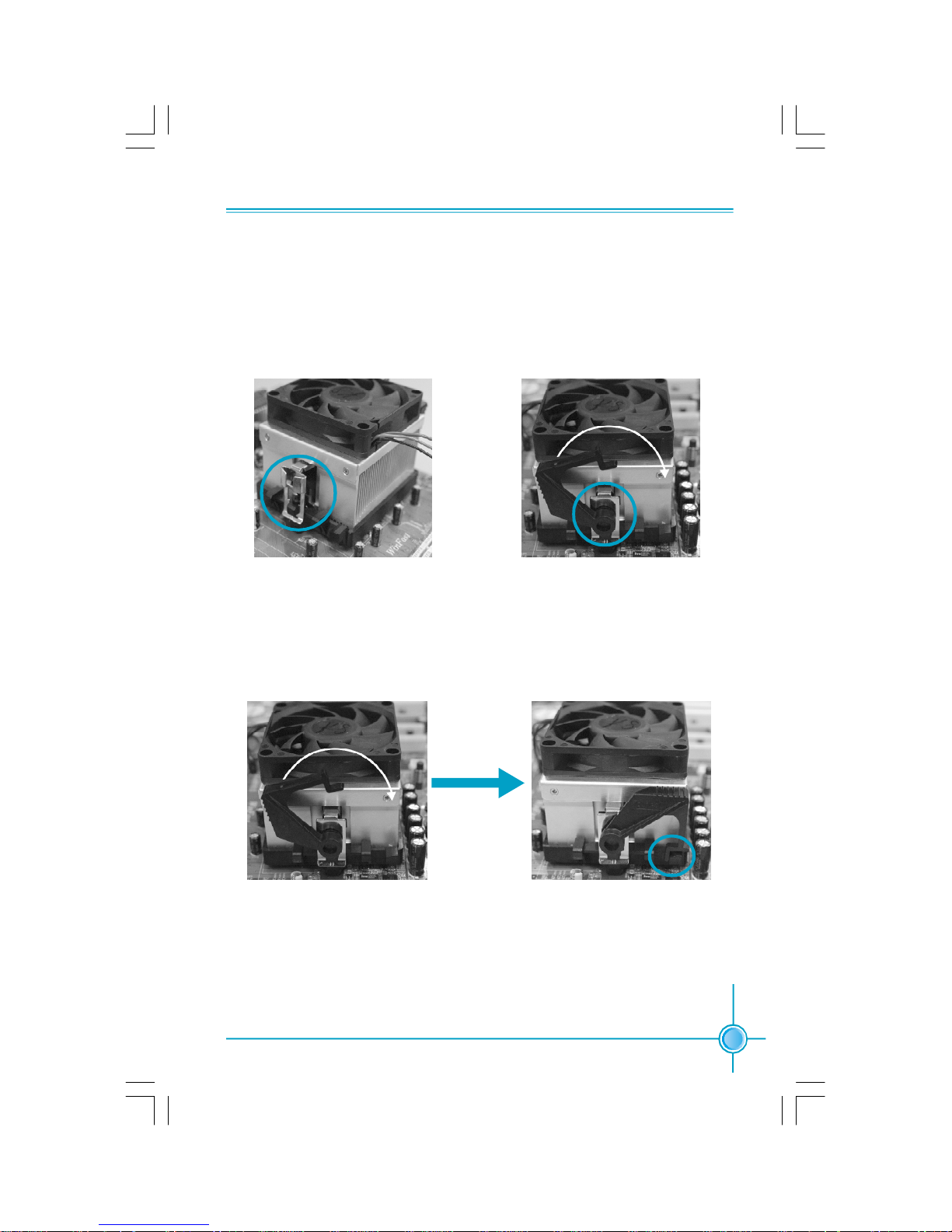
5.Push down the retention bracket lock on the retention mechanism to secure
the heatsink and fan to module base.
4.Align the other end of the reten-
tion bracket to fasten the cooling
set on the top of the retention
mechanism.
3. Place the cooling set onto the re-
tention mechanism. Attach one end
of the retention bracket to retention
mechanism.
Page 19

12
Chapter 2 Installation Instructions
6.Connect the fan’s power cable to the appropriate 3-pin terminal on the
motherboard.
Page 20
13
Chapter 2 Installation Instructions
Note:
Be sure to unplug the AC power supply before adding or re-
moving expansion cards or other system peripherals, espe-
cially the memory devices, otherwise your motherboard or the
system memory might be seriously damaged.
3.The plastic clips at both sides of the DIMM slot will lock automatically.
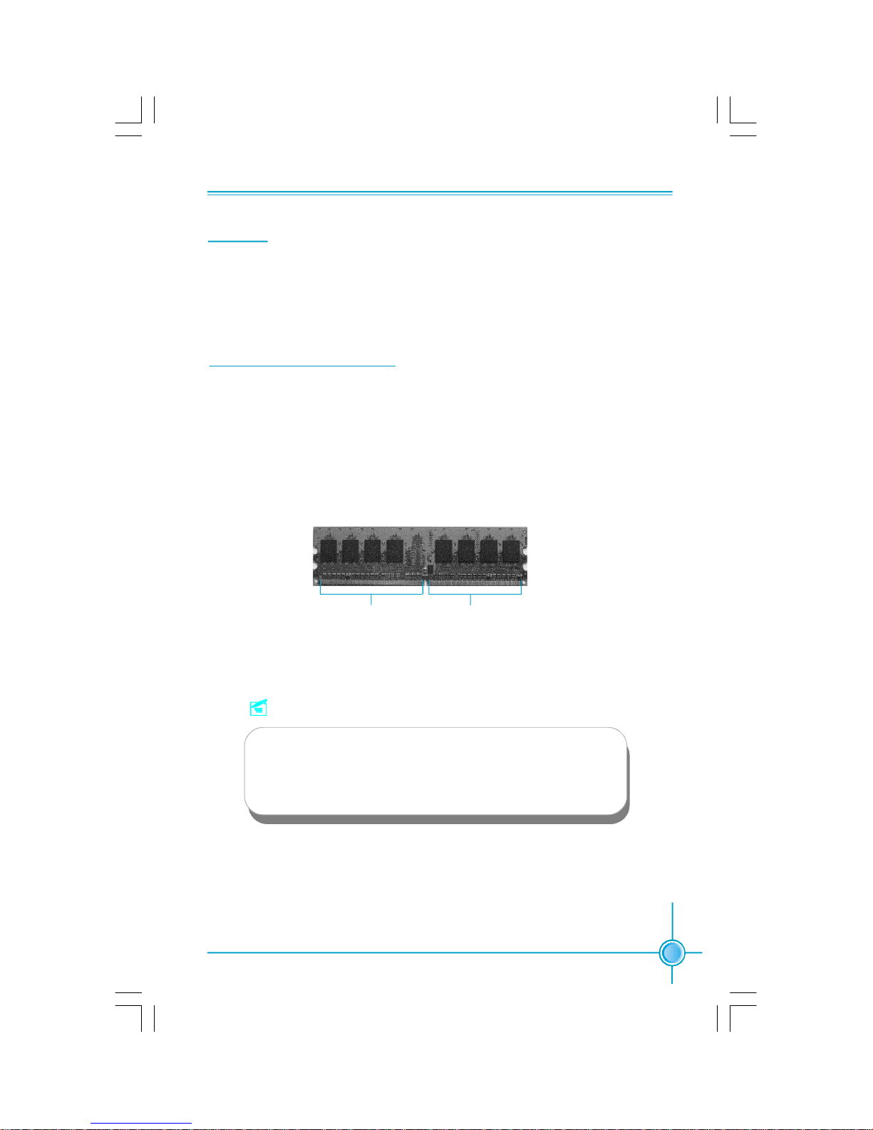
128 Pins 112Pins
Installation of DDR2 Memory
1.There is only one gap in the center of the DIMM slot, and the memory module
can be fixed in one direction only.
2.Align the memory module to the DIMM slot, and insert the module verti-
cally into the DIMM slot.
Memory
This motherboard includes four 240-pin slots with 533/667/800 MHz Dual Chan-
nel DDR2 DRAM interface. You must install at least one menory module to
ensure normal operation.
For the lastest memory modules support list, please visit the website:
http://www.foxconnchannel.com
Page 21
14
Chapter 2 Installation Instructions
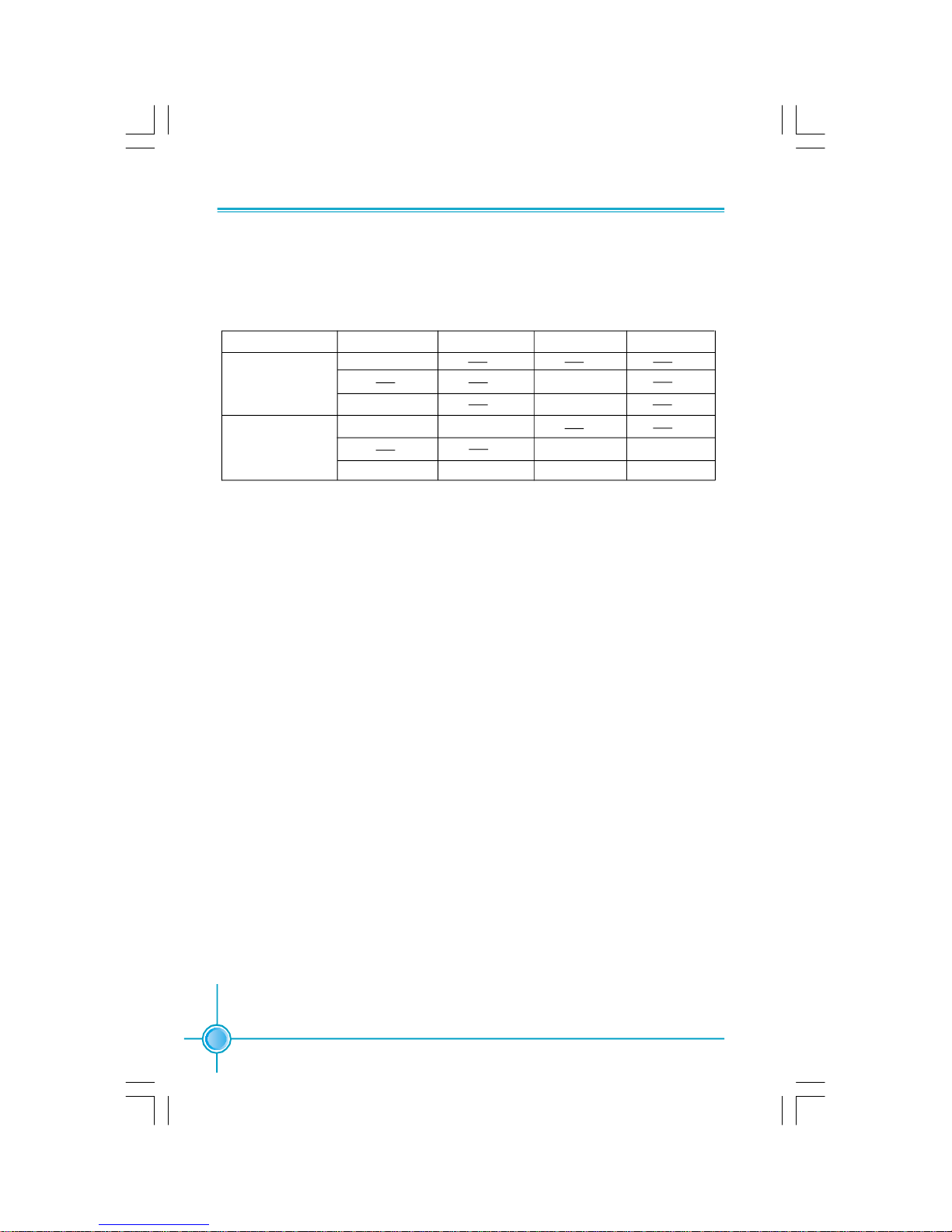
Recommended Memory Configurations
The following table list is the recommended memory configurations. Please in-
stall the memory according to the list.
Mode DIMMA0 DIMMB0 DIMMA1 DIMMB1
Populated
Signal-channel Populated
Populated Populated
Populated Populated
Dual-channel Populated Populated
Populated Populated Populated Populated
Page 22

15
Chapter 2 Installation Instructions
Power Supply
This motherboard uses an ATX power supply. In order to avoid damaging any
devices, make sure that they have been installed properly prior to connecting
the power supply.
ATX Power Connector: PWR1
PWR1 is the ATX power supply connector.
Make sure that the power supply cable
and pins are properly aligned with the
connector on the motherboard. Firmly
plug the power supply cable into the con-
nector and make sure it is secure.
ATX 12V Power Connector: PWR2
The 4 pin ATX 12V power supply connects
to PWR2 and provides power to the CPU.
11
1
ATX 12V Power Connector
12V
GND
12V
3
1 2
4
GND
13
GND
12
24
+5V
+3.3V
-12V
RSVD
+5V
GND
GND
PSON
GND
GND
+5V
+3.3V
GND
+12V
GND
+5V_AUX
+3.3V
+5V
PWROK
+12V
GND
+5V
+3.3V
Attention:
We strongly recommend you use 24-pin
power supply. If you want to use 20-pin
power supply, you need to align the ATX
power connector according to the right
picture.
Page 23

16
Chapter 2 Installation Instructions
This motherboard includes interfaces for FLOPPY, IDE devices, SATA IIdevices,
USB devices, 1394 devices, IR module, CPU fan, system fan, and others.
FLOPPY
This motherboard includes a standard FLOPPY interface, supporting 360 K, 720 K,
1.2 M, 1.44 M, and 2.88 M FDDs.
HDD connectors: PIDE & SIDE
These connectors support the UltraDMA 133/100/66 IDE hard disk ribbon cable.
Connect the cable’s blue connector to the primary (recommended) or second-
ary IDE connector, then connect the gray connector to the UltraDMA 133/100/66/
33 slave device (hard disk drive) and the black connector to the UltraDMA 133/
100/66/33 master device. If you install two hard disks, you must configure the
second drive as a slave device by setting its jumper accordingly. Refer to the
hard disk documentation for the jumper settings.
Other Connectors
Attention:
Ribbon cables are directional, therefore, make sure to always con-
nect with the cable on the same side as pin 1 of the PIDE/SIDE or
FLOPPY connector on the motherboard.
Front Panel Connector: FP
This motherboard includes one connector for con-
necting the front panel switch and LED indicator.
FPFP!
HDD_LED
RESET
PLEDPWRBTN#
1
+ -
NC
+ -
Page 24

17
Chapter 2 Installation Instructions
Hard Disk LED Connector (HDD_LED)
Attach the connector to the HDD_LED on the front panel of the case; the LED will
flash while the HDD is in operation.
Reset Switch (RESET)
Attach the connector to the Reset switch on the front panel of the case; the
system will restart when the switch is pressed.
Power LED Connector (PLED)
Attach the connector to the Power LED on the front panel of the case. The Power
LED indicates the power supply status. When the system is in S0 status, the
LED is on. When the system is in S1 status, the LED is blink. When the system
is in S3, S4, S5 status, the LED is off.
Power Switch Connector (PWRBTN#)
Attach the connector to the power button of the case. Pushing this switch allows
the system to be turned on and off rather than using the power supply button.
USB Connectors: F_USB 1, F_USB 2
Besides four USB ports on the rear panel, the series of motherboards also have
two 10-pin headers on board which may connect to the front panel USB cable to
provide additional four USB ports.
F_USB1
D5-
VCC
D4+
D4-
Empty
GND
NC
VCC
GND
D5+
1 2
9 10
F_USB2
D7-
VCC
D6+
D6-
Empty
GND
NC
VCC
GND
D7+
1 2
9 10
Fan Connectors: CPU_FAN, SYS_FAN
The fan speed of CPU_FAN and SYS_FAN can be detected and viewed in “PC
Health” section of the CMOS SETUP. These fans will be automatically turned off
after the system enters suspend mode.
SYS_FAN
SENSE
+12V
GND
1
+12V SENSEGND
1
CPU_FAN
Page 25

18
Chapter 2 Installation Instructions
Serial ATA II Connectors: SATA_1, SATA_2,
SATA_3(optional), SATA_4(optional)
The Serial ATA II connectors are used to connect the
SATA II devices to the motherboard. These connectors support the thin Serial ATA cables for primary
internal storage devices. The current SATA interface
allows up to 300MB/s data transfer rate.
Speaker Connector: SPEAKER OUT (optional)
The speaker connector is used to connect speaker
of the chassis.
IrDA Connector: IR
The IrDA infrared transmission allows your computer
to send and receive data via an infrared ray. The
relevant parameters for the BIOS Integrated Periph-
erals should be set prior to using this function.
IR
+5V
GND
IRRX
IRTX
Empty
1
10 9
Audio Connectors: CD_IN, AUX_IN(optional)
CD_IN, AUX_IN is Sony standard CD audio connectors, to receive audio input
from the CD-ROM, attach its audio connector to the CD_IN/AUX_IN audio con-
nectors on the motherboard.
CD_IN
CD_R
GND
CD_L
1
AUX_IN
AUX_R
GND
AUX_L
1
1394 Connector(optional): F_1394_1(optional)
The 1394 expansion cable can be connected to either the front (provided that the front panel of your
chassis is equipped with the appropriate interface)
or the rear panel of the chassis.
Empty
F_1394 _1
TPB+
TPA+
+12V
GND
TPB-
+12V
GND
GND
TPA-
2 1
1
SPK(Pull high) SPKJ
Empty
NC
SPEAKER OUT
GND
GND
GND
TX+
TX-
RX+
RX-
1
SATA_1/2/3/4
Page 26

19
Chapter 2 Installation Instructions
Chassis Intruder Connector : INTR
The connector connects to the chassis security switch on the case. The system can
detect the chassis intrusion through the status of this connector. Please set the reference items in BIOS and save the setting.
S/PDIF Out Connector: SPDIF_01
The S/PDIF out connector is capable of providing digital audio to external speaker or
compressed AC3 data to an external Dolby
digital decoder.
Note: The empty pin of SPDIF cable should
be aligned to empty pin of S/PDIF out
connector.
1
INTRUDERJ
GND
INTR
1
GND
SPDIF_01
1
SPDIF_OUT
Empty
5V
The audio connector provides two kinds of
audio output choices: the Front Audio, the
Rear Audio. Front Audio supports re-tasking
function. Their priority is the same.
For -8 models (optional)
SENSE_SEND
PORT1_L
PORT1_R
PORT2_L
F_AUDIO1
AUD_GND
PRESENCEJ
PORT2_R SENSE1_RETURN
Empty
SENSE2_RETURN
1
Front Audio Connector: F_AUDIO1
(for -6 models)
The audio port includes two parts – the Front
Audio and Rear Audio. Their priority is sequenced from high to low (Front Audio to Rear
Audio). If headphones are plugged into the
front panel of the chassis (using the Front
Audio), then the Line Out (Rear Audio) on the
rear panel will not work. If you do not want to
use the Front Audio, pin 5 and 6, pin 9 and
10 must be short, and then the signal will be
sent to the rear audio port.
F_AUDIO1
MIC_GND
MIC_IN
+5VAC
MIC_PWR
AUD_RET_R
AUD_OUT_R
EMPTY
AUD_OUT_L
AUD_RET_L
1 2
9 10
NC
Page 27

20
Chapter 2 Installation Instructions
Addtional COM Connector: COM2
This motherboard provides an additional
serial COM connector for your machine.
Connect one side of a switching cable to the
connector, then attach the serial COM device
to the other side of the cable.
SOUT
GND
RLSD
RI#
DTR#
DSR#
SIN
9 10
1 2
CTS#
RTS#
COM2
Empty
Page 28

21
Chapter 2 Installation Instructions
Expansion Slots
PCI Slots
The expansion cards can be installed in the two PCI slots. When you install or
remove such cards, please make sure that the power plug has been unplugged
from the power supply. Please read carefully the instructions provided for such
cards, then install and set the necessary hardware and software for such cards,
such as the jumper or BIOS settings.
This motherboard includes two 32-bit Master PCI bus slots,one PCI Express x1
slot and onePCI Express x16 Graphics slot.
P
PCI Express Slots
PCI Express will offer the following design advantages over the PCI and AGP
interface:
-Compatible with existing PCI drivers and software and Operating Systems.
-High Bandwidth per Pin. Low overhead. Low latency.
-PCI Express supports a raw bit-rate of 2.5 Gb/s on the data pins. This
results in a real bandwidth per pair of 250 MB/s.
-A point to point connection, allows each device to have a dedicated connec-
tion without sharing bandwidth.
-Ability to comprehend different data structure.
-Low power consumption and power management features.
PCI Express will take two forms, x16 and x1 PCI Express slots. Whereas the x16
slot is reserved for graphic/video cards, the x1 slots are designed to accommo-
date less bandwidth-intensive cards, such as a modem or LAN card.
The difference in bandwidth between the x16 and x1 slots are notable to be
sure, with the x16 slot pushing 4GB/sec (8GB/sec concurrent) of bandwidth,
and the x1 PCI Express slot offering 250 MB/sec.
If a performance graphics card was installed into x16 PCI
Express slot, 2X12 pin power supply was strongly recom-
mended.
Note:
Page 29

22
Chapter 2 Installation Instructions
Installing an expansion card
1.Before installing the expansion card, please make sure that the power sup-
ply is switched off or the power cord is unplugged. Please read the docu-
mentation that came with it and make the necessary hardware settings for
the card.
2.Remove the bracket facing the slot that you intend to use. Keep the screws
for later use.
3.Align the card connector with the slot and press firmly until the card is
completely seated on the slot.
4.Secure the card to the chassis with the screw you removed earlier.
Page 30

23
Chapter 2 Installation Instructions
Jumpers
Users can change the jumper settings on this motherboard if necessary. This
section explains how to use the various functions of this motherboard by changing the jumper settings. Users should read the following contents carefully prior
to modifying any jumper settings.
Description of Jumpers
1.For the jumpers on this motherboard, pin 1 can be identified by the silkscreen printed “ ” next to it. However, in this manual, pin 1 is simply
labeled as “1”.
2.The following table provides some explanations of the jumper pin settings.
Users should refer to the table while adjusting jumper settings.
Clear CMOS Jumper: CLS_CMOS
This motherboard uses the CMOS RAM to store all
the set parameters. The CMOS can be cleared by
removing the CMOS jumper. Reference the follow-
ing process.
1. Turn off the AC power supply and short pins 1 and
2 on the jumper.
2. Return the jumper to the normal setting (locking
pins 2 and 3 together with the jumper cap).
3. Turn on the system. The BIOS is returned to the
default settings.
Jumper Diagram Definition Description
1-2 Set pin 1 and pin 2 closed
2-3 Set pin 2 and pin 3 closed
Closed Set the pin closed
Open Set the pin opened
1
1
1
1
1
1
Warning:
1.Disconnect the power cable before adjusting the jumper
settings.
2.DO NOT clear the CMOS while the system is turned on.
CLS_CMOS
Normal
(default)
Clear
1
2
3
1
2
3
Page 31

24
Chapter 2 Installation Instructions
Starting up for the first time
1.After making all the connections, replace the system case cover.
2.Make sure that all switches are turned off.
3.Turn on the devices in the following order.
a. Monitor
b. External SCSI devices (starting with the last device on the chain)
c. System power
4. After powering on, LED on the system front panel case lights up. For ATX
power supplies, the system LED lights up when you press the ATX power
switch. If your monitor complies with green standards or if it has a power
standby feature, the monitor LED may light up or switch between orange and
green after the system LED turns on. The system then enters the Power-On
Self Test (POST) routines. While the tests are running, the BIOS beeps or
additional messages appear on the screen. If you do not see anything within
30 seconds from the time you turned on the power, the system may have
failed a power-on test. Check the jumper settings and connections or call
your retailer for assistance.
5.After the POST routines are completed, press the <Del> key to access the
BIOS Setup Utility. For detailed instructions, please refer to Chapter 3.
Powering off the computer
1.Using the OS shut down function
If you use windows 98/ME/2000/XP, click Start and select Shut Down, then
click the OK button to shut down the computer. The power supply should
turnoff after Windows shuts down.
2. Using the dual function power switch
While the system is ON, pressing the power switch for less than 4 sec-
onds puts the system in sleep mode or soft-off mode, depending on the
BIOS setting. Pressing the power switch for more than 4 seconds lets the
system enter the soft-off mode regardless of the BIOS setting.
Page 32

This chapter tells how to change system settings through the
BIOS Setup menus. Detailed descriptions of the BIOS param-
eters are also provided.
You have to run the Setup Program when the following cases
occur:
1.An error message appears on the screen during the
system POST process.
2.You want to change the default CMOS settings.
This chapter includes the following information:
v Enter BIOS Setup
v Main Menu
v Standard CMOS Features
v Advanced BIOS Features
v Advanced Chipset Features
v Integrated Peripherals
v Power Management Setup
v PnP/PCI Configurations
v PC Health Status
v Frequency/Voltage Control
v Load Fail-Safe Defaults
v Load Optimized Defaults
v Set Supervisor/User Password
v Save & Exit Setup
v Exit Without Saving
Chapter
3
3
Page 33

26
Chapter 3 BIOS Description
Enter BIOS Setup
The BIOS is the communication bridge between hardware and software,
correctly setting up the BIOS parameters is critical to maintain optimal system
performance. Power on the computer, when the following message briefly
appears at the bottom of the screen during the POST (Power On Self Test),
press the <Del> key to enter the Award BIOS CMOS Setup Utility.
Press TAB to show POST screen, DEL to enter SETUP, ESC to enter Boot Menu
Main Menu
The main menu allows you to select from the list of setup functions and two exit
choices. Use the arrow keys to select among the items and press <Enter> to
accept or go to the sub-menu.
The items in the BIOS Setup main menu are explained below:
Standard CMOS Features
The basic system configuration can be set up through this menu.
Advanced BIOS Features
The advanced system features can be set up through this menu.
Main Menu
Note:
We do not suggest that you change the default parameters in the
BIOS Setup, and we shall not be responsible for any damage that
results from any changes that you make.
Page 34

27
Chapter 3 BIOS Description
Advanced Chipset Features
The values for the chipset can be changed through this menu, and the sys-
tem performance can be optimized.
Integrated Peripherals
All onboard peripherals can be set up through this menu.
Power Management Setup
All the items of Green function features can be set up through this menu.
PnP/PCI Configurations
The system’s PnP/PCI settings and parameters can be modified through
this menu.
PC Health Status
This will display the current status of your PC.
Frequency/Voltage Control
Frequency and voltage settings can be adjusted throughthis menu.
Load Fail-Safe Defaults
The default BIOS settings can be loaded through this menu.
Load Optimized Defaults
The optimal performance settings can be loaded through this menu, however,
the stable default values may be affected.
Set Supervisor/User Password
The supervisor/user password can be set up through this menu.
Save & Exit Setup
Save CMOS value settings to CMOS and exit setup.
Exit Without Saving
Abandon all CMOS value changes and exit setup.
Page 35

28
Chapter 3 BIOS Description
Standard CMOS Features
This sub-menu is used to set up the standard CMOS features, such as the
date, time, HDD model and so on. Use the arrow keys select the item to set
up, and then use the <PgUp> or <PgDn> key to choose the setting values.
Date
This option allows you to set the desired date (usually as the current date)
with the <day><month><date><year> format.
day weekday from Sun. to Sat., defined by BIOS (read-only).
month month from Jan. to Dec.
date date from 1st to 31st, can be changed by using the keyboard.
year year, set up by users.
Time
This option allows you to set up the desired time (usually as the current time)
with <hour><minute><second> format.
IDE Channel 0/1 Master/Slave
These categories identify the HDD types of 2 IDE channels installed in the
computer system. There are three choices provided for the Enhanced IDE BIOS:
None, Auto, and Manual. “None” means no HDD device is installed or set; “Auto”
indicates the system can automatically detect and configure the hard disk when
booting up; If it fails to find a device, choose “Manual” and change Access Mode
to “CHS”, then manually configure the drive by entering the characteristics of the
drive directly from the keyboard and pressing <Enter>:
Standard CMOS Features Menu
Cylindernumber of cylinders Head number of heads
Precompwrite pre-compensation Landing Zone Landing Zone
Sector number of sectors
Page 36

29
Chapter 3 BIOS Description
Award (Phoenix) BIOS can support 4 HDD modes: CHS, LBA and Large or
Auto mode.
CHS For HDD<528MB
LBA For HDD>528MB & supporting LBA (Logical Block Addressing)
Large For HDD>528MB but not supporting LBA
Auto Recommended mode
Drive A
This option allows you to select the kind of FDD to be installed, including
[None], [360K, 5.25in], [1.2M, 5.25in], [720K, 3.5in], [1.44M, 3.5in] and [2.88
M, 3.5in].
Halt On
This category determines whether or not the computer will stop if an error is
detected during powering up.
All Errors Whenever the BIOS detects a nonfatal error, the
system will stop and you will be prompted.
No Errors The system boot will not stop for any errors that may
be detected.
All, But Keyboard The system boot will not stop for a keyboard error;
but it will stop for all other errors.
All, But Diskette The system boot will not stop for a diskette error; but
it will stop for all other errors.
All, But Disk/Key The system boot will not stop for a keyboard or a
disk error, but it will stop for all other errors.
Memory
This is a Displays-Only Category, determined by POST (Power On Self Test)
of the BIOS.
Base Memory The BIOS POST will determine the amount of base
(or conventional) memory installed in the system.
Extended Memory The BIOS determines how much extended
memory is present during the POST.
Total Memory Total memory of the system.
Page 37

30
Chapter 3 BIOS Description
Advanced BIOS Features
vRemovable Device Priority
This option is used to remove the priority for removable device startup. After
pressing <Enter>, you can remove the removable device using the <PageUp>/
<PageDn> or Up/ Down arrow keys, and change the removable device pri-
ority using <+> or <->. To exit this option, press <Esc>.
vHard Disk Boot Priority
This option is used to select the priority for HDD startup. After pressing
<Enter>, you can select the HDD using the <PageUp>/<PageDn> or Up/Down
arrow keys, and change the HDD priority using <+> or <->. To exit this option,
press <Esc>.
vCD-ROM Boot Priority
This option is used to select the priority for CD-ROM startup. After pressing
<Enter>, you can select the CD-ROM using the <PageUp>/<PageDn> or Up/
Down arrow keys, and change the CD-ROM priority using <+> or <->. To exit
this option, press <Esc>.
vNetwork Boot Priority
This option is used to select the priority for network boot startup. After press-
ing <Enter>, you can select the network boot using the <PageUp>/<PageDn>
or Up/Down arrow keys, and change the network boot priority using <+> or <
->. To exit this option, press <Esc>.
vVirus Warning
This option is used to set up the virus warning message for the IDE HDD boot
sector. When enabled, a warning message will appear on the screen if any
program intends to write information to the boot sector.
Note: Such function provides protection to the startup sector only; it does
not protect the entire hard disk.
Advanced BIOS Features Menu
Page 38

31
Chapter 3 BIOS Description
vCPU Internal Cache
This option is used to turn on or off the CPU L1 and L2 cache.
vExternal Cache
This option is used to turn on or off the CPU external cache. The available
setting values are: Disabled and Enabled. Leave this item at the default value
for better performance.
vFirst/Second/Third Boot Device
This option allows you to set the boot device sequence. The available setting
values are: Floppy, LS120, Hard Disk, CDROM, ZIP100, USB-FDD, USB-ZIP,
USB-CDROM, Legacy LAN, NVIDIA Boot Age and Disabled.
vBoot Other Device
With this item enabled, the system will search all other possible locations if it
fails to find one in the devices specified under the first, second and third boot
devices.
vBoot Up Floppy Seek
If this option is enabled, BIOS will activate the floppy drive during the system
boot and the drive’s indicator will flash after the activation. The magnetic
head will move back and forth from A to B.
vBoot Up NumLock Status
This option defines if the keyboard Num Lock key is active when your system
is started.
vTypematic Rate Setting
If this option is enabled, you can use the following two items to see the
typematic rate and the typematic delay settings for your keyboard.
vTypematic Rate (Chars/Sec)
Use this option to define how many characters per second a held-down
keygenerated.
vTypematic Delay (Msec)
Use this option to define how many milliseconds must elapse before a
held-down key begins generating repeat characters.
vSecurity Option
When it is set to Setup, a password is required to enter the CMOS Setup
screen; when it is set to System, a password is required not only to enter
CMOS Setup, but also to start up your PC.
Page 39

32
Chapter 3 BIOS Description
vAPIC Mode
This option is used to enable or disable APIC mode.
vMPS Version Control For OS
This option is used to set up the version of MPS Table used in NT4.0 OS.
vOS Select For DRAM > 64MB
This option is only required if you have installed more than 64 MB of memory
and you are running the OS/2 operating system. Otherwise, leave this option
at the default.
vFull Screen LOGO Show
This option allows you to enable or disable the full screen logo.
vSmall Logo (EPA) Show
This option allows you to enable or disable the EPA logo.
Page 40

33
Chapter 3 BIOS Description
Advanced Chipset Features
Advanced Chipset Features Menu
vFrame Buffer Size
This item is used to set the VGA frame buffer size.
Note: This function does not work when the external display card is used.
vK8<->NB/NB-->SB/NB<--SB HT Speed
These options are used to set the bandspeed of the link’s transmitter of K8
<->NB/NB-->SB/NB<--SB .
vK8<->NB/NB<->SB HT Width
These options are used to set the bandwidth of the link’s transmitter of K8
<->NB/NB<->SB.
vErr94 Enh
This option is used to set Err94 Enh.
vDRAM Configuration
Press <Enter> to set the items about DRAM Configuration.
vSSE/SSE2 Instructions
It is used to set enable or disable Intel SSE/SSE2 instructions.
vSystem BIOS Cacheable
Select “Enabled” to allow catching of the system BIOS which may improve per-
formance. If any other program writes to this memory area, a system error
may result.
Page 41

34
Chapter 3 BIOS Description
vTime Mode
This item is used to set timing mode.
vMemory clock Value or Limit
This option is used to set memory clock value or limit.
vDQS Timing Training Control
This option controls the DQS timing training .
vCKE base Power down mode
This option is used to set the CKE base Power dowm mode.
vCKE based Power dowm Control
This option controls the CKE based power down.
vMemory hole Remapping
This item is used to enalbe or disable the memory hole remapping.
vAuto Optimize Bottom IO
This item is used to set the auto optimize bottom IO.
vBottom of 32-bit [31:24] IO
This item is used to set Bottom of 32-bit [31:24] IO.
DRAM Configuration Menu
Page 42

35
Chapter 3 BIOS Description
Integrated Peripherals
Integrated Peripherals Menu
vIDE Function Setup
Press Enter to set the items about IDE Function.
vRAID Config
Press <Enter> to set the items of Raid configuration.
vOnboard Device
Press <Enter> to set the items of onboard device.
vIDE HDD Block Mode
This option is used to set whether the IDE HDD Block Mode is allowed. The
available setting values are: Disabled and Enabled.
vOnboad FDC Controller
This option is used to set whether the onboard FDC controller is enabled.
vOnboard Serial Port 1/2
This option is used to assign the I/O address and interrupt request (IRQ)
for the onboard serial port 1/2.
Note: Do not try to set the same values for serial port 1 and 2.
vUART Mode Select
Use this option to select the UART mode. The setting values include Normal,
IrDA, ASKIR and SCR. The setting value is determined by the infrared module
installed on the board.
vUR2 Duplex Mode
This option is available when UART 2 mode is set to either ASKIR or IRDA. This
option enables you to determine the infrared (IR) function of the onboard infrared chip. The available setting values are: Half and Full.
Page 43

36
Chapter 3 BIOS Description
vOnboard Parallel Port
This option is used to assign the I/O address and interrupt request (IRQ) for
onboard parallel port controller. The setting values include: Disabled, 378/
IRQ7, 278/IRQ5 and 3BC/IRQ7.
vParallel Port Mode
Select an address and corresponding interrupt for the onboard parallel port.
The setting values include SPP, EPP, ECP, ECP+EPP.
vECP Mode Use DMA
Select a DMA channel for the parallel port when using the ECP mode.This field
is only configurable if Parallel Port Mode is set to ECP.
Page 44

37
Chapter 3 BIOS Description
IDE Function Menu
vIDE Primary/Secondary Master/Slave PIO
These four items let you assign which kind of PIO (Programmer Input/Output)
is used by IDE devices. Choose “Auto” to let the system auto detect which PIO
mode is best, or select a PIO mode from 0-4.
vPrimary/Secondary Master/Slave UItraDMA
UItraDMA technology provides faster access to IDE devices. If you install a
device that supports UItraDMA, change the appropriate items on this list to
Auto. The available setting values are: Disabled and Auto.
vIDE DMA transfer access
This option is used to enable or disable IDE DMA transfer access.
vSerial-ATA Cotroller
This option is used to enable or disable Serial-ATA cotroller.
vIDE Prefetch Mode
This option is used to enable or disable IDEprefetch mode.
vOnChip IDE Channel 0/1
This option is used to set the onchip IDE channel 0/1. The available setting
are: Disabled and Enabled.
Page 45

38
Chapter 3 BIOS Description
v RAID Enable
This option is used to disable or enable the RAID function. When enabled,
the following grayed items will be activated.
vSATA 1/2 Primary/Secondary RAID
These feature allow users to enable or disable the RAID function for each
SATA hard disk drive.
RAID Config Menu
Page 46

39
Chapter 3 BIOS Description
vOnchip USB
This option is used to set whether the USB Controller is enabled.
vUSB Memory Type
This option is used to set the USB Memory type.
vUSB Keyboard Support
This option is used to set whether the USB keyboard controller is enabled in a
legacy operating system (such as DOS). The available setting values are:
Disabled and Enabled.
vUSB Mouse Support
This option is used to set whether the USB mouse controller is enabled in a
legacy operating system (such as DOS). The available setting values are:
Disabled and Enabled.
vAC97/HD Audio
This option is used to set whether onboard Azalia/AC97 Audio is enabled. The
available setting values are: Disabled and Auto.
vMAC LAN
This option is used to set whether MAC LAN device is enalbed.
vMAC Media Interface
This option is used to set MAC Media Interface.
vMAC LAN Boot ROM
This option is used to decide whether to invoke the boot ROM of the MAC LAN
chip.
Onboard Device Setup
Page 47

40
Chapter 3 BIOS Description
Power Management Setup
vACPI function
ACPI stands for “Advanced Configuration and Power Interface”. ACPI is a
standard that defines power and configuration management interfaces between an operating system and the BIOS. In other words, it is a standard that
describes how computer components work together to manage system
hardware. In order to use this function the ACPI specification must be supported by the OS (for example, Windows2000 or WindowsXP).
vACPI Suspend Type
This option is used to set the energy saving mode of the ACPI function.
When you select “S1 (POS)” mode, the power will not shut off and the
supply status will remain as it is, in S1 mode the computer can be resumed
at any time. When you select “S3 (STR)” mode, the power will be cut off after
a delay period. The status of the computer before it enters STR will be saved
in memory, and the computer can quickly return to the previous status when
the STR function wakes. When you select “S1 & S3” mode, the system
will automatically select the delay time.
vPower Management
This option is used to set the power management scheme. Available settings
are: User Define, Min Saving and Max Saving.
vVideo Off Method
This option is used to define the video off method. “Blank Screen” mode
means that after the computer enters power saving mode, only the monitor
will close, however, the vertical and horizontal scanning movement of the screen
continues. When you select the “V/H SYNC + Blank” mode the vertical and horizontal
scanning movement of screen stops when the computer enters power saving
mode. “DPMS Supported” mode is a new screen power management system,
and it needs to be supported by the monitor you’re using.
Power Management Setup Menu
Page 48

41
Chapter 3 BIOS Description
vHDD Power Down
This option is used to turn off hard disk power if the hard disk is idle for a given
period of time. The setting values are Disabled and 1Min-15Min.
vHDD Down In Suspend
This option is used to define the continuous HDD idle time before the HDD
enters power saving mode. The setting values are Disabled and Enabled.
vSoft-Off by PBTN
This option is used to set the power down method.
vWOL(PME#) From Soft-Off
When set to Enable, the feature allows your system to be awakened from the
power saving modes through any event on PME (Power Management Event)
vWOR(RI#) From Soft-Off
If this item is enabled, it allows the system to resume from a software power
down or power saving mode whenever there is an incoming call to an in stalled fax/modem. This function needs to be supported by the relevant hard ware and software.
vCase Open Warning
This option is used to enable or disable case open warning function.
vPower-On by Alarm
This option is used to enable or disable the feature of booting up the system
on a scheduled time/date. The setting values are Disabled and Enabled.
vDate of Month Alarm
When the Power-On by Alarm set as “Enabled”, this option will be modified. It
is used to set the timing for the start-up date. The setting values contain 0 - 31.
vTime (hh: mm: ss) Alarm
When the Power-On by Alarm set as “Enabled”, this option will be modified. It
is used to set the timing for the start-up date. The setting values contain hh: 0-
23; mm: 0-59; ss: 0-59.
vPOWER ON Function
This option is used to set the POWER ON function.
vKB Power On Password
This item is used to set Keyboard Power On Password.
vHot Key Power On
This item is used to set Hot Key Power On.
vPWRON Ater PWR-Fail
This option is used to set the PWRON after PWR-Fail.
Page 49

42
Chapter 3 BIOS Description
PnP/PCI Configurations
vInit Display First
This item is used to set which display device will be used first when your PC
starts up.
vReset Configuration Data
This option is used to set whether the system is permitted to automatically
distribute IRQ DMA and I/O addresses each time the machine is turned on.
The setting values are: Disabled and Enabled.
vResources Controlled By
This option is used to define the system resource control scheme. If all cards
you use support PnP, then select Auto (ESCD) and the BIOS will automatically
distribute interruption resources. If the ISA cards you installed not supporting PnP, you will need to select “Manual” and manually adjust interruption
resources in the event of hardware conflicts. However, since this motherboard
has no ISA slot, this option does not apply.
vIRQ Resources
Press the <Enter> key, then manually set IRQ resources.
vPCI/VGA Palette Snoop
If you use a nonstandard VGA card, use this option to solve graphic acceleration card or MPEG audio card problems (e.g., colors not accurately displayed).
vMaximum Playload Size
This item is used to set maximum payload size for PCI Express device.The
unit is byte.
PnP/PCI Configurations Menu
Page 50

43
Chapter 3 BIOS Description
PC Health Status
vShutdown Temperature
This option is used to set the system temperature upper limit. When the
temperature exceeds the setting value, the motherboard will automatically
cut off power to the computer.
vCPU Vcore, +3.3V, +5V, +12V, +5VSB, Voltage Battery, Current CPU
Temperature, Current SYS Temperature, CPU Fan Speed, System Fan Speed
These items display the current status of all the monitored hardware device/
components such as CPU voltage, temperatures and all fan’s speeds.
vSmart Fan Control
This option is used to enable or disable smart fan function. The setting values
are Disabled and Enabled.
PC Health Status Menu
Page 51

44
Chapter 3 BIOS Description
Frequency/Voltage Control
vVDIMM Voltage Select
This option is used to select the VDIMM voltage.
v1.2V Core Voltage Select
This option is used to select the 1.2V Core voltage.
vVcore Voltage Select
This option is used to select the Vcore voltage.
Frequency/Voltage Control menu
Page 52

45
Chapter 3 BIOS Description
Load Fail-Safe Defaults
Select this option and press <Enter>, it will pop up a dialogue box to allow you
to install fail-safe defaults for all appropriate items in the Setup Utility. Select
<Y> and press <Enter> to load the defaults. Select <N> and press <Enter> to not
load. The defaults set by BIOS have set the basic functions of system in order to
ensure the stability of system. But if your computer fails to properly work, you
may load the default to make the system recover normal, then carry out failure
testing in next step. If you only want to load the default for a specific option, you
can select this option and press the <F6> key.
Set Supervisor/User Password
The preferential grade of supervisor password is higher than user password.
You can use supervisor password to start into system or enter into CMOS setting program to amend setting. You can also use user password to start into
system, or enter into CMOS setting menu to check, but if you have set supervisor
password, you cannot amend the setting.
Highlight the item Set Supervisor / User Password on the main menu and press
<Enter>. The following password dialog box appears:
Enter Password:
Enter your password, not exceeding 8 characters, then press <Enter>, you will
be prompted to confirm the password, type in the password again and press
<Enter>.
If you are deleting a password that is already installed, just press <Enter> when
the password dialog box appears, and the screen will show a message that
indicates this password has been disabled. In this case, you can freely enter
into system and CMOS setting program.
PASS WORD DISABLED!!!
Press any key to continue...
Load Optimized Defaults
Select this option and press <Enter>, it will open a dialogue box that lets you
install the optimized defaults for all appropriate items in the Setup Utility. Select
<Y> and press <Enter> to load the optimized defaults. Select <N> and press
<Enter> to not install. The defaults set by BIOS have set the optimized performance parameters of system to improve the performances of system
components. But if the optimized performance parameters to be set cannot be
supported by your hardware devices, you can cause fatal errors or instability. If
you only want to load the optimized defaults for a specific option, you can select
this option and press the <F7> key.
Page 53

46
Chapter 3 BIOS Description
Save & Exit Setup
Select this option and press <Enter>, the following message will appear on the
screen:
SAVE to CMOS and EXIT (Y/N)?
Press <Y> to save the changes that you have made in the Setup Utility and exit
the Setup Utility; press <N>/<ESC> to return to the main menu.
Exit Without Saving
Select this option and press <Enter>, it will show the following message on the
screen:
Quit Without Saving (Y/N)?
Press <Y> to discard any changes that you have made in the Setup Utility and
exit the Setup Utility; press <N>/<ESC> to return to the main menu.
Under the menu “Advanced BIOS Features Setup”, if you select “System” in
Security Option, the screen will prompt you to enter password once the system
is started or you want to enter CMOS setting program. If the password is wrong,
it will refuse you to continue.
Under the menu “Advanced BIOS Features Setup”, if you select “Setup” in Security Option, the screen will prompt you to enter password only when you enter
CMOS setting program.
Page 54

4
4
Chapter
The utility CD that came with the motherboard contains useful
software and several utility drivers that enhance the mother-
board features.
This chapter includes the following information:
v Utility CD content
v Installing drivers
v Installing Utilities
Page 55

48
Chapter 4 Driver CD Introduction
Utility CD content
This motherboard comes with one Utility CD. To begin using the CD, simply insert
the CD into your CD-ROM driver. The CD will automatically display the main menu
screen.
1. Install Driver
Using this option to install all the drivers for your motherboard. You should
install the drivers sequentially, from first to last.
A. NVIDIA Chipset Driver
B. Realtek Audio Driver
C. NVIDIA VGA Driver
2. Utility
Use this option to install additional software programs.
A. TIGER ONE
B. NVIDIA nTune
C. Microsoft DirectX 9.0
D. Adobe Acrobate Reader
E.Norton Internet Security
3. Manual
Click to browse the content of manual.
Page 56

49
Chapter 4 Driver CD Introduction
Start to install drivers
Installing Utilities
Click here
Install by manual
Install by auto-
matic
You can select the Utilities that you want to install and begin the setup steps.
There are two ways to install drivers, manual or automatic. Click the drivers that
you want to install and begin the setup steps by manual. Or you just click“One
Click Setup” button to install the drivers by auto after install intel Chipset Drvier.
Page 57

Chapter 4 Driver CD Introduction
50
This chapter will introduce how to use attached software.
This chapter provides the following information:
v TIGER ONE
v Fox LiveUpdate
5
5
Chapter
Page 58

Chapter 5 Directions for Bundled Software
51
TIGER ONE
TIGER ONE is a powerful utility for easily modifying system settings. It also
allows users to monitor various temperature values, voltage values, frequency
and fan speed at any time.
With TIGER ONE, you can
-Modify system performance settings, such as bus speeds, CPU voltages,
fan speed, and other system performance options that are supported by the
BIOS
-Monitor hardware temperature, voltage, frequency and fan speed
Supported Operating Systems:
-Windows 2000
-Windows XP (32-bit)
Using TIGER ONE:
1. Main Page
Show CPU
Information
Toolbar
Alert Lamp
Switch
Button
Exit
Minimum
Homepage
Monitor Frequency/Voltage/Fan
speed/Temperature value
Configuration
Page 59

Chapter 5 Directions for Bundled Software
52
Toolbar
Use the toolbar to navigate to other pages.
Alert Lamp
When the system is in healthy status, the alert lamp color is green. When the
system is in abnormal status, the alert lamp color is red.
Switch Button
Click this button, it will shorten to below figure. It helps you to minitor your system
healthy status at any time.
Exit
Click this button to exit the program.
Minimum
Click this button to minimize the window.
Configuration
Click this button to configurate the parameters for the program. It determines
which items will be shown in shorten mode.
Homepage
Click this button to visit Foxconn motherboard website.
Click here to return to
previous status
2. CPU Page - CPU Control
This page lets you select and run the Figer ONE developed benchmarks to
determine the current performance level of the system. You can also adjust by
manual. Only this page is set to Manual Adjustment, the Freq., Vlotage, and Fan
pages can be adjusted by manual.
Page 60

Chapter 5 Directions for Bundled Software
53
3. Freq. Page - Frequency Control
This page lets you set memory and PCI Express frequency by manual.
Go to CPU page
Select the different
benchmarks
Ajust by manual
Apply the
changes
Close this page
Reset the
changes
Go to Freq. page
Close this page
Reset the changes Apply the changes
Select the option
you want to set
Adjust by manual
Page 61

Chapter 5 Directions for Bundled Software
54
4.1 Limit Setting - CPU Temp.
This page lets you to set CPU high limit temperature and enable the alert
function.
Go to Adjust page
Set high limit by
dragging the lever
Show current CPU
temperature value
Enable alert function
when the CPU
temperature is higher
than high limit value
Show current high
limit value of CPU
temperature
4.2 Limit Setting - Sys Temp.
This page lets you to set system high limit temperature and enable the alert
function.
Set high limit by
dragging the lever
Show current system
temperature value
Enable alert function
when the system
temperature is higher
than high limit value
Show current high
limit value of system
temperature
Page 62

Chapter 5 Directions for Bundled Software
55
4.3 Limit Setting - CPU Fan
This page lets you to set CPU fan low limit rpm and enable the alert function.
Set low limit rpm by
dragging the lever
Show current CPU
fan rpm value
Enable alert function
when the CPU fan rev
is lower than low limit
rpm value
Show current low limit
rpm value of CPU fan
4.4 Limit Setting - Sys Fan
This page lets you to set system low limit rpm and enable the alert function.
Set low limit rpm by
dragging the lever
Show current system
fan rpm value
Enable alert function
when the system fan
is lower than low limit
rpm value
Show current low limit
rpm value of system fan
Page 63

Chapter 5 Directions for Bundled Software
56
5. Fan Page - Fan Control
This page lets you enable smart Fan function or set fan speed by manual.
Go to Fan page
Set fan speed by
dragging the lever
Enable or disable
smart fan function
Reset the changes
Apply the changes
Page 64

Chapter 5 Directions for Bundled Software
57
Fox LiveUpdate
Fox LiveUpdate is a useful utility for backuping and updating the system BIOS,
drivers and utilities by local or online.
Supported Operating Systems:
-Windows 2000
-Windows XP (32-bit and 64-bit)
-Windows 2003 (32-bit and 64-bit)
Using Fox LiveUpdate:
1.1 Local Update - BIOS Info.
This page lets you know your system BIOS information.
Exit
Toolbar
Minimum
Show current
BIOS information
Link to website
Page 65

Chapter 5 Directions for Bundled Software
58
1.2 Local Update - Backup
This page lets you backup your system BIOS. Click “Backup”, then give a name.
Click “Save” to finish the backup operation.
Key in a BIOS name
Click here
1.3 Local Update - Update
This page lets you update your system BIOS from Internet. After click “Update”,
there will show warning message, please read it carefully. If you still want to
continue, click “Yes”. Then load a local BIOS file and follow the wizard to finish the
operation.
Note:
Fox LiveUpdate will auto backup BIOS before update because we
have enabled this function in Configure option.
Page 66

Chapter 5 Directions for Bundled Software
59
2.1 Online Update - Update BIOS
This page lets you update your system BIOS from Internet. Click “start”, it will
search the new BIOS from Internet. Then follow the wizard to finish the update
operation.
Click here
Current information
Search new BIOS
from Internet
Browse detail
information
Update BIOS
Close the window
Select BIOS to update
Page 67

Chapter 5 Directions for Bundled Software
60
2.2 Online Update - Update Driver
This page lets you update your system drivers from Internet. Click “start”, it will
search the new drivers from Internet. Then follow the wizard to finish the update
operation.
Click here
Current information
Search new drivers
from Internet
Browse detail
information
Install the selected
drivers
Close the window
Select the drivers to update
Page 68

Chapter 5 Directions for Bundled Software
61
2.4 Online Update - Update All
This page lets you update your system drivers from Internet. Click “start”, it will
search all new BIOS/drivers/utilities from Internet. Then follow the wizard to finish
the update operation.
Click here
Current information
Search all new
BIOS/drivers/utilities
from Internet
2.3 Online Update - Update Utility
This page lets you update utilities from Internet. Click “start”, it will search the new
utilities from Internet. Then follow the wizard to finish the update operation.
Click here
Current information
Search new utilities
from Internet
Page 69

Chapter 5 Directions for Bundled Software
62
3.1 Configure - option
This page lets you set auto search options. After your setting, the utility will start
searching and related information will show on the task bar.
Click here
Set auto
search options
Select search
which kind of
versions
Apply the changes Reset to default value
Note:
When enable auto search function, Fox LiveUpdate will appear search-
ing result on task-bar. Double click the icon, you can see the detail
information.
Double click here
Page 70

Chapter 5 Directions for Bundled Software
63
4. About & Help
This page shows some information about Fox LiveUpdate.
Click here
Show information
about Fox LiveUpdate
3.2 Configure - System
This page lets you set the backup BIOS location and change different skin of
the utility.
Click here
Set the location of
download files or
auto backup BIOS
Determine if the Fox LiveUpdate
can auto run when the system
starts up
Select different skin
of the software
Apply the changes
Reset to default value
 Loading...