

Page 1

福田风景系列轻型客车
使用与维修手册
OPERATION AND MAINTENANCE MANUAL
FOR FOTON VIEW SERIES LIGHT BUS
北汽福田汽车股份有限公司
BEIQI FOTON MOTOR CO.,LTD.
Page 2

内 容 简 介
BRIEF INTRODUCTION
福田风景系列轻型客车是北汽福田汽车股份有限公司生产的主导产品,本《福田风景系
列轻型客车使用与维修手册》较详细地介绍了风景系列轻型客车的技术维护,BJ491EQ1、
BJ483ZQB、BJ486ZQ、YC4F90-21、2RZ-E、4G64S4 等发动机构造、使用、维修、故障排除,
汽车底盘、电器与仪表构造、保养及故障排除、部分车辆主要技术参数等内容。
本书可供风景系列轻型客车使用、维护、修理人员参考。
FOTON VIEW series light bus is the leading product of Beiqi Foton Motor Corporation. This
Operation and Maintenance Manual for FOTON VIEW Series Light Bus introduces in details the
technical maintenance of VIEW series light bus; structure, operation, maintenance and
troubleshooting of BJ491EQ1, BJ483ZQB, BJ486ZQ,YC4F90-21,2RZ-E,4G64S4 engines; main
technical parameters for structure, maintenance and troubleshooting of automobile chassis,
electricals and instruments etc.
This manual offers a reference for user and service personnel of VIEW series light bus.
北汽福田汽车股份有限公司
BEIQI FOTON MOTOR CO., LTD.
福田风景系列轻型客车
使用与维修手册
OPERATION AND MAINTENANCE MANUAL FOR FOTON VIEW
SERIES LIGHT BUS
北汽福田汽车股份有限公司编
COMPIlED BY BEIQI FOTON MOTOR CO., LTD.
Printed by Chengshun Paper and Plastic Printing House of Langfang City
开本:889mm×1194mm(大 16 开) 22 印张 字数 76.89 千字
Format: 889mm×1194mm (big 16 format) Printing Papers Words Kiloword
2006 年 8 月北京第一版 2006 年 8 月第一次印刷
August , 2006 First Edition, Beijing August, 2006 First Print
印数 0~1000 册
Impression 0~1000 copies
Page 3

前 言
PREFACE
福田风景系列轻型客车是北汽福田汽车股份有限公司在引进日本技术的基础上,根据用
户需求进一步研制开发的系列轻型客车。该系列轻型客车采用 BJ491EQ1、BJ483ZQB、
BJ486ZQ、YC4F90-21、2RZ-E、4G64S4 等汽、柴油发动机;采用了平、半高顶、高顶车身;
淡化仿桃木豪华内饰、动力转向、电动窗、遥控锁、电动后视镜、后照地灯、后组合尾灯、
钻石前大灯、内外温度显示器、高位刹车灯、后暖风、CD/调频一体机、VCD 机、中控锁、
高靠背可调座椅、分体空调等;尾气排放达排放法规的要求,特别适用于各地区城乡使用。
VIEW series light bus has been developed to meet the demands of our customers based on the
technology introduced from Japan. The light buses adopts BJ491EQ1,BJ483ZQB、BJ486ZQ,
YC4F90-21,2RZ-E,4G64S4 gasoline and diesel engines; the buses among the series adopts
flat/half high/ high roof bodies, they equip with peach wood imitated luxury interior trim, power
steering, power window, remote lock, power rear view mirrors, rear floor lamps, rear combination
tail lamps, diamond headlamps, interior and exterior temperature display, high mount brake lamp,
rear warm wind, combination of CD/FM, VCD player, central lock, high back adjustable seat and
individual A/C etc. The vehicles complies with emission regulations, they are ideal vehicles for city
and rural areas.
风景系列轻型客车具有良好的安全性、动力性、经济性、舒适性、操作稳定性和环保性,
自投放市场以来深受广大用户的欢迎。
VIEW series light bus features safety, strong power, economy and comfortability. They also
have good performances such as stable operation and environment friendship. They have been very
popular since the day they were put into market.
汽车性能的保持、发挥以及使用寿命的长短、可靠性等,一方面取决于汽车设计和制造
过程中的质量,另一方面取决于用户的正确使用和精心维护、汽车维修厂正确的修理。为了
使广大用户和维修单位对风景系列轻型客车使用与维修有一个较全面的了解,掌握该车的使
用、维护与修理方法,延长车辆的使用寿命,我们特编写这本《福田风景系列轻型客车使用
与维修手册》。本手册系统地介绍了风景系列轻型客车整车技术性能;几种发动机构造、使用、
维护、修理和故障排除;底盘、电气设备的维护和检修;汽车维护保养制度等。
Maintaining and implementation of vehicle performance and service life / reliability depend on
its orignal quality during design and manufacturing, as well as correct operation and careful
Page 4

maintenance or repair by the user and service garage. This Operation and Maintenance Manual for
VIEW Series Light Bus tends to make the operation and maintenance of VIEW series light bus
known to the users and service stations, so that they could master vehicles’ operation, maintenance
and repair methods to prolong service life of the vehicle. This manual introduces systmatically
VIEW series light bus’s technical performance. It includes the structure, operation, maintenance,
repair and troubleshooting of several engine models; also in this manual are maintenance and repair
of chassis and electrical equipment as well as maintenance system of the vehicle.
本书可供风景系列轻型客车使用、维护、修理人员参考。
This manual offers a reference for user and service personnel of VIEW series light bus.
由于编写时间仓促,资料缺乏,书中难免有不足之处,恳请广大读者批评指正。
Any comment to this manual is highly appreciated.
编 者
Author
2006 年 8 月
August, 2006
Page 5

TABLE OF CONTENTS
·1·
目 录
TABLE OF CONTENTS
第一章 风景系列轻型客车主要数据资料
Chapter1 Main data and specification of View series light-bus…………………………………1
1.1 风景系列轻型客车主要数据与规格
1.1 Main data and specification of VIEW series light-bus……………………………………………………… 1
1.2 BJ491EQ1 发动机技术资料
1.2 Technical data of BJ491EQ1 gasoline engine……………………………………………………………… 23
1.3 BJ486ZQ 柴油发动机技术资料
1.3 Technical specification of BJ486ZQ diesel engine………………………………………………………… 29
1.4 YC4F90-21 发动机技术资料
1.4 Technical specification of YC4F90-21 diesel engine……………………………………………………… 31
1.5 2RZ-E 发动机技术资料
1.5 Model 2RZ-E Engine Technical specification………………………………………………………………33
1.6 4G64S4 发动机技术资料
1.6 Technical data of 4G64S4 engine……………………………………………………………………………43
第二章 汽车技术维护
Chapter 2 Vehicle Technical Maintenance………………………………………………………51
2.1 日常维护
2.1 Routine Maintenance………………………………………………………………………………………… 51
2.2 一级维护
2.2 First level maintenance……………………………………………………………………………………… 52
2.3 二级维护
2.3 Second level maintenance…………………………………………………………………………………… 54
2.4 走合期维护
2.4 Run-in maintenance……………………………………………………………………………………………60
2.5 换季维护
2.5 Seasonal Maintenance…………………………………………………………………………………………60
2.6 全车润滑
2.6 Vehicle lubrication…………………………………………………………………………………………… 61
第三章 BJ491EQ1 汽油机构造与调整维修
Chapter 3 Structure, Adjustment and Service of BJ491EQ1 Gasoline Engine…………… 63
3.1 气缸盖部件
3.1 Cylinder head parts ………………………………………………………………………………………… 63
3.2 气缸体部件
3.2 Cylinder block parts ………………………………………………………………………………………… 71
3.3 曲柄连杆机构
3.3 Crank-connecting rod mechanism ……………………………………………………………………………76
3.4 配气机构
3.4 Valve train …………………………………………………………………………………………………… 79
3.5 润滑系统
Page 6

·2·
3.5 Lubrication system ……………………………………………………………………………………………84
3.6 冷却系统
3.6 Cooling system ……………………………………………………………………………………………… 85
3.7 起动系统
3.7 Starting system ……………………………………………………………………………………………… 88
3.8 充电系统
3.8 Charging system ………………………………………………………………………………………………90
3.9 曲轴箱通风装置
3.9 Crankcase ventilator ………………………………………………………………………………………… 91
3.10 离合器
3.10 Clutch ……………………………………………………………………………………………………… 91
FOTON OPERATION AND MAINTENANCE MANUAL FOR VIEW SERIES LIGHT BUS
第四章 BJ491EQ1 汽油机的燃油喷射系统
Chapter 4 BJ491EQ1 Gasoline Engine Fuel Injection System …………………………… 94
4.1 德尔福电控燃油喷射系统简介
4.1 Introduction of Delphi Electronic Control Fuel Injection (EFI) System………………………………………94
4.2 德尔福电控燃油喷射系统零部件
4.2 Parts and Components of Delphi EFI System ……………………………………………………………… 96
第五章 BJ491EQ1 汽油机的使用
Chapter 5 Application of BJ491EQ1 Gasoline Engine ……………………………………112
5.1 安全操作规定
5.1 Regulations for safe operating………………………………………………………………………………112
5.2 油料和冷却液
5.2 Fuel, oil and cooling fluids …………………………………………………………………………………112
5.3 起动前的准备
5.3 Preparations before Startup …………………………………………………………………………………114
5.4 起动步骤
5.4 Startup Proedures ……………………………………………………………………………………………114
5.5 怠速及暖机
5.5 Idle Speed & Warm-up ………………………………………………………………………………………115
5.6 运转期间的检查
5.6 Check during Running ………………………………………………………………………………………115
5.7 停车
5.7 Shutdown ……………………………………………………………………………………………………115
5.8 零件保护
5.8 Component Protection ………………………………………………………………………………………115
5.9 跛行回家
5.9 Limp in ………………………………………………………………………………………………………116
5.10 使用注意事项
5.10 Precautions during Operation ………………………………………………………………………………116
第六章 BJ491EQ1 汽油机的技术保养
Chapter 6 Technical Maintenance of BJ491EQ1 Gasoline Engine ……………………… 117
6.1 技术保养周期
6.1 Technical maintenance interval …………………………………………………………………………… 117
6.2 技术保养内容
Page 7

TABLE OF CONTENTS
6.2 Content of technical maintenance ………………………………………………………………………… 117
6.3 润滑系统的技术保养
6.3 Technical maintenance for lubrication system …………………………………………………………… 118
6.4 冷却系统的技术保养
6.4 Technical maintenance for cooling system …………………………………………………………………119
6.5 燃油系统的技术保养
6.5 Technical maintenance for fuel system………………………………………………………………………119
6.6 进气系统的技术保养
6.6 Technical maintenance for air intake system ……………………………………………………………… 120
·3·
第七章 BJ491EQ1 汽油机故障与排除方法
Chapter 7 BJ491EQ1 Gasoline Engine Faults and Troubleshooting …………………… 121
7.1 汽油机故障排除常识
7.1 Gasoline engine troubleshooting summary …………………………………………………………………121
7.2 汽油机电控燃油喷射系统故障诊断基础
7.2 Diagnosis basics -- gasoline engine electronic fuel injection system…………………………………………121
7.3 汽油机电控燃油喷射系统故障诊断注意事项
7.3 Notes to diagnosis - gasoline engine electronic fuel injection system ………………………………………121
7.4 汽油机故障排除方法
7.4 Gasoline engine troubleshooting procedures ……………………………………………………………… 122
第八章 BJ486ZQ 柴油机的构造与调整维修
Chapter 8 Structure, Adjustment and Service of BJ483ZQB Diesel Engine …………… 131
8.1 柴油机维护调整须知
8.1 Precautions on Service and Adjustment of Diesel Engine ………………………………………………… 131
8.2 柴油机维护与调整
8.2 Service and Adjustment of Diesel Engine ………………………………………………………………… 131
第九章 柴油机故障与排除方法
Chapter 9 Diesel Engine Faults and Troubleshooting………………………………………145
9.1 柴油机起动困难
9.1 Hard start-up…………………………………………………………………………………………………145
9.2 柴油机低温起动困难
9.2 Hard start-up at low temperature…………………………………………………………………………… 146
9.3 柴油机功率不足
9.3 Insufficient power……………………………………………………………………………………………146
9.4 柴油机运转时有异常杂音
9.4 Abnormal noise during operation……………………………………………………………………………147
9.5 柴油机排气烟色不正常
9.5 Abnormal exhaust gas color…………………………………………………………………………………148
9.6 柴油机机油压力不足
9.6 Lower oil pressure……………………………………………………………………………………………148
9.7 柴油机冷却系统冷却液温度失常.缺液
9.7 Abnormal coolant temperature or coolant short…………………………………………………………… 149
9.8 柴油机增压系统故障
9.8 Supercharging system fault …………………………………………………………………………………150
9.9 起动电机不运转.起动无力.发出噪音
Page 8

·4·
9.9 Starter does not run, weak start up or noise…………………………………………………………………151
9.10 发电机不发电.充电电流小或充电电流过大
9.10 Alternator does not work, lower or higher charging current………………………………………………151
9.11 蓄电池容量不足.自放电过大
9.11 Lower battery volume, higher self-discharging……………………………………………………………152
9.12 冷起动预热系统故障
9.12 Cold-start preheating system faults…………………………………………………………………………152
9.13 水泵电磁风扇离合器故障
9.13 Water pump electro-magnetic fan clutch fault………………………………………………………………153
FOTON OPERATION AND MAINTENANCE MANUAL FOR VIEW SERIES LIGHT BUS
第十章 底盘构造与修理
Chapter 10 Chassis Structure and Service …………………………………………………156
10.1 离合器
10.1 Clutch ………………………………………………………………………………………………………156
10.2 变速器
10.2 Transmission ……………………………………………………………………………………………… 163
10.3 传动轴
10.3 Propeller shaft ………………………………………………………………………………………………179
10.4 后桥
10.4 Rear Axle ………………………………………………………………………………………………… 182
10.5 前桥
10.5 Front Axle ………………………………………………………………………………………………… 190
10.6 转向机构
10.6 Steering Mechanism ……………………………………………………………………………………… 199
10.7 悬架
10.7 Suspension …………………………………………………………………………………………………208
10.8 制动系统
10.8. Brake System ………………………………………………………………………………………………214
10.9 车轮
10.9 Wheel ………………………………………………………………………………………………………225
第十一章 电器及仪表结构.使用与修理
Chapter 11 Structure, Application and Serice of Electrical Devices & Instruments …… 232
11.1 电器系统概述
11.1 Electrical System Overview ……………………………………………………………………………… 232
11.2 保险盒
11.2 Fuse Box ……………………………………………………………………………………………………232
11.3 电器系统的故障及修理
11.3 Troubleshooting ……………………………………………………………………………………………232
11.4 电器配件
11.4 Electrical Devices ………………………………………………………………………………………… 235
11.5 组合仪表与辅助电器
11.5 Complex Instrument and Auxiliary Electrical Devices ……………………………………………………259
11.6 汽车空调
11.6 Air Conditioner ……………………………………………………………………………………………262
Page 9

TABLE OF CONTENTS
附录
Appendices
附录 1:匹配 BJ491EQ1 德尔福Ⅲ发动机豪华型整车电气原理图
Appendix:1 Vehicle (Luxury type) Circuit Diagram, with Delphi III BJ491EQ1 engine
附录 2:匹配 BJ483ZQB 发动机经济型整车电气原理图
Appendix:2: Vehicle (Economy type) Circuit Diagram, with BJ486ZQs engine
附录 3:匹配 2RZ-E 发动机整车电气原理图
Appendix3:Vehicle Circuit Diagram, with 2RZ-E engine
附录 4:匹配 BJ483ZQB 发动机整车电气原理图
Appendix4:Vehicle Circuit Diagram, with BJ483ZQB engine
附录 5:匹配 BJ491EQ1 德尔福Ⅲ发动机新电喷系统整车电气原理图
Appendix5;Vehicle (new EFI) Circuit Diagram, with Delphi III BJ491EQ1 engine
附录 6:匹配 BJ486ZQ 发动机整车电气原理图
Appendix6:Vehicle Circuit Diagram, with BJ486ZQ engine
附录 7:匹配 4YC4F90-21 发动机整车电气原理图
Appendix7:Vehicle Circuit Diagram, with 4YC4F90-21engine
附录 8:匹配 4G64S4 发动机整车电气原理图
Appendix8:Vehicle Circuit Diagram, with 4G64S4 engine
附录 9:匹配 4G64S4 发动机经济型整车电气原理图
Appendix 9:Vehicle (Economy type) Circuit Dirgram, with 4G64S4 engine
·5·
Page 10

Chapter 1 Main Data and Specification of VIEW Series Light-bus
Overall length
Overall width
rall hight
Wheel track
Min ground
Wheel base
Rear extension
Min turning
Chapter 1 Main data and specification
of VIEW series light-bus
1.1 Main data and specification of VIEW series light-bus
1.1.1 Main data and specification of VIEW BJ6486、BJ6516
Table 1-1 General data
Model
Drive type 4×2 rear axle drive
BJ6486
FB
BJ6486
HFB
BJ6486
J1F1B
BJ6486
H2F1
BJ6486
J1F2B
BJ6486
H2F2
BJ6486
HJ1F2B
BJ6486
B1DWA
BJ6486
J1FB
·1·
BJ6486
H1F
Seats (include
driver)
(mm)
(mm)
Ove
(mm)
(front
/rear)(mm)
clearance
(mm)
(mm)
Front
extension
(mm)
9~12 ← ← ← ← ← ← 6~15 ← 9~12
4900 ← 4970 ← ← ← ← ← ← 4900
1690 ← ← ← ← ← ← ← ← ←
1935 2205 1935 1995 1935 1995 2225
1450/14
30
165 ← ← ← ← ← ← ← ← ←
2590 ← ← ← ← ← ← ← ← ←
1200 ← 1270 ← ← ← ← ← ← 1200
←
1460/14
40
← ← ← ← ←
1935/19
95
1935 1995
1450/14
30
←
(mm)
diameter (m)
Approach
angle (°)
Departure
angle(°)
1110 ← 1110 ← ← ← ← ← ← ←
≤11.5
21 ← 20 ← ← ← ← ← ← 21
20 ← 20 ← ← ← ← ← ← ←
← ← ← ← ← ← ← ← ←
Page 11

·2·
include
Overall length
Overall width
Overall hight
Wheel track
Min Ground
Wheel base
Min Turning
included
← Overall length
OPERATION AND MAINTENANCE MANUAL FOR FOTON VIEW SERIES LIGHT BUS
Table 1-2 General data
Model
BJ648
HJ1FB
BJ648
H2F
BJ648
H2FB
BJ648J
1FC
BJ648
HJ1FC
BJ648
B1DW
A-8
BJ648
B1DW
A-6
Drive type 4×2 rear axle drive
BJ648
B1DX
A
BJ648
B1DX
A-1
BJ648
B1DX
A-2
BJ648
H1FB
Seats (
driver)
(mm)
(mm)
(mm)
(front/rear)
(mm)
clearance(mm)
(mm)
Front
extension
(mm)
Rear extension
(mm)
6~15 9~12
4970
1690
← ← ← ← 4900 4970
← ← ← ← ← ← ← ← ← ←
2205 1995
1450/1
430
← ← ← ←
← ← ← 6~15 6~12 6~15
← ← ← 4900
1935 2225 1935 2050
1460/1
440
← ← ← ← ←
2225 1995
← ← 9~12
165 ← ← ← ← ← ← ← ← ← ←
2590
1270
1110
← ← ← ← ← ← ← ← ← 1200
← ← ← ← ← ← ← ← ← ←
← ← ← ← ← ← ← ← ← ←
diameter(m)
Approach
angle (°)
Departure
angle (°)
≤11.5 ← ← ← ← ← ← ← ← ← ←
20 ← ← ← ← ← ← ← ← ← 21
20 ← ← ← ← ← ← ← ← ← 20
Note:“←”same as indicated value
Table1-3 General data
Model
BJ648
B1DW
A-1
BJ648
B1DW
A-2
BJ648
B1DW
A-3
BJ648
B1DW
A-4
BJ648
B1DW
A-5
BJ648
B1DW
A-7
Drive type 4×2rear axle drive
Seats (
driver )
(mm)
6~15 6~12 ← ← ← 6~15 6~9 6~15 10~15
4970 ← ← ← ← ← ← ← 5085 ←
BJ648
B1DW
A-9
BJ648
B1DW
C
BJ648
B1DW
A
BJ648
B1DW
A-1
Page 12

Chapter 1 Main Data and Specification of VIEW Series Light-bus
Overall width
Overall hight
Wheel track
Min grond
Min Turning
Approach angle
included
Overall length
Overall width
Overall hight
Wheel track
n Ground
·3·
Model
(mm)
(mm)
front/rear) (mm)
clearance(mm)
BJ648
B1DW
A-1
1690 ← ← ← ← ← ← ← ← ←
2225 1935 1995 2225 1995 2050 1935 1935 2050
1460/14
40
165 ← ← ← ← ← ← ← ← ←
BJ648
B1DW
A-2
BJ648
B1DW
A-3
BJ648
B1DW
A-4
BJ648
B1DW
A-5
BJ648
B1DW
A-7
BJ648
B1DW
A-9
BJ648
B1DW
C
BJ648
B1DW
A
← ← ← ← ← ← ← ← ←
BJ648
B1DW
A-1
Wheel base (mm) 2590 ← ← ← ← ← ← ← ← ←
Front
extension(mm)
Rear
extension(mm)
diameter(m)
1270 ← ← ← ← ← ← ← 1320 ←
1110 ← ← ← ← ← ← ← 1175 1110
≤11.5
← ← ← ← ← ← ← ← ←
(°)
Departure
angle(°)
20 ← ← ← ← ← ← ← ← 16
20 ← ← ← ← ← ← ← ← ←
Table 1-4 General data
Model
BJ6516
B1DW
A-2
BJ6516
B1DW
A-3
BJ6516
B1DW
A-4
BJ6516
B1DXA
BJ6516
B1DXA
-1
BJ6516
B1DXA
-2
Drive type 4×2rer axle dtive
Seats (
driver )
(mm)
(mm)
(mm)
← 6~9 10~15
← ← ← ← 6~9 10~15 6~9
← 5085 5085 ← ← ← ← ← ← ←
← ← ← ← ← ← ← ← ← ←
1935 ← ← 1935 ← 2050 ← 1995 ← ←
BJ6516
B1DXA
-3
BJ6516
B1DXA
-4
BJ6516
B1DXA
-5
BJ6516
B1DXA
-6
(front/rear)
(mm)
Mi
clearance(mm)
← ← ← ← ← ← ← ← ← ←
← ← ← ← ← ← ← ← ← ←
Page 13

·4·
Wheel base
Min turning
Curb weight
Front axle
Max total
Front axle
Min stable speed in D gear
full load at
OPERATION AND MAINTENANCE MANUAL FOR FOTON VIEW SERIES LIGHT BUS
Model
(mm)
Front
extension(mm)
Rear
extension(mm)
dismeter(m)
Approach angle
°)
Departure
angle(°)
Model
BJ6516
B1DW
A-2
BJ6516
B1DW
A-3
BJ6516
B1DW
A-4
BJ6516
B1DXA
BJ6516
B1DXA
-1
BJ6516
B1DXA
-2
BJ6516
B1DXA
-3
BJ6516
B1DXA
-4
BJ6516
B1DXA
-5
← ← ← ← ← ← ← ← ← ←
← ← ← ← ← ← ← ← ← ←
← 1175 1175 1110 ← ← ← ← ← ←
← ← ← ← ← ← ← ← ← ←
← ← ← 20 ← 16 ← ← ← ←
← ← ← ← ← ← ← ← ← ←
Table 1-5 Mass data
BJ6486
FB
BJ6486
HFB
BJ6486
J1F1B
BJ6486
H1F1
BJ6486
J1F2B
BJ6486
H2F2
BJ6486
HJ1F2B
BJ6486
B1DWA
BJ6486
J1FB
BJ6516
B1DXA
-6
BJ6486
H1F
(kg)
(kg)
Rear axle (kg) 750 760 762 760 700 765 770 700/715
mass (kg)
(kg)
1640 1700 1665 1710 1660 1715 1720 1660/1690 1670 1660
890 940 903 950 960 950 950 960/975
965 960
705 700
2516 2576 2541 2586 2536 2591 2596 2635/2665 2450 2440
1270 1300 1283 1310 1280 1310 1310 1105/1115 1025 1020
Rear axle (kg) 1246 1276 1258 1276 1256 1281 1286 1530/1550 1425 1420
Table 1-6 Operation data
Max speed ≥120 ← ≥130 ← ≥125 ← ← ≥120 ← ←
≤20 ← ← ← ← ← ← ← ← ←
Max climbing slope (%)
Brake distance (
50km/h) (m)
≥30 ← ← ← ← ← ← ← ← ←
≤22 ← ← ← ← ← ← ← ← ←
Fuel consumption
(L/100km)
≤9.5 ← ← ← ← ← ← ← ← ←
(average speed 50km/h)
Page 14

Model
Rear axle
Max total
Front axle
Rear xale
Min stable speed in D
full
Curb weight
Max tatal mass
Curb
weight (kg)
Front
axle(kg)
Chapter 1 Main Data and Specification of VIEW Series Light-bus
·5·
Table 1-7 Mass data
BJ6486
HJ1FB
BJ6486
H2F
BJ6486
H2FB
BJ6486
1FC
BJ6486
HJ1FC
BJ6486
B1DW
A-8
BJ6486
B1DW
A-6
BJ6486
B1DX
A
BJ6486
B1DX
A-1
BJ6486
B1DX
A-12
BJ6486
H1FB
1670 1680 1700 1680 1700 1660 1670 1660 1665 1740 1660
965 980 990 980 990 960 965 960 938 1000 960
(kg)
mass (kg)
(kg)
(kg)
705 700 710 700 710 700 705 700 727 740 700
2405 2556 2576 2556 2576 2635 2450 3635 2640 2715 2440
1025 1086 1096 1086 1096 1150 1070 1335 1300 1315 1020
1425 1470 1480 1470 1480 1530 1380 1300 1340 1400 1420
Table 1-8 Operation data
Max speed ≥120 ← ← ← ← ← ← ≥125 ≥130 ← ≥120
gear
≤20 ← ← ← ← ← ← ← ← ← ←
Max climbing slope (%) ≥30 ← ← ← ← ← ← ← ← ≥38 ≥30
Brake distance (m) (
load at speed 50km/h)
≤22 ← ← ← ← ← ← ← ← ≤19 ≤22
Fuel cansumption
(L/100km)
≤9.5 ← ← ← ← ← ← ← ← ← ←
(average speed 50km/h)
Note :“←” same as indicated value
Table 1-9 Mass data
Model
BJ6486
B1DW
A-1
BJ6486
B1DW
A-2
BJ6486
B1DW
A-3
BJ6486
B1DW
A-4
BJ6486
B1DW
A-5
BJ6486
B1DW
A-7
BJ6486
B1DW
A-9
BJ6486
B1DW
C
BJ6516
B1DW
A
BJ6516
B1DW
A-1
(kg)
1740 1660 1670 1740 1670 1670 1660 1740 1690 1690
Front axle (kg) 1110 960 965 985 965 965 960 985 975 970
Rear axle (kg) 730 700 705 755 705 705 700 755 715 720
(kg)
2715
Front axle (kg) 1145
Rear axle (kg) 1570
2050~2
440
860~11
05
1190~1
530
2060~2
450
865~11
10
1195~1
535
2130~2
520
895~11
40
1235~1
575
2050~2
645
865~11
10
1195~1
535
2615 2227 2715 2665 ←
1110 1140 1120 1135
1505 1575 1545 1530
Page 15

·6·
Min stable speed in D
Max climbing slope
full
average
Curb weight
Max total mass
Min stable speed in
Max climbing slope
full
average speed
OPERATION AND MAINTENANCE MANUAL FOR FOTON VIEW SERIES LIGHT BUS
Table 1-10 Operation data
Max Speed ≥120 ← ← ← ← ← ← ← ← ←
gear
(%)
Brake distance(
load at 50km/h)( m )
≤20
≥30
≤22
← ← ← ← ← ← ← ← ←
← ← ← ← ← ≥38
← ← ←
← ← ← ← ← ← ← ← ←
Fuel consuption
(L/100km)(
≤9.5
← ← ← ← ← ← ← ← ←
speed 50km/ h)
Table 1-11 Mass data
(kg)
Modle
BJ6516
B1DW
A-2
1700 1730 1730 1690 1695 1700 1705 1735 1735 1730
BJ6516
B1DW
A-3
BJ6516
B1DW
A-4
BJ6516
B1DXA
BJ6516
B1DXA
-1
BJ6516
B1DXA
-2
BJ6516
B1DXA
-3
BJ6516
B1DXA
-4
BJ6516
B1DXA
-5
BJ6516
B1DXA
-6
Front axle (kg) 980 900 900 980 978 980 980 905 905 905
Rear axle kg) 720 830 830 720 717 720 725 830 830 830
(kg)
2675 2297 2675 2665 2670 2645 2650 2302 2680 2297
Front axle (kg) 1140 1200 1405 1120 1123 1115 1110 1102 1280 1097
Rear axle (kg) 1530 1097 1270 1545 1547 1530 1540 1200 1400 1200
Table 1-12 Operation data
Max speed ← ← ← ≥125 ≥130 ≥125 ≥130
D gear (km/h)
(%)
Brake distance(
load at 50km/h (m)
← ← ← ← ← ← ≤22 ← ← ←
← ← ← ← ← ≥38 ← ← ← ←
← ← ← ← ← ← ≤19 ← ← ←
← ← ←
Fuel consumption
(L/100km)
(
← ← ← ← ← ← ← ← ← ←
50km/h)
Page 16

Chapter 1 Main Data and Specification of VIEW Series Light-bus
Engine cooling
Transmission oil
Engine cooling
Table 1-13 Volume data
BJ64
BJ64
Model
86
B1D
XA-1
86
B1D
XA-2
BJ64
86
J1F1
B
BJ64
86
H2F1
BJ65
16
BDX
A-1
BJ65
16
BDX
A-3
BJ64
86
J1F2
B
BJ64
86
HJ1F
2B
Fuel tank(L) 65
BJ64
86
H2F2
BJ64
86
B1D
XA
BJ65
16
B1D
XA
BJ65
16
B1D
XA-2
BJ65
16
B1D
XA-4
BJ65
16
B1D
XA-5
·7·
BJ65
16
B1D
XA-6
Used fuel (#)
Better than 93# non-lead gasoline
Engine
lubricating
4.3 5.2
system(L)
Oil SF class 10W/30 or 15W/40
system (L)
10.1
Anti -freezer Ethy lene anti –frezer (or anti –corrosive anti freezer ,do not use alcoholic anti freezer )
Transmission(L)
type
Gear oil GL-5 80W/90 in north (cold )China ,85W/90 for other regions
2.0
Rear axle(L) 1.6
Table 1-14 Volume data
Model
BJ6486
FB
BJ6486
HFB
BJ6486
H1F
BJ6486
H2F
BJ6486
H2FB
BJ6486
HFB
BJ6486
HJ1FB
BJ6486
J1FB
BJ6486
J1FC
BJ6486
HJ1FC
Fuel tank (L)
Used fuel (#)
Better than 93#non-lead gasoline
65
Engine
lubricating
4.2
system(L)
Oil SE class 10W/30 or 15W/40
system(L)
10.1
Anti -freezer Ethylene anti-freezer(or anti- corrosive anti-freezer,do not use alcoholic anti-freezer )
Transmission
(L)
Transmission
oil type
Rear axle (L)
Gear oil GL-5 80W/90 in north (cold )China,85W/90 for other area
2.0
2.2
Page 17

·8·
Engine cooling
Rear axle
discharged, max current
Model
OPERATION AND MAINTENANCE MANUAL FOR FOTON VIEW SERIES LIGHT BUS
Table 1-15 Volume data
BJ64
BJ64
BJ64
BJ64
BJ64
BJ64
BJ64
BJ64
BJ64
86
B1D
WA
86
B1D
WA-
1
86
B1D
WA-
2
86
B1D
WA-
3
86
B1D
WA-
4
86
B1D
WA-
5
86
B1D
WA-
6
86
B1D
WA-
7
86
B1D
WA-
8
BJ64
86
B1D
WA-
9
BJ65
16
B1D
WA
BJ65
16
B1D
WA-
1
BJ65
16
B1D
WA-
2
BJ65
16
B1D
WA-
3
BJ65
16
B1D
WA-
4
BJ64
86
B1D
WC
Fuel tank (L)
65
Fuel (#) Better than 93# non lead gasoline
Engine
lubrication
4.2
system (L)
Oil SE class 10W/30or 15W/40
system (L)
10.1
Coolant Ethylene anti-freezer(or anti corrosive anti frezer,do notuse alcoholic anti freezer area)
Transmission
(L)
Transmission
oil type
Rear axle(L)
Gear oil GL-5 80W/90 in north (cold) china,85W/90for other area
2.0 6.5
2.2
Table 1-16 Volume data
BJ6
Model
486
B1D
XA-
1
BJ64
86B1
DXA
-2
BJ64
86J1F
1B
BJ64
86H2
F1
BJ65
16BD
XA-1
BJ65
16BD
XA-3
BJ64
86J1F
2B
BJ64
86HJ
1F2B
BJ64
86H2
F2
BJ64
86B1
DXA
BJ64
86B1
DXA
BJ65
16B1
DXA
-2
BJ65
16B1
DXA
-4
BJ65
16B1
DXA
-5
BJ65
16B1
DXA
-6
oil
Brake
system (L)
Brake fluid
Battery
Refrigerant
(g)
Refrigerant
type
Gera GL-5 80W/90in north (cold )china ,85W/90for other area
1
V -3 –QC/T670 – 2000
At 20℃: concentration 1.28 (full charged);1.16(charged 50%);1.06(
15A during quick charging; 5A during slow charging
1400 1150
R134a
Page 18

Chapter 1 Main Data and Specification of VIEW Series Light-bus
discharged, max current
WA
Rear axle
discharged, max current
Refrigerant
Refrigerant
Spark plug
deflection
Table 1-17 Volume data
Model
BJ6486
FB
BJ6486
FB
BJ6486
H1F
BJ6486
H2F
BJ6486
H2FB
BJ6486
FB
BJ6486
HJ1FB
BJ6486
J1FB
BJ6486
J1FC
Gear oil Gear oil GL-5 80W/90in north (cold china,85W/90 for other aera
·9·
BJ6486
HJ1FC
Brake
system (L)
Brake fluid
Battery
Refrigerant
(g)
Refrigerant
type
Model
oil
Brake
system(L)
1
JG3# composed brake fluid
At 20℃: concentration 1.28 (full charged);1.16(charged 50%);1.06(
15A during quick charging; 5A during slow charging
1500
R134a
Table 1-18 Volume data
BJ648
6
B1D
BJ648
6
B1D
WA-1
BJ648
6
B1D
WA-2
BJ648
6
B1D
WA-3
BJ648
6
B1D
WA-4
BJ648
6
B1D
WA-5
BJ648
6
B1D
WA-6
BJ648
6
B1D
WA-7
BJ648
6
B1D
WA-8
BJ648
6
B1D
WA-9
Rear oil GL-5 80W/90,innorth (cold )china 85W/90 other area
1
BJ651
6
B1D
WA-2
BJ651
6
B1D
WA-3
BJ651
6
B1D
WA-4
BJ648
6
B1D
WC
Brake fluid
Battery
At 20℃: concentration 1.28 (full charged);1.16(charged 50%);1.06(
15A during quick charging,5A during slow charging
(g)
type
Model
clearance (mm)
Belt
(mm)
BJ648
6
B1DX
A-1
BJ64
86
B1D
XA-2
BJ64
86
J1F1
B
V-3-QC/T670-2000
1500
R134a
Table 1-19 Adjustment data
BJ65
BJ65
BJ65
BJ64
86
H2F1
16
BDX
A-1
16
BDX
A-3
BJ651
16
BDX
A-5
6
BDX
A-4
BJ64
86
J1F2
B
BJ64
86
HJ1F
2B
BJ64
86
H2F2
0.7~0.8 1.1
5~7 ←
BJ64
86
B1D
XA
BJ65
16
B1D
XA
BJ651
6
B1D
XA
Page 19

·10·
brake
Free angle of
Free travel of clutch
Free travel of brake
Steering wheel free
OPERATION AND MAINTENANCE MANUAL FOR FOTON VIEW SERIES LIGHT BUS
Model
Free travel -clutch pedal (mm)
Free travel-pedal (mm)
steering wheel (°)
BJ648
B1DX
6
A-1
BJ64
86
B1D
XA-2
BJ64
86
J1F1
B
BJ64
86
H2F1
BJ65
16
BDX
A-1
BJ65
16
BDX
A-3
BJ65
16
BDX
A-5
BJ651
6
BDX
A-4
BJ64
86
J1F2
B
BJ64
86
HJ1F
2B
BJ64
86
H2F2
5~15 ←
1~3 ←
≤20(from center to left) ←
BJ64
86
B1D
XA
Toe-in (mm) 3±1 ←
Camber (°) -0°20’ ±30’ ←
Kingpin
inclination
10°50’ ±30’ ←
Caster (°) 1°15’ ±30’ ←
Engine
Model 4G64S4M 2RZ-E
BJ65
16
B1D
XA
BJ651
6
B1D
XA
Type
Bore × stroke(mm
×mm)
In-line, water cooling ,four cylinders,four strokes, electronic control multi-point injection
gasoline engine
86.5×100 95×86
Displacement 2.350 2.438
Table 1-20 Adjustment data
Model
Spark plug clearance
(mm)
Belt deflection(mm)
pedal (mm)
pedal (mm)
angle (°)
Toe-in (mm)
BJ6486
FB
BJ6486
HFB
BJ6486
H1F
BJ6486
H2F
BJ6486
H2FB
BJ6486
0.8~1.0
5~7
5~15
1~3
≤20(From center to left)
3±1
HFB
BJ6486
HJ1FB
BJ6486
J1FB
BJ6486
J1FC
BJ6486
HJ1FC
Camber(°)
Kingpin inclination
Caster(°)
-0°20’ ±30′
10°50’ ±30′
1°15’ ±30′
Engine
Page 20

Chapter 1 Main Data and Specification of VIEW Series Light-bus
Spark plug clearance
Free travel of clutch
Steering wheel free
Kingpin incliniation
point Injection
Spark plug clearance
·11·
Model
BJ6486
FB
BJ6486
HFB
Model
Vertical ,in-line water cooling .four cylinder ,four strokes, electronic control one-point
Type
Bore×stroke(mm×
mm)
Displacement(L)
Note :“←” same as indicated value
Model
BJ6486
B1DWA
(mm)
Belt deflection (mm)
pedal (mm)
Free travel of brake
pedal(mm)
BJ6486
H1F
Table1-21 Adjustment data
BJ6486
B1DWA-1
BJ6486
H2F
BJ6486
B1DWA-2
BJ6486
H2FB
BJ6486
HFB
BJ6486
HJ1FB
491EQ
injection gasoline engine
91×86
2.237
BJ6486
B1DWA-3
BJ6486
B1DWA-4
0.8~1.0
5~7
5~15
1~3
BJ6486
J1FB
BJ6486
B1DWA-5
BJ6486
J1FC
BJ6486
B1DWA-6
BJ6486
HJ1FC
BJ6486
B1DWA-7
angle (°)
Toe in (mm)
Camber (°)
(°)
Caster (°)
Model
Type
Bore×stroke
(mm×mm)
Displacement(L)
Model
≤20(from center to lift)
3±1
-0°20’ ±30′
10°50’ ±30′
1°15’ ±30′
Engine
491EQ1
In-line, water cooling, four cylinders, four strokes, electronic control multi –
gasoline engine
91×86
2.237
Table1-22 Adjustment data
BJ6486
B1DWA-8
BJ6486
B1DWA-9
BJ6516
B1DWA
BJ6516
B1DWA-1
BJ6516
B1DWA-2
BJ6516
B1DWA-3
BJ6516
B1DWA-4
BJ6486
B1DWC
(mm)
Belt deflection (mm)
0.8~1.0
5~7
Page 21

·12·
Free travel of clutch
Free travel of brake
Steering wheel free
Rated power
Max torque
Idle speed
OPERATION AND MAINTENANCE MANUAL FOR FOTON VIEW SERIES LIGHT BUS
Model
pedal (mm)
pedal (mm)
angle (°)
BJ6486
B1DWA-8
BJ6486
B1DWA-9
BJ6516
B1DWA
BJ6516
B1DWA-1
BJ6516
B1DWA-2
5~15
1~3
≤20(from center to left)
Toe- in (mm) 3±1
Camber (°) -0°20’ ±30′
Kingpin inclination
10°50’ ±30′
Caster (°) 1°15’ ±30′
Engine
Model 491EQ1
Type
Bore ×strok
(mm×mm)
In-line, water cooling, four cylinders, four strokes, electronic control multi –point Injection
gasoline engine
91×86
BJ6516
B1DWA-3
BJ6516
B1DWA-4
BJ6486
B1DWC
Dispencement(L)
Note :“←” same as indicated value
BJ64
BJ64
BJ64
86
86
Model
B1D
XA-1
B1D
XA-2
86
J1F1
B
Compression
ratio
(kW)(r/min)
(N.m)(r/min)
(r/min)
During
Lubri
Idle
catin
speed
g oil
press
During
ure
runnin
(kPa)
g
2.237
Table1-23 Adjustment data
BJ65
BJ65
BJ65
BJ65
BJ64
86
H2F1
16
BDX
A-1
16
BDX
A-3
16
BDX
A-4
BJ648
16
BDX
A-5
6
J1F2
B
BJ64
86
HJ1F
2B
BJ64
86
H2F2
BJ64
86
B1D
XA
9.5 9.0
95/5250 88/5000
196/2750 198/2600
750±50 800/±50
≥20.4
≥170
BJ65
16B1
DXA
BJ65
16B1
DXA
-2
BJ65
16B1
DXA
-6
Drive system
Page 22

Chapter 1 Main Data and Specification of VIEW Series Light-bus
Transmission
Drive
BJ64
BJ64
Model
86
B1D
XA-1
86
B1D
XA-2
BJ64
86
J1F1
B
BJ64
86
H2F1
BJ65
16
BDX
A-1
BJ65
16
BDX
A-3
BJ65
16
BDX
A-4
BJ65
16
BDX
A-5
BJ648
6
J1F2
B
BJ64
86
HJ1F
2B
BJ64
86
H2F2
BJ64
86
B1D
XA
Clutch Single disc, dry diaphram spring,hydraulic operation
Mechanic 5+1,gears with synchronizers
BJ65
16B1
DXA
BJ65
16B1
DXA
-2
·13·
BJ65
16B1
DXA
-6
Ⅰgear
Ⅱgear
ratio
Ⅲgear
Model
Compression ratio
Rated power
[kw(r/min)]
Max torque
[N.m(r/min)]
Idle speed(r/min)
Lubricati
ng oil
pressure
(kPa)
During
Idle
speed
During
running
BJ6486
FB
BJ6486
HFB
3.967 4.452
2.136 2.619
1.36 1.517
Table 1-24 Adjustment data
BJ6486
H1F
BJ6486
H2F
BJ6486
H2FB
BJ6486
HFB
BJ6486
HJ1FB
BJ6486
J1FB
8.8
70/4600
178/3200
780±50
≥20.4
≥170
BJ6486
J1FC
BJ6486
HJ1FC
Drive system
Clutch Single disc,dry disphram spring,hydraulic operation
Transmission Mechanic 5+1 gears with synchronizer
Ⅰgear
4.452
Drive
ratio
Ⅱgear
Ⅲgear
2.619
1.517
Note :“←” same as indicated value
Table 1-25 Adjustment data
Model
Compression ratio
Rated power /rpm
(kw(r/min))
BJ6486B1
DWA
BJ6486B1
DWA-1
BJ6486B1
DWA-2
BJ6486B1
DWA-3
76/4300~4600
BJ6486B1
DWA-4
8.8
BJ6486B1
Max roque 193/3200
DWA-5
BJ6486B1
DWA-6
BJ6486B1
DWA-7
Page 23

·14·
Rated power /
OPERATION AND MAINTENANCE MANUAL FOR FOTON VIEW SERIES LIGHT BUS
Model
BJ6486B1
DWA
BJ6486B1
DWA-1
BJ6486B1
DWA-2
BJ6486B1
DWA-3
BJ6486B1
DWA-4
BJ6486B1
DWA-5
BJ6486B1
DWA-6
BJ6486B1
DWA-7
[N.m(r/min)]
Idle speed (r/min)
Lubrica
tion oil
pressur
e(kPa)
During
Idle speed
During
running
800±50≥
≥20.4
≥170
Drive system
Torque converter
ratio
Clutch Single disc,dry diaphram spring,hydraulic operation
/ 2.3
/
Transmission Mechanic 5+1 gears with synchronizer Torque converter+Planet gears
Drive
ratio
Ⅰgear
Ⅱgear
4.452 Ⅰgear 2.450
Ⅱgear 1.450
Ⅲgear 1
O/Dgear 0.688
2.619
Planet
Gears
ratio
Ⅲgear
Modle
Compression ratio
Rpm
(kW(r/min))
Max torque
(N.m(r/min))
Idle speed(r/min)
Lubrica
ting oil
pressur
e(kPa)
During
Idle speed
During
running
Torque converter
ratio
BJ6486B1
DWA-8
BJ6486B1
DWA-9
1.517
Table 1-26 Adjustment data
BJ6516B1
DWA
BJ6516B1
DWA-1
BJ6516B1
DWA-2
BJ6516B1D
WA-3
8.8
76/4300~4600
193/3200
800±50
≥20.4
≥170
Drive system
/ 2.3
Rgear 2.222
BJ6516B
1DWA-4
BJ6486B1
DWC
Clutch Single disc,dry diaphram spring ,hydraulic operation
/
Transmission Mechanic 5+1 gears with synchronizers Torque converter+Planet gears
Page 24

Chapter 1 Main Data and Specification of VIEW Series Light-bus
Planet gears
Propeller shaft
Front
·15·
Drive
ratio
Driv
e
ratio
Modle
Ⅰgear
Ⅱgear 2.619
Ⅳgear 1.517
Model
Ⅳ gear
Ⅴ gear
R gear
BJ6486B1
BJ648
6B1D
XA-1o
r -2
DWA-8
BJ64
86
J1F1
B
BJ6486B1
DWA-9
BJ6516B1
DWA
BJ6516B1
DWA-1
BJ6516B1
DWA-2
4.452 Ⅰgear
Table 1-27 Adjustment data
BJ65
BJ65
BJ65
BJ64
86
2F1
16
BDX
A-1
16
BDX
A-3
16
DXA-
4
BJ65
16
DXA-
5
BJ64
86
1F2B
BJ64
86
J1F2
B
1.000 1.000
0.856 0.854
3.578 4.473
BJ6516B1D
WA-3
ratio
BJ64
BJ64
2F2
86
86
1DX
A
BJ6516B
1DWA-4
BJ6486B1
DWC
2.450
Ⅱgear
Ⅲgear
1.450
1
O/Dgear 0.688
Rgear 2.222
BJ65
BJ65
BJ65
16
16
B1D
B1D
B1D
XA
XA-2
XA-6
16
type
Rear axle
Final drive
Final drive
ratio
Differntial
Half shaft
Suspen
tion
Tire
Tire
pressur
e (kPa)
Model
front
rear
rear
BJ6486H
FBor FB
Tubular,exposed needle bearing, universal joint
Integrated banjo type or tubular type
Single hyperbolic bevel gear
4.1 4.27
Symmetric bevel gear type
Semi-floating
Running system
Torsion bar spring,double cross arm independent suspention
Longitudinal leaf spring; non-independent suspension
195/70R15C 195/70R15C or 205/70R15
325 325/250
450 450/250
Table 1-28 Adjustment data
BJ6486H
1F
BJ6486H
2F
BJ6486H
2FB
BJ6486H
FB
BJ6486H
J1FB
BJ6486J
1FB
BJ6486J
1FC
BJ6486H
J1FC
Drive
ratio
Ⅳ gear
Ⅴ gear
R gear
1.000
0.854
4.473
Page 25

·16·
pressure
Drive
ension
OPERATION AND MAINTENANCE MANUAL FOR FOTON VIEW SERIES LIGHT BUS
Model
Prepoller shaft
type
Rear axle
Final drive
Final drive ratio
Differential
Half shaft
Suspens
ion
Front
Rear
Tire
Tire
(kPa)
Front
Rear
Model
BJ64
86B
1DW
A
BJ6486H
FBor FB
BJ64
BJ64
86B1
86B1
DWA
DWA
-1
BJ6486H
1F
BJ6486H
2F
BJ6486H
2FB
BJ6486H
FB
BJ6486H
J1FB
Tubular,exposed needle bearing, universal joint
Integrate bonjo type or tubular type
Single hyperholic bevel rear
4.556
Symmetric bevel gear type
Semi-floating
Running system
Torsion bar spring,double cross arm independent suspension
Longitudinal leaf spring; non-independent suspension
185R14
325
450
Table 1-29 Adjustment data
BJ64
BJ64
BJ64
BJ64
BJ64
-3
86B1
DWA
-4
86B1
DWA
-5
86B1
DWA
-6
86B1
DWA
-7
86B1
DWA
-8
BJ64
86B1
DWA
-9
BJ65
16B1
DWA
BJ65
16B1
DWA
-1
BJ6486J
1FB
BJ65
16B1
DWA
-2
BJ6486J
BJ65
16B1
DWA
-3
1FC
BJ6516
B1DWA
-4
BJ6486H
J1FC
BJ64
86B1
DWC
Ⅳgear
Ⅴgear
ratio
R gear
Propeller
shaft type
Rear axle
Final drive
Tubular,exposed,needle bearing universal joint
Whole banjo type of tubular type
Single hyperbolic bevel gear
Final drive
ratio
Differential
Symmetric bevel gear type
Half shaft
Running system
Susp
Front
Rrear
Torsion bar spring, double cross arm independent suspension
Longtudinal leaf spring non-independent suspension
Tire 185R14 195/70R15C
Tire
Pa)
Front
Rear
press
ure(k
1.000 /
0.854 /
4.473 /
4.556
Semi -floating
185R14
325
450
Page 26

Chapter 1 Main Data and Specification of VIEW Series Light-bus
Max Wheel
body
Wire harness
Table 1-30 Steering gear and brake
Model
BJ648
6B1D
XA-1o
r-2
BJ648
6J1F1
B
BJ648
6H2F
1
BJ651
6XA-
1or -2
BJ651
6XA-
3
BJ648
6J1F2
B
BJ648
6HJ1
F2B
BJ648
6H2F
Steering gear Rack and pinion
Drive ratio 36.42
·17·
BJ65
BJ648
2
6B1D
XA
BJ651
6B1D
XA
BJ651
6B1D
XA-4
16B1
DXA
-5
BJ65
16B1
DXA-
6
Left
37°±0.3°
turning
angle
Right
Steering Wheel
position
34°±0.3°
Left
Service brake Hydraulic,vacuum boosting,dual circuits brake,front disk/rear drum brake
Wire hauness
Vehi
Rated voltage
cle
and
elect
ric
devi
ce
Starter model
Vehicle body
(V)
Battery
model
Alternator
model
Compressor
90A Japanese
Japanese QDY1218(Japanese)
10PC15 10PA17C
Unibody
Negative ground
12
N50Z
Table 1-31 Steering gear and brake
Model
BJ6486
HFB0rFB
BJ6486
H1F
BJ6486
H2F
BJ6486
2FB
BJ6486
HFB
BJ6486
HJ1FB
BJ6486
J1FB
BJ6486
J1FC
BJ6486
HJ1FC
Steering gear Rack and pinion
Drive ratio 36.42
Max wheel
Left 37°±0.3°
truning
angle
Steering wheel position
Right 34°± 0.3°
Left
Running brake Hydraulic, vacuum boosting,dual circuits brake, front disc/rear drum brake
Vehicle
body and
electric
device
Vehecle
body
Ratded
voltage (V)
Unibody
Negative ground
12
Page 27

·18·
Alternator
e body
OPERATION AND MAINTENANCE MANUAL FOR FOTON VIEW SERIES LIGHT BUS
Model
BJ6486
HFB0rFB
BJ6486
H1F
BJ6486
H2F
BJ6486
2FB
Battery
model
Alternator
model
Starter
model
Compressor
Table 1-32 Steering gear and brake
Model
BJ6486B
1DWA
BJ6486B
1DWA-1
BJ6486B
1DWA-1
or-2or-3
BJ6486B
1DWA-4
or –5or-6
BJ6486B1
DWA-7or-8
or-9
Steering gear Rear and rack
Transmission
ratio
Max
Lifut 37°±0.3°
36.42
Wheel
turning
Right 34°± 0.3°
angle
Steering wheel
position
Left
BJ6486
HFB
N50Z
65A
QD121
V50
BJ6486
HJ1FB
BJ6516
B1DWA
BJ6486
J1FB
BJ651
6B1DWA
-10r-2
BJ6486
J1FC
BJ6516
B1DWA-
30r-4
BJ6486
HJ1FC
BJ6486
B1DWC
Running brake
Vehicle
Harness
Rated
Vehicl
and
electri
voltage
Battry
model
c
device
model
Stater
model
compress
body
(V)
or
Hydraulic,vacuum booating ,daul circuits brake ,front disc ,rear drum brake
All load –brearing metal body
Negative prond
12
N50Z
65A
QD121
V50
Page 28

Chapter 1 Main Data and Specification of VIEW Series Light-bus
turbocharger
1.1.2 Main data and specification of VIEW BJ6536
Table1-33
Vehicle model BJ6536B1DBA-2 BJ6536B1DBA-4 BJ6536B1DDA-4
BJ6536B1DW
A-2
Drive Type 4×2 rear axle drive
Persons in cab 6~9 7-9 7-9 6-9 10-12
BJ6536B1DW
·19·
A-1
Overall
dimensions
(mm)
Wheel base (mm)
Wheel
L 5320 5320、5385 5320、5385 5320 5320
W
1690 1690 1690 1690 1690
H 2050 2050、2225 2050、2225 2050 2050
2590 2890 2890 2890 2890
Front 1460 1460 1460 1460 1460
track
(mm)
Max Speed
(km/h)
Max Climbing slope
Min ground
clearance(mm)
Curb weight(kg)
Total weight(kg)
Rear 1440 1440 1440 1440 1440
≥95 ≥100 ≥110 ≥110 ≥120
(%)
≥22 ≥22 ≥30 ≥30 ≥38
≥160 ≥160 ≥160 ≥165 ≥160
1785 1785、1825 1840、1865 1695
2484 2484 2425、2450 2628
Engine BJ483ZQB BJ486ZQ YC4F90-21 BJ491EQ1 BJ491EQ1
Type
Four cylinders,in-line, water
cooling,direct injection,
diesel engine
Four cylinders,
in-line water
cooling,Turbo
charger diesel
engine
In-line,water cooling,four
cylinders,four strokes,
electronic control multi-point
injection gasoline engine
Bore×Stroke(mm)
Compression ratio
Reted power/Rpm
(kw/rpm)
Max torque/Rpm
(N.m/rpm)
83×100 86×100 92×100 91×86 91×86
17.5 18.1 17.5 8.8 8.8
46/3300 52/3300 65/3400 76/4300-4600 76/4300-4600
150/2200 175/1900-2300 215/1900-2200 193/2000-2600 193/2000-2600
Diaplacement(L) 2.164 2.324 2.66 2.237 2.237
Engine Lubricating
system (L)
Engine coolanting
system (L)
Fuel tank volume(L)
4.5 4.5 7.5 4.2 4.2
10.1
65 65/70 65/70 65 65
Page 29

·20·
Fuel consumption(at
alignment
OPERATION AND MAINTENANCE MANUAL FOR FOTON VIEW SERIES LIGHT BUS
Vehicle model BJ6536B1DBA-2 BJ6536B1DBA-4 BJ6536B1DDA-4
50km/h,full
payload,good road)
≤9 ≤8.5 ≤9.5 ≤ ≤9.5
L/100km)
Transm
ission
Model ZSY08 ZSY08 035H 5RYA
Type Mechanic 5+1 gears with synchronizer
Clutch Single plate, dry type diaphragm spring
Type Whole banjo type, punch axle housing
Rear
axle
Steerin-
g gear
Final drive
ratio
Rear axle
(L)
4.1 4.556 4.1
2.2(85W/90)
Type Pinion and rack
Transmissi
on (L)
1
BJ6536B1DW
A-2
Final drive
ratio
BJ6536B1DW
A-1
4.556
Sevice brake Hydraulic,vacuum boosting , dual circuits front disk,rear drum brake,
King
–pin
inclinati
Front
wheel
on
Caster 1°15′±30′ 1°15′±30′ 1°15′±30′
Camber 0°20′±30′ 0°20′±30′ 0°20′±30′
Toe-in
Max Wheel turning
angle(°)
Free travel of brake
pedal(mm)
Parking brake type
Suspenti
Front
on
system
Rear
-10°50′±30′ -10°50′±30′ -10°50′±30′
1~5 mm 1~5 mm 1~5 mm 1~5 mm 3±1 mm
34~37 34~37 34~37 34~37 34~37
1~3 1~3 1~3 1~3 1~3
Steel cable(Wheel brake)
Torsion bar spring,double crose arm independent suspension,hydraulic two –way
telescopic shock absorber
Longitudinal half –elliptic leaf spring ,non –independent suspension
Hydraulic two –way telescopic shock absorber
-10°50′±
30′
1°15′±30′ 1°15′±30
0°20′±30′ 0°20′±30
-10°50′±
30′
′
′
Electrica
l device
Type Negative ground
Rated
voltage
12V
Type of Tire and 185R14: 325 185R14C:325 185R14C:325 185R14C:325 185R14C:325
Page 30

Chapter 1 Main Data and Specification of VIEW Series Light-bus
dimensions
·21·
Vehicle model BJ6536B1DBA-2 BJ6536B1DBA-4 BJ6536B1DDA-4
Tire pressure (kPa)
Type of Tire and
Tire pressure(kPa)
185R14:450
195/70R15:250 195/70R15:250 195/70R15:250
185R14C:450
195/70R15:300
185R14C:450
195/70R15:300
BJ6536B1DW
A-2
185R14C:450
195/70R15:300
185R14C:450
Type of Rim 7JJ×15
Table1-34
Vehicle model BJ6536B1DBA-1 BJ6536B1DBA-5
BJ6536B1DDA
-5
BJ6536B1DBA-4
BJ6536B1DDA
Drive Type 4×2 Rear axle drive
Persons in cab 10~12 10-14 10-15 6-9 6-9
Over all
L 5320 5320、5385 5320、5385 5320、5385 5320、5385
W 1690 1690 1690 1690 1690
(mm)
Wheel base (mm)
H 2050 2050、2225 2050、2225 2050、2225 2050、2225
2890 2890 2890 2890 2890
BJ6536B1DW
A-1
-4
Wheel
front 1460 1460 1460 1460 1460
track
(mm)
Max Speed(km/h)
Max Climbing slope
Min ground
clearance(mm)
Curb weight(kg)
Gross weight(kg)
rear 1440 1440 1440 1440 1440
≥95 ≥100 ≥110 ≥100 ≥110
(%)
≥22 ≥25 ≥30 ≥25 ≥30
≥160 ≥160 ≥160 ≥160 ≥160
1785 1785、1825 1865、1890 1785、1825 1840、1865
2718 2952 3032、3057 2484 2425、2450
Engine BJ483ZQB BJ486ZQ YC4F90-21 BJ486ZQ YC4F90-21
Type
Four cylinders,
in-line, water
cooling,
supercharging,
diesel engine、
Four cylinders,
in-line, water
cooling,direct
injection,diesel
engine
Four cylinders,
in-line, water
cooling,direct
injection,diesel
engine
Four cylinders,
in-line, water
cooling,direct
injection,diesel
engine
Four ylinders,
in-line, water
cooling,direct
injection,diesel
engine
Bore×Stroke(mm) 83×100 86×100 92×100 86×100 92×100
Compression ratio
Reted power/Rpm
(kw/rpm)
Max torque/Rpm
(N.m/rpm
17.5 18.1 17.5 18.1 17.5
46/3300 52/3300 65/3400 52/3300 65/3400
150/2200 175/1900-2300 215/1900-2200 175/1900-2300 215/1900-2200
Diaplacement 2.164(L) 2.324(L) 2.66(L) 2.324(L) 2.66(L)
Page 31

·22·
Fuel consumption(at
OPERATION AND MAINTENANCE MANUAL FOR FOTON VIEW SERIES LIGHT BUS
Vehicle model BJ6536B1DBA-1 BJ6536B1DBA-5
BJ6536B1DDA
-5
BJ6536B1DBA-4
BJ6536B1DDA
Engine oil (L) 4.5 4.5 7.5 4.5 7.5
Engine coolant (L)
10.1 10.1 10.1 10.1 10.1
Fuel tank (L) 65 65/70 65 65 65
50km/h,full
payload,good road)
≤9 ≤8.5 ≤9.5 ≤8.5 ≤9.5
L/100km)
Transm
ission
Model
Type Mechanic 5+1 gears with synchronizer
Clutch Single disc dry, diaphram spring, hydraulic operration
Type Whole banjo type , punch axle housing
Rear
axle
Final drive
ratio
Rear axle
(L)
4.1 4.556 4.1 4.556 4.1
2.2(85W/90) 2.2(85W/90) 2.2(85W/90) 2.2(85W/90) 2.2(85W/90)
-4
Steerin
g gear
Type Rear and rack
Transmissi
on (L)
Brake system
King
–pin
inclinati
Front
on
wheel
alignment
Caster 1°15′±30′ 1°15′±30′ 1°15′±30′ 1°15′±30′
date
Camber 0°20′±30′ 0°20′±30′ 0°20′±30′ 0°20′±30′
Toe-in
Max Wheel turning
angle(°)
Free travel of brake
pedal(mm)
1
Hydraulic,vacuum boosting ,dual circuits front
disk,rear drum brake
-10°50′±30′ -10°50′±30′
-10°50′±30
′
-10°50′±30′
-10°50′±
1°15′±30
0°20′±30
1~5 mm 1~5 mm 1~5 mm 1~5 mm 1~5 mm
34~37 34~37 34~37 34~37 34~37
1~3 1~3 1~3 1~3 1~3
30′
′
′
Parkong brake type
Suspenti
Front
on
system
Rear
Steel cable (Wheel brake)
Torsion bar spring,double cross arm independent suspension, hydraulic two –way
telescopic shack absorber
Longitudinal half –elliptic leaf spring,non –independent suspension,
hydraulic two –way telescopic shack absorber
Page 32

Chapter 1 Main Data and Specification of VIEW Series Light-bus
Type of Tire andTire
·23·
Vehicle model BJ6536B1DBA-1 BJ6536B1DBA-5
Electrica
l device
pressure (kPa)
Type of Tire and
Tire pressure (kPa)
Type Negative ground
Rated
voltage
185R14: 325
185R14:450
185R14C:325
195/70R15:250
185R14C:450
195/70R15:300
BJ6536B1DDA
-5
12V
185R14C:325
195/70R15:250
185R14C:450
195/70R15:300
BJ6536B1DBA-4
185R14C:325
195/70R15:250
185R14C:450
195/70R15:300
BJ6536B1DDA
-4
185R14C:325
195/70R15:25
0
185R14C:450
195/70R15:30
0
1.2 Technical data of BJ491EQ1 gasoline engine
1.2.1 General structure of gasoline engine
Gasoline engine is a type of complicated machine that transforms heat energy of fuel into mechanical
operation. A gasoline engine contains the following mechanisms and systems:
1.2.11 Crank-connecting rod mechanism
The function of crank-connecting rod mechanism is to change reciprocating motion of piston into rotation
movement of crankshaft, and change gas pressure on top of piston into torque, producing output through
crankshaft.
Crank-connecting rod mechanism contains piston / connecting rod assemblies and crankshaft/flywheel
assemblies.
1.2.1.2 Cylinder block and cylinder head
Cylinder block and cylinder head form piston motion space and gasoline engine combustion chamber in
which air-fuel mixture is burning. The cylinder block and cylinder head are the framework of a gasoline engine,
on which all moving parts and auxiliary systems are supported and installed.
1.2.1.3 Valve train
Valve train discharges exhaust gas and sucks in air at specified timing to help combustion inside the engine.
Valve train includes valves and driving assemblies (tappet, push rod, rocker arm, rocker arm shaft, camshaft,
timing chain sprocket and timing chain etc.)
Air intake/exhaust system is composed of air cleaner, intake/exhaust manifolds/pipes, throttle body, muffler
and three-way catalytic converter etc.
1.2.1.4 Fuel supply system
Fuel supply system turns gasoline into combustible mixture according to the working requirement of gasoline
engine, and continuously supplies cylinder to meet the needs during combustion process.
Fuel supply system is mainly composed of fuel tank, electric fuel pump, fuel filter, fuel injector, pressure
regulator and fuel pipeline etc.
1.2.1.5 Lubrication system
Lubrication system is to deliver engine oil (lubricant) to friction surfaces of moving parts to perform
antifriction, cooling, cleaning and antirust functions, so as to reduce friction resistance and wear, take away the
heat generated during friction that ensure normal working of gasoline and prolong its service life.
BJ491EQ1 multi point electronic fuel injection gasoline engine combines to use pressure and splash
lubrication methods.
The lubrication system is mainly composed of oil strainer, oil pump, oil filter and lubricant oil passages etc.
Page 33

·24·
OPERATION AND MAINTENANCE MANUAL FOR FOTON VIEW SERIES LIGHT BUS
1.2.1.6 Cooling system
Cooling system is to radiate heat from excessive heat parts, so as to ensure a normal working temperature of
engine and avoid damage to its mechanical parts and other adverse influences.
BJ491EQ1 multi point electronic fuel injection gasoline engine adopts a forced water-cooling method.
The cooling system is mainly composed of cylinder block and water jacket in cylinder head, water pump, fan,
radiator, thermostat and silicon oil fan clutch etc.
1.2.1.7 Ignition system
Ignition system is to generate electric sparks to ignite the air-fuel mixture inside cylinder timely.
The ignition system is composed of battery, spark plug, ignition coil and high resistance cable.
1.2.1.8 Starting system
Starting system is to rotate crankshaft to a certain speed so as to suck combustible mixture into cylinder to
enable ignition and combustion.
The starting system is composed of starter, battery and other devices.
1.2.1.9 Electronic control fuel injection system
Through various sensors, electronic fuel injection system input signals of air intake volume, crankshaft
rotation / position and other auxiliary components to ECM. ECM processes these singals and commads auctators
to get uptimum air-fuel ratio and proper ignition timing, and ignite the combustible mixture to obtain an ideal
engine power performance, economical efficiency and emission index.
1.2.2 Specifications of gasoline engine
Description BJ491EQ1
Type
4-stroke ,in-line,water cooling,wedge combustion chamber,
EFI
Number of Cylinders 4
Cylinder bore [mm] 91
Piston stroke [mm] 86
Displacement[L] 2.237
Rated output[kW/(r/min)] 76/4600~4600
Idle rpm [r/min] 800±50
Max torque[N·m/(r/min)] 193/2000~2600
Fuel rate RON93 or better ,non-leaded super gasoline
Min fuel consumption [g/(kW·h)] ≤275
Oil rate SF or better 10W/30or 15W/40,and 5W/30 in winter
Oil /fuel consumption rate [%] <0.8
Average piston speed [m/s] 13.19
Rotating direction of crankshaft Counter- clockwise
Compression ratio 8.8:1
Anti-freezer Ethylene anti-freezer
Oil volume (dry)[L] 4.2
Page 34

Chapter 1 Main Data and Specification of VIEW Series Light-bus
Description BJ491EQ1
Coolant volume [L] 7.9(With out worm pipe capacity)
·25·
Firing sequence
Intake open advance angle 12ºBTDC
Intake close delayed angle 48ºABDC
Valve timing
Exhaust open advance 54ºBBDC
Exhaust close delayed angle 10ºATDC
Coolant type
Lubricating
Starting type
Net weight [kg]
Spark plug clearance[mm]
Max oil temperature [℃]
Coolant temperature [℃]
At idle ≥30
Oil pressure [kPa]
2000r/min ≥170
3000r/min 245~490
1-3-4-2
Forced cooling
Combine to use pressure and splash lubrication
Electric starting
145
1.1±0.1
110
85~105(For high pressure cooling system )
1.2.3 Specifications of gasoline engine main components
Description Type Specifications
ECM ITMS-6F
O2 sensor 25327985 Heat style
Spark plug F6RTC or F5RTC M14×1.25, 3~9kΩ resistance
Starter QDY1253 U=12V,P=1kW
Alternator U=14V,I=65A/90A
Fuel injector 25343351
Oil pump Rotor type
Water pump Centrifugal type
Thermostat
Oil pressure sensor ZM10,Alarm pressure 39.2kPa
Oil filter Paper element
491-FT01 for van;491-FT02 for pick-up;
491-FT03for SUV
Valve opening temperature ;76℃,or more at 88℃,valve
lift≥8mm
Ignition coil 19005252
Clutch Diaphragm spring type
Page 35

·26·
OPERATION AND MAINTENANCE MANUAL FOR FOTON VIEW SERIES LIGHT BUS
1.2.4 The fitting clearance of main components
Description Data
Warpage -- cylinder block side 0.15mm
Warpage -- manifold side 0.10mm
Culinder head
Valve guide
bushing
Valve
Refacing angle
Intake 45º,75º
Exhaust 45º
Valve seat
Connecting angle 45º
Connecting width 1.2~1.4mm
Inner diameter(mm) 8.010~8.030
STD(mm) 13.040~13.051
Outer dirmeter
O/S0.05(mm) 13.090~13.101
Intake 108.2
Overall length STD(mm)
Exhaust 108.5
Intake 44.5º
Valve face angle
Exhaust 44.5º
Intake(mm) 7.970~7.985
Stem diameter
Exhaust(mm) 7.965~7.980
Intake 0.025~0.060
STD(mm)
Exhaust 0.030~0.065
Stem oil clearance
Intake 0.10
Limit (mm)
Exhaust 0.12
Valve spring
Rocker arm and
shaft
Valve lifter and
lifter hole
Valve stem end face
polishing limit(mm)
Margin thickness
Limit(mm)
Installed tension at 40.6mm(N) 292~336
Squareness(mm)
Oil clearance
(mm)
Oil clearence
(mm)
Intake 0.5
Exhaust 0.5
Intake 1.0~1.4
STD
Exhaust 1.3~1.7
Intake 0.5
Limit
Exhaust 0.8
Free length (mm) 47
Limit 2.0
STD 0.02~0.051
Limit 0.08
STD 0.017~0.056
Limit 0.10
Leak down test at196N 7~50s/1mm
Page 36

Chapter 1 Main Data and Specification of VIEW Series Light-bus
Description Data
Manifold Warpage Limit(mm) 0.4
Chain slackness at 98N Limit(mm) 13.5
·27·
Timing chain and
timing sprocket
Chain tensioner
and vibration
damper
Camshaft
Camshaft
Chain elongation Limit(mm) 291.44
Cranshaft sprocket wear Limit(mm) 59(Measure with chain)
Camshaft sprocket wear Limit(mm)
Tensioner head thickness Limit(mm) 12.5
Damper thinckness Limit(mm) 5
Thrust clearance(mm)
Journal oil clearance
(mm)
Journal diameter STD
(mm)
Out of round limit(mm) Limit 0.06
114(Measure with
chain)
STD 0.07~0.22
Limit 0.3
STD 0.025~0.111
Limit 0.14
No.1 46.459~46.475
No.2 46.209~46.225
No.3 45.959~45.975
No.4 45.709~45.725
No.5 45.459~45.475
Cylinder block
Piston and piston
ring
Cam lobe height
(mm)
Top surface warpage(mm) 0.05
Bore diameter(mm)
Diameter of piston
(mm)
Piston oil clearance(mm) 0.032~0.092
STD
Intake 38.620~38.720
Exhaust 38.629~38.729
Intake 38.26
Limit
Exhaust 38.27
STD 91.00~91.03
Limit 91.23
O/S 0.5(mm) 91.73
O/S0.75(mm) 91.98
O/S1.00(mm) 92.23
STD 90.938~90.968
O/S 0.5(mm) 91.438~91.468
O/S0.75(mm) 91.688~91.718
O/S1.00(mm) 91.938~91.968
Page 37

·28·
OPERATION AND MAINTENANCE MANUAL FOR FOTON VIEW SERIES LIGHT BUS
Description Data
NO.1 0.27~0.39
Piston ring end gap
(mm)
Piston ring groove clearance 0.03~0.07
Thrust clearance(mm) 0.160~0.312
Connecting –rod
Flyweel Runout (mm) 0.10
Thrust clearence(mm)
Crankshft
Benting per 100mm Limit 0.05
Twisting per100mm Limit 0.05
Thrust washer
thickness
(mm)
Main jounral oil
clearence(mm)
Main journal diameter
(mm)
NO.2 0.40~0.55
Oil side rail 0.20~0.70
STD 0.02~0.20
Limit 0.35
STD 2.450~2.490
O/S0.125mm 2.565~2.615
O/S0.250mm 2.69~2.89
STD 0.020~0.051
limit 0.10
STD 57.985~58.00
Crank pin oil
clearence(mm)
Crank pin diameter (mm) STD 47.985~48.00
Circle runout(mm) Limit 0.06
Main journal taper and out –of round(mm)
Crank pin taper and out –of round(mm)
STD 0.020~0.051
Limit 0.10
Limit 0.02
Limit 0.02
1.2.5 Tightening torque of main fasteners
1.2.5.1 Tightening torque for mechanical parts of gasoline engine
Parts
Rocker arm shaft×Cylinder head 25~32 Water pump ×cylinder block 39~48
Cylinder head
bolts
Manifold ×cylinder head 49~55 Connecting cap ×rod 49~55
Spark plug ×cylinder head 25~30
M12 93~105
M8 20~25
Tightening torque
(N.m)
Parts
Chain case 20~25
Mainbearing cap × cylinder
block
Tightening torque
(N.m)
78~88
Chain sprocket ×camshaft 90~100 Crankshaft pilley ×crankshaft 155~165
Page 38

Chapter 1 Main Data and Specification of VIEW Series Light-bus
·29·
Parts
Camshaft thrust washer ×cylinder
block
Water pump×chain case 20~25 Oil pan ×cylinder block 10~13
Oil pan drain plug 38~45 Head cover ×cylinder head 6~8
1.2.5.2 Tightening torque for EFI parts
NO Parts
1 Throttle body 10~15 5 Ignition coil 10~15
2 MAP sensor 7~12 6 O2 sensor 38~46
3 Coolant temperature sensor 20~25 7 Upper and lower ports 20~25
4 Crankshaft 7~9
1.2.5.3 Tightening torque for other parts
NO Parts
Tightening torque
(N.m)
20~25 Flywheel×crankshaft 83~90
Tightening
torque(N.m)
Tightening torque
(N.m)
Parts
NO Parts
NO Parts
Tightening torque
(N.m)
torque(N.m)
Tightening torque
(N.m)
Tightening
1 M6 9~11 3 M10 41~591
2 M8 20~25 4 M12 73~
1.3 Technical specification of BJ486ZQ diesel engine
1.3.1 Technical specification of BJ486ZQ diesel engine
No Description Unit Specifications
1 Type
2 Shape of combustion chamber
3 Cylinder number 4
4 Cylinder bore mm 86
5 Piston stroke mm 100
6 Compression ratio 18
7 Diplacement L 2.324
8 Firing sequence 1-3-4-2
9 Output /rpm Kw/r/min 52/3300
DI A type
4-stroke ,water cooling ,in line、DI
supercharging,diesel engine
10 Max torque /rpm N.m/r/min 175/1900~2300
11 Min fuel consumption rate G/kw/h 225
12 Adjustable velocity % ≤10
Page 39

·30·
8º,Intake valve closes(after
No Description Unit Specifications
13 Idle rpm r/min 800~850
14 Smoke m-1 ≤1.8
OPERATION AND MAINTENANCE MANUAL FOR FOTON VIEW SERIES LIGHT BUS
15
16 Method of lubrication Pressure and splash
17 Starting method Electric
18 Net weight Kg ≤215
19 Overall dimensions mm 754×592×671
Rotating directon of
crankshaft
Clockwise(see from front of diesel engine)
1.3.2 Main technical parameters of BJ486ZQ diesel engine
Description Parameters
Intake valve opens(before T.D.C)
B.D.C)44º
Exhaust valve opens (before BDC) 44º ;
Exhaust valve closes (after TDC) 8º
Intake valve 0.35mm, Exhaust valve 0.35mm
≤550℃
≤95℃(use high pressure water tank ≤105℃)
0.30~0.42MPa
Valve timing
Advance angle 8º~10ºCA(before T.D.C)
The range of
temperature and
pressure
Intake valve
Exhaust valve
Valve clearance
(cold)
Exhaust gas temperature
Coolant outlet
temperature
Oil temperature 80℃~105℃
Idling oil pressure ≥0.07MPa
Nominal speed oil
pressure
Camshaft gear bolt 45~55
Main bearing cap bolt 160~180
Tightening
torque(N.m)
Connecting –rod nut 55~65
Cylinder head bolt
Flywheel bolt 80~90
Crankshaft pulley bolt 250~280
170~190(bolt,Cylinder head)55~65(Small bolt,Cylinder
1.3.3 Main fitting specification of BJ486ZQ diesel engine
Description Specifications
Type of oil pump Gear type
Lubrication system
Type of oil filter Integral canister type
Alarm oil pressure 80kPa
head)
Page 40

Chapter 1 Main Data and Specification of VIEW Series Light-bus
Description Specifications
Fuel filter Rotor type
Fuel pump Piston
·31·
Fuel supply sistem
Cooling system
Electronic sistem
Type of fuel injection
pump
Type of injector “P”multi –hole type ,ZP20 type
Injector open pressure 22~23MPa
Water pump Centrifugal type
Water pump flow ≥130L/min/4800r/min
Thermostat Wax type
Fan Silicon oil clutch and plastic fan
Glow plug relay 12V
Starter 12V,2.8kw
Alternator 14V,900W
Alternator rotating
direction
Type SJ44 or JP40S
BHF4P090213 type
Clockwise (viewing from front)
Turbeocharger
Max rpm 18000r/min
Rated rpm 15000r/min
1.4 Technical specification of YC4F90-21 diesel engine
1.4.1 The technical specifications
NO Description Specifications
1 Engine type 4-stroke ,water cooling,in line,supercharging
2 Shape of combustion chamber DI ω shape
3 Cylinder bore × Piston stroke (mm)
4 Displacement(L) 2.66
5 Compression ratio 17.5:1
6 Rated power/rpm kW(r/min) 65±5%/3400
7 Max torque /rpm (N.m/rpm) 210/1900~2200
8 Min fuel consumption〔g/(kW.h)〕
4-92×100
≤215
9 (Oil/fuel )consumption rate ≤0.2%
Page 41

·32·
full load
Transmission connecting
e end face to transmission connecting
release lever:
OPERATION AND MAINTENANCE MANUAL FOR FOTON VIEW SERIES LIGHT BUS
NO Description Specifications
10 Max rpm ( r/min) ≤3630
11 Min steady idle rpm 700~800
12 Firing order 1-3-4-2
13 Rotating direction of crankshaft Clockwise(viewing from front of diesel engine)
14 Starting method Electric
15 Starting performance
Startup at -10℃ w/o glow plug device, startup at-35℃ with
glow plug device; successful startup after 3 crankings
16 Smoke at free acceleration ( Rb) ≤2.0
Maximum smoke under
17
FSN
≤3.5
18 Noise (dB) (A) ≤116
19 Oil pan volume 7.5(L)
20 Oil temperature 90~115℃
Oil pressure at steady idling speed:>0.1MPa
21 Lubricating oil pressure
Working pressure: 0.3-0.6MPa
22 Coolant temperature 80~95℃
23 Exhaust gas temperature ≤650℃
24 Net weight(kg) 260(excl. clutch)
Overall dimensions
25
(L×W×H)mm
723.6×568.3×666
1.4.2 Main components specifications
NO Description Specifications
1 Type of fule injection pump BHF4PL090
2 Type of injector CKBAL63P967
3 Turbocharger JP50
4 EGR controller (ECU) Max environment temperature<80℃
Fraction face of flywheel and clutch to transmission connecting plate :
5
plate
6 Type of clutch
52mm ; Input shaft bearing
plate : 25mm
ф225 diaphragm spring clutch,ajusting height of clutch
36.4mm; Clutch is of involute spline type
7 Flywheel 108teeth,speed signal output from flywheel
8 Speed sensor Mounting location aligns with flywheel gear ring center,
9 Input shaft bearing 6201 bearing,Input shaft front φ12mm
Page 42

Chapter 1 Main Data and Specification of VIEW Series Light-bus
intake
ront fuel tank
Cleanness from air filter to
ment
NO Description Specifications
10 Oil pan volume 7.5L,Engine w/o oil from factory
11 Starting motor DC reducer motor QDJ1303/3kW/12V
12 Generator 14V/90A,built-in voltage regulator
13 Air filter flow ≥600m3/h
14 Air filter resistance ≤2.5 kPa, with double stage elements
Air intake resistance –
15
system
16 Radiating area -- radiator ≥16M2
17 Expansion tank ≥15% of total cooling system volume
18 Fuel filter flow ≥0.7L/min,particles after filter<0.005mm
Cleanness of f
19
to fuel pump inlet pipe
≤4 kPa,Negative pressure alarm on air filter assembly
<10mg
·33·
20
engine intake manifold
21 Catalytic converter Clear with compressed air after every 10000km
22 Battery V /Capacity 12V/80Ah
23 Engine oil
24 Injection pump & oil 5W/30,CF rate diesel engine oil
25 Fuel Choose fuel according to environment temperature
<10mg
Should be higher than APL CF-4 rate according to environ
temperature
1.5 Model 2RZ-E Engine Technical specification
1.5.1 Technical specification
Model 2RZ - E
Type
No. of cylinder 4
Cylinder bore (mm) 95
Piston stroke (mm) 86
In line, four cylinders, four strokes, water-cooling,
multi-point EFI
Total displacement (L) 2.438
Rated power / Rpm 85KW/5000rpm
Min. idle stablized Rpm 800 ±50 rpm
DP Rpm 2000 rpm
Max torque / Rpm 193N.m / 2600rpm
Fuel rating 95# or above unlead fuel (GB17930)
Page 43

·34·
Oil rating SF 10W/30 or 15W/40 (GB11121)
OPERATION AND MAINTENANCE MANUAL FOR FOTON VIEW SERIES LIGHT BUS
Model 2RZ - E
Crankshaft turing direction (viewing from flywheel end
to gasoline engine front end)
Compression ratio 9
Igniting sequence 1-3-4-2
Cooling Forced water-cooling
Lubrication Pressure and splashing
Starting Power startup
Counter-clockwise
1.5.2 Main component specification
Description Type Specification
EFI system
Spark plug P16R:BPR5EP11
Starter U=12V P=1.4Kw
Alternator U=13.9~15.1V, I=60A
Distributor (mm) ( type 11 A) Singnal generator clearance: 0.2~0.4
Toyota computer control system
(TCCS)
Signal generator (sensing
coil ) resistance(Ω)
Ignition coil
Oil pump Rotary
Water pump Centrifugal
Thermostat
Oil filter
Clutch Diaphragm spring type
280~360
U=12V primary coil resistance 0.4~0.5Ω;
secondary coil resistance 10.0~14.0 KΩ
Wax type, valve opening temperature 80~
84°C, 95℃fully open travel ≥ 8mm
Fully flow type with limit valve, spin-on
type with paper element
1.5.3 Parameters for check and adjustment
Valve clearance (cool engine)(mm)
Ignition advance angle 5°BTDC (at 800rpm)
Ignition sequence 1-3-4-2
Intake valve 0.2~0.3
Exhaust valve 0.25~0.35
Primary coil resistance(Ω) 0.4~0.5
Secondary coil resistance(KΩ) 10.0~14.0
Page 44

Chapter 1 Main Data and Specification of VIEW Series Light-bus
·35·
Distributor signal generator (sensing
coil ) resistance(Ω)
280~360
Compress pressure(KPa) 1226
Min. pressure(KPa) 883
Compress pressure difference among
cylinders(KPa)
98
Intake pipe vacuum (at idle)(KPa) Larger than 53.3
Pollutant emission at idle CO ≤0.5%
Spark plug clearance(mm) 1.1
Idle (800rpm) 29.4KPa
Oil pressure
Mid-high rpm (3000rpm) 245~490KPa
Oil temperature ≤110℃
Oil volume ( fill at dry) 5.2L
(oil filter contains oil) 3.6
Refill after draining (L)
(oil filter contains no oil) 4.1
Fan belt tension (pressure 10kg, the
deflection under 98 N)
Coolant volume (use softened water
or antifreezer) without heater
New belt: 5~7mm
Used belt: 7~8 mm
8L
With front heater 9L
With front and rear heater 10L
Radiator Relieve valve opening
pressure(KPa)
Standard 74~103
Limit 59
Battery fluid gravity under 20°C 1.25~1.27
Rated output current 60 A
Rotor coil resistance 2.8~3.0Ω
Alternator
Brush exposed length(mm)
Sliding ring diameter(mm)
Alternator regulator Regulator Voltage
Rated voltage and output power 12V, 1.4Kw
Idle property
Starter motor
Brush length(mm)
Standard 10.5
Limit 1.5
Standard 14.2~14.4
Limit 12.8
At 25℃ 13.9~15.1V
At 115℃ 13.5~14.3V
Amp 90 A or less at 11.5V
Rpm 3000 rpm or more
Standard 15.5
Limit 8.5
Spring mounting load Standard 18~24N
Page 45

·36·
OPERATION AND MAINTENANCE MANUAL FOR FOTON VIEW SERIES LIGHT BUS
Pump body clearance(mm)
Standard 0.100~0.175
Limit 0.30
Standard 0.11~0.24
Oil pump
Side clearance(mm)
Limit 0.35
Standard 0.03~0.09
Radial clearance(mm)
Limit 0.15
Fuel pressure 2.7~3.1 bar
1.5.4 Fitting sizes of main parts
Description Data
Warpage (contacting face with block)(mm) Limit 0.15
Cylinder head
Warpage (contacting face with intake /
exhaust manifolds)(mm)
Cone angle
Valve
seat
Contacting angle 45°
Limit 0.20
Intake valve seat 30°45°60°
Exhaust valve seat 30°45°60°
Valve guide
Valve
Contacting width(mm) 1.2~1.6
Inner diameter(mm) 8.01~8.03
Outer
diameter
Standard(mm) 13.040~13.051
Enlarge 0.05mm(mm) 13.090~13.091
Projecting height(mm) 18.2~18.6
Intake valve 102.00
Valve length(mm) Standard
Exhaust valve 102.25
Intake valve 44.5°
Valve cone angle
Exhaust valve 44.5°
Valve stem diameter
(mm)
Intake valve 7.970~7.985
Exhaust valve 7.965~7.980
Intake valve 0.025~0.06
Standard
Valve stem clearance
(mm)
Exhaust valve 0.030~0.065
Intake valve 0.08
Limit
Exhaust valve 0.10
Valve stem end face
grinding limit(mm)
Valve top edge
thickness limit(mm)
Intake valve 0.5
Exhaust valve 0.5
Intake valve 0.5
Exhaust valve 0.8
Page 46

Chapter 1 Main Data and Specification of VIEW Series Light-bus
Intake/exhaust
Timing chain
Damper plate
and sliding
Main bearing hole diameter at the main bearing inner hole
Description(mm) Data
Free length(mm) 47.31
·37·
Valve spring
manifolds
and sprocket
plate
Camshaft
Mounting tension(N) 238~265
Un-verticality (mm) 2.0
Sealing face warpage—intake(mm) Limit 0.2
Sealing face warpage—exhaust (mm) Limit 0.7
16 links chain length(mm) Limit 146.6
Allowable wear on crankshaft sprocket diameter(mm) Limit 59.4
Allowable wear on camshaft sprocket diameter(mm) Limit 113.8
Wear of damper plate(mm) Limit 1.0
Wear of sliding plate (mm) Limit 1.0
Standard 0.08~0.18
Axial clearance(mm)
Limit 0.25
Standard 0.025~0.066
Radial clearance(mm)
Limit 0.10
Shaft journal diameter(mm) Standard 33.959~33.975
Center shaft journal runout (mm) Limit 0.06
Cam lub height(mm) Standard 47.84~47.94
Top plane warpage(mm) Limit 0.05
Cylinder bore(mm) Limit 94.99~95.00
Fit with piston of standard size, allowable bore wear(mm) 95.06
Fit with enlarged (0.5mm) piston, allowable bore wear (mm) 95.56
Cylinder
block
Taper and out of round(mm) Limit 0.01
Standard No1 64.000~64.008
Main bearing hole on cylinder block(mm )
No 2 64.009~64.016
No 3 64.017~84.024
reduction(0.25mm) non-grouping (mm)
64.000~64.024
Description Data (mm)
Piton and ring
Piston diameter
(mm)
Standard 94.95~94.96
Enlarge 0.50mm 95.45~95.46
Clearance between piston and cylinder(mm) 0.03~0.05
Piston ring open clearance
(mm)
Top ring
Standard 0.22~0.35
Limit 0.95
Page 47

·38·
OPERATION AND MAINTENANCE MANUAL FOR FOTON VIEW SERIES LIGHT BUS
Description Data (mm)
Piton and ring
Connecting rod and
bearing
Second ring
Standard 0.03~0.43
Limit 1.03
Standard 0.45~0.60
Oil ring
Limit 1.2
Side clearance between ring
groove and ring(mm)
Standard 0.03~0.08
Limit 0.2
Piston pin mounting temperature 80°C
Connecting rod axial clearance
(mm)
Standard 0.160~0.312
Limit 0.35
Standard No1 56.000~56.008
Inner diameter -- connecting
rod big end(mm)
Standard No2 56.009~56.016
Standard No3 56.017~56.024
Connecting rod big end inner diameter at bearing inner hole
reduction (0.25mm), non-grouping(mm)
56.000~56.024
Standard No1 1.481~1.485
Center wall thickness -- connecting rod bearing
(mm)
Standard No2 1.486~1.489
Standard No3 1.490~1.493
Center wall thickness at bearing inner hole reduction (0.25mm),
non-grouping(mm)
1.601~1.607
Bearing clearance(mm)
Standard 0.030~0.059
Limit 0.1
Standard 0.005~0.011
Clearance between piston pin and bushing(mm)
Limit 0.015
Piston pin diameter(mm) Standard 24.000~24.009
Bushing inner diameter(mm) 24.008~24.017
Bending & distortion at each 100mm(mm) Limit 0.05
Twisting at each 100mm(mm) Limit 0.15
Flywheel End face run-out (mm) Limit 0.1
Crankshaft
Axial clearance (mm)
Standard 0.02~0.022
Limit 0.3
Thrust plate thickness(mm) Standard 2.400~2.440
Standard 0.020~0.049
Main journal radial clearance(mm)
Limit 0.1
Page 48

Chapter 1 Main Data and Specification of VIEW Series Light-bus
Description Data (mm)
·39·
Crankshaft
Main journal diameter(mm) 59.987~60.000
Main journal min. diameter(mm) 59.745~59.755
Standard No1 1.986~1.990
Standard No2 1.991~1.994
Standard No3 1.995~1.998
Center wall
Main bearing center wall thickness(mm)
thickness at
main bearing
inner hole
1.601~1.607
reduction
(0.25),
non-grouping
Crank pin diameter(mm) Standard 52.987~53.000
Crank pin min. diameter (at connecting rod
bearing reduction of 0.25mm)(mm)
52.745~52.755
Run-out (mm) Limit 0.03
Taper and out of round –main journal(mm) Limit 0.005
Taper and out of round—crank pin journal
(mm)
Limit 0.005
Outer diameter(mm) Standard 37.922~37.932
Valve tappet
Standard 0.028~0.053
Clearance (mm)
Limit 0.1
1.5.5 The specification of tightening torque
1.5.5.1 Tightening torque of main fastener
Tightened parts N-m
Cylinder head x camshaft bearing cap 16
Cylinder head x chain tensioner 21
Cylinder head x spark plug 18
Cylinder head x exhaust manifold 49
Cylinder head x fuel pump 20
Nut 12
Cylinder block x oil filter bracket
Joint bolt 67
Cylinder block x water plug 25
Page 49

·40·
OPERATION AND MAINTENANCE MANUAL FOR FOTON VIEW SERIES LIGHT BUS
First 44
Cylinder block x cylinder head
Second 90° turning
Third 90° turning
First 44
Cylinder block x crankshaft main bearing cap
Second 90° turning
First 25
Connecting rod x connecting rod bearing cap
Second 90° turning
Crankshaft x crankshaft pulley 245
Camshaft x distributor drive gear 74
Crankshaft x flywheel 88
Crankshaft x drive plate 74
Oil pan x oil plug 25
Alternator x bracket 59
Engine mounting isolator x engine mounting bracket 44
Intake manifold x TVSV 25
Coolant bypass flange x thermostat 25
EGR valve x intake manifold 20
EGR valve x EGR pipe 20
Exhaust manifold x EGR pipe 20
Fuel outlet pipe x intake manifold 20
Fuel outlet pipe x injector cover 4.4
NO 1 fuel supply pipe x fuel outlet pipe 29
No 1 fuel supply pipe x fuel filter 29
Cold start injector pipe x cold start injector 20
Cold start injector pipe x fuel outlet pipe 20
Pressure regulator x fuel outlet pipe 25
Page 50

Chapter 1 Main Data and Specification of VIEW Series Light-bus
·41·
1.5.5.2 Bolt standard tightening torque
Mark grade Mark grade
Hex bolt
Hex flange bolt w. washer
Hex head bolt
No. mark on bolt head
4- 4T
5- 5T
6- 6T
7- 7T
8- 8T
9- 9T
10- 10T
11- 11T
W/o mark 4T
W/o mark 4T
Stud
W/o mark
4T
With slot
6T
Hex bolt
Hex flange bolt w. washer
Hex head bolt
Two projecting lines 5T
Two projecting lines 6T
Welding bolt
4T
Hex bolt
Two projecting lines 7T
Hex bolt
Four projecting lines 8T
Page 51

·42·
OPERATION AND MAINTENANCE MANUAL FOR FOTON VIEW SERIES LIGHT BUS
Specified tightening torque – standard bolts
Specified torque
Rating Diameter (mm) Pitch (mm)
4T
6 1 5 6
8 1.25 12.5 14
10 1.25 26 29
12 1.25 47 53
14 1.5 74 84
16 1.5 115 --
5T
6 1 6.5 7.5
8 1.25 15.5 17.5
10 1.25 32 36
12 1.25 59 65
14 1.5 91 100
16 1.5 140 --
6T
6 1 8 9
8 1.25 19 21
10 1.25 39 44
Hex bolt Hex flange bolt
N-m N-m
7T
8T
9T
10T
11T
12 1.25 71 80
14 1.5 110 125
16 1.5 170 --
6 1 10.5 12
8 1.25 25 28
10 1.25 52 58
12 1.25 95 105
14 1.5 145 165
16 1.5 230 --
8 1.25 29 33
10 1.25 61 68
12 1.25 110 120
8 1.25 34 37
10 1.25 70 78
12 1.25 125 140
8 1.25 38 42
10 1.25 78 88
12 1.25 140 155
8 1.25 42 47
10 1.25 87 97
12 1.25 155 175
Page 52

Chapter 1 Main Data and Specification of VIEW Series Light-bus
1.6 Model 4G64 Engine main technical specification
1.6.1 Model 4G64 S4 MPI engine performance curve
·43·
Page 53

·44·
In line, four cylinders, roof type combustion
chamber, SOHC 16 valves, four strokes, water
PON93 or above superior unleaded gasoline
imited operation (L/100km)
OPERATION AND MAINTENANCE MANUAL FOR FOTON VIEW SERIES LIGHT BUS
1.6.2 Engine main technical parameters
SN Description Parameters
1 Model Mitsubishi 4G64 S4 MPI
2 Type
cooling, multi-point EFI gasoline engine
3 No.of cylinder 4
4 Cylinder bore (mm) 86.5
5 Piston stroke(mm) 100
6 Total displacement (L) 2.351
7 Compression ratio 9.5
8 Fuel injection and ignition sequence 1-3-4-2
9 Fuel rating
(GB17930)
10 Oil rating SE or above 10W-30 or 15W-40 (GB11121)
11 Oil volume (L) 4.3 (with 0.3L in oil filter)
12 Coolant volume (L) 8 (8.5 L with rear heater)
intake valve open 18° BTDC
Port timing
13
(Crankshaft turning angle)
Intake valve close 53° ABDC
Exhaust valve open 50° BBDC
Exhaust valve close 18° ATDC
14 Spark plug clearance (mm) 1±0.1
15 Cooling method Forced close water cooling
16 Rated power / rated rpm (kw/rpm) 93/5250
17 Max torque/max torque rpm (N-m/rpm) 190.12/2750
18 Min. fuel consumption (g/kw/h) 258.4
Fuel consumption at l
19
(for light bus)
8.54
20 Idle rpm 750±50
at idle ≥96
21 Oil pressure(KPa)
At 200 rpm ≥205
At 3000 rpm ≥386
CO% 1.0±0.5
22 Pollutant emission
HC(ppm) 2.≤500comply with GB18352.2
23 System fuel pressure (KPa) 300 ± 20
Page 54

Chapter 1 Main Data and Specification of VIEW Series Light-bus
Total mass (with engine, water pump, without clutch
SOHC, 16 valves (2 intake/exhaust valves for
SN Description Parameters
24 Dimension (L×W×H) (mm) 695×635×632
·45·
25
and housing) (kg)
161.8
26 Thermostat opening temperature (℃) 82 (100 at fully open)
27 Ignition advance angle 5°± 2°BTDC
28 Lubrication method Pressure and splashing
29 Crankshaft turning direction Counter-clockwise (viewing from engine front)
30 Cylinder sleeve type W/o sleeve
31 Fuel supply method Multi-point EFI
32 Valve train
33 Drive belt deflection (under 98N.m) (mm)
each cylinder)
Alternator
Power steering pump
AC compressor pump
Check value 5.5~8.5
new belt 5.5~7.5
used belt 7.5~8.5
34 Tensioner projection(mm) 3.8~4.5
1.6.3 Fitting sizes of engine main parts
Description Standard Limit
Alternator belt
Camshaft
Cylinder head
Valve
Tensioner arm projection (mm) 12 -Tensioner arm press-in ( 98~196N-m) (mm) ≤1 --
Cam height (mm)
Intake 37.39 36.89
Exhaust 36.83 36.33
Shaft diameter (mm) 45
Lower plane flatness (mm) 0.03 0.2
Surface grinding limit ★total grinding amount (block
and head) (mm)
★0.2
Total height (mm) 119.9~120.1
Length of cylinder head bolt (mm) 97.4 ≤99.4
Intake 1.0 0.5
Top edge thickness (mm)
Exhaust 1.2 0.7
Valve stem diameter (mm) 6.0
Radial clearance—valve stem and
guide (mm)
Intake 0.02~0.05 0.10
Exhaust 0.03~0.07 0.15
Top cone angle (degree) 45~45.5 --
Height (mm)
Intake 112.30 111.80
Exhaust 114.11 113.61
Page 55

·46·
OPERATION AND MAINTENANCE MANUAL FOR FOTON VIEW SERIES LIGHT BUS
Description Standard Limit
Free height 51 50.5
Valve spring
Operating pre-tension / operating height (N/mm) 267/433 -Verticality (degree) ≤2 ≤4
Contacting width (mm) 0.9~1.3 -Inner diameter (mm) 6 --
Valve guide
Outer diameter (mm) 11 -Press-in height (mm) 14 -Valve stem projection (mm) 49.3 49.8
Description Standard Limit
Drive gear 0.08~0.14 --
Oil pump Side clearance (mm)
Driven gear 0.06~0.12 --
Piston Piston clearance (mm) 0.02~0.04
Top ring 0.02~0.06 0.1
Side clearance (mm)
Second ring 0.02~0.06 0.1
Piston ring
Top ring 0.25~0.35 0.8
End clearance (mm)
Second ring 0.4~0.55 0.8
Oil ring 0.10~0.40 1.0
Outer diameter (mm) 22.0 --
Piston pin
Press-in force (N) 7399~17150 --
Press-in temperature
Room
temperature
--
Radial clearance – connecting rod journal (mm) 0.02~0.05 0.1
Radial clearance – main journal (mm) 0.02~0.04 0.1
Crankshaft
Main journal (mm) 57 -Connecting rod journal (mm) 45 -Axial clearance – crankshaft (mm) 0.05~0.18 0.25
Connecting rod Big end side clearance (mm) 0.10~0.25 0.4
Flatness—upper surface (mm) 0.05 0.1
Cylinder block
Grinding limit (mm) – upper surface ▲ total
grinding of cylinder block and head (mm)
Total height (mm) 290±0.1 --
-- ▲ 0.2
Inner diameter – bore (mm) 86.5~86.53 -Bore cylindricality (mm) 0.01 --
Page 56

Chapter 1 Main Data and Specification of VIEW Series Light-bus
Enlarged and second
Description Standard Limit
processed size (mm) –
valve guide hole
(intake/exhaust)
·47·
0.05OS 11.05~11.07
0.25OS 11.25~11.27
0.50OS 11.50~11.52
Cylinder head
Enlarged and second
0.30OS 34.435~34.455
processed size (mm) –
intake valve seat ring
Enlarged and second
0.60OS 34.735~37.755
0.30 OS 31.935~31.955
processed size (mm) –
exhaust valve seat ring
0.60OS 32.235~32.255
Alternator Rotor winding resistance (Ω) 3~5 --
1.6.4 Tightening torque of engine bolts
Tightening torque for main bolts
S.N. Tightening location Torque (N-m)
Rocker arm cap bolt 3.84
Rocker arm and camshaft
Cylinder head bolt 1.96+90°~ +90°
Bolt-rocker arm and camshaft assembly 31.4
Thrust cap bolt 18.6
Drain plug 44.1
Oil pan 6.86
Oil strainer bolt/nut 18.62
Oil pressure switch 9.8
Oil discharge plug 44.1
Oil pump front cover
Bracket bolt – oil filter 18.62
Front cover bolt 23.52
Plug 23.52
Flange bolt 36.26
Bolt – oil pump cover 15.68
Screw – oil pump cover 9.8
Connecting rod nut 19.6 +90°~ +90°
Flywheel bolt 132.3
Rear cover plate mounting bolt 10.78
Crankshaft, cylinder block and
flywheel
Bell cover mounting bolt 8.82
Oil seal cover mounting bolt 10.78
Main bearing cap bolt 24.5 +90°~ +90°
Page 57

·48·
OPERATION AND MAINTENANCE MANUAL FOR FOTON VIEW SERIES LIGHT BUS
S.N. Tightening location Torque (N-m)
Bracket bolt 4.9
Throttle body
Alternator, ignition system
Throttle position sensor 3.43
Idle air valve bolt 3.43
Mounting nut – idle speed adjusting screw 2.94
Cooling fan bolt 10.78
Fan clutch bolt 10.78
Alternator fixing bolt 23.52
Brace bolt 23.52
Pivot nut 22.54
Crankshaft pulley bolt 24.5
Spark plug 24.5
Distributor bolt 12.74
Ignition coil bolt 23.53
Locating bushing bolt – camshaft pulley 9.8
Bolt -- front lower cover 10.78
Bolt – tensioner 48.02
Timing belt
Fuel system
Bolt – tensioner arm 21.56
Bolt – auto tensioner 23.52
Bolt—center pulley 35.28
Brace bolt – tensioner 48.02
Bolt – timing belt rear cover 10.78
Timing belt indicator 8.82
Fixing bolt – oil pump pulley 53.9
Bolt – crankshaft pulley 117.6
Fixing bolt – tensioner “B” 18.62
Fixing bolt – balance shaft pulley 45.08
Bolt – camshaft pulley 88.2
Fixing bolt – balance shaft pulley 45.08
Throttle 18.62
EGR valve 21.56
Injector and distribution pipe 11.76
Fuel return pressure regulator 8.82
Intake manifold 8.82
Page 58

Chapter 1 Main Data and Specification of VIEW Series Light-bus
S.N. Tightening location Torque (N-m)
Engine lug bolt 18.62
Engine coolant temperature sensing plug 29.4
·49·
Intake manifold
Coolant outlet pipe joint bolt 19.6
Intake manifold bolt 19.6
Coolant temperature sensor 10.78
Intake manifold bracket 13.72
Bolt – exhaust manifold cover 13.72
Joint bolt – coolant inlet pipe 23.52
Exhaust manifold nut (M8) 29.4
Exhaust manifold nut (M10) 49
Exhaust manifold
Joint bolt – coolant bypass pipe 23.52
Bolt – coolant pipe sets 12.74
Bolt – thermostat case 23.52
Water pump bolt 13.72
Tightening toque for ordinary bolts
Tightening torque for bolts and nuts
Torque ( N-m)
Bolt diameter
Pitch
Bolt (with spring washer) Flange bolt
Head mark 4 Head mark 7 Head mark 10 Head mark 4 Head mark 7
M6 1.0 -- 8.82 12.74 -- 10.78
M8 1.25 10.78 17.64 29.4 13.72 23.52
M10 1.25 19.6 33.32 58.8 29.4 49
M12 1.25 35.28 60.76 105.84 53.9 88.2
Bevel pitch tightening torque
Torque ( N-m)
Pitch size
Light alloy Cast iron, steel
NPTF 1/16 4.9~7.84 7.84~11.76
PT 1/8 7.84~11.76 14.7~21.56
PT1/4 19.6~29.4 34.3~44.1
NPTF 1/4 19.6~29.4 34.3~44.1
PT 3/8 39.2~53.9 53.9~73.5
PT 1/2 68.6~98 117.6~156.8
Page 59

·50·
OPERATION AND MAINTENANCE MANUAL FOR FOTON VIEW SERIES LIGHT BUS
Plastic area tightening method (bolt)
▲ The method is used on following bolts:
1. Cylinder head bolts
2. Main bearing cap bolts
3. Connecting rod bolts
▲ Tightening methods
Tightening the bolt for another 90~100 ° (two 90° for a cylinder head) after it has been tightened with
specified torque. Tightening method varies in different area. Observe the indicated methods in this book.
1.6.5 Sealant application
(1) Sealant
Sealant is used on relevant part of an engine. Special care should be taken to sealant applying amount,
applying location and state of applying face so as to obtain a good sealing. Insufficient applying will lead to poor
sealing and leaking, while over applying will lead to sealant overflow to block coolant / oil ducts. Correct sealant
applying requires consistent and even application on connecting surface, ensuring the whole connecting surface
has a layer of flat sealant.
(2) Remove sealant on connecting surface
It is usually easy to remove the sealant-combined parts. In some case, the process can apply a wood stick or
same tool to knock slightly to break the sealant on connecting surface. A flat and smooth sealant scraper can also
be used for removing (insert it into connecting surface), but be sure not to injure the surface. Use oil pan special
tool (MD998727) to remove engine oil pan.
(3) Clean the connecting surface
Clear dirt on the surface with a sealant scraper or a wire brush to make sure the surface is flat and smooth,
free from oil stain and dirt. Note to remove the sealant on mounting holes and thread holes.
(4) Applying tips
Apply sealant evenly on specified diameter to circle the mounting hole. Mount parts while sealant is still wet
(with 15 minutes). Leave enough time for sealant to harden after parts-mounting (around 1 hour). Do not apply oil
on applying area or run the engine during the period.
(5) Sealant application location
Location Sealant rating
Coolant outlet pipe joint MD970389 or equivalent
Coolant bypass pipe joint MD970389 or equivalent
Coolant temperature unit 3MATD No. 8660 or equivalent
Oil pan MD970389 or equivalent
Oil seal cover MD970389 or equivalent
Oil pressure switch 3MATD No. 8660 or equivalent
Coolant temperature sensor 3M NUT LOCKING NO.4171 or equivalent
Page 60

Chapter 2 Vehicle Technical Maintenance
·51·
Chapter 2 Vehicle Technical Maintenance
With the improvement of vehicle technology and quality, vehicle maintenance becomes more important.
Vehicle maintenance should be performed regularly based on preventive and forcible principles.
Vehicle maintenance procedures are arranged according to gradual changes of vehicle technical conditions,
and they should be preformed before these conditions become deteriorated. Therefore, vehicle maintenance is of
preventive nature. To perform forced maintenance according to maintenance interval and technical requirements
will keep vehicle clean and tidy, pinpoint and remove timely potential faults so as to prolong vehicle service life.
2.1 Routine maintenance
Vehicle parts tend to become loose, worn-out and damaged during vehicle’s operation, which harm vehicle’s
performance. Routine maintenance carried out by driver will reverse these effects and keep vehicle in a proper
working condition. Driver keeps watching vehicle’s technical conditions by means of routine maintenance is very
important to drive safely and avoid accident.
2.1.1 Routine maintenance procedures
a. Before, within and after using vehicle, check safety mechanism and fittings for fastening;
b. Keep oil, air, fuel filters and battery surface clean;
c. Avoid fuel, water, air and electricity from leaking.
These steps will keep vehicle in a clean look and good working condition.
Figure 2-1 Vehicle routine maintenance procedures
Category
External 1. Check and clean mirrors outside driver cab, windshield and window glasses;
2. Check vehicle appearance, paint and corrosion on body;
3. Check tyre adjustment and wheel lugs’ fastening.
4. Check and adjust windshield wiper;
5. Check and lubricate door hinges and engine hood;
6. Check and adjust battery fluid level or check battery gravity indication.
Interior 7. Check vehicle for any leaks;
8. Check and adjust vehicle lights and signals;
9. Check and adjust horn;
10. Check wiper and windshield washer;
11. Check windshield defroster;
12. Check and adjust rear view mirrors and sun-shield;
13. Check steering wheel free travel and its operation.
14. Check gas pedal performance;
15. Check clutch/brake pedals free travels and their travel smoothness at depressing and releasing;
16. Check brake performance;
17. Check parking brake performance.
Engine
compartme
nt
18. Check and add engine oil;
19. Check and add engine coolant;
20. Check and add windshield washer fluid;
21. Check and add fluid to brake master cylinder and clutch master cylinder.
22. Check and clean air filter element.
23. Check engine intake / exhaust systems for fastening.
Procedures
Page 61

·52·
proof capability, add coolant or adjust coolant concentration
OPERATION AND MAINTENANCE MANUAL FOR FOTON VIEW SERIES LIGHT BUS
2.1.2 Procedures for routine vehicle maintenance
Before, within and after using vehicle, it is suggested to perform routine maintenance procedures indicated
with following flow chart (figure 2-1):
Check and clean
Fastening and
Figure 2-1 Routine maintenance flow chart
Check before driving
Checking during driving
Check after driving
Replenish fuel, air,
lubricating
coolant and electricity
Back to normal operation condition
Remove faults
2.2 First level maintenance
For 1st level maintenance, the interval or mileage are 6 months or 7500km-15000km respectively, whoever
comes first will override. First maintenance is carried out by service technician, it focuses on cleaning, fastening
and lubricating procedures beside these have made in routine maintenance procedures, and also includes checks
on safety-related devices such as brake and operating mechanisms.
2.2.1 Procedures for 1st level maintenance (see chart 2-2)
Chart 2-2 Procedures for 1st level maintenance
1. Check lubricating, cooling, exhaust and fuel systems for leakage or damage;
2. Replace engine oil and oil filter element;
Engine
Chassis
3. Check coolant level and its frozenif necessary;
4. Clean air filter, replace filter element if necessary.
5. Check drive belt condition and tension, adjust belt tension or replace belt if necessary.
6. Check clutch pedal travel;
7. Check transmission for leakage or damage;
8. Check UJ boot for damage;
9. Check tie rod ball joint for fastening and clearances, and check if boot is damaged;
10. Check brake system for leakage or damage;
11. Check brake fluid level, add fluid if necessary;
Page 62

cabin and
cargo body
Electrical
system
Road test
Chapter 2 Vehicle Technical Maintenance
12. Check brake pad lining’s thickness;
13. Check and adjust manual brake devices;
14. Check tyre for pressure, wear or damage;
15. Check wheel lugs torque;
16. Check tyre tread depth.
17. Check door hinges and limit arms;
18. Check for any crack and loosening,
19. Check performances of headlights, alarm lights, turning lights and horn;
20. Check and adjust headlight beams;
21. Check windshield wiper and washer, add fluid if necessary;
22. Check battery fluid level, add distilled water if necessary;
23. Check and test vehicle technical performance.
·53·
2.2.2 Requirements to First Level Maintenance
1. All exposed nuts and bolts at following units are complete, fastened and crack-free: engine FR/RR
suspensions, intake/exhaust manifolds, assisted exhaust brake system, heating and A/C systems, engine radiator,
tyres, propeller shaft, vehicle body, accessory brackets;
2. Steering arm, steering tie rod and brake controls operate well with complete fittings; no free plays on tie
rod ball joints, steering cross bearings and propeller shaft cross bearings;
3. Fluid levels of steering gear, transmission, transaxle should be 0-15mm under inspection doors (check
when engine is cold), vent hole should not be blocked; and flange nuts on transmission, final drive are fastened.
4. Lubricating fluid nozzles are complete and on their right mounting positions; all lubricating spots are fed
without being ignored,
5. Air filter element is clean and effective,
6. Tyre pressure is up to standard, no stone or other hard objects embedded in tyre.
7. Free travel of clutch and brake pedals comply with technical standards.
8. Lights, meters, horn and signals are complete and work well.
9. Battery fluid level is 10-15mm higher than plates, and battery vent hole unclogged and connectors
fastened.
10. No free play on wheel hub bearings,
11. Test run vehicle to check maintenance result. During test, there should be no abnormal noise on engine
and chassis, each control mechanism should meet technical demands; steering and braking system are sensitive
and reliable, and no loosening on fittings. After test run, check engine and chassis for oil, fluid, air and electricity
leakages.
2.2.3 Flow chart of 1st level maintenance
Flow chart of 1st level maintenance is indicated as follow:
Page 63

·54·
Workshop
check
Service
operation
Material
and labor time
calculation
Maintenance schedule
Process
check
Finish
check
OPERATION AND MAINTENANCE MANUAL FOR FOTON VIEW SERIES LIGHT BUS
Delivery
Fill out technical files
Chart 2-2 Flow chart of 1st level maintenance
2.3 Second level maintenance
After being used for a longer period of time or mileage (30000km or 12 months), vehicle should be checked
and adjusted thoroughly to retrieval its safety, power and fuel economy. For these purpose, vehicle is required to
be serviced completely with Second Level maintenance. Second level maintenance mainly focuses on checks and
adjustments besides these have made during first level maintenance, it also dismantles tyres to check and rotate.
To avoid vehicle’s early damage, vehicle will be diagnosed and analyzed technically before starting this
maintenance, and additional services or repairs based on diagnosed results may be added to maintenance
procedures. Professional service technician performs 2nd level maintenance.
2.3.1 Vehicle’s Technical judgment before 2nd level maintenance
Before 2nd level maintenance, there should be checks both with instruments and manually. These checks will
diagnose possible faults and assass vehicle’s technical condition, so as to determine additional procedures to 2nd
maintenance’s basic procedures.
Basic methods to assass vehicle’s technical condition:
1. To know how the vehicle is driving. Service technician will ask driver how the vehicle is running (includes
engine power, abnormal noise, steering and braking performance, and oil consumption).
2. Review vehicle’s technical records that include records on driving, maintenance, check/test, assembly
repair and minor repairs during maintenance cycles.
3. Analyze results from instrumental check/test and manual check to pinpoint faults.
2.3.2 Diagnosing procedures before 2nd level maintenance
1. Engine check and test: performances at acceleration and deceleration, and possible engine’s smoke
emission and leakage;
2. Power-train check and test: clutch performance, transmission internal coordination, sealing conditions of
transmission and final drive. And also check transmission and final drive’s working temperature, and check for
any abnormal noise in the system.
3. Brake system: performances of main brake system, parking brake system, exhaust assisted brake system.
And check systems for any leakage.
4. Steering system check/test: steering wheel free travel, system performance, and check for any leakage.
Page 64

Chapter 2 Vehicle Technical Maintenance
,
Piston ring wear, top and
side gap increase, piston
Cylinder worn, large
clearance between
cylinder
cylinder, select piston,
ring stuck, ring
ring and piston,
head burnt, bore
piston (adjust
advance angle of
cooling
between crankshaft
/connecting rod bearing,
Remove to check, adjust
clearance, check
crankshaft journal wear,
its roundness and
cylindrical. Cut if
nd
check camshaft
fitting clearance
and abnormal sound
piston, piston pin and
connecting rod cooper
Remove to check
clearances among them,
oil pressure,
d due to
bearing
to check, repair if
s power is 75%
Cylinder pressure is 80%
outputs
Excessive crankshaft case
value is low and
Higher cylinder leakage,
air pressure drops up to 0.25
7. Oil consumption increases
Piston top burnt, cylinder
Crankshaft bearing
valve clearance,
valve clearance,
check valve mechanism,
repair or replace if
·55·
5. Drive line system check/test: abnormal tyre wear, suspension bushes wear, and check bolts on body for
any loosening, rust and distort, also check body surface for corrosion and paint peel-offs.
6. Electrical devices check/test: dashboard gauges’ indication, oil pressure, coolant temperature, alternator
charging indication, A/C, and heating device’s operation.
Checking methods: with check/test equipment, vehicle tester and by experience.
2.3.3 Technical performance assassment and additional service before 2nd level maintenance
Basis for additional service Description to 2nd level maintenance, details see chart 2-3.
Chart 2-3. Basis for additional service procedures to 2nd level maintenance
Category Location Check results Faults Additional services
Poor valve seal Adjust valve clearance
grind valve
Replace piston ring
ring breakage;
Check and measure
pistons and
bore cylinder if necessary
walls;
Piston
bank broken
Replace
check cylinder
Replace
Piston
scratched
injection), check
system.
Larger fitting clearance
abnormal sound
measure
necessary.
Worn-out camshaft a
its timing gear
remove to
and timing gear
Larger
instrument
al check
engine
1. Engine’
lower than rated value;
2.
lower than rated value.
3. Uneven power
among cylinders;
4.
gas leakage
>40L/min(1000r/min)
>70L/min(2000r/min)
5. Vacuum
unstable;
6.
Mpa;
(>0.3L/100km);
8. Low oil pressure;
9.
scratched;
10.
whining;
11. Piston pin whining;
12. Cylinder knock;
13. Valve noise.
--
bush
Low
abnormal soun
larger crankshaft
clearance
Larger
worn valve mechanism
replace if necessary
Remove
necessary
Adjust
necessary
Page 65

·56·
camshaft bearing
to check camshaft
valve
crankshaft axial
crankshaft thrust
pump shaft
bearing damaged or
to check water
pump, replace bearing or
k, remove
skipping, worn
friction plate,
incomplete release,
to check clutch,
replace friction plate or
clutch
sound or frequent
or broken shaft,
to check
meshing clearance or
s
gear face or larger
meshing clearance,
differential,
final drive, axle case
(frequent
gear meshing
to check final
meshing
clearance, worn gear,
ball groove worn to stick
steering wheel free
travel, remove to check
and free
shaft counter
play or bearing
to check counter
failure (adjustment does
to check or
deformed, serious paint
axle distorted,
kingpin
front wheel
alignment, remove to
check or replace kingpin
or bush, correct or replace
OPERATION AND MAINTENANCE MANUAL FOR FOTON VIEW SERIES LIGHT BUS
Category Location Check results Faults Additional services
manual
check
Abnormal sound mechanism
Valve spring broken Replace valve spring
Noise--
Remove
bearing
Worn timing gear Replace timing gear
Engine
Larger
clearance
Worn
washer
Replace thrust washer
Oil leak at crankshaft oil seal Oil seal failure Replace oil seal
Abnormal sound-- water pump Water
Remove
Clutch
Transmission
Axle
Steering
gear
Others
shaft broken
water pump
Engine over heated Radiator pipe restricted Remove to chec
pipe restrictions.
Clutch failure Clutch
Remove
return spring
unstable engagement
Abnormal sound -
Bearing damaged Replace release bearing
release bearing
Abnormal
repair--transmission
Enlarged
abnormal sound-final drive’
drive/driven gears
Worn
gear, bush
Worn
meshing clearance
Remove
transmission
Adjust
check gear fitting.
abnormal sound-
temperature > 60 ℃
Incorrect
or tooth broken
Remove
drive and differential
minor repair)
steering wheel free travel>10
Larger
Adjust
º, stuck or heavy
steering gear
Abnormal
play-propeller
bearing
Brake
not work)
Body
peel-off
tyre side wear
Radial
worn to stick
Worn-out brake pad
Remove
bearing
Remove
replace pad / shoe
Metal crack, rust Repair, weld and paint
Perform
Front
steering knuckle
play, axle parts distorted
distorted parts
Page 66

Chapter 2 Vehicle Technical Maintenance
leakage at oil seals on
transmission, steering gear, axle
oil seal, poor
power and reliability
decreased, fuel and oil
consumption increased. Chassis
and body conditions turn to
service or
·57·
Category Location Check results Faults Additional services
Serious
Aged
Replace oil seal
sealing
case.
General
comments
Engine
Engine or
vehicle
Engine passably
overhaul vehicle
worse
2.3.4 Basic service procedures during 2nd level maintenance
Professional technician performs the 2nd level maintenance that includes these services in 1st level
maintenance, mainly focuses on check and adjustment, and also on check tyres rotation. The basic service items
see chart 2-4.
Chart 2-4 Basic service procedures of 2nd level maintenance
Category Description
1. Check lubrication, fuel and cooling systems for leakage
Engine and
clutch
Drive system
Steering
system
2. Check exhaust system for leakage or damage
3. Replace engine oil or oil filter
4. Check coolant level and coolant performance, add coolant or adjust concentration if necessary
5. Check belt tension and condition, adjust tension or replace it if damaged
6. Clean air filter, replace element if necessary
7. Replace fuel filter
8. Check clutch pedal free travel, adjust if necessary
9. Check and clean fuel injector
10. Check advanced angle of injection, adjust if necessary
11. Check transmission for leakage
12. Check propeller shaft and UJ
13. Check tie rod ball joint for fastening and clearance, adjust if necessary
14. Check brake system for leakage or damage
15. Check pad lining thickness, replace pad if necessary
Brake system
and wheel
16. Check and adjust parking brake unit
17. Check assisted exhaust brake system performance
18. Check tyre pressure
19. Check tyre for tread depth and wear
20. Check wheel lug torque
Page 67

·58·
Delivery
OPERATION AND MAINTENANCE MANUAL FOR FOTON VIEW SERIES LIGHT BUS
Category Description
21. Check performances of headlights, alarm light, turning lights and horn
22. Check performances of windshield wiper and washer devices
Electrical
system
23. Check windshield fluid level, add if necessary
24. Check battery fluid level, add distilled water if necessary
25. Check air filter
A/C system 26 check A/C’s performance and refrigerant amount
Heating unit 27. Check heating fan performance, and any leaks at pipeline and connectors
Road test 28. Check performances of speedometer, brake, shift mechanism and steering mechanism.
2.3.5 Flow chart of 2nd level maintenance
Workshop check
Collect owner’s brief
Check before maintenance
Instrument test
Decide additional operation
Description
Manual check
Fill out technical files
Service operation
Process check
Finish check
Material and labor time
calculation
Figure 2-3 Flow chart of 2nd level maintenance
2.3.6 Requirements to 2nd level maintenance
1. Engine’s three filters (air, fuel and oil) are clean, engine starts easily and runs smoothly, exhausts normally,
temperature and oil pressure are within normal range; engine is sensitive to rpm changes without abnormal noise;
all drive belts are complete with proper tension and without abnormal wear.
2. Clutch pedal free travel is up to standard; clutch operates easily and releases completely, engages smoothly
and reliable; no leakages at pipelines on hydraulic operating systems; there is proper amount of fluid in reservoir
and fluid is clean and clear.
3. Parts in transmission, axle and UJ drive unit are lubricated and connected well, no abnormal noise and
overheating; no jump-gear and shift difficulties; their exterior surfaces are clean and no sign of fluid leaks.
4. Steering wheel free travel and wheel toe-in are up to standards, steering maneuver is light, flexible and
reliable; front wheels do not dive or incline to one side.
Page 68

Chapter 2 Vehicle Technical Maintenance
ylinder leak and
bearing, rod bearing, pistons, piston pins and valve
index, water content, flash point, PH value and
on engine (oil/water), FR/RR crankshaft, radiator, water
and
performance, transmission, final drive housing surface
sounds from
, differential, final drive, bearing on propeller
·59·
5. Brake pedal free travel and brake clearance are up to standards; brake, parking brake and assisted exhaust
brake all work well without lagging and misalignment; no air leak in brake systems; inertia proportional valve
works well.
6. Tyres are mounted correctly with right pressure; shock absorber system is clean and well, fixed tightly;
wheel hub bearing with right torque and gets well lubricated.
7. Battery is clean and works well, fixed tightly; battery fluid level, gravity and load voltage are up to
standards.
8. Alternator, starter, gauges, lights, signals, switch/button and all other accessories are complete and work
well; all circuit is complete and well and fastened tightly.
9. Vehicle is clean, vehicle body’s pose is sound with well paint; no oil, water, air and electricity leaks. All
lubricating spots are well fed and all connections are tight and reliable.
10. A/C/heating fan work well, their connecting pipelines have no water or fluid leakages.
2.3.7 Required check and diagnosis before 2nd level maintenance
Required check and diagnosing Description before 2nd level maintenance see following chart 2-5.
Chart 2-5 Required check and diagnosing Description before 2nd level maintenance
Category
Parts
tested
Parts
checked
No. Description Check items
1 Engine power No load power, power output balance among cylinders
2
3 Cylinder sealing
Parameters of starting
system
Starting current and voltage
Cylinder pressure, crankshaft case leak, c
vacuum
4 Port timing Open and close angles of inlet/exhaust valves
5 Engine noise
6
Cylinder surface
condition
7 Engine oil lab test
1 Engine
2 Steering system
Crankshaft
mechanism
Cylinder scratch, piston head burnt, coke and piston side wear
Contaminated
motional viscosity
Seals
pump, water jacket; crankshaft axial play and abnormal sound
Steering wheel free travel, steering gear performance
sealing; road test steering stability (if necessary)
Clutch
3 Transmission system
conditions and their oil seals; road test; abnormal
transmission
shaft; case temperatures on transmission and final drive.
4 Drive line Tyre side wear, leaf spring bracket, pin and bush
5 Meters and signals Correct indication
6 Others
Page 69

·60·
OPERATION AND MAINTENANCE MANUAL FOR FOTON VIEW SERIES LIGHT BUS
2.4 Run-in maintenance
2.4.1 Vehicle during run-in period
To prolong vehicle’s operating year, it is required to let vehicle “break in “ when it is first put into use. Only
after break- in period can a vehicle be put into normal use.
Requirements during run-in period:
1. Run-in mileage: 1500-2000 km;
2. Select better road to drive vehicle with moderate speed, and vehicle’s load and speed should be less than
rated values.
3. Driver should comply with operation rules, keep engine in normal working temperature;
4. Keep vehicle’s routine maintenance checks and fasten outside bolts/nuts regularly; watch closely
temperature changes of each assembly and their sound; and make proper adjustment timely.
5. When run-in period is finished, vehicle should be sent vehicle for run-in service.
2.4.2 Maintenance services during run-in period
Newly purchased or overhauled vehicle must have run-in period. To keep vehicle’s reliable operation and
prolong its operation year, there must be a forced service. BJ1049, BJ1043 vehicle in its “Maintenance Manual
“ enlists detailed requirements to maintenance.
A forced maintenance to find and remove faults after run-in period, which includes complete checks,
fastening and lubricating is crucial to drive vehicle safely.
Vehicle run-in period maintenance includes following cleaning, checks, fastening and lubricating services:
① Change engine oil, transmission and rear axle fluids;
② Change oil filter and fuel filter elements;
③ Check transmission, rear axle, steering gear and engine for leakages, fasten half shaft bolts, steering
drop arm nuts, tie rod ball joint nuts;
④ Check engine coolant and windshield washer fluid levels;
⑤ Check propeller shaft and FR-RR suspension systems, fasten propeller shaft bolts and suspension
U-bolts.
⑥ Check tyre for pressure and technical conditions, fasten wheel lugs;
⑦ Check brake system performance, add brake fluid, check and adjust brake pad clearance;
⑧ Check and adjust engine valve clearance.
Note: Detailed content please see “Maintenance Manual”
2.5 Seasonal Maintenance
Weather conditions affect vehicle’s operation. In the area where lowest temperature drops under 0℃ in a
year, there must be seasonal maintenance before summer and winter. In-using vehicle’s seasonal maintenance is
usually performed by driver, and can also be sent to service workshop for help. Main services for seasonal
maintenance include oil, coolant (according to seasonal temperature requirements) changes, and adjustment on
fuel supply system & power supply system.
1 Change lubrication oil
BJ1049, BJ1043 engine& chassis use multi-level oil that can be applied both in summer and winter. This
makes oil change easy at seasonal maintenance by just selecting relevant oil with same viscosity and by following
changing interval requirement.
Page 70

Chapter 2 Vehicle Technical Maintenance
Chart 2-6 Viscosity and ambient temperature
Engine oil viscosity rate
5W、5W/30 -32 70W -55
10W、10W/40 -23 75W -40
20W、20W/50 -12 80W -26
85W -12
90、140、250 above 0℃
Chassis gear fluid is mainly used on transmission and final drive assemblies. To change lubrication oil, one
can only adjust its viscosity, and obey all quality and rate requirements in owner’s manual. No alteration is
allowed.
2 Change engine coolant
One can formulate coolant by him or buy it with relevant brand/specification from market. Ethylene
glycol/water coolant is commonly seen. It is rated by icing point as -18℃、-35℃and -45℃. One should select
coolant with rated temperature is 5℃ lower that actual environment temperature.
3 Clean fuel system and select diesel of right rate
Before winter, fuel system should be cleaned thoroughly. Clean all filtering grids, clean and change filter
element and turn to use right-rated diesel. According to their quality, vehicle diesel is rated into three levels as
premium, 1st class and qualified, and classified into 6 rates as 10、0、-10、-20、-35、-50 according to their icing
points. One should select diesel whose rated temperature is 5℃ lower than actual environment temperature to
keep diesel from freezing (paraffin seeping out).
4 Battery maintenance
Before winter, one should clean battery, add distilled water or adjust battery fluid gravity. Right gravities
according to local temperature are as follows:
Below 0℃: 1.24 above -20℃: 1.27 above -30℃: 1.28 above -40℃: 1.29 below -40℃: 1.31
Use battery sulphate with a gravity of 1.853 (15℃) and clean distilled water to adjust a battery gravityIf
battery capacity becomes low due to longer operation, it should be recharged as follows:
Constant current charging: Current: 0.1C20 (C20:20hours capacity). When end voltage reaches 14.4V, go
on charging for 5 hours.
Constant voltage charging: Voltage: 14.4±0.1V, allowed max. current 0.5 C20, keep charging for 16 hours.
Perform these operations could be difficult in cold winter, it is suggested to do some of those works before winter,
which include adjustments, fastening and cleaning on various locations. A thoroughly maintenance may let a
vehicle pass through winter safely.
Lowest operation temp.
(℃)
Gear fluid viscosity rate
Lowest operation temp.
(℃)
·61·
2.6 Vehicle lubrication
▲ Follow these rules to lubricate assemblies and parts:
1. Clean and remove dirt on oil cap, plug and nozzle to avoid them from entering parts.
2. Use grease gun to inject grease till parts interior is full and grease overflow at seam is seen.
3. Use standard grease that can be used year round.
Assemblies& parts lubrication mileage and requirements see chart 2-7
Page 71

·62·
as per engine manual
as per engine manual
Between FR/RR leaf
shaft
er shaft
Steering knuckle pin
as per engine manual
and local temperature (same
wheel hub
wheel hub
input
as per engine manual
motor and
OPERATION AND MAINTENANCE MANUAL FOR FOTON VIEW SERIES LIGHT BUS
Chart 2-7 Assemblies& parts lubrication mileage and requirements
No. Lub. location Lub. rate
1 Engine oil
2 Transmission
Select
and local temperature
Select
and local temperature
Run-in
maintenance
(1500~
2000km)
Change Change Change
Change Add Change
1st level
maintenance
(7500~15000
km or 6 month)
maintenance
(30000km or
12 month)
3 Rear leaf spring pin No.2 lithium grease Add Change
4
springs
Lithium grease
(molybdenum disulfide)
Add Change
5 Propeller shaft UJ No.2 lithium grease Add Change
Propeller
6
spline
Mid propell
7
bricking bearing
No.2 lithium grease Add Change
No.2 lithium grease Add Change
8 Battery terminals Industrial Vaseline
9
General lithium grease Add Change
10 Alternator bearing General lithium grease Add Change
11 Drag link ball joint General lithium grease Add Change
12 Tie rod ball joint General lithium grease Add Change
Select
13 Steering gear
Add Change
as that of transmission)
14 FR leaf spring pin No.2 lithium grease Add Change
Front
15
16
bearing
Rear
bearing
General lithium grease Change
General lithium grease Change
17 Water pump bearing General lithium grease Add Add
Transmission
18
shaft FR bearing
General lithium grease
19 Oil filter (element) Change Change Change
20 Rear axle
Select
or local temperature
Change Add Change
21 Door hinges Engine oil
Wiper
22
driving rod pin
Engine oil
2nd level
add 3~4
drops
add 3~4
drops
Page 72
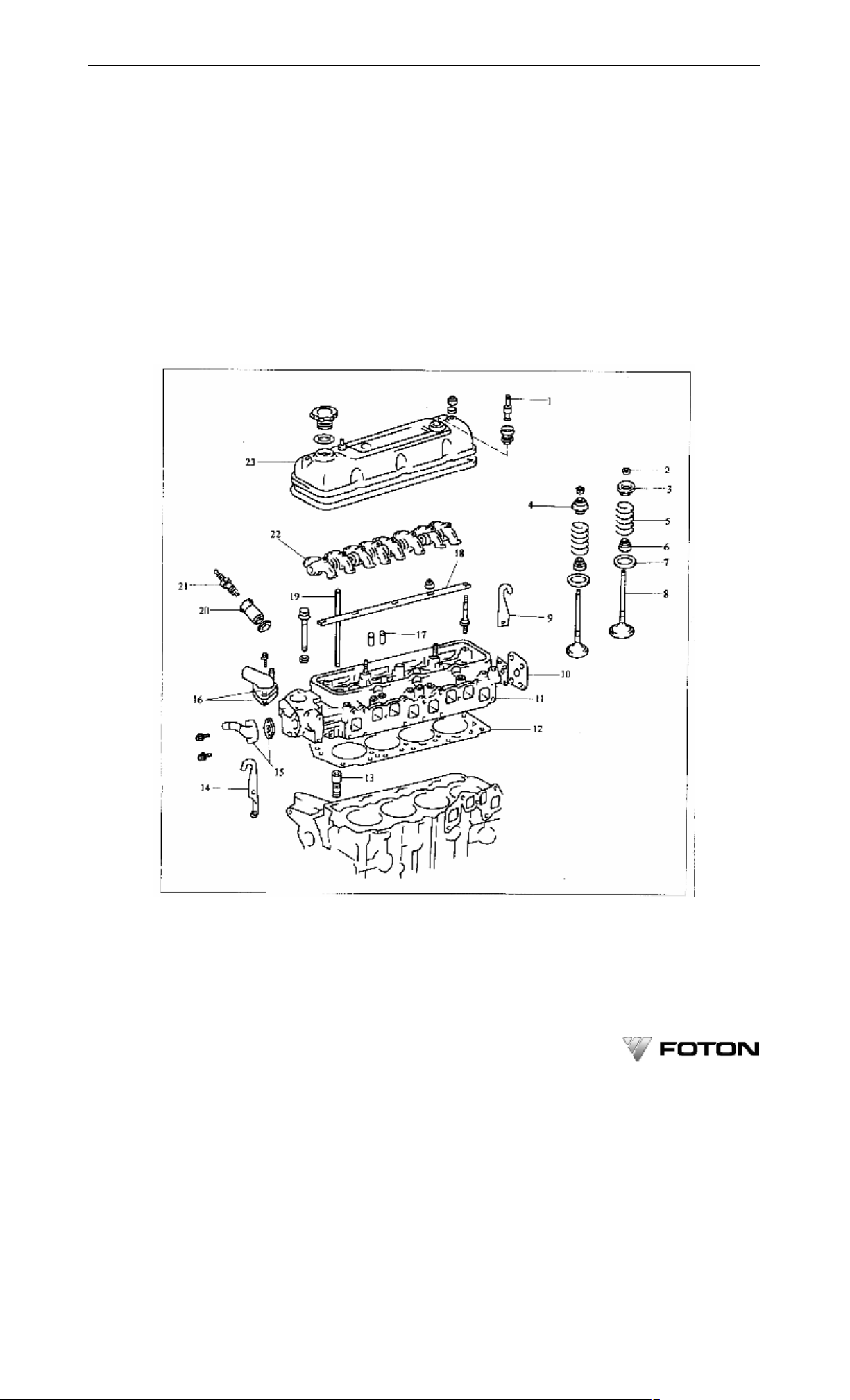
Chapter 3 Structure, Adjustment and Service of BJ491EQ1 Gasoline Engine
·63·
Chapter 3 Structure, Adjustment and Service of
BJ491EQ1 Gasoline Engine
Knowledge of structures of the gasoline engine parts, master of adjustment and maintenance essentials and
correct service, and maintenance to the gasoline engine can let the gasoline engine maintain its performance and
quality in long term. Following is a brief description of structures, adjustment and maintenance essentials for parts
of BJ491EQ1 multi point electronic fuel injection gasoline engine.
3.1 Cylinder head parts
The cylinder head parts of BJ491EQ1 multi-point electronic fuel injection gasoline engine is as shown in
Figure 3-1.
Figure 3-1 Cylinder Head Parts of BJ491EQ1 Multi Point Electronic Fuel Injection Gasoline Engine
1-PVC; 2-Valve keeper; 3-Intake valve spring top cap; 4-Exhaust valve spring top cap; 5-Valve spring; 6-Valve oil seal; 7- valve
spring bottom cap; 8-Valve; 9-Rear engine lug; 10-Rear cover of cylinder head; 11-Cylinder head; 12-Cylinder gasket; 13-Hydraulic
valve tappet; 14- Engine front lug; 15-Engine front water pipe assembly; 16-Exhaust pipe connector and gasket; 17-Valve guide;
18-Valve rocker arm shaft; 19-Valve push rod; 20-Spark plug cover; 21-Spark plug; 22-Valve rocker arm and spring; 23-Cylinder
head cover
Page 73

·64·
OPERATION AND MAINTENANCE MANUAL FOR FOTON VIEW SERIES LIGHT BUS
3.1.1 In order to prevent gas and water leakage from cylinder gasket, operator should check tightening torques
of cylinder head bolts with a torque wrench at every 500km and 2000km (for a new vehicle). The tightening
torques: 10 M12 bolts-- 93~105N·m; 3 M8 bolts--20~25N·m.
Tighen the bolts after the gasoline engine has cooled down. The tightening sequence is as shown in Figure
3-2.
Front
Figure 3-2 Tightening Sequence of Cylinder Head Bolts
● Note: A cylinder head bolt can only be used twice. If the bolt has been used twice, replace with a new one.
3.1.2 Follow the sequence indicated in figure 3-3 to disassemble the rocker arm shaft, unscrew the bolts and
nuts of rocker arm shaft in 2~3 times to avoid breaking off of rocker arm shaft and damage the bolts.
Follow a sequence that is reversed to these indicated in figure 3-3 to assemble the rocker arm shaft assembly,
tighten the bolts and nuts in 2~3 times. The final tightening torque is 25~32N·m.
After a new vehicle has driven 500km and 2000km, its bolts and nuts on rocker arm shaft should be tighened
as per above torque requirements.
Figure 3-3 Sequence for Disassembly of Rocker Arm Bolts
3.1.3 After the gasoline engine has cooled down, follow the sequence that is reversed to these indicated in
figure 3-2 to disassemble the cylinder head. Unscrew the bolts of cylinder head step by step in 3 times to avoid
distortion of cylinder head.
3.1.4 When to mount a cylinder gasket, apply high temperature resistant sealant on surfaces of its both sides so
as to ensure sealing performance. The gasket must be replace each time cylinder head has been dismantled (see
figure 3-4).
Page 74

Chapter 3 Structure, Adjustment and Service of BJ491EQ1 Gasoline Engine
New cylinder gasket
Front
·65·
Figure 3-4 Installation of Cylinder Gasket
3.1.5 After a cylinder head has been dismantled, clear gasket leftovers embedded on surfaces of cylinder head /
block with a cutter. Be careful not to scratch contact surface and prevent entry of gasket leftover into tappet hole,
water jacket hole and bolt hole (see Figure 3-5).
Figure 3-5 Clearing of Cylinder Head / Block
3.1.6 Check cylinder head for crack, and follow procedures indicated in figure 3-6 to measure warpages of
cylinder head base and sides where intake and exhaust manifold are installed.
Figure3-6 Cylinder Head warpage Mesurement
Maximum warpage:
Cylinder head base: 0.15mm;
Page 75

·66·
OPERATION AND MAINTENANCE MANUAL FOR FOTON VIEW SERIES LIGHT BUS
Manifold side: 0.10mm.
If its warpage exceeds the maximum value, cylinder head.should be replaced.
3.1.7 Check the fitting clearance between valve stem and valve guide hole (see Figure 3-7, Figure 3-8)
Diameter of valve guide inner hole: Φ8.010~Φ8.030mm;
Diameter of intake valve stem: Φ7.970~Φ7.985mm;
Diameter of exhaust valve stem: Φ7.965~Φ7.980mm.
Nominal fitting clearances:
Intake valve: 0.025~0.060mm;
Exhaust valve: 0.030~0.065mm;
Maximum fitting clearances:
Intake valve: 0.10mm;
Exhaust valve: 0.12mm.
If the clearance exceeds the maximum value, replace the valve and valve guide.
Figure 3-7 Check Diameter of Valve Guide
Figure 3-8 Check Diameter of Valve Stem
3.1.8 Check valve cone and plate for depression, groove and carbon deposit. If necessary, grind to correct the
valve cone angle (correct angle is 44.5º). The grinding extent should be as small as possible.(see Figure 3-9).
Nominal edge thickness of intake valve: 1.0~1.4mm;
Nominal edge thickness of exhaust valve: 1.3~1.7mm;
Minimum edge thickness of intake valve: 0.5mm;
Page 76

Chapter 3 Structure, Adjustment and Service of BJ491EQ1 Gasoline Engine
·67·
Minimum edge thickness of exhaust valve: 0.8mm.
Figure 3-9 Check and Grind Valve Cone
If the edge thickness of valve head is less than minimum value, valve should be replaced. (see Figure 3-10).
Nominal length of intake valve: 108.2mm;
Nominal length of exhaust valve: 108.5mm;
Minimum length of intake valve: 107.7;
Minimum length of exhaust valve: 108.0mm.
If total length of valve is less than the minimum value, valve should be replaced.
Edge thickness
Figure 3-10 Check the Edge Thickness of Valve Head
3.1.9 Check valve seat for wear, damage and carbon deposit. If necessary, grind and clean the valve seat. The
grinding extent should be as small as possible.
Coat a thin layer of Prussian blue (or white lead) on the valve cone, install the valve, gently press and turn
the valve to check its seating condition. If the valve cone along 360º is covered with blue, the valve must be
coaxial; otherwise replace the valve. If the valve along 360º is covered with blue, the valve guide and valve seat
must be concentric; otherwise grind the valve seat. The contact annulus should be at the middle of valve cone with
a width of 1.2~1.4mm (see figure 3-11).
Page 77

·68·
OPERATION AND MAINTENANCE MANUAL FOR FOTON VIEW SERIES LIGHT BUS
Width
Figure 3-11 Check of Wear Status of Valve Seat
If the contact annulus fails to comply with above requirements:
(1) If the contact annulus is on top of the valve cone, grind the valve seat with 30º and 45º mill (see figure 3-12).
Width
Figure 3-12 Grinding the Valve Seat with 30º and 45º mill
(2) If the contact annulus is at the bottom of the valve cone, grind the valve seat with 60º and 45º mill (see
figure 3-13).
(3) Grind the valve and valve seat with valve grinding compound to make them join closely without gas
leaking (see figure 3-14). After grinding, clean the valve, valve seat and inner hole of valve guide thoroughly.
Width
Figure 3-13 Grinding the Valve Seat with 45º and 60º Mill
Page 78

Chapter 3 Structure, Adjustment and Service of BJ491EQ1 Gasoline Engine
·69·
Figure 3-14 Grinding of Valve and Valve Seat
3.1.10 Measure the free length of valve spring with a caliper, the reading should be 47mm ± 0.5mm; measure
perpendicularity of valve spring with a surface plate and a square, the reading should be less than or equal to 2mm.
If free length or perpendicularity of valve spring exceeds the specified limit, replace the valve spring.
Measure the elastic force of valve spring at nominal installation length 40.6mm with a spring tester, the
reading should be 292~336N. If the elastic force of valve spring at nominal installation length does not comply
with the specified value, replace the valve spring (see figure 3-15).
Figure 3-15 Measue elastic force of valve spring
3.1.11 Check valve rocker arm and rocker arm shaft:
(1) Check for wear on contact surface between valve rocker arm and valve, if necessary, polish this surface
or replace the rocker arm.
(2) Push and turn the rocker arm by hand along the direction shown in figure 3-16, if a relative movement
margin is felt, disassemble and check the fitting clearance between the valve rocker arm and the rocker arm shaft.
Page 79

·70·
Up
OPERATION AND MAINTENANCE MANUAL FOR FOTON VIEW SERIES LIGHT BUS
Figure 3-16 Check Valve Rocker Arm and Rocker Arm Shaft
Inner diameter of valve rocker arm: Φ18.500~Φ18.515mm;
Diameter of rocker arm shaft: Φ18.474~Φ18.487mm;
Nominal fitting clearances: 0.02~0.051 mm;
Maximum fitting clearance: 0.08mm.
If the clearance exceeds the maximum value, replace the valve rocker arm and rocker arm shaft.
(3) Make sure the direction of rear end boss (valve rocker arm shaft) is correct, and follow figure 3-17 to
assemble valve rocker arm and spring. Use special tools to install and clamp during assembly.
Special tool
Forward
Heave
With heave
Figure 3-17 Installation of Valve Rocker Arm
3.1.12 Check push rod
(1) Follow figure 3-18 to check run-out at middle of push rod. The maximum value is 0.30mm. If the value
exceeds the maximum, replace the push rod.
(2) Check oil passage hole of push rod for clogging. If clogging is present, use compressed air to clear up.
Page 80

Chapter 3 Structure, Adjustment and Service of BJ491EQ1 Gasoline Engine
Figure 3-18 Check Run-out at Middle of Push Rod
·71·
3.1.13 Use special tools (figure 3-19) to disassemble and assemble the valve. The valve spring end with white
paint faces down at mounting.
Special tool
Figure 3-19 Disassembly and Installation of Valve Spring
3.2 Cylinder block parts
See Figure 3-20 for cylinder block parts and crank-connecting rod mechanism parts in BJ491EQ1 multi point
electronic fuel injection gasoline engine.
Page 81

·72·
OPERATION AND MAINTENANCE MANUAL FOR FOTON VIEW SERIES LIGHT BUS
Figure 3-20 Cylinder Block Parts and Crank-connecting Rod Mechanism Parts -- BJ491EQ1 Multi Point
Electronic Fuel Injection Gasoline Engine
1-Piston ring; 2-Piston; 3-Connecting rod and connecting rod cap; 4-Connecting rod bearing sleeve; 5-Rear oil seal gasket;
6-Rear oil seal cover; 7-Drain switch; 8-Main bearing shell of crank; 9-Crankshaft thrust plate; 10-Main bearing cap; 11-Engine oil
strainer; 12-Oil pan assembly; 13-Engine oil pump; 14-Crank; 15-Sprocket chamber gasket; 16-Sprocket chamber cover gasket;
17-Crank pulley; 18-Sprocket chamber cover; 19-Timing chain and sprocket; 20-Sprocket chamber casing
Page 82

Chapter 3 Structure, Adjustment and Service of BJ491EQ1 Gasoline Engine
No. 3 bearing cap
No. 1,2,4 and 5 bearing caps
·73·
3.2.1 Check axial clearance between big end of connecting rod and end surface of crank-connecting rod journal
with a feeler or a dial indicator. Nominal clearance: 0.160~0.312mm; maximum axial clearance: 0.35mm. If the
clearance exceeds the maximum value, replace the connecting rod (see Figure 3-21).
Figure 3-21 Check End Clearance of Connecting Rod Big End
3.2.2 Check end clearance of crank with a dial indicator. Nominal clearance: 0.02~0.22mm, maximum end
clearance: 0.35mm. If the clearance exceeds the maximum value, replace with a new set of thrust plates. Nominal
thickness of thrust plate: 2.440~2.490mm.
3.2.3 The main bearing caps are not interchangeable, and their directions (front and rear) must be correct. In
order to prevent misplacement or adverse installation, the main bearing cap is marked with sequence number
and cast a “forward” arrow (see Figure 3-22).
Forward Forward
Figure 3-22 Marks on Main Bearing Cap
Figure 3-23 Assemble a Thrust Plate
Page 83

·74·
OPERATION AND MAINTENANCE MANUAL FOR FOTON VIEW SERIES LIGHT BUS
3.2.4 Thrust plates are installed respectively on both sides of 3rd main bearing seat / cap of cylinder block.
●Note:
(1) When to install a thrust plate, its side with oil groove should be outward. Never install it in adverse
direction (see Figure 3-23).
(2) There are oil grooves and oil holes on the main bearing cover that is installed on cylinder block. The
upper and lower covers can not be installed adversely.
3.2.5 Check cylinder block for crack and damage, and follow Figure 3-24 to check warpage on top deck of
cylinder block with a fine ruler and a feeler (the value should be less than 0.05mm). If the warpage exceeds the
specified limit, use surface grinder to grind the top deck of the cylinder block. Or replace the unserviceable
cylinder block.
Figure 3-24 Check Warpage on Top deck of Cylinder Block
3.2.6 Measure inner diameter of each cylinder bore. Measuring position and direction see Figure 3-25. Nominal
diameter of cylinder bore is Φ91.00~Φ91.03mm. See Table 3-1 for diameters of cylinder bore groups..
Table 3-1 Diameters of Cylinder Bore Groups
First group Φ91.00mm≤D<Φ91.01mm
Second group Φ91.01mm≤D<Φ91.02mm
Third group Φ91.02mm≤D<Φ91.03mm
Lateral
Front
Longitudinal
Middle
Figure 3-25 Measurement of Cylinder Bore Diameter
Maximum cylinder bore diameter: Φ91.23mm.
If diameter exceeds the maximum value, re-bore the four cylinders.
Page 84

Chapter 3 Structure, Adjustment and Service of BJ491EQ1 Gasoline Engine
·75·
3.2.7 If deep longitudinal score or burn-out is present on cylinder wall, re-bore the four cylinders. The increased
diameter of cylinder bore during repairing (+0.50mm) is Φ91.50~Φ91.53mm. After repair, the wear limit of
cylinder bore is Φ91.73mm.If the value exceeds this limit, replace the cylinder block.
3.2.8 Diameter of gasoline engine piston falls into three groups (see Table 3-2) , each matches the cylinder bore
in the same group. The grouping mark is on top of piston.
Table 3-2 Piston Diameter Group
First group Φ90.938mm≤D<Φ90.948mm
Second group Φ90.948mm≤D<Φ90.958mm
Third group Φ90.958mm≤D<Φ90.968mm
Measuring position for piston diameter: at skirt section, 24mm from top along the direction vertical to piston
pin (see Figure 3-26).
The increased piston diameter for repair is Φ91.438~Φ91.468mm.
The fitting clearance between piston and cylinder is 0.052~0.072mm. Follow the following formula to
calculate the required re-boring dimension.
Cylinder re-boring dimension = piston diameter + cylinder fitting clearance with piston – boring margin
The boring margin should be less than 0.02mm, because excessive boring may destroy finely machined
roundness and cylindricity.
Figure 3-26 Measurement of Piston Diameter
3.2.9 The main bearing hole dimensions fall into three groups. The grouping numbers for first to fifth holes are
marked on rear end of bottom plane of cylinder block. The main bearing shells also fall into three groups. During
assembly, select the main bearing shell with the same grouping number as main bearing hole, and install it into
corresponding main bearing hole (see Figure 3-27).
Check for fitting clearance between crankshaft main journal and main bearing shell. The nominal clearance is
0.020~0.051mm, the maximum value is 0.1mm. If the clearance exceeds the maximum, replace the main bearing
shell, or replace the crankshaft if necessary.
Page 85

·76·
OPERATION AND MAINTENANCE MANUAL FOR FOTON VIEW SERIES LIGHT BUS
1, 2 or 3
Front
Figure 3-27 Matching of Main Bearing shell
3.2.10 Follow Figure 3-28 to check run-out of main journal at middle of crankshaft (the maximum run-out is
0.06mm). If the run-out exceeds the maximum value, replace the crankshaft.
Nominal diameter of crankshaft main journal is Φ57.985~Φ58.000mm; nominal diameter of connecting rod
journal is Φ47.985~Φ48.000mm; cylindricity limit of main journal and connecting rod journal is 0.020mm.
Replace the crankshaft if it is out of these range.
Figure 3-28 Check Crankshaft
3.3 Crank-connecting rod mechanism
The crank-connecting rod mechanism of BJ491EQ1multi point electronic fuel injection gasoline engine is as
shown in Figure 3-20.
3.3.1 Check fitting clearance between crank-connecting rod journal and connecting rod shell. The nominal
clearance is 0.020~0.051mm, and the maximum value is 0.100mm. If the fitting clearance exceeds this maximum
value, replace the connecting rod shell or replace the crankshaft if necessary,
3.3.2 Both connecting rod big end holes and connecting rod bearing shells fall into three groups with marks as 6,
7, 8. Assembly should be made within same group.
Mating numbers are marked on sides of connecting rod body and connecting rod cap. Interchanged assembly
is prohibited. The semicircle heaves on connecting rod body and connecting rod cap should be on the same side
with that of piston that has a depression mark on top. They should all face engine front (see Figure 3-29).
Page 86

Chapter 3 Structure, Adjustment and Service of BJ491EQ1 Gasoline Engine
Depression
Semicircle heave part
·77·
Figure 3-29 Semicircle Heaves on Connecting Rod Body and Connecting
Rod Cap and Depression Mark on Top of Piston
3.3.3 Check bending extent (see Figure 3-30) and distortion (see Figure 3-31) of connecting rod with a
connecting rod corrector. Maximum bending extent: 0.05mm for every 100mm; maximum distortion: 0.05mm for
every 100mm. If bending extent or distortion exceeds the maximum value, replace the connecting rod.
Figure 3-30 Check Bending Extent of Connecting Rod with a Connecting Rod Corrector
Figure 3-31 Check Distortion of Connecting Rod
●Note: When to replace the connecting rod, its cover and bearing shell should be replaced at the same time.
3.3.4 Check piston and piston ring groove for wear. Replace piston if necessary.
●Note: If piston has to be replaced, the ring on it should also be replaced.
The clearance between piston and piston ring (ring groove clearance) is 0.03~0.07mm. If the ring groove
clearance does not comply with the specified value, replace the piston.
Install piston ring into cylinder bore, use piston to press it to the position where is 110mm from top of
Page 87

·78·
OPERATION AND MAINTENANCE MANUAL FOR FOTON VIEW SERIES LIGHT BUS
cylinder block, and then measure ring opening clearance (end clearance) with a feeler. Nominal end clearances:
first ring 0.27~0.39mm; second ring 0.40~0.55mm; oil ring: 0.20~0.70mm. Maximum end clearance: first ring:
1.11mm; second ring: 1.07mm; oil ring: 1.10mm (see Figure 3-32).
Figure 3-32 Check Piston Ring Opening Clearance
3.3.5 Use special tools to disassemble and assemble piston and connecting rod assemblies. The usage for
special disassembling tools are as shown in Figure 3-33. The usage for special assembling tools are as shown in
Figure 3-34.
Figure 3-33 Special Tools to Dismantle Piston and Connecting Rod Assemblies
1-Special tools; 2-Piston pin
Figure 3-34 Special Tools to assemble Piston and Connecting Rod Assemblies
1-Special tools; 2-Piston pin
3.3.6 After three piston rings are installed onto ring grooves, their opening positions should be interleaving as
shown in Figure 3-35 with marks on first ring and second ring facing upwards.
Page 88

Chapter 3 Structure, Adjustment and Service of BJ491EQ1 Gasoline Engine
First ring and oil ring
·79·
Second ring
Front
Oil ring lower blade
Oil ring upper blade
bushing spring
Figure 3-35 Opening Positions of Piston Rings
3.3.7 Check for fitting clearance between bearing hole and journal of camshaft. Inner diameters of bearing
holes (counting from front end) are as follows:
First hole: Φ46.500~Φ46.570mm;
Second hole: Φ46.250~Φ46.320mm;
Third hole: Φ46.000~Φ46,070mm;
Fourth hole: Φ45.750~Φ45.820mm;
Fifth hole: Φ45.500~Φ45.570mm;
Nominal fitting clearances: 0.025~0.111mm;
Maximum fitting clearance: 0.140mm.
If the clearance exceeds the maximum value, replace the camshaft bearing, and replace the camshaft when
necessary.
3.3.8 Measure diameter of hydraulic tappet hole. The value should be Φ21.417~Φ21.443 mm. Nominal fitting
clearance between tappet hole and tappet is 0.017~0.056mm, the maximum value is 0.100mm. If the clearance
exceeds the maximum, replace the tappet.
3.4 Valve Train
3.4.1 Using a wire, follow the procedures in figure 3-36 to take out the valve tappet.
Figure 3-36 Take out Valve Tappet
● Note: Place orderly the valve tappets with heads up for easy re-assembly.
3.4.2 Using a spring scales to pull the timing chain with a force of 98N (Figure 3-37). Measure the clearance
“△” between chain tensioner plug and support, the value should not exceed 13.5mm. Otherwise replace with new
timing chain and sprocket.
Page 89

·80·
OPERATION AND MAINTENANCE MANUAL FOR FOTON VIEW SERIES LIGHT BUS
Figure 3-37 Check timing chain slackness
3.4.3 Measure journal run-out at middle of camshaft (Figure 3-38), the maximum value should be 0.06mm.
Otherwise replace the camshaft.
Figure 3-38 Measure Journal Run-out at Middle of Camshaft
Check cam height, the nominal heights of cams should be as follows:
Intake cam: 38.620~38.720mm;
Exhaust cam: 38.629~38.729mm;
Minimum cam height:
Intake cam: 38.26mm;
Exhaust cam: 38.27mm;
If cam height is less than the minimum value, replace the camshaft.
Check camshaft journal, the nominal diameters are (count from front end):
First journal: Φ46, 459~Φ46.475mm;
Second journal: Φ46.209~Φ46.225mm;
Third journal: Φ45.959~Φ45.975mm;
Fourth journal: Φ45.709~Φ45.725mm;
Fifth journal: Φ45.459~Φ45.475mm.
If journal dimension of is not within the specified range, follow the procedures indicated in 3.3.7 of this
chapter to check the fitting clearance between camshaft bearing hole and journal.
3.4.4 Install the thrust plate and camshaft sprocket onto camshaft, tighten the fixing bolts of camshaft sprocket
with a 90N.m tightening torque, and then measure axial clearance between thrust plate and first journal thrust
surface with a feeler (see Figure 3-39). The nominal axial clearance is 0.07~0.22mm. The maximum axial
Page 90

Chapter 3 Structure, Adjustment and Service of BJ491EQ1 Gasoline Engine
·81·
clearance is 0.30mm. If the clearance exceeds the maximum value, replace the camshaft bearing. Or replace the
camshaft if necessary.
Figure 3-39 Measure Camshaft Axial Clearance
3.4.5 Check length of timing chain. Using a spring scales( Figure 3-40) to pull (49N) the chain.The maximum
chain length is 291.4mm. Select 3~4 measurement points at random to measure. If chain length exceeds the
maximum value, chain should be replaced.
3.4.6 Using a caliper (Figure 3-41) to measure diameters of crankshaft timing sprocket and camshaft timing
sprocket ( with chain). Minimum diameters are:
Crankshaft sprocket of: Φ59mm;
Camshaft sprocket: Φ114mm;
If sprocket diameters are less than the minimum value, replace the chain and two sprockets.
Figure 3-40 Check Timing Chain Length
Figure 3-41 Measure Diameters of Crankshaft Timing Sprocket and Camshaft
Timing Sprocket (with Chain)
Page 91

·82·
OPERATION AND MAINTENANCE MANUAL FOR FOTON VIEW SERIES LIGHT BUS
3.4.7 Use a caliper to check the thickness of rubber damper. The damper is on the head of chain tensioner plug
(see Figure 3-42). The nominal thickness is 15.0mm, and minimum thickness is 12.5mm.
Figure 3-42 Check the Thickness of Chain Tensioner Rubber Damper
If the thickness is less than the minimum value, replace the plug or chain tensioner assembly. When to
replace or re-instal the plug, operator should first apply a layer of engine oil onto chain tensioner body hole and
plug’s sliding surface.
3.4.8 Check thickness of rubber layer on damper. The nominal thickness is 6.6mm and minimum thickness is
5mm. If the thickness is less than minimum value, replace the damper.
3.4.9 Check outer diameter of valve tappet. The value should be 21.387~21.404mm. Otherwise check fitting
clearance between tappet hole of cylinder block and valve tappet by following procedures in 3.3.8 of this chapter .
3.4.10 Before installing valve tappet onto gasoline engine, discharge the air its inner chamber first and recheck
to ensure air is discharged completely. The methods are as follows (see Figure 3-43):
Figure 3-43 Discharge air from tappet
1-Push rod support; 2-Plunger
Dip the plunger into an engine oil pan, depress push several times to discharge air from tappet inner chamber.
Then fill the chamber with engine oil. Depress push rod again, if push rod is very hard or even fail to move the
plunger, this indicates tappet is in good condition; if plunger is easy to be pressed down, that indicates the tappet is
leaking and should be replaced.
● Note: Tappet body and plunger are precise coupler, which are not allowed to disassemble or interchange at
will. Be sure to use clean oil to perform these procedures.
3.4.11 Leak down test for valve tappet: if possible, use a leak down tester to check tappet leak down(Figure 3-44).
The test oil is industrial alcohol or special test oil. Apply a pressure (196N) on the plunger, and measure the time
required for another 1mm plunger leak down after the plunger has dropped by 2mm (the value should be 7~50s).
Page 92

Chapter 3 Structure, Adjustment and Service of BJ491EQ1 Gasoline Engine
Mark
(testing ambient temperature is 20℃).
Figure 3-44 Valve Tappet Leak down test
3.4.12 Installation tips for timing sprocket and timing chain:
(1) When to install camshaft thrust plate, its side with two depressions should direct to engine front;
(2) Rotate the crankshaft to move sprocket key to the top, let the key on camshaft top and align with the
depression mark on thrust plate (see Figure 3-45).
·83·
Figure 3-45 Installation of Timing Sprocket and Timing Chain
1-Aligning key of sprocket on camshaft; 2-Aligning key of sprocket on crankshaft
(3) Put the timing chain onto the timing sprockets on camshaft and on crankshaft, and let the two bright
white nodes on the chain respectively align with the depressions on two sprockets.
(4) Let key notches on two sprockets respectively align with the aligning keys on crankshaft and camshaft,
and then install the two sprockets and timing chains evenly and simultaneously (see Figure 3-46).
Page 93

·84·
OPERATION AND MAINTENANCE MANUAL FOR FOTON VIEW SERIES LIGHT BUS
Figure 3-46 Installation of Sprocket and Chain
3.5 Lubrication system
3.5.1 Check quality of engine oil
Check engine oil in lubrication system for deterioration, moisture, color change or thinning. Change any
inferior oil. Inferior oil may affect the performance and service life of a gasoline engine.
● Note:
(1) Dispose properly changed oil to protect environment.
(2) The engine oil used in lubrication system should comply with the specification in this manual (see
3.2.2)
3.5.1 Check volume of engine oil
Check the volume of engine oil in oil pan with the dipstick. The oil level should be within upper and lower
scales of the dipstick. If the oil level is below the lower mark (L), check for leakage and fill with engine oil till the
oil level reaches upper scale (F) (see Figure 3-47).
Figure 3-47 Check Oil Volume in Oil Pan with the Dipstick
● Note: The oil level could not be higher than the upper scale (F) on dipstick. Otherwise, oil consumption
would become high and the service life of three-way catalytic converter would be shortened as well.
Page 94

Chapter 3 Structure, Adjustment and Service of BJ491EQ1 Gasoline Engine
3.5.3 Replace engine oil filter
Use special wrench to remove the oil filter. Check and clean the installation surface on filter seat. Coat clean
engine oil on new oil filter gasket (see Figure 3-48).
As shown in Figure 3-49, spin on the new filter onto the filter seat by hand until some resistance is felt, and
then use a special wrench to rotate for 3/4 turn.
● Note: Engine oil filter is one-time service part, which can not be used repeatedly. Dispose the used engine
oil and engine oil filter properly to protect environment.
3.5.4 Check engine oil pump
The engine oil pump is installed on lower front right side of cylinder block and is driven by a impeller.
·85·
Figure 3-48 Replace Engine Oil Filter
Special tool
Figure 3-49 Installation of Engine Oil Filter
(1) Dip the oil strainer into engine oil, rotate the pump shaft clockwise. Engine oil should flow out from oil
outlet of oil pump.
(2) Block the oil pump outlet with thumb and rotate the pump shaft with a slotted point screwdriver. It
should be hard to be rotated.
3.6 Cooling system
3.6.1 Check coolant volume in reservoir
The level of coolant in reservoir should be within upper and lower scales. Add coolant if necessary.
3.6.2 Check coolant quality
(1) Check coolant for cleanness. Change any dirty coolant.
Page 95

·86·
OPERATION AND MAINTENANCE MANUAL FOR FOTON VIEW SERIES LIGHT BUS
(2) Check if rust is present around radiator cap and radiator opening.
(3) Check coolant for smear.
3.6.3 Check cooling system
(1) Check cooling system for leakage.
(2) Check radiator and hose for damage and distortion.
(3) Check hose clamps for looseness.
3.6.4 Check fan belt
(1) Check fan belt for crack, extending, deterioration or serious wear. Replace if necessary.
(2) As shown in Figure 3-50, make sure the fan belt engages correctly into pulley.
Correct Incorrect
Incorrect
Figure 3-50 Check Engagement of Fan Belt into Pulley
(3) Check and adjust fan belt tension (see Figure 3-51): Use a force of 98N to press the belt at middle spot
between alternator and water pump. If the deflection is 7~8mm (for a new belt 5-7mm), belt tension is nominal;
otherwise adjust it.
Figure 3-51 Check and Adjust Fan Belt Tension
(4) In cold region, replace with low temperature proof belt in winter.
3.6.5 Check thermostat
Dip the thermostat into water under heating. Gradually to heat up water while checking its opening
temperature and valve stroke (see Figure 3-52).
Page 96

Chapter 3 Structure, Adjustment and Service of BJ491EQ1 Gasoline Engine
Figure 3-52 Check Thermostat
Opening temperature of the valve: 76℃;
Stroke of the valve: more than 8mm at 88℃.
If the opening temperature and stroke do not comply with specification, replace the thermostat.
The oscillating valve on the thermostat should be turn to upper left position during thermostat installation
(see Figure 3-53).
·87·
Oscillating valve
Figure 3-53 Installation of Thermostat
3.6.6 Check water pump
Check water pump and timing sprocket chamber body for crack; check fitting surface for damages, and check
water pump bearing for free rotation and noise (see Figure 3-54).
● Note: Observe if there is coolant leaking trace from overflow opening.
3.6.7 Check silicon oil fan clutch
Check silicon oil fan clutch (excl. rigid coupling fan) for damage and silicon oil leak. If any, replace the
silicon oil clutch. See Figure 3-55.
Page 97

·88·
OPERATION AND MAINTENANCE MANUAL FOR FOTON VIEW SERIES LIGHT BUS
Figure 3-54 Check Water Pump
Figure 3-55 Check Silicon Oil Fan Clutch
3.7 Starting system
See figure 3-56 for the starting system of BJ491EQ1 multi point electronic fuel injection gasoline engine.
Ignition switch
Fuse
Terminal 30
Battery
Figure 3-56 Starting System of Gasoline Engine
Terminal 50
Starter
Page 98

Chapter 3 Structure, Adjustment and Service of BJ491EQ1 Gasoline Engine
·89·
3.7.1 Attraction test for starter
Disconnect excitation coil from C terminal (see Figure 3-57); connect the battery to solenoid, the pinion should
extend out at the moment. If the pinion does not act, replace the solenoid assembly.
Terminal C
Terminal 50
Figure 3-57 Attraction Test for Starter
3.7.2 Maintenance test for starter
As per procedures, when the pinion is in extended position, disconnect negative lead and the pinion should
still be in extended out position. If the pinion retracts, replace solenoid assembly (see Figure 3-58).
Figure 3-58 Maintenance Test for Starter
3.7.3 Check retraction of starter pinion
As shown in Figure 3-59, disconnect negative lead from the solenoid switch body, and the pinion should
retract inwards. If the pinion does not retract, replace the solenoid switch assembly.
Page 99

·90·
OPERATION AND MAINTENANCE MANUAL FOR FOTON VIEW SERIES LIGHT BUS
Figure 3-59 Check retraction of Starter Pinion
3.7.4 No-load performance test for starter
As shown in Figure 3-60, connect battery and an vlotage meter, and the pinion should extend out. Check if
the starter rotates freely and stably. Check the current, the value should be less than 90A.
Terminal 50
Terminal 30
Figure 3-60 No-Load Performance Test for Starter
3.8 Charging system
Model 65A/90A alternator with regulator is used in BJ491EQ1 engine’s charging system. Its connection is as
shown in Figure 3-61.
3.8.1 Check alternator connection for any abnormal noise during engine running. Dismantle to check if any.
● Warning: Never connect or disconnect wiring during engine running to avoid accident.
3.8.2 Check charging indicator lamp circuit. Start the engine and shut it down after it has warmed up. Turn off
all electrical accessories. Turn the ignition switch to “ON”, the charging indicator lamp should lit then.
Page 100

Chapter 3 Structure, Adjustment and Service of BJ491EQ1 Gasoline Engine
Soft
Charging
connection
of battery
indicator lamp
Fuse (5A)
Fuse box
Figure 3-61 Charging System Circuit
The charging indicator lamp should extinguis after engine has started. Otherwise check circuit of charging
indicator lamp.
3.9 Crankcase ventilation
·91·
BJ491EQ1 multi point electronic fuel injection gasoline engine is equipped with positive crankcase
ventilation device, which sucks the exhaust gas leaking into the crankcase to intake manifold and then into the
combustion chamber (via vent valve) to burn again. This design tends to protect oil from contaminatded by fuel,
and protect component surface from corrosion due to anhydride formed from exhaust gas and water vapor.
Therefore, never remove the crankcase ventilation device.
The crankcase ventilation system is mainly composed of the positive crankcase ventilation device (PCV) that
is installed on the cylinder head cover, a vent pipe that connects vent valve to intake pipe, and a short pipe that
connects valve cover to air filter pipe.
● Note: During operation, be sure to prevent the vent valve from being clogged. No damage and gas leak on
connecting hose are allowed.
3.10 Clutch
BJ491EQ1 multi point electronic fuel injection gasoline engine adopts diaphragm spring clutch.
3.10.1 Check driven plate of clutch for wear or damage. Measure the depth of rivet head in friction plate. The
depth should not be less than 0.3mm, otherwise replace the driven plate (see Figure 3-62).
If necessary, replace plate and cover assembly of a clutch.
3.10.2 Check for run-out tolerance on the edge of driven plate (see Figure 3-63). The maximum run-out
tolerance is 0.8mm. If it exceeds this value, replace the driven plate.
3.10.3 Check diaphragm spring for wear. As shown in Figure 3-64, measure depth and width of wear on
diaphragm spring with a caliper. The maximum value: depth 0.6mm, width 5.0mm.
 Loading...