

FortiWeb 1000E
QuickStart Guide

Register for Support
Register your Fortinet product to receive:
• Technical Support
• New product features
• Protection from new threats
Vous devez enregistrer le produit pour recevoir:
• Support technique
• Nouvelles fonctionnalitées du produit
• Protection contre de nouvelles menaces
La reistrazione ti permette di usufruire di:
• Supporto Tecnico
• Nuove funzionalita
• Proteezione dalle ultime minaccce
Debe registrar el producto para recibir:
• Apoyo técnico
• Nuevas funcionalidades del producto
• Protección contra ataques
登録のお願い
本日、フォーティネット製品の登録をしてください。
登録すると次のメリットがあります。
テクニカルサポート • 新機能の追加 • 新しい脅威への防御
QuickStart Guide
September 30, 2018
3rd Edition
Copyright© 2017–2018 Fortinet, Inc. All rights reserved. Fortinet®, FortiGate®,
FortiCare® and FortiGuard®, and certain other marks are registered trademarks
of Fortinet, Inc., in the U.S. and other jurisdictions, and other Fortinet names
herein may also be registered and/or common law trademarks of Fortinet.
All other product or company names may be trademarks of their respective
owners. Performance and other metrics contained herein were attained in
internal lab tests under ideal conditions, and actual performance and other
results may vary. Network variables, dierent network environments and other
conditions may aect performance results. Nothing herein represents any
binding commitment by Fortinet, and Fortinet disclaims all warranties, whether
express or implied, except to the extent Fortinet enters a binding written
contract, signed by Fortinet’s General Counsel, with a purchaser that expressly
warrants that the identied product will perform according to certain expresslyidentied performance metrics and, in such event, only the specic performance
metrics expressly identied in such binding written contract shall be binding on
Fortinet. For absolute clarity, any such warranty will be limited to performance
in the same ideal conditions as in Fortinet’s internal lab tests. In no event
does Fortinet make any commitment related to future deliverables, features or
development, and circumstances may change such that any forward-looking
statements herein are not accurate. Fortinet disclaims in full any covenants,
representations, and guarantees pursuant hereto, whether express or implied.
Fortinet reserves the right to change, modify, transfer, or otherwise revise this
publication without notice, and the most current version of the publication shall
be applicable.
请马上注册
您的飞塔产品
您在注册以后才能得到技术支持、新产品特点信息、最新威胁防护
https://support.fortinet.com
Toll free: 1 866 648 4638
Phone: 1 408 486 7899
Fax: 1 408 235 7737
Email: register@fortinet.com
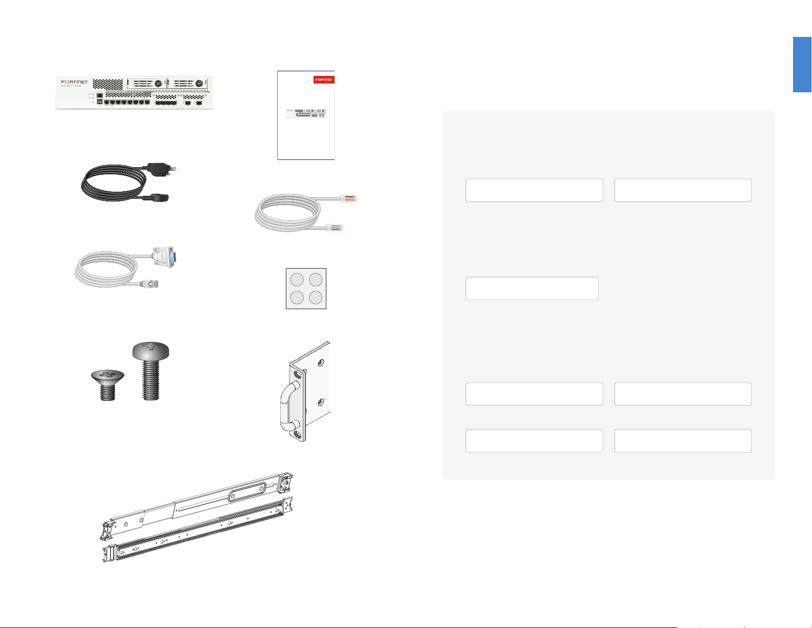
Box Includes Before You Begin
Write down details that you may need from your network administrator or ISP.
FortiWeb 1000E
2 Power cables
Console cable
4 M4 screws for rack mount ear brackets
2 M5 screws for rack mount screws
FortiWeb 1000E
QuickStart Guide
QuickStart Guide
Ethernet cable
4 Rubber feet
DSL PPPoE
Username
Password
Cable Modem DHCP
It is normal to not require a hostname but your ISP may require it.
Hostname
T1/E1, Static broadband, Cable, or DSL with a static
IP
IP Address
Default Gateway
Subnet Mask
Primary/Secondary DNS
2 Rack mount ear brackets
2 Sliding rails
2
3
1
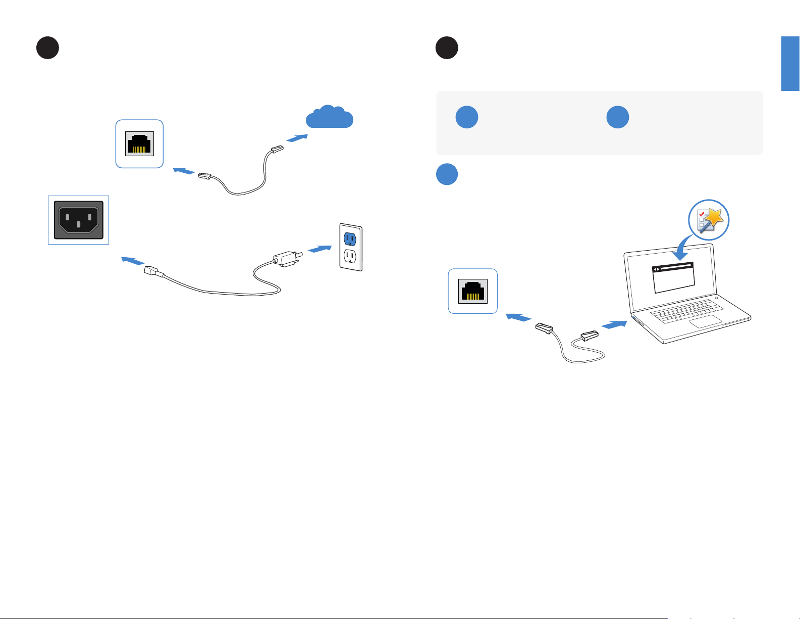
Basic Connections FortiWeb Setup Options
2
Internet
Ethernet Port
Power Connection
Connect your device to a power outlet and an Internet connection with an Ethernet port
(ports 1-12). This is usually a modem, but could also be another device on your network.
Web Browser
A
With Ethernet cable (p.5)
A
Web Browser with Ethernet cable
MGMT1
Terminal Emulation
B
With console cable (p.6 )
https://
Web-based Manager
1. Use the Ethernet cable to connect MGMT port of the FortiWeb unit to the
management computer.
2. Congure the management computer to match the FortiWeb unit’s default MGMT
subnet. For example:
IP address: 192.168.1.2
Netmask: 255.255.255.0
3. Visit 192.168.1.99 in your web browser.
4. Login using username “admin” and no password.
5. Congure your device and save your settings.
6. Register your device from the dashboard page.
544 5

B
Terminal Emulation with Console
Cable
3
General Installation
The FortiWeb unit can be mounted in any standard 19 inch rack unit with the provided
rail mount kit.
Serial Port
Console Port
To Connect to the CLI
1. Connect the FortiWeb unit console port to the management computer using the
provided console cable.
2. Start a terminal emulation program on the management computer. Select the COM
port and use the following settings:
Baud Rate: 9600
Data bits: 8
Parity: None
Stop bits: 1
Flow Control: None
3. Press Enter on your keyboard to connect to the CLI.
4. Login using username “admin” and no password. You can now proceed with
conguring your FortiWeb unit.
Please read the “Cautions and Warnings” on page 20 prior to installing your device.
To install the FortiWeb unit into a rack:
1. Ensure that the FortiWeb unit is placed on a stable surface prior to rack-mount
installation.
2. Assemble the rails and install the system in the rack following the safety instructions
and the rack installation instructions in Rail Installation (p. 8).
3. Verify that the spacing around the FortiWeb unit conforms to requirements and that
the unit is level.
4. Connect the provided power cables to the system.
5. Plug the other end of the power cables into separate power sources, such as
uninterruptible power supplies (UPS) or power distribution units (PDU).
6. Insert one end of the provided Ethernet cable into one of the Ethernet ports on the
FortiWeb unit. Insert the other end to a router or switch that is connected to the
Internet.
7. Press the power button on the system to turn on the device.
Do not place heavy objects on the unit.
Get started by typing “?” for a list of available commands.
Begin typing a command and type “?” for a list of available ways to complete.
For example “cong ?” shows the lowest level of conguration options.
For a detailed guide, visit http://docs.fortinet.com/fortiweb/reference.
76

4
Rail Installation
To install the FortiWeb unit using the rail mount kit:
1. To remove the chassis (inner) member, pull the slide open, and then press the trigger
down as shown on the drawing, and pull the chassis (inner) member out.
Press the trigger
down to release
Pull chassis (inner)
member out
Release safety lock
before mounting
Push the safety lock forward to secure
4. To mount the chassis into the cabinet, rst ensure that the ball retainer is in the fully
open position. Then, insert the chassis (inner) member into the cabinet member.
When you push the chassis back into the cabinet, press the trigger down to release
the slide from the locked position.
2. Use the standos to mount the chassis (inner) member to the chassis.
3. To attach the cabinet (outer) member to the rail, rst ensure that the safety lock is in
the unlocked position. Then, insert the stag into the upper and lower square holes on
the EIA rail from the back of the rail.
Finally, push the safety lock forward to secure the bracket.
88 9
Retainer is in fully open position
Press trigger down to unlock slides

Caution: SFP
SFP Cage Sockets
Transmit Optical Bore
transceivers are
static sensitive
devices. Use
an ESD wrist
strap or similar
grounding device
when handling
transceivers.
Do not install
or remove SFP
transceivers while
ber-optic cables
are still attached.
This can cause
damage to the
cables, cable
connectors,
and the optical
interfaces. It may
also prevent the
transceiver from
latching correctly
into the socket
connector.
Note: Installing
and removing
SFP transceivers
can shorten their
useful life. Do not
install or remove
transceivers more
than is necessary.
SFP Transceivers
Receive Optical Bore
To install the SFP transceivers
1. Ensure that you are properly grounded.
2. Remove the caps from the SFP cage sockets on the
front panel of the unit.
3. Position the SFP transceiver in front of the cage socket
opening and ensure that the transceiver is correctly
oriented. When the transceiver is correctly oriented, the
extraction lever will be level with the socket latch.
Note: SFP cage socket orientation may vary. Ensure that
the SFP transceiver module is correctly oriented each
time that you are inserting a transceiver.
4. Hold the sides of the SFP transceiver and slide it into the
cage socket until it clicks into place.
5. Press the transceiver rmly into the cage socket with
your thumb.
6. Verify that the transceiver is latched correctly by grasping
the sides of the transceiver and trying to pull it out
without lowering the extraction lever.
If the transceiver cannot be removed, it is installed and
latched correctly.
If the transceiver can be removed, reinsert it and press
harder with your thumb.
If necessary, repeat this process until the transceiver is
securely latched into the cage socket.
To remove the SFP transceivers
1. Ensure that you are properly grounded.
2. If applicable, disconnect the ber-optic cable from the
transceiver connector and install a clean dust plug in the
transceiver’s optical bores.
3. Pull the extraction lever out and down to eject the
transceiver. If you are unable to use your nger to open
the lever, use a small at-head screwdriver or other
similar tool to open the lever.
4. Hold the sides of the transceiver and carefully pull it away
from the cage socket.
Caution: Do not
force the SFP
transceivers into
the cage slots.
If the transceiver
does not easily
slide in and click
into place, it may
not be aligned
correctly or may
be upside down.
If this happens,
remove the SFP
transceiver, realign
it or rotate it and
slide it in again.
Note: Follow
proper beroptic handling
procedures when
installing and
removing
SFP transceivers
to ensure the
devices remain
clean and are not
damaged.
5. Replace the cap on the SFP cage socket and place the
removed SFP transceiver into an antistatic bag.
1010 11

Console
Optional connection to the management
computer. Provides access to the CLI.
2x USB
Reserved for future use.
Device Guide
2x HDD Bay
Hot-swappable HDD bays
for Log Disk usage.
NMI Button
Reserved for software application.
4x RJ-45 Port 3-6 with FAIL-OPEN
2x MGMT ports
Dedicated Gigabit Ethernet Management
Port for system management.
1212 13
4x RJ-45 Gigabit Ethernet ports
with hardware LAN bypass for
connections to your network.
2x RJ-45 Port 1-2
2x RJ-45 Gigabit Ethernet ports.
4x SFP Ports 7-10
4x SFP Gigabit Ethernet ports for
connections to your network.
2x SFP+ Ports 11-12
2x SFP+ 10 Gigabit Ethernet ports
for connections to your network.

Device Guide
Power Switch
To turn the power ON/OFF.
Grounding Screws
Provides extra grounding.
Power Connections
100 – 240VAC, 50 – 60 Hz, 5 – 2.5 A
redundant power supply.
Power Supply Warning Buzz Reset Button
To disable power supply warning buzz.
1414 15

Device Guide
Power
Green: The unit is ON.
O: The unit is OFF.
Status
O: System is normal.
Flashing Amber: Minor system alarm.
Amber: System failure. Refer to fail-open port
status during system failure.
RJ-45 Ethernet Port Speed (Left)
Green: Port is connected at 1Gbps.
Amber: Port is connected at 100Mbps.
O: Port is connected at 10Mbps or is not in use.
RJ-45 Ethernet Port Link/Activity (Right)
Flashing Green: Transmitting & receiving data.
O: No link established.
Fail-open Port Status During System Failure (Port 3-6, right)
Amber: Fail-open feature is working.
Flashing Amber: Fail-open feature is disabled.
HDD Activity Indicator
Flashing Green: HDD in use.
HDD Power Indicator
Blue: The HDD is in service.
O: The HDD is OFF or not installed.
SFP Ethernet Port Link/Activity
Flashing Green: Transmitting &
receiving data at 1Gbps.
O: No link established.
SFP+ Ethernet Port Link/Activity (Top)
Flashing Green: Transmitting & receiving data.
O: No link established.
SFP+ Ethernet Port Speed (Bottom)
Flashing Green: Port is connected at 10Gbps.
Flashing Amber: Port is connected at 1Gbps.
O: No link established.
1616 17

Device Guide
Power Supply Status
Green: Power supply is operating normally.
Red: Power supply is not connected to power or failure.
1818 19

Cautions and Warnings
Environmental specications
Ambient operating temperature: 0C to 40C
Rack Mount Instructions - The following or similar rack-mount instructions are included with the installation instructions:
Instructions de montage en rack - Les instructions de montage en rack suivantes ou similaires sont incluses avec les instructions d’installation:
Elevated Operating Ambient - If installed in a closed or multi-unit rack assembly, the operating ambient temperature of the rack environment may
be greater than room ambient. Therefore, consideration should be given to installing the equipment in an environment compatible with the maximum
ambient temperature (Tma) specified by the manufacturer.
Température ambiante élevée – S’il est installé dans un rack fermé ou à unités multiples, la température ambiante de fonctionnement de
l’environnement du rack peut être supérieure à la température ambiante de la pièce. Par conséquent, il est important d’installer le matériel dans un
environnement respectant la température ambiante maximale (Tma) stipulée par le fabricant.
Reduced Air Flow - Installation of the equipment in a rack should be such that the amount of air flow required for safe operation of the equipment is
not compromised.
Ventilation réduite – Installation de l’équipement dans un rack doit être telle que la quantité de flux d’air nécessaire au bon fonctionnement de
l’équipement n’est pas compromise.
Mechanical Loading - Mounting of the equipment in the rack should be such that a hazardous condition is not achieved due to uneven mechanical
loading.
Chargement Mécanique – Montage de l’équipement dans le rack doit être telle qu’une situation dangereuse n’est pas lié à un chargement mécanique
inégal.
Circuit Overloading - Consideration should be given to the connection of the equipment to the supply circuit and the effect that overloading of the
circuits might have on overcurrent protection and supply wiring. Appropriate consideration of equipment nameplate ratings should be used when
addressing this concern.
Surtension – Il convient de prendre l’ensemble des précautions nécessaires lors du branchement de l’équipement au circuit d’alimentation et être
particulièrement attentif aux effets de la suralimentation sur le dispositif assurant une protection contre les courts-circuits et le câblage. Ainsi, il est
recommandé de tenir compte du numéro d’identification de l’équipement.
Reliable Earthing - Reliable earthing of rack-mounted equipment should be maintained. Particular attention should be given to supply connections
other than direct connections to the branch circuit (e.g. use of power strips).
Fiabilité de la mise à la terre– Fiabilité de la mise à la terre de l’équipement monté en rack doit être maintenue. Une attention particulière devrait
être accordée aux connexions d’alimentation autres que les connexions directes au circuit de dérivation (par exemple de l’utilisation de bandes de
puissance).
Refer to specific Product Model Data Sheet for Environmental Specifications (Operating Temperature, Storage Temperature, Humidity, and Altitude)
Référez à la Fiche Technique de ce produit pour les caractéristiques environnementales (Température de fonctionnement, température de stockage,
humidité et l’altitude).
Safety
Warning: Equipment intended for installation in Restricted Access Location.
Avertissement: Le matériel est conçu pour être installé dans un endroit où l’accès est restreint.
Battery – Risk of explosion if the battery is replaced by an incorrect type. Do not dispose of batteries in a fire. They may explode. Dispose of used
batteries according to your local regulations. IMPORTANT: Switzerland: Annex 4.10 of SR814.013 applies to batteries.
Batterie – Risque d’explosion si la batterie est remplacée par un type incorrect. Ne jetez pas les batteries au feu. Ils peuvent exploser. Jetez les piles
usagées conformément aux réglementations locales. IMPORTANT: Suisse: l’annexe 4.10 de SR814.013 s’appliquent aux batteries.
警告
本電池如果更換不正確會有爆炸的危險
請依製造商說明書處理用過之電池
Caution: Disconnect power supply cords before servicing.
Attention: Débranchez les cordons de la source d’alimentation avant tout entretien.
Caution: Slide/rail mounted equipment is not to be used as a shelf or a work space.
Attention: Un équipement monté sur bâti ne doit pas être utilisé sur une étagère ou dans un espace de travail.
Regulatory Notices
Federal Communication Commission (FCC) – USA
This device complies with Part 15 of FCC Rules. Operation is subject to the following two conditions:
(1) this device may not cause harmful interference, and
(2) this device must accept any interference received; including interference that may cause undesired operation.
This equipment has been tested and found to comply with the limits for a Class A digital device, pursuant to Part 15 of the FCC Rules. These limits are
designed to provide reasonable protection against harmful interference when the equipment is operated in a commercial environment. This equipment
generates, uses, and can radiate radio frequency energy, and if it is not installed and used in accordance with the instruction manual, it may cause
harmful interference to radio communications. Operation of this equipment in a residential area is likely to cause harmful interference, in which case the
user will be required to correct the interference at his own expense.
WARNING: Any changes or modifications to this product not expressly approved by the party responsible for compliance could void the user’s
authority to operate the equipment.
Industry Canada Equipment Standard for Digital Equipment (ICES) – Canada
CAN ICES-3 (A) / NMB-3 (A)
This digital apparatus does not exceed the Class A limits for radio noise emissions from digital apparatus set out in the Radio Interference Regula¬tions
of the Canadian Department of Communications.
Cet appareil numérique n’émet pas de bruits radioélectriques dépassant les limites applicables aux appareils numériques de la classe A prescrites
dans le Règlement sur le brouillage radioélectrique édicte par le ministère des Communications du Canada.
European Conformity (CE) - EU
This is a Class A product. In a domestic environment, this product may cause radio interference, in which case the user may be required to take
adequate measures.
Product Safety Electrical Appliance & Material (PSE) – Japan
日本では電気用品安全法(PSE)の規定により、同梱している電源コードは本製品の専用電源コードとして利用し、他の製品に使用しないでください。
Voluntary Control Council for Interference (VCCI) – Japan
この装置は、クラスA情報技術装置です。 この装置を 家庭環境で使用すると電波妨害を引き起こすことがあります。 この場合には使用者が適切な対策を講ず
るよう要求されることがあります。VCCI-A
Bureau of Standards Metrology and Inspection (BSMI) – Taiwan
這是甲類的資訊產品,在居住的環境中使用時,可能會造成射頻干擾,在這種情況下,使用者會被要求採取某些適當的對策。
Bureau of Standards Metrology and Inspection (BSMI) – Taiwan
The presence conditions of the restricted substance (BSMI RoHS table) are available at the link below:
https://www.fortinet.com/bsmi
China
此为A级产品,在生活环境中,该产品可能会造成无线电干扰。这种情况下,可能需要用户对其采取切实可行的措施。

Fortinet Customer Service & Support
Create a support account, register and manage your products,
download updates, rmware images and release notes, and create
technical support tickets.
https://support.fortinet.com
Fortinet Document Library
Up-to-date versions of Fortinet publications for the entire family of
Fortinet products.
http://docs.fortinet.com
Training Services
Course descriptions, availability, schedules, and location of training
programs in your area.
http://www.fortinet.com/support/training.html
Technical Discussion Forums
Communicate with other customers and Fortinet partners about
Fortinet products, services, and conguration issues.
https://support.fortinet.com/forum
FortiGuard Threat Research and Response
Up-to-date information on vulnerabilities and threats, includes a virus
scanner, IP signature look-up, and web ltering tools.
http://www.fortiguard.com
Fortinet Product License Agreement / EULA
and Warranty Terms
https://www.fortinet.com/content/dam/fortinet/assets/legal/EULA.pdf
Fortinet.com
 Loading...