

Page 1

Fortinet AP1000
Installation Guide
882-70015 Rev A Ver 8
Copyright© 2015 Fortinet, Inc. All rights reserved. Fortinet® and certain other marks are registered trademarks o f
Fortinet, Inc., in the U.S. and other jurisdictions, and other Fortinet names herein may also be registered and/or
common law trademarks of Fortinet. All other product or company names may be trademarks of their respective
owners. Performance and other metrics contained herein were attained in internal lab tests under ideal conditions, and actual performance and other results may vary . Network va riables, dif ferent netwo rk environments and
other conditions may affect performance results. Nothing herein represents any binding commitment by Fortinet,
and Fortinet disclaims all warranties, whether express or implied, except to the extent Fortinet enters a binding
written contract, signed by Fortinet's General Counsel, with a purchaser that expressly warrant s that the identified
product will perform according to certain expressly-identified performance metrics and, in such event, only the
specific performance metrics expressly identified in such binding written contract shall be bi nding on Fortinet. For
absolute clarity, any such warranty will be limited to performance in the same ideal conditions as in Fortinet's
internal lab tests. In no event does Fortinet make any commitment related to future deliverables, features or
development, and circumstances may change such that any forward-looking st atement s he re in are not accura te.
Fortinet disclaims in full any covenants, representations, and guarantees pursuant hereto, whether express or
implied. Fortinet reserves the right to change, modify, transfer, or otherwise revise this publ ication without notice,
and the most current version of the publication shall be applicable.
Page 2

Support
For assistance, contact Fortinet Customer Service and Support 2 4 hours a day at + 1 40 8-5427780, or by using one of the local contact numbers, or through the Support portal at https://
support.fortinet.com/
Fortinet Customer Service and Support provide end users and channel partners with the following:
• Technical Support
• Software Updates
• Parts replacement service
Support
Page 3

Fortinet Product License Agreement / EULA and Warranty Terms
To ensure a secured WiFi network, Fortinet hardware (controllers and access points) are designed to
run only the proprietary firmware developed by Fortinet. Only approved Fortinet access points are configurable with Fortinet controllers and vice versa. Third party access points and software cannot be configured on Fortinet hardware
Trademarks and Copyright Statement
Fortinet®, FortiGate®, and FortiGuard® are registered trademarks of Fortinet, Inc., and other
Fortinet names may also be trademarks, registered or otherwise, of Fortinet. All other product
or company names may be trademarks of their respective owners. Cop yright © 2015 Fo rtinet,
Inc., All Rights reserved. Contents and terms are subject to change by Fortinet without prior
notice. No part of this publication may be reproduced in any form or by any means or used to
make any derivative such as translation, transformation, or adaptation without permission
from Fortinet, Inc., as stipulated by the United States Copyright Act of 1976.
Product License Agreement
The parties to this agreement are you, the end customer, and either (i) where you have purchased your Product within the Americas, Fortinet, Inc., or (ii) where you have purchased your
Product outside of the Americas, Fortinet Singapore Private Limited (each referred to herein
as "Fortinet"). CAREFULLY READ THE FOLLOWING LEGAL AGREEMENT (THE OR THIS
“AGREEMENT” OR “EULA”). USE OR INSTALLATION OF FORTINET PRODUCT(S) AND
ANY UPDATES THERETO, INCLUDING HARDWARE APPLIANCE PRODUCTS, SOFTWARE AND FIRMWARE INCLUDED THEREIN BY FORTINET, AND STAND-ALONE SOFTWARE PRODUCTS SOLD BY FORTINET (TOGETHER, THE "PRODUCTS")
CONSTITUTES ACCEPTANCE BY YOU OF THE TERMS IN THIS AGREEMENT, AS
AMENDED OR UPDATED FROM TIME TO TIME IN FORTINET’S DISCRETION BY FORTINET PUBLISHING AN AMENDED OR UPDATED VERSION. FORTINET SHALL NOT BE
BOUND BY ANY ADDITIONAL AND/OR CONFLICTING PROVISIONS IN ANY ORDER,
RELEASE, ACCEPTANCE OR OTHER WRITTEN CORRESPONDENCE OR OTHER WRITTEN OR VERBAL COMMUNICATION UNLESS EXPRESSLY AGREED TO IN A WRITING
SIGNED BY THE GENERAL COUNSEL OF FORTINET. IF YOU DO NOT AGREE TO ALL
OF THE TERMS OF THIS AGREEMENT, DO NOT START THE INSTALLATION PROCESS
OR USE THE PRODUCTS. IF YOU DO NOT AGREE TO THE TERMS OF THIS AGREEMENT, YOU SHOULD IMMEDIATELY, AND IN NO EVENT LATER THAN FIVE (5) CALENDAR DAYS AFTER YOUR RECEIPT OF THE PRODUCT IMMEDIATELY NOTIFY THE
FORTINET LEGAL TEAM IN WRITING AT LEGAL@FORTINET.COM OF REQUESTED
CHANGES TO THIS AGREEMENT.
Fortinet, Inc. - EULA v14 - September 2015 3
Page 4

1. License Grant.
This is a license, not a sales agreement, between you and Fortinet. The term "Software", as
used throughout this Agreement, includes all Fortinet and third party firmware and software
provided to you with, or incorporated into, Fortinet appliances and any stand-alone software
provided to you by Fortinet, with the exception of any open source software contained in Fortinet’s Products which is discussed in detail in section 15 below, and the term “Software”
includes any accompanying documentation, any updates and enhancements of the software
or firmware provided to you by Fortinet, at its option. Fortinet grants to you a non-transferable
(except as provided in section 5 ("Transfer") and section 15 ("Open Source Sof tware") below),
non-exclusive, revocable (in the event of your failure to comply with these terms or in the
event Fortinet is not properly paid for the applicable Product) license to use the Software
solely for your internal business purposes (provided, if a substa ntial portion of your business is
to provide managed service provider services to your end-customers, you may use the Software embedded in FortiGate and supporting hardware appliances to provide those services,
subject to the other restrictions in this Agreement), in accordance with the terms set forth in
this Agreement and subject to any further restrictions in Fortine t document ation, an d solely on
the Fortinet appliance, or , in the case of blade s, CPUs or dat abases, on the single bla de, CPU
or database on which Fortinet installed the Software or, for stand-alone Software, solely on a
single computer running a validly licensed copy of the operating system fo r which the Sof tware
was designed, or, in the case of blades, CPUs or databases, on a single blade, CPU or database. For clarity, notwithstanding anything to the contrary, all licenses of Software to be
installed on blades, CPUs or databases are licensed on a per single blade, solely for one
blade and not for multiple blades that may be installed in a chassis, per single CPU or per single database basis, as applicable. The Software is "in use" on a ny Fortinet appl iances when it
is loaded into temporary memory (i.e. RAM). You agree that, except for the limited, specific
license rights granted in this section 1, you receive no license rights to the Software.
2. Limitation on Use.
You may not attempt to, and, if you are a corporation, you are responsible to prevent your
employees and contractors from attempting to, (a) modify, translate, reverse engineer, decompile, disassemble, create derivative works based on, sub license, or distribute the Software; (b )
rent or lease any rights in the Software in any form to any third party or make the Software
available or accessible to third parties in any other manner; (c) except as provided in section
5, transfer assign or sublicense right to any other person or entity, or (d) remove any proprietary notice, labels, or marks on the Software, Products, and containers.
3. Proprietary Rights.
All rights, title, interest, and all copyrights to the Software and any copy made thereof by you
and to any Product remain with Fortinet. You acknowledge that no title to the intellectual property in the Software or other Products is transferred to you and you will not acquire any rights
to the Software or other Products except for the specific license as expressly set forth in section 1 (“License Grant”) above. You agree to keep confidential all Fortinet
Fortinet, Inc. - EULA v14 - September 20154
Page 5

confidential information and only to use such information for the purposes for which Fortinet
disclosed it.
4. Term and Termination.
Except for evaluation and beta licenses or other licenses where the term of the license is limited per the evaluation/beta or other agreement or in the ordering documents, the term of the
license is for the duration of Fortinet's copyright in the Software. Fortinet may terminate this
Agreement, and the licenses and other rights herein, immediately without notice if you breach
or fail to comply with any of the terms and conditions of this Agreement. You agree that, upon
such termination, you will cease using the Software and any Product and either destroy all
copies of the Fortinet documentation or return all materials to Fortinet. The provisions of this
Agreement, other than the license granted in section 1 ("License Grant"), shall survive termination.
5. Transfer.
If you are a Fortinet contracted and authorized reseller or distributor of Products, you may
transfer (not rent or lease unless specifically agreed to in writing by Fortinet) the Software to
one end user on a permanent basis, provided that: (i) you ensure that your customer and the
end user receives a copy of this Agreement, is bound by its terms and conditions, and, by selling the Product or Software, you hereby agree to enforce the terms in this Agreement against
such end user , (ii ) yo u a t all times compl y with all applicable United S tates export control laws
and regulations, and (iii) you agree to refund any fees paid to you by an end user who purchased Product(s) from you but does not agree to the terms contained in this Agreement and
therefore wishes to return the Product(s) as provided for in this Agreement. Further, if you are
a non-authorized reseller of Products, you are not authorized to sell Product(s) or Software,
but, regardless, by selling Product(s) or Software, you hereby agree you are bound by the
restrictions and obligations herein and are bound to: (i) ensure that your custome r and the end
user receive a copy of this Agreement and are bound in full by all restrictions and obligations
herein (ii) enforce the restrictions and obligations in this Agreement against such customer
and/or end user, (iii) comply with all applicable United States export control laws and regulations and all other applicable laws, and (iv) refund any fees paid to you by a customer and/or
end user who purchased Product(s) from you but does not agree to the restrictions and obligations contained in this Agreement and therefore wishes to return the Product(s) as provided
for in this Agreement. Notwithstanding anything to the contrary, distributors, resellers and
other Fortinet partners (a) are not agents of Fortinet and (b) are n ot authorized to bind Fortin et
in any way.
6. Limited Warranty.
Fortinet provides this limited warranty for its product only to the single end-user person or
entity that originally purchased the Product from Fortinet or its authorized reseller or distributor
and paid for such Product. The warranty is only valid for Products which are properly registered on Fortinet’s Support Website, https://support.fortinet.com, or such other website as pro-
vided by Fortinet, or for which the warranty otherwise
Fortinet, Inc. - EULA v14 - September 2015 5
Page 6

starts according to Fortinet’s policies. The warranty periods discussed below will start according to Fortinet’s policies posted at http://www.fortinet.com/aboutus/legal.html or such other
website as provided by Fortinet. It is the Fortinet distributor’s and reseller’s responsibility to
make clear to the end user the date the product was originally shipped from Fortinet, and it is
the end user’s responsibility to understand the original ship date from the party from which the
end user purchased the product. All warranty claims must be submitted in writing to Fortinet
before the expiration of the warranty term or such claims are waived in full. Fortinet provides
no warranty for any beta, donation or evaluation Products, for any spare parts not purchased
directly from Fortinet by the end-user, for any accessories, or for any stand-alone software.
Fortinet warrants that the hardware portion of the Pro ducts, includ ing sp are part s unless noted
otherwise ("Hardware") will be free from material defects in workmanship as compared to the
functional specifications for the period set forth as follows and applicable to the Product type
("Hardware Warranty Period"): a three hundred sixty-five (365) day limited warranty for the
Hardware excluding spare parts, power supplies, and accessories (provided, solely with
respect to FortiAP and Meru AP indoor Wi-Fi access point Hardware appliance products and
FortiSwitch Hardware appliance products other than the FortiSwitch-5000 series (for both
excluding spare parts, power supplies, and accessories), the warranty herein shall last from
the start of the warranty period as discussed above until five (5) years following the product
announced end-of-life date), and, for spare parts, power supplies, and accessories, solely a
ninety (90) days limited warranty. Fortinet's sole obligation shall be to repair or offer replacement Hardware for the defective Hardware at no charge to the original owner. This obligation
is exclusive of transport fees, labor, de-installation, installation, reconfiguration, or return shipment and handling fees and costs, and Fortinet shall have no obligation related thereto. Such
repair or replacement will be rendered by Fortinet at an authorized Fortinet service facility as
determined by Fortinet. The replacement Hardware need not be new or of an identical make,
model, or part; Fortinet may, in its discretion, replace the defective Hardware (or any part
thereof) with any reconditioned Product that Fortinet reasonably determines is substantially
equivalent (or superior) in all material respects to the defective H ardware. The Hardware Warranty Period for the repaired or replacement Hardware shall be for the greater of the remai ning
Hardware Warranty Period or ninety days from the delivery of the repaired or replacement
Hardware. If Fortinet determines in its reasonable discretion that a mate rial defect is incap able
of correction or that it is not practical to repair or repl ace defective Hardwa re, the price pai d by
the original purchaser for the defective Hardware will be refunded by Fortinet upon return to
Fortinet of the defective Hardware. All Hardware (or part thereof) that is replaced by Fortinet,
or for which the purchase price is refunded, shall become the property of Fortinet upon
replacement or refund. Fortinet warrants that the software as initially shipped with the Hardware Products will substantially conform to Fortinet's then current functional specifications for
the Software, as set forth in the applicable documentation for a period of ninety (90) days
("Software Warranty Period"), if the Software is properly installed on approved Hardware and
operated as contemplated in its documentation. Fortinet's sole obligation shall be to repair or
offer replacement Software for the non-conforming Software with software that substantially
conforms to Fortinet's functional specifications. This obligation is exclusive of transport fees,
labor, de-installation, installation, reconfiguration, or return shipment and handling fees and
costs, and Fortinet shall have no obligation related thereto. Except as otherwise agreed by
Fortinet, Inc. - EULA v14 - September 20156
Page 7

Fortinet in writing, the warranty replacement Software is provided only to the original licensee,
and is subject to the terms and conditions of the license granted by Fortinet for the Software.
The Software Warranty Period shall extend for an additional ninety (90) days after any warranty replacement software is delivered. If Forti net determines in it s reasonable discretion th at
a material non-conformance is incapable of correction or that it is not practical to repair or
replace the non-conforming Software, the price paid by the original licensee for the non-conforming Software will be refunded by Fo rtinet; provided that the non -conforming Sof tware (and
all copies thereof) is first returned to Fortinet. The license granted respecting any Sof tw are fo r
which a refund is given automatically terminates immediately upon refund. For purpose of the
above hardware and software warranties, the term “functional specifications” means solely
those specifications authorized and published by Fortinet that expressly state in such specifications that they are the functional specifications referred to in this section 6 of this Agreement, and, in the event no such specifications are provided to you with the Software or
Hardware, there shall be no warranty on such Software.
7. Disclaimer of Other Warranties and Restrictions.
EXCEPT FOR THE LIMITED WARRANTY SPECIFIED IN SECTION 6 ABOVE, THE PRODUCT AND SOFTWARE ARE PROVIDED "AS-IS" WITHOUT ANY WARRANTY OF ANY KIND
INCLUDING, WITHOUT LIMITATION, ANY IMPLIED WARRANTY, IMPLIED OR EXPRESS
WARRANTY OF MERCHANTABILITY , OR WARR ANTY FOR FITNESS FOR A PARTICULAR
PURPOSE AND NON-INFRINGEMENT. IF ANY IMPLIED WARRANTY CANNOT BE DISCLAIMED IN ANY TERRITORY WHERE A PRODUCT IS SOLD, THE DURATION OF SUCH
IMPLIED WARRANTY SHALL BE LIMITED TO NINETY (90) DAYS FROM THE DATE OF
ORIGINAL SHIPMENT FROM FORTINET. EX CEPT AS EXPRESSLY COVERED UNDER
THE LIMITED WARRANTY PROVIDED HEREIN, THE ENTIRE RISK AS TO THE QUALITY,
SELECTION AND PERFORMANCE OF THE PRODUCT IS WITH THE PURCHASER OF
THE PRODUCT. NOTWITHSTANDING ANYTHING TO THE CONTRARY, THE HARDWARE
WARRANTY PERIOD DISCUSSED ABOVE DOES NOT APPLY TO CERTAIN FORTINET
PRODUCTS, INCLUDING FORTITOKEN WHICH HAS A 365 DAY WARRANTY FROM THE
DA TE OF SHIPMENT FROM FORTINET’S FACILITIES, AND THE SOFTWARE W ARRANTY
DOES NOT APPLY TO CERTAIN FORTINET PRODUCTS, INCLUDING FORTIGATE-ONE
AND VDOM SOFTWARE. YOU HEREBY ACKNOWLEDGE AND AGREE THAT NO VENDOR CAN ASSURE COMPLETE SECURITY AND NOTHING HEREIN OR ELSEWHERE
SHALL BE DEEMED TO IMPLY A SECURITY GUARANTEE OR ASSURANCE. The warranty
in Section 6 above does not apply if the Software, Product or any other equ ipment upon which
the Software is authorized to be used (a) has been altered, except by Fortinet or its authorized
representative, (b) has not been installe d, operated, rep aired, upda ted to the latest version, or
maintained in accordance with instructions supplied by Fortinet, (c) has been subjected to
abnormal physical or electrical stress, misuse, negligence, or accident; (d) is licensed for beta,
evaluation, donation, testing or demonstration purposes or for which Fortin et does not charge
a purchase price or license fee. In the case of beta, testing, evaluation, donation or free Software or Product, the end user acknowledges and agrees that such Software or Product may
contain bugs or
Fortinet, Inc. - EULA v14 - September 2015 7
Page 8

errors and could cause system failures, data loss and other issues, and the end user agrees
that such Software or Product is provided “as-is” without any warranty whatsoever, and Fortinet disclaims any warranty or liability whatsoever. An end user’s use of evaluation or beta
Software or Product is limited to thirty (30) days from original shipment unless otherwise
agreed in writing by Fortinet.
8. Governing Law.
Any disputes arising out of this Agreement or Fortinet’s limited warranty shall be governed by
the laws of the state of California , without regard to the conflict of laws principles. In the even t
of any disputes arising out of this Agreement or Fortinet’s limited warranty, the parties submit
to the jurisdiction of the federal and state courts located in Santa Clara County, California, as
applicable.
9. Limitation of Liability.
TO THE MAXIMUM EXTENT PERMITTED BY LAW AND NOTWITHSTANDING ANYTHING
TO THE CONTRARY, FORTINET IS NOT LIABLE UNDER ANY CONTRACT, NEGLIGENCE,
TORT, STRICT LIABILITY, INFRINGEMENT OR OTHER LEGAL OR EQUITABLE THEORY
FOR ANY LOSS OF USE OF THE PRODUCT OR SERVICE OR ANY DAMAGES OF ANY
KIND WHATSOEVER, WHETHER DIRECT, SPECIAL, INCIDENTAL OR CONSEQUENTIAL
(INCLUDING, BUT NOT LIMITED TO, DAMAGES FOR LOSS OF GOODWILL, LOSS OF
PROFIT, LOSS OF OPPORTUNITY, LOSS OR DAMAGE RELATED TO USE OF THE PRODUCT OR SERVICE IN CONNECTION WITH HIGH RISK ACTIVITIES, DE-INSTALLATION
AND INSTALLATION FEES AND COSTS, DAMAGE TO PERSONAL OR REAL PROPERTY,
WORK STOPPAGE, COMPUTER FAILURE OR MALFUNCTION, COMPUTER SECURITY
BREACH, COMPUTER VIRUS INFECTION, LOSS OF INFORMATION OR DATA CONTAINED IN, STORED ON, OR INTEGRATED WITH ANY PRODUCT INCLUDING ANY
PRODUCT RETURNED TO FORTINET FOR WARRANTY SERVICE) RESULTING FROM
THE USE OF THE PRODUCT , RELATING TO WARRANTY SERVICE, OR ARISING OUT OF
ANY BREACH OF THE LIMITED WARRANTY IN SECTION 6 ABOVE, EVEN IF FORTINET
HAS BEEN ADVISED OF THE POSSIBILITY OF SUCH DAMAGES. THE SOLE RE MEDY
FOR A BREACH OF THE LIMITED WARRANTY IS REPAIR, REPLACEMENT OR REFUND
OF THE DEFECTIVE OR NONCONFORMING PRODUCT AS SPECIFICALLY STATED IN
SECTION 6 ABOVE.
10. Import / Export Requirements; FCPA Compliance.
You are advised that the Products may be subject to the United States Export Administration
Regulations and other import and export laws; diversion contrary to U nited States law and regulation is prohibited. You agree to comply with all applicable international and national laws
that apply to the Products as well as end u ser, end-use, and destination restrictions issued by
U.S. and other governments. For additional information on U.S. export controls see
www.bis.doc.gov. Fortinet assumes no responsibility or liability for your failure to obtain any
Fortinet, Inc. - EULA v14 - September 20158
Page 9

necessary import and export approvals, and Fortinet reserves the right to terminate or suspend shipments, services and support in the event Fortinet has a reasonable basis to suspect
any import or export violation. You represent that neither the United States Bureau of Industry
and Security nor any other governmental agency has issued sanctions against you or otherwise suspended, revoked or denied your export privileges. You agree not to use or transfer the
Products for any use relating to nuclear, chemical or biological weapons, or missile technology, unless authorized by the United States Government by regulation or specific written
license. Additionally, you agree not to directly or indirectly export, import or transmit the Products contrary to the laws or regulations of any other governmental entity that has jurisdiction
over such export, import, transmission or use. Furthermore, you represent that you understand, and you hereby agree to comply with, all requirements of the U.S. Foreign Corrupt
Practices Act and all other applicable laws. For beta, testing, evaluation, donation or free
Products and/or related services, you hereby agree, represent and warrant to Fortinet that (a)
receipt of the Products and/or services comply with all policies and you have obtained all necessary approvals for such Products and/or services, (b) the Products and/or services are not
provided in exchange for Fortinet maintaining current business or for new business opportunities, and (c) the Products and/or services are not being received for the benefi t of, and are not
being transferred to, any government entity, representative or affiliate.
11. U.S. Government End Users.
The Software and accompanying documentation are deemed to be "commercial computer
software" and "commercial computer software documentation," respectively, pursuant to
DFAR Section 227.7202 and FAR Section 12.212, as applicable. Any use, modification, reproduction, release, performance, display or disclosure of the Software and accompanying documentation by the United States Government shall be governed solely by the terms of this
Agreement and shall be prohibited except to the extent expressly permitted by the terms of
this Agreement and its successors.
12. Tax Liability.
Y ou agree to be respo nsible for payment of any sa les or use taxes i mposed at any time on this
transaction.
13. General Provisions.
Except as specifically permitted and required in section 5 (“T r ansfer”) above , you agre e not to
assign this Agreement or transfer any of the rights or obligations under this Agree ment without
the prior written consent of Fortinet. This Agreement shall be binding upon, and inure to the
benefit of, the successors and permitted assigns of the parties. The United Nations Convention on Contracts for the International Sales of Goods is expressly excluded. This Agreement
and other Fortinet agreements may be amended or supplemented only by a writing that refers
explicitly to the agreement signed on behalf of both parties, or, for this Agreement, as otherwise expressly provided in the lead-in above Section 1 above, provided, notwithstanding anything to the contrary and except for this Agreement which may be amended or updated as
expressly provided in the lead-in above Section 1 above, for any amendment or other agree-
Fortinet, Inc. - EULA v14 - September 2015 9
Page 10

ment to be binding on Fortinet, such amendment or other agreement must be signed by Fortinet’s General Counsel. No waiver will be implied from conduct or failure to enforce rights nor
effective unless in a writing signed on behalf of the party against whom the waive r is asserted.
If any part of this Agreement is found unenforceable, that part will be enforced to the maximum
extent permitted and the remainder shall continue in full force and effect. You acknowledge
that you have read this Agreement, understan d it, and agree to be bound by it s terms and conditions.
14. Privacy.
For information regarding Fortinet’s collection, use and transfer of your personal information
please read the Fortinet privacy policy on the Fortinet web site (http://www.fortinet.com/abou-
tus/privacy.html).
15. Open Source Software.
Fortinet’s products may include software modules that are licensed (or sublicensed) to the
user under the GNU General Public License, Version 2, of June 1991 (“GPL”) or GNU Lesser
General Public License, Version 2.1, of February 1999 (“LGPL”) or other open source software licenses which, among other rights, permit the user touse, copy, modify and redistribute
modules, or portions thereof, and may also require attribution disclosures and access to the
source code ("Open Source Software"). The GPL requires that for any Open Source Software
covered under the GPL, which is distributed to someone in an executable binary format, that
the source code also be made available to those users. For any Open Source Software covered under the GPL, the source code is made available on this CD or download package. If
any Open Source Software licenses require that Fortinet provide rights to use, copy or modify
a Open Source Software program that are broader than the rights granted in this agreement,
then such rights shall take precedence over the rights and restrictions herein. Fortinet will provide, for a charge reflecting our standard distribution costs, the complete machine-readable
copy of the modified software modules. To obtain a complete machine-readable copy, please
send your written request, along with a check in the amount of US $25.00, to General Public
License Source Code Request, Fortinet, Inc., 899 Kifer Rd, Sunnyvale, CA 94086 USA. In
order to receive the modified software modules, you must also include the following information: (a) Name, (b) Address, (c) Telephone number, (d) E-mail Address, (e) Product purchased
(if applicable), (f) Product Serial Number (if applicable). All open so urce softwa re module s are
licensed free of charge. There is no warranty for these modules, to the extent permitted by
applicable law. The copyright holders provide these software modules “AS-IS” without warranty of any kind, either expressed or implied. In no event will the copyright holde r for the open
source software be liable to you for damages, including any special, incidental or consequential damages arising out of the use or inability to use the sof tware modules, even if such holder
has been advised of the possibility of such damages. A full copy of this license, including additional open source software license disclosures and third party license disclosures applicable
to certain Fortinet products, may obtained by contacting Fortinet’s Legal Department at
legal@fortinet.com.
Fortinet, Inc. - EULA v14 - September 201510
Page 11

GNU GENERAL PUBLIC LICENSE GNU GENERAL PUBLIC LICENSE
Version 2, June 1991
Copyright (C) 1989, 1991 Free Software Foundation, Inc.
59 Temple Place, Suite 330, Boston, MA 02111-1307 USA
TERMS AND CONDITIONS FOR COPYING, DISTRIBUTION AND MODIFICATION
This License applies to any program or other work which contains a notice placed b y the copyright holder saying it may be distributed under the terms of this General Public License. The
"Program", below, refers to any such program or work, and a "work based on the Program"
means either the Program or any derivative work under copyright law: that is to say, a work
containing the Program or a portion of it, either verbatim or with modifications and/or translated into another language. (Hereinafter, translation is included without limitation in the term
"modification".) Each licensee is addressed as "you". Activities other than copying, distribution
and modification are not covered by this License; they are outside its scope. The act of running the Program is not restricted, and the output from the Program is covered only if its contents constitute a work based on the Program (independent of having been made by running
the Program). Whether that is true depends on what the
Program does.
1. You may copy and distribute verbatim copies of the Program's source code as you receive
it, in any medium, provided that you conspicuously and appropriately publi sh on each copy an
appropriate copyright notice and disclaimer of warran ty; keep int act all the notices that refer to
this License and to the absence of any warranty; and give any other recipient s of the Program
a copy of this License along with the Program. You may charge a fee for the physical act of
transferring a copy , a nd you may at your option of fer warranty protection in exchange for a fee.
2. Y ou may modify your copy or copie s of the Program or any portion of it, thus forming a work
based on the Program, and copy and distribute such modifications or work under the terms of
Section 1 above, provided that you also meet all of these conditions:
a) You must cause the modified files to carry prominent notices stating that you changed the
files and the date of any change.
b) Y ou must cause any work that you distribute or publi sh, that in whole or in part cont ains or is
derived from the Program or any part thereof, to be licensed as a whole at no charge to all
third parties under the terms of this License.
c) If the modified program normally reads commands interactively when run, you must cause
it, when started running for such interactive use in the most ordinary way, to print or display an
announcement including an appropriate copyright notice and a notice that there is no warranty
(or else, saying that you provide a warranty) and that users may redistribute the program
under these conditions, and telling the user how to view a copy of this License. (Exception: if
Fortinet, Inc. - EULA v14 - September 2015 11
Page 12

the Program itself is interactive but does not norma lly print such an anno uncement, your work
based on the Program is not required to print an announcement.) These requirements apply to
the modified work as a whole. If identifiable sections of that work are not derived from the Program, and can be reasonably considered independent and separate works in themselves,
then this License, and its terms, do not apply to those sections when you distribute them as
separate works. But when you distribute the same sections as part of a whole which is a work
based on the Program, the distribution of the whole must be on the terms of this License,
whose permissions for other licensees extend to the entire whole, and thus to each and e very
part regardless of who wrote it.. Thus, it is not the intent of this section to claim rights or contest your rights to work written entirely by you; rather, the intent is to exercise the right to control the distribution of derivative or collective works based on the Program. In addition, mere
aggregation of another work not based on the Program with the Program (or with a work
based on the Program) on a volume of a storage or distribution medium does not bring the
other work under the scope of this License.
3. You may copy and distribute the Program (or a work based on it, under Section 2) in object
code or executable form under the terms of Sections 1 and 2 above provided that you also do
one of the following:
a) Accompany it with the complete corresponding machine-readable source code, which must
be distributed under the terms of Sections1 and 2 above on a medium customarily used for
software interchange; or,
b) Accompany it with a written offer, valid for at least three years, to give any third party, for a
charge no more than your cost of physically performing source distribution, a complete
machine-readable copy of the corresponding source code, to be distribu ted under the terms of
Sections 1 and 2 above on a medium customarily used for software interchange; or,
c) Accompany it with the information you received as to the offer to distribute corresponding
source code. (This alternative is allowed only for noncommercial distribution and only if you
received the program in object code or executable form with such an offer, in accord with Subsection b above.)
Source code for a work means the preferred form of the work for making modifications to it.
For an executable work, complete source code means all the source code for all modules it
contains, plus any associated interface definition files, plus the script s used to control compilation and installation of the executable. However, as a special exception, the source code distributed need not include anything that is normally distributed (in either source or binary form)
with the major components (compiler, kernel, and so on) of the operating system on which the
executable runs, unless that component itself accompanies the executable. If distribution of
executable or object code is made by offering access to copy from a designated place, then
offering equivalent access to copy the source code from th e same pla ce count s as distribu tion
of the source code, even though third parties are n ot compel led to copy th e source along with
the object code.
Fortinet, Inc. - EULA v14 - September 201512
Page 13

4. You may not copy, modify, sublicense, or distribute the Program except as expressly provided under this License. Any attempt otherwise to copy, modify, sublicense or distribute the
Program is void, and will automatically terminate your rights under this License. However , parties who have received copies, or rights, from you under this License will not have their
licenses terminated so long as such parties remain in full compliance.
5. You are not required to accept this License, since you have not signed it. However, nothing
else grants you permission to modify or distribute the Program or its derivative works. These
actions are prohibited by law if you do not accept this License. Therefore, by modifying or distributing the Program (or any work based on the Program), you indicate your acceptance of
this License to do so, and all its terms an d condition s for copying, distributing or modifying the
Program or works based on it.
6. Each time you redistribute the Program (or any work based on the Program), the recipient
automatically receives a license from the original licensor to copy, distribute or modify the Program subject to these terms and conditions. You may not impose any further restrictions on
the recipients' exercise of the rights granted herein. You are not responsible for enforcing compliance by third parties to this License.
7. If, as a consequence of a court judgment or allegation of patent infringement or for any
other reason (not limited to patent issues), conditions are imposed on you (whether by court
order, agreement or otherwise) that contradict the conditions of this License, they do not
excuse you from the conditions of this License. If you cannot distribute so as to satisfy simult aneously your obligations under this License and any other pertinent obligations, th en as a consequence you may not distribute the Program at all. For example, if a paten t license would not
permit royalty-free redistribution of the Program by all those who receive copies directly or
indirectly through you, then the only way you could satisfy both it and this License would be to
refrain entirely from distribution of the Program.
If any portion of this section is held invalid or unenforceable under any particular circumstance, the balance of the section is intended to apply and the section as a whole is intended
to apply in other circumstances.
It is not the purpose of this section to induce you to infringe a ny p atents or other property right
claims or to contest validity of any such claims; this se ction has the sole purpo se of protecting
the integrity of the free software distribution system, which is implemented by public license
practices. Many people have made generous contributions to the wide range of software distributed through that system in reliance on consistent application of that system; it is up to the
author/donor to decide if he or she is willing to distribute software through any other system
and a licensee cannot impose that choice.
This section is intended to make thoroughly clear what is believed to be a conse quence of the
rest of this License.
8. If the distribution and/or use of the Program is restricted in certain countries either by patents or by copyrighted interfaces, the original copyright holder who places the Progra m under
Fortinet, Inc. - EULA v14 - September 2015 13
Page 14

this License may add an explicit geogra phical dist rib ution li mit atio n excluding tho se countrie s,
so that distribution is permitted only in or among countries not thus excluded. In such case,
this License incorporates the limitation as if written in the body of this License.
9. The Free Software Foundation may publish revised and/or new versions of the General
Public License from time to time. Such new versions will be similar in spirit to the present version, but may differ in det ail to address new probl ems or concerns. Each ve rsion is given a distinguishing version number. If the Program specifies a version number of this License which
applies to it and "any later version", you have the option of following the terms and conditions
either of that version or of any later version published by the Free Software Foundation. If the
Program does not specify a version number of this License, you may choose any version ever
published by the Free Software Foundation.
10. If you wish to incorporate parts of the Program into other free programs whose distribution
conditions are different, write to the author to ask for permission. For software which is copyrighted by the Free Software Foundation, write to the Free Software Foundation; we sometimes make exceptions for this. Our decision will be guided by the two goals of preserving the
free status of all derivatives of our free software and of promoting the sharing and reuse of
software generally.
NO WARRANTY
11. BECAUSE THE PROGRAM IS LICENSED FREE OF CHARGE, THERE IS NO WARRANTY FOR THE PROGRAM, TO THE EXTENT PERMITTED BY APPLICABLE LAW.
EXCEPT WHEN OTHERWISE STATED IN WRITING THE COPYRIGHT HOLDERS AND/OR
OTHER PARTIES PROVIDE THE PROGRAM "AS IS" WITHOUT WARRANTY OF ANY
KIND, EITHER EXPRESSED OR IMPLIED, INCLUDING, BUT NOT LIMITED TO, THE
IMPLIED WARRANTIES OF MERCHANT ABILITY AND FITNESS FOR A PARTICULAR PURPOSE. THE ENTIRE RISK AS TO THE QUALITY AND PERFORMANCE OF THE PROGRAM IS WITH YOU. SHOULD THE PROGRAM PROVE DEFECTIVE, YOU ASSUME THE
COST OF ALL NECESSARY SERVICING, REPAIR OR CORRECTION.
12. IN NO EVENT UNLESS REQUIRED BY APPLICABLE LAW OR AGREED TO IN WRITING WILL ANY COPYRIGHT HOLDER, OR ANY OTHER PARTY WHO MAY MODIFY AND/
OR REDISTRIBUTE THE PROGRAM AS PERMITTED ABOVE, BE LIABLE TO YOU FOR
DAMAGES, INCLUDING ANY GENERAL, SPECIAL, INCIDENTAL OR CONSEQUENTIAL
DAMAGES ARISING OUT OF THE USE OR INABILITY TO USE THE PROGRAM (INCLUDING BUT NOT LIMITED TO LOSS OF DATA OR DATA BEING RENDERED INACCURATE
OR LOSSES SUSTAINED BY YOU OR THIRD PARTIES OR A FAILURE OF THE PROGRAM TO OPERATE WITH ANY OTHER PROGRAMS), EVEN IF SUCH HOLDER OR
OTHER PARTY HAS BEEN ADVISED OF THE POSSIBILITY OF SUCH DAMAGES.
Fortinet, Inc. - EULA v14 - September 201514
Page 15

GNU LESSER GENERAL PUBLIC LICENSE
Version 2.1, February 1999
Copyright (C) 1991, 1999 Free Software Foundation, Inc.
59 Temple Place, Suite 330, Boston, MA 02111-1307 USA
TERMS AND CONDITIONS FOR COPYING, DISTRIBUTION AND MODIFICATION
0. This License Agreement applies to any software library or other program which contains a
notice placed by the copyright holder or other authorized party saying it may be distributed
under the terms of this Lesser General Public License (also called "this License"). Each
licensee is addressed as "you".
A "library" means a collection of software functions and/or data prepared so as to be conveniently linked with application programs (which use some of those functions and data) to form
executables.
The "Library", below, refers to any such software library or work which has been distributed
under these terms. A "work based on the Library" means either the Library or any derivative
work under copyright law: that is to say, a work containing the Library or a portion of it, either
verbatim or with modifications and/or translated straightforwardly into another language.
(Hereinafter, translation is included without limitation in the term "modification".)
"Source code" for a work means the preferred form of the work for making modifications to it.
For a library , complete source code means all the source code for all module s it contain s, plus
any associated interface definition files, plus the scripts used to control compilation and installation of the library.
Activities other than copying, distribution and modification are not covered by this License;
they are outside its scope. The act of running a program using the Library is not restricted, and
output from such a program is covered only if its contents constitute a work based on the
Library (independent of the use of the Library in a tool for writing it). Whether that is true
depends on what the Library does and what the program that uses the Library does.
1. You may copy and distribute verbatim copies of the Library's complete source code as you
receive it, in any medium, provided that you conspicuously and appropriately publish on each
copy an appropriate copyright notice and disclaimer of warranty; keep intact all the notices
that refer to this License and to the absence of any warranty; and distribute a copy of this
License along with the Library. You may charge a fee for the physical act of transferring a
copy, and you may at your option offer warranty protection in exchange for a fee.
2. You may modify your copy or copies of the Library or any portion of it, thus forming a work
based on the Library, and copy and distribute such modifications or work under the terms of
Section 1 above, provided that you also meet all of these conditions:
Fortinet, Inc. - EULA v14 - September 2015 15
Page 16

a) The modified work must itself be a software library.
b) You must cause the files modified to carry prominent notices stating that you changed the
files and the date of any change.
c) You must cause the whole of the work to be licensed at no charge to all third parties under
the terms of this License.
d) If a facility in the modified Library refers to a function or a table of dat a to be suppli ed by an
application program that uses the facility, other than as an argument passed when the facility
is invoked, then you must make a good faith effort to ensure that, in the event an application
does not supply such function or table, the facilit y still operates, and performs whatever p art of
its purpose remains meaningful.
These requirements apply to the modified work as a whole . If identifiable se ctions of that work
are not derived from the Library, and can be reasonab ly considered independ ent and sep arate
works in themselves, then this License, and its terms, do not apply to those secti ons when you
distribute them as separate works. But when you distribute the same sections as part of a
whole which is a work based on the Library, the distribution of the whole must be on the terms
of this License, whose permissions for other licensees extend to the entire whole, and thus to
each and every part regardless of who wrote it. Thus, it is not the intent of this section to cla im
rights or contest your rights to work written entirely by you; rather, the intent is to exercise the
right to control the distribution of derivative or collective works based on the Library. In addition, mere aggregation of another work not based on the Library with the Library (or with a
work based on the Library) on a volume of a storage or distribution medium does not bring the
other work under the scope of this License.
3. You may opt to apply the terms of the ordinary GNU General Public License instead of this
License to a given copy of the Library. To do this, you must alter all the notices that refer to this
License, so that they refer to the ordinary GNU General Public License, version 2 instead of to
this License. (If a newer version than version 2 of the ordinary GNU General Public License
has appeared, then you can specify that version instead if you wish.) Do not make any other
change in these notices.
Once this change is made in a given copy, it is irreversible for that copy, so the ordinary GNU
General Public License applies to all subsequent copies and derivative works made from that
copy . This option is useful when you wish to copy p art of the code of the Library into a program
that is not a library.
4. You may copy and distribute the Library (or a portion or derivative of it, under Section 2) in
object code or executable form under the terms of Sections 1 and 2 above provided that you
accompany it with the complete corresponding machine-readable source code, which must be
distributed under the terms of Sections 1 and 2 above on a medium customarily used for software interchange.
Fortinet, Inc. - EULA v14 - September 201516
Page 17

If distribution of object code is made by offering access to copy from a designated place, then
offering equivalent access to copy the source code from the same place satisfies the requirement to distribute the source code, even though third parties are not compelled to copy the
source along with the object code.
5. A program that contains no derivative of any portion of the Library, but is designed to work
with the Library by being compiled or linked with it, is called a "work that uses the Library".
Such a work, in isolation, is not a deri vative work of the Library, and therefore falls outside the
scope of this License.
However, linking a "work that uses the L ibrary" with the Lib rary creates an execut able that i s a
derivative of the Library (because it contains portions of the Library), rather than a "work that
uses the library". The executable is therefore covered by this License. Section 6 states terms
for distribution of such ex ecutables.
When a "work that uses the Library" uses material from a heade r file th at is p art of the Library,
the object code for the work may be a derivative work of the Library even though the source
code is not.
Whether this is true is especially significant if the work can be linked without the Library, or if
the work is itself a library. The threshold for this to be true is not precisely defined by law.
If such an object file uses only numerical parameters, data structure layouts and accessors,
and small macros and small inline functions (ten lines or less in length), then the use of the
object file is unrestricted, regardless of whether it is legally a derivative work. (Executables
containing this object code plus portions of the Library w ill still fall unde r Section 6.) Otherwise,
if the work is a derivative of the Library, you may distribute the object code for the work under
the terms of Section 6. Any executables containing that work also fall under Section 6,
whether or not they are linked directly with the Library itself.
6. As an exception to the Sections above, you may also combine or link a "work that uses the
Library" with the Library to produce a work containing portions of the Library, and distribute
that work under terms of your choice, provided that the terms permit modification of the work
for your own use and reverse engineering for debugging such modifications. You must give
prominent notice with each copy of the work that the Library is used in it and that the Library
and its use are covered by this License. You must supply a copy of this License. If the work
during execution displays copyright notices, you must include the copyright notice for the
Library among them, as well as a reference directing the user to the copy of this License. Also,
you must do one of these things:
a) Accompany the work with the complete corresponding machine-readable source code for
the Library including whatever changes were used in the work (which must be distributed
under Sections 1 and 2 above); and, if the work is an executable linked with the Library, with
the complete machine-readable "work that uses the Library", as object code and/or source
code, so that the user can modify the Library and th en relink to produce a modified exe cutable
containing the modified Library. (It is understood that the user who changes the contents of
Fortinet, Inc. - EULA v14 - September 2015 17
Page 18

definitions files in the Library will not necessarily be able to recompile the application to use
the modified definitions.)
b) Use a suitable shared library mechanism for linking with the Library. A suitable mechanism
is one that (1) uses at run time a copy of the library already present on the user's computer
system, rather than copying library functions into the executabl e, and (2) will operate properly
with a modified version of the library, if the user installs one, as long as the modified version is
interface-compatible with the version that the work was made with.
c) Accompany the work with a written offer, valid for at least three years, to give the same user
the materials specified in Subsection 6a, above, for a charge no more than the cost of performing this distribution.
d) If distribution of the work is made by offering access to copy from a designated place, offer
equivalent access to copy the above specified materials from the same place.
e) Verify that the user has already received a copy of these ma teri als or tha t you have alread y
sent this user a copy. For an executable, the required form of the "work that uses the Library"
must include any data and utility programs needed for reproducing the executable from it.
However, as a special e xception, the materials to be distributed need not incl ude anything that
is normally distributed (in either source or binary form) with the major components (compiler,
kernel, and so on) of the operating system on which the executable runs, unless that component itself accompanies the executable. It may happen that this requirement contradicts the
license restrictions of other proprietary libraries that do not normally accomp an y th e o perating
system. Such a contradiction means you cannot use both them and the Library together in an
executable that you distribute.
7. You may place library facilities that are a work based o n the L ibrary side-by-side in a single
library together with other library facilities not covered by this License, and distribute such a
combined library, provided that the separate distribution of the work based on the Library and
of the other library facilities is otherwise permitted, and provided that you do these two things:
a) Accompany the combined library with a copy of the same work based on the Library,
uncombined with any other library facilities. This must be distributed under the terms of the
Sections above.
b) Give prominent notice with the combined library of the fact that part of it is a work based on
the Library, and explaining where to find the accompanying uncombined form of the same
work.
8. Y ou may not copy, modify, sublicense, link with, or distribute the Library except as expressly
provided under this License. Any attempt otherwise to copy, modify, sublicense, link with, or
distribute the Library is void, and will automatically terminate your rights under this License.
However, parties who have received copies, or rights, from you under this License will not
have their licenses terminated so long as such parties remain in full compliance.
Fortinet, Inc. - EULA v14 - September 201518
Page 19

9. You are not required to accept this License, since you have not signed it. However, nothing
else grants you permission to modify or distribute the Library or its derivative works. These
actions are prohibited by law if you do not accept this License. Therefore, by modifying or distributing the Library (or any work based on the Library), you indicate your acceptance of this
License to do so, and all its terms and conditions for copying, distributing or modifying the
Library or works based on it.
10. Each time you redistribute the Library (or any work based on the Library), the recipient
automatically receives a license from the original licensor to copy, distribute, link with or modify the Library subject to these terms and conditions. You may not impose any further restrictions on the recipients' exercise of the rights granted herein. You are not responsible for
enforcing compliance by third parties with this License.
11. If, as a consequence of a court judgment or allegation of patent infringement or for any
other reason (not limited to patent issues), conditions are imposed on you (whether by court
order, agreement or otherwise) that contradict the conditions of this License, they do not
excuse you from the conditions of this License. If you cannot distribute so as to satisfy simult aneously your obligations under this License and any other pertinent obligations, th en as a consequence you may not distribute the Library at all. For example, if a patent license would not
permit royalty-free redistribution of the Library by all those who receive copies directly or indirectly through you, then the only way you could satisfy both it and this License would be to
refrain entirely from distribution of the Library.
If any portion of this section is held invalid or unenforceable under any particular circumstance, the balance of the section is intended to apply, and the section as a whole is intended
to apply in other circumstances.
It is not the purpose of this section to induce you to infringe a ny p atents or other property right
claims or to contest validity of any such claims; this se ction has the sole purpo se of protecting
the integrity of the free software distribution system which is implemented by public license
practices. Many people have made generous contributions to the wide range of software distributed through that system in reliance on consistent application of that system; it is up to the
author/donor to decide if he or she is willing to distribute software through any other system
and a licensee cannot impose that choice. This section is intended to make thoroughly clear
what is believed to be a consequence of the rest of this License.
12. If the distribution and/or use of the Library is restricted in certain countries either by patents or by copyrighted interfaces, the original copyright holder who places the Library under
this License may add an explicit geogra phical di stribution limitation excluding those countries,
so that distribution is permitted only in or among countries not thus excluded. In such case,
this License incorporates the limitation as if written in the body of this License.
13. The Free Software Foundation may publish revised and/or new versions of the Lesser
General Public License from time to time. Such new versions will be similar in spirit to the
present version, but may differ in detail to address n ew problems or concerns. Each version is
Fortinet, Inc. - EULA v14 - September 2015 19
Page 20

given a distinguishing version number . If the Library specifies a version number of this License
which applies to it and "any later version", you have the option of following the terms and conditions either of that version or of any later version published by the Free Software Foundation. If the Library does not specify a license version number, you may choose any version
ever published by the Free Software Foundation.
14. If you wish to incorporate parts of the Library into other free programs whose distribution
conditions are incompatible with these, write to the author to ask for permission. For software
which is copyrighted by the Free Software Foundati on, write to the Free Sof tware Foun dation;
we sometimes make exceptions for this. Our decision will be guided by the two goals of preserving the free status of all derivatives of our free software and of promoting the sharing and
reuse of software generally.
15. The warranty disclaimer contained in Sections 11 and 12 of the preceding GPL License is
incorporated herein.
Fortinet, Inc. - EULA v14 - September 201520
Page 21

Table of Contents
About this Guide . . . . . . . . . . . . . . . . . . . . . . . . . . . . . . . . .11
Audience. . . . . . . . . . . . . . . . . . . . . . . . . . . . . . . . . . . . . . . . . . . 11
Other Sources of Information . . . . . . . . . . . . . . . . . . . . . . . . . . . 11
Fortinet Publications . . . . . . . . . . . . . . . . . . . . . . . . . . . . . . . . . . . . . . . . . 11
Website Resources . . . . . . . . . . . . . . . . . . . . . . . . . . . . . . . . . . . . . . . . . . 11
External References . . . . . . . . . . . . . . . . . . . . . . . . . . . . . . . . . . . . . . . . . 12
Typographic Conventions . . . . . . . . . . . . . . . . . . . . . . . . . . . . . . 12
Contacting Fortinet . . . . . . . . . . . . . . . . . . . . . . . . . . . . . . . . . . . 12
Customer Services and Support . . . . . . . . . . . . . . . . . . . . . . . . . . . . . . . . 13
Access Points . . . . . . . . . . . . . . . . . . . . . . . . . . . . . . . . . . .15
AP1000i. . . . . . . . . . . . . . . . . . . . . . . . . . . . . . . . . . . . . . . . . . . . 16
AP1000e . . . . . . . . . . . . . . . . . . . . . . . . . . . . . . . . . . . . . . . . . . . 17
Installing AP1000i . . . . . . . . . . . . . . . . . . . . . . . . . . . . . . . .19
Safety Precautions . . . . . . . . . . . . . . . . . . . . . . . . . . . . . . . . . . . 19
Best Practices for a Mixed Network . . . . . . . . . . . . . . . . . . . . . . 19
Unpack the AP1000i . . . . . . . . . . . . . . . . . . . . . . . . . . . . . . . . . . 20
Power Requirements. . . . . . . . . . . . . . . . . . . . . . . . . . . . . . . . . . 21
Additional Equipment . . . . . . . . . . . . . . . . . . . . . . . . . . . . . . . . . 21
Installing AP1000i . . . . . . . . . . . . . . . . . . . . . . . . . . . . . . . . . . . . 22
Select a Location. . . . . . . . . . . . . . . . . . . . . . . . . . . . . . . . . . . . . . . . . . . . 22
Table of Contents ix
Page 22

Install the Access Point . . . . . . . . . . . . . . . . . . . . . . . . . . . . . . . . . . . . . . . 22
Restoring AP1000i Settings . . . . . . . . . . . . . . . . . . . . . . . . . . . . 38
Check AP1000i LEDs . . . . . . . . . . . . . . . . . . . . . . . . . . . . . . . . . 39
Where to Go From Here . . . . . . . . . . . . . . . . . . . . . . . . . . . . . . . 41
Installing AP1000e . . . . . . . . . . . . . . . . . . . . . . . . . . . . . . .43
Safety Precautions . . . . . . . . . . . . . . . . . . . . . . . . . . . . . . . . . . . 43
Best Practices for a Mixed Network . . . . . . . . . . . . . . . . . . . . . . 44
Unpack the AP1000e . . . . . . . . . . . . . . . . . . . . . . . . . . . . . . . . . 45
Power Requirements. . . . . . . . . . . . . . . . . . . . . . . . . . . . . . . . . . 45
Additional Equipment . . . . . . . . . . . . . . . . . . . . . . . . . . . . . . . . . 45
Installing AP1000e . . . . . . . . . . . . . . . . . . . . . . . . . . . . . . . . . . . 46
Select a Location. . . . . . . . . . . . . . . . . . . . . . . . . . . . . . . . . . . . . . . . . . . . 46
Install the Access Point . . . . . . . . . . . . . . . . . . . . . . . . . . . . . . . . . . . . . . . 46
Restoring AP1000e Settings. . . . . . . . . . . . . . . . . . . . . . . . . . . . 53
Check AP1000e LEDs . . . . . . . . . . . . . . . . . . . . . . . . . . . . . . . . 54
Where to Go From Here . . . . . . . . . . . . . . . . . . . . . . . . . . . . . . . 55
Installing AP1014i . . . . . . . . . . . . . . . . . . . . . . . . . . . . . . . .57
Safety Precautions . . . . . . . . . . . . . . . . . . . . . . . . . . . . . . . . . . . 57
Unpack the AP1014i . . . . . . . . . . . . . . . . . . . . . . . . . . . . . . . . . . 57
Power Requirements. . . . . . . . . . . . . . . . . . . . . . . . . . . . . . . . . . 58
Additional Equipment . . . . . . . . . . . . . . . . . . . . . . . . . . . . . . . . . 58
Installing AP1014i . . . . . . . . . . . . . . . . . . . . . . . . . . . . . . . . . . . . 59
Select a Location. . . . . . . . . . . . . . . . . . . . . . . . . . . . . . . . . . . . . . . . . . . . 59
Table of Contentsx
Page 23

Install the Access Point . . . . . . . . . . . . . . . . . . . . . . . . . . . . . . . . . . . . . . . 59
Restoring AP1014i Settings . . . . . . . . . . . . . . . . . . . . . . . . . . . . 75
Check AP1014i LEDs . . . . . . . . . . . . . . . . . . . . . . . . . . . . . . . . . 76
Where to Go From Here . . . . . . . . . . . . . . . . . . . . . . . . . . . . . . . 77
Cautions and Warnings.......................................................79
Cautions . . . . . . . . . . . . . . . . . . . . . . . . . . . . . . . . . . . . . . . . . . . 79
Warnings. . . . . . . . . . . . . . . . . . . . . . . . . . . . . . . . . . . . . . . . . . . 81
Regulatory Information........................................................85
USA. . . . . . . . . . . . . . . . . . . . . . . . . . . . . . . . . . . . . . . . . . . . . . . 85
Underwriters Laboratories . . . . . . . . . . . . . . . . . . . . . . . . . . . . . . . . . . . . . 85
FCC Radiation Exposure Statement . . . . . . . . . . . . . . . . . . . . . . . . . . . . . 86
Radio Frequency Interference Requirements . . . . . . . . . . . . . . . . . . . . . . 86
Canada. Industry Canada (IC) . . . . . . . . . . . . . . . . . . . . . . . . . . 87
Europe—EU Declaration of Conformity and Restrictions . . . . . . 88
IEEE 802.11a Restrictions. . . . . . . . . . . . . . . . . . . . . . . . . . . . . . . . . . . . . 91
EEE 802.11b/g Restrictions. . . . . . . . . . . . . . . . . . . . . . . . . . . . . . . . . . . . 91
Japan . . . . . . . . . . . . . . . . . . . . . . . . . . . . . . . . . . . . . . . . . . . . . 91
Singapore . . . . . . . . . . . . . . . . . . . . . . . . . . . . . . . . . . . . . . . . . . 91
South Korea . . . . . . . . . . . . . . . . . . . . . . . . . . . . . . . . . . . . . . . . 92
Manufacturing Information . . . . . . . . . . . . . . . . . . . . . . . . . . . . . 92
Distributed Antenna Systems (DAS) . . . . . . . . . . . . . . . . . . . . . . . . . . . . . 92
Supported PoEs..................................................................93
Supported Power Over Ethernet Devices for Fortinet APs. . . . . 93
Table of Contents xi
Page 24

Table of Contentsxii
Page 25

1 About this Guide
This guide provides installation instructions for the Fortinet AP1000 model.
Audience
This guide is intended for anyone installing Fortinet Wireless LAN System Access Points
(APs).
Other Sources of Information
Additional information is available in the following Fortinet publications, W eb site , and external
references.
Fortinet Publications
• Fortinet System Director Release Notes
• Fortinet System Director Getting Started Guide
• Fortinet Controller Installation Guide
• Fortinet System Director Command Reference
• Fortinet System Director Configuration Guide
Website Resources
For the first 90 days after you buy a Fortinet controller, you have access to online support. If
you have a support contract, you have access for the length of the contract. See this web site
for information such as:
• Fortinet System Director Release Notes
• Knowledge Base (Q&A)
• Downloads
Audience 11
Page 26
• Open a ticket or check an existing one
• Customer Discussion Forum
The URL is: http://support.merunetworks.com
External References
• Stevens, W. R. 1994. TCP/IP Illustrated, Volume 1, The Protocols. Addison-Wesley, Read-
ing, Mass.
• Gast, M.S. 2002. 802.11 Wireless Networks, The Definitive Guide. O’Reilly and Associates,
Sebastopol, Calif.
Typographic Conventions
This document uses the following typographic conventions to help you locate and identify
information:
:
Provides extra information, tips, and hints regarding the topic
Identifies important information about actions that could result in damage to or loss of data, or could
cause the application to behave in unexpected ways.
Identifies critical information about actions that could result in equipment failure or bodily harm.
Contacting Fortinet
You can visit Fortinet on the Internet at this URL:
http://www.merunetworks.com
Typographic Conventions12
Page 27

Customer Services and Support
For assistance, contact Fortinet Customer Services and Support 24 hours a day at
+1-888-637-8952 or +1-408-215-5305. Email can be sent to support@merunetworks.com.
Fortinet Customer Services and Support provide end users and channel partners with the following:
• Telephone technical support
• Software update support
• Spare part s and repair service
RMA Procedures
Contact Fortinet Customer Services and Support for a Return Material Authoriz ation (RMA) for
any Fortinet equipment.
Please have the following available when making a call:
• Company and contact information
• Equipment model and serial numbers
• Fortinet software release and revision numbers (for example, 3.0.0-35)
• A description of the symptoms the problem is manifesting
• Network configuration
Contacting Fortinet 13
Page 28

Contacting Fortinet14
Page 29
2 Access Points
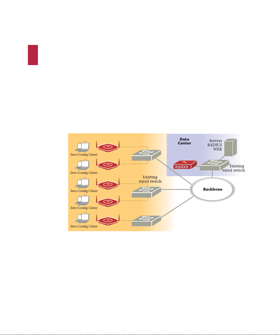
Access Points contain radio devices that communicate with the Controller and form the wireless LAN (WLAN). The Controller and Access Points connect to the site’s wired LAN through
wired switches. Wireless clients associate with the Access Point s as they roam throughout the
WLAN. As such, they are an extension of the wired LAN, providing the wireless benefits of client mobility, enhanced access, and dynamic network configuration.
Figure 1: Wireless LAN Connected to Network
AP
CONTROLLER
15
Page 30
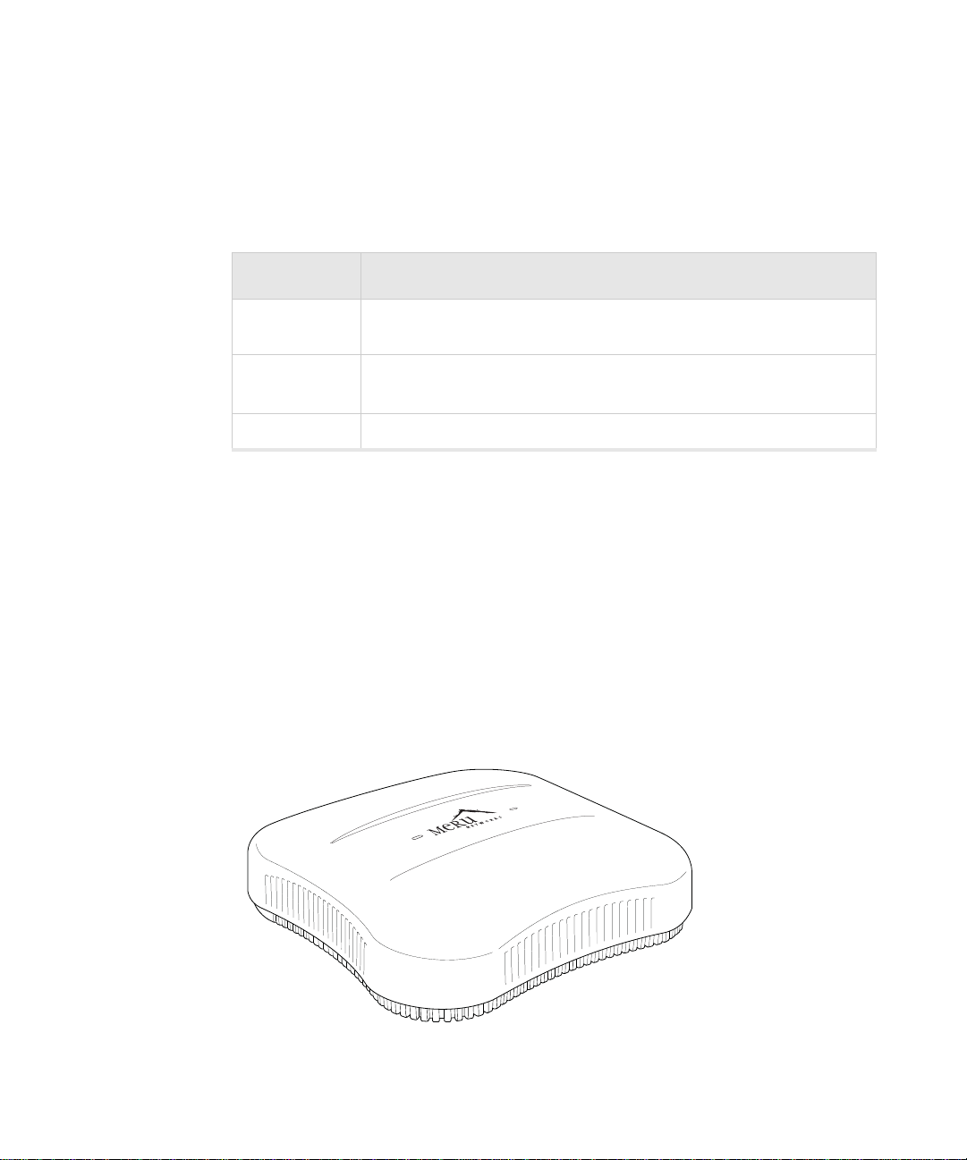
AP1000i
The AP1000i Access Point is an inte rnal-antenna AP with either one or tw o dual-band 802.11n
radios, 2x2 MIMO and internal antennas.
Model Configuration
AP1014i One single-band 802.11n radio with 2x2 MIMO, internal antennas, and
four wired ethernet ports.
AP1010i
AP1020i Two dual-band 802.11n radios with 2x2 MIMO and internal antennas
Features for the AP1000i include:
One single-band 802.11n radio with 2x2 MIMO and internal
antennas
• Internal antennas
• 802.11n suppport with channel bonding in both 2.4GHz and 5GHz frequency bands. Chan-
nel bonding combines two 20MHz channels into a single 40 MHz channel for increased
throughput.
• Plug and Play deployment using centralized controller platforms
• Multi-layered security including standard WPA2 features such as automatic traffic inspec-
tion
• Standard 802.3af PoE support and support for many 802.3at services
• Air Traffic Control technology for 802.11n devices and legacy a/b/g devices
Figure 2: AP1000i
AP1000i16
Page 31

AP1000e
The AP1000ie Access Point is an external-antenna AP with either one or two dual-band
802.11n radios, 2x2 MIMO and external antennas.
AP1010e One single-band 802.11n radio with 2x2 MIMO and external antennas
AP1020e Two dual-band 802.11n radios with 2x2 MIMO and external antennas
Features for the AP1000e include:
• External antennas
• 802.11n suppport with channel bonding in both 2.4GHz and 5GHz frequency bands. Chan-
• Plug and Play deployment using centralized controller platforms
• Multi-layered security including standard WPA2 features such as automatic traffic inspec-
• Standard 802.3af PoE support and support for many 802.3at services
• Air Traffic Control technology for 802.11n devices and legacy a/b/g devices
Figure 3: AP1020e
Model Configuration
nel bonding combines two 20MHz channels into a single 40 MHz channel for increased
throughput.
tion
AP1000e 17
Page 32

AP1000e18
Page 33

3 Installing AP1000i
AP1000i is supported by System Director versions 4.1 and greater. This chapter describes
how to install and configure an AP1000i. It contains the following sections:
• “Safety Precautions” on page 19
• “Best Practices for a Mixed Network” on page 19
• “Unpack the AP1000i” on page 20
• “Unpack the AP1000i” on page 20
• “Power Requirements” on page 21
• “Additional Equipment” on page 21
• “Installing AP1000i” on page 22
• “Restoring AP1000i Settings” on page 38
• “Check AP1000i LEDs” on page 39
• “Where to Go From Here” on page 41
Safety Precautions
IMPORTANT—Read and follow the regulatory instru ctions in Appendix B befo re inst alling and
operating this product.
The AP1000i is only intended for installation in Environment A as defined in IEEE 802.3af. All
directly interconnected equipment (e.g., equipment sharing an electrical source) must be contained within the same building, including the interconnected equipment's associated LAN
connection.
Best Practices for a Mixed Network
Read this section if you have both AP1000i and AP300 active simultaneously on the same
network. The following best practices should be followed to get optimal performance from
such a mixed network.
Safety Precautions 19
Page 34

• Care must be taken when deploying different AP types in the same physical area.
• STP (Spanning Tree Protocol) must be disabled on the switch for AP1020.
• If AP1000i and AP300 have overlapping coverage, you have two options: deploy them on
separate channels or make sure the ESS profiles on both AP types are unique. The chart
below shows two ESS scenarios, one supported, one not supported.
Supported ESS Scenario AP1000i Configuration AP300 Configuration
Two Unique ESS profiles ESS Profile name in controller
is UniqueName1
AP1000i and AP320i SSID
string over the air
Unsupported ESS
Scenario
Same ESS profiles ESS Profile name in controller
AP1000i and AP320i SSID
string over the air
Assumptions for the above best practices include:
Meru Meru
AP1000i Configuration AP300 Configuration
is same name
Meru Meru
ESS Profile name in controller
is UniqueName2
ESS Profile name in controller
is same name
• AP1000 models have Virtual Port disabled (recommended).
• AP300 models have Virtual Port enabled (recommended).
• AP1000is and AP300s are on the same channel. (AP1000i and AP320i could also be on
different channels.)
• AP1000is and AP320i are on the same controller. (AP1000i and AP320i could also be on
different controllers as long as each controller has a unique controller index.)
Unpack the AP1000i
AP1000i series uses both the dual radio (AP1020) and single radio (AP1010) models. Confirm
that the shipping box contains the following:
Unpack the AP1000i20
Page 35

• AP1000i ships with built-in ceiling mount clips. Each radio has two built-in antennas, so
AP1010 has two built-in antennas and AP1020 has four built-in antennas.
• Locking tool for ceiling mount locking. You can see a drawing of this in Figure 5 on
page 23.
If you want to lock AP1000i to the wall, you need the optional kit MNT-WMKIT-01.
Power Requirements
Radios on an AP1000i use 2x2 MIMO configuration. To power an AP1000i, use either an
802.3af or 802.3at PoE cable; either one works automatically with no configuration required.
For a list of supported PoEs, see the appendix “Supported Power Over Ethernet Devices for
Fortinet APs” on page 93
Additional Equipment
The following AP1000i mounting options require the listed additional equipment:
.
Installation Type Additional Equipment
Ceiling mounting on a suspended
ceiling with or without locking
Wall mounting
• Either an 802.3af or 802.3at PoE cable
• Either an 802.3af or 802.3at PoE cable
• Wall mount screws – Recommend #6, #8 (M3, M3.5)
Wall mounting with locking
• Either an 802.3af or 802.3at PoE cable
• Locking Kit 840-00052 MNT-WMKIT-01
Ceiling mounting with lowered
tiles
Power Requirements 21
• Either an 802.3af or 802.3at PoE cable
• Recessed Ceiling Mount Kit 840-0005x MNT-SCRM-
KIT-03 or -04
Page 36

Installing AP1000i
Select a Location
All AP1000i interconnected equipment must be contained within the same building, including
the interconnected equipment's associated LAN connection. Ceiling mounting is recommended but wall mounting is also supported. In addition , the AP1000i should be mounted in a
location that meets the following conditions:
• Relatively unobstructed access to the clients the AP serves. Select a location with minimal
physical obstructions between the AP and the wireless clients. We recommend planning for
about 20 data clients per radio (or per interference region) if you plan to use Virtual Port.
This is the recommendation for a data-only installation. Refer to the Fortinet Deployment
Guides on the support site for more information.
• In an office with cubicles, mount the APs below a hanging ceiling or on the wall near the
ceiling to provide the least obstructed communications path.
• On a wall, orient the AP1000i horizontally so that you can read the Fortinet logo without tilt-
ing your head at 90 degrees - this orientation provides optimum MIMO performance.
• AP1000i is designed to provide 180 degree directional coverage as illustrated below. Plan
placement with this pattern in mind.
Figure 4: Coverage Pattern for AP1000i When Ceiling Mounted
ceiling
• If you install AP1000i on a pole, keep in mind that coverage will be 180 degrees; the pattern
shown above would be directed sideways. We do not recommend mounting two AP1000is
back to back on a pole to achieve 360 degree coverage, however, because the two units
could interfere with each other.
Install the Access Point
You can mount AP1000i in any of the following ways:
• “Mount AP1000i Below a Suspended Ceiling” on page 23
• “Mount AP1000i on a Dropped Ceiling Bevel Tile” on page 25
• “Mount AP1000i on an Interlude T-Bar” on page 28
• “Mount AP1000i on a Wall” on page 31
• “Mount AP1000i on a Wall Using the Optional Locking Kit” on page 33
floor
Installing AP1000i22
Page 37

• “Set AP1000i on a Shelf” on page 34
00253
Key
UNLOCK
• “Mount AP1000i Above a Suspended Ceiling” on page 35
Mount AP1000i Below a Suspended Ceiling
AP1000i ships ready to mount below a suspended ceilin g; the built-in clip s snap on to a ceiling
rail. To mount an AP1000i below a suspended ceiling, follow these steps:
1. Remove the ceiling tiles at the location the AP will be mounted.
2. Be sure that AP1000i is not locked by inserting the locking key into the Unlock mechanism
as shown in Figure 5 on page 23 below.
Figure 5: Unlock AP1000i
3. Align the ceiling t-bar with the AP1000i slots indicated in Figure 6 on page 24 below.
Installing AP1000i 23
Page 38

Figure 6: Install AP1000i Below a Suspended Ceiling
T-bar
(in ceiling)
AP1000
00247
4. Press down on the tab indicated in Figure 6 on page 24 above and rotate the AP1000i
into place.
5. Connect one end of the CAT5 (or greater) Ethernet cable with PoE to the 100/1000 Ether-
net connector shown in Figure 7 on page 25 below.
Be sure to connect the Ethernet cable to the Ethernet port. The cable can mistakenly be plugged into
the Console port; if you do this, the AP won’t power up.
Installing AP1000i24
Page 39

Figure 7: AP1000i Ethernet Port
00254
AP1000 (mounted on ceiling)
LOCK
Key
00248
6. If you want to lock AP1000i in place, use the supplied locking tool to press the AP1 000i
locking mechanism shown in Figure 8 on page 25.
Figure 8: Optionally lock AP1000i
Installing AP1000i 25
7. To unlock AP1000i, press the unlocking mechanism on the opposite side of AP10 00i see
Figure 5 on page 23.
Page 40

Mount AP1000i on a Dropped Ceiling Bevel Tile
The mounting procedure for a ceiling that has recessed supports and low ered tiles is similar to
that of mounting on a suspended ceiling. However, this procedure requires a specialized
mounting bracket (ACC-MNT-SCRMKIT-03), as shown in Figure 9 on page 26.
Figure 9: Dropped Bevel Tile Mounting Bracket
1. Remove the ceiling tile alongside which the AP will be mounted.
2. Be sure that AP1000i is not locked by inserting the locking key into the Unlock mechanism
as shown in Figure 10 on page 27 below.
Installing AP1000i26
Page 41

Figure 10: Unlock AP1000i
00253
Key
UNLOCK
3. Align the mounting bracket with the AP1000i slots used for the ceiling t-bar in the previous
section (as shown in Figure 6 on page 24).
4. Press down on the tab indicated in Figure 6 on page 24 and rotate the AP1000i into place.
5. Push down on the thumbscrews provided on the mounting bracket and clip it to the ceiling
bar that will support the AP.
6. Tighten the screws to ensure that the mechanism stays locked in place.
7. Connect one end of the CAT5 (or greater) Ethernet cable with PoE to the 100/1000 Ether-
net connector shown in Figure 11 on page 28 below.
Be sure to connect the Ethernet cable to the Ethernet port. The cable can mistakenly be plugged into
the Console port; if you do this, the AP won’t power up.
Installing AP1000i 27
Page 42

Figure 11: AP1000i Ethernet Port
00254
AP1000 (mounted on ceiling)
LOCK
Key
00248
8. If you want to lock AP1000i in place, use the supplied locking tool to press the AP1000i
locking mechanism shown in Figure 12 on page 28.
Figure 12: Optionally lock AP1000i
Mount AP1000i on an Interlude T-Bar
9. To unlock AP1000i, press the unlocking mechanism on the opposite side of AP1000i see
Figure 10 on page 27.
The mounting procedure for a ceiling that has interlude T-Bar supports is similar to that of
mounting on a suspended ceiling. However, this procedure requires a specialized mounting
bracket (ACC-MNT-SCRMKIT-04), as depicted in Figur e13 on page 29.
Installing AP1000i28
Page 43

Figure 13: T-Bar Mounting Bracket
00253
Key
UNLOCK
1. Remove the ceiling tile alongside which the AP will be mounted .
2. Be sure that AP1000i is not locked by inserting the locking key into the Unlock mechanism
as shown in Figure 14 on page 29 below.
Figure 14: Unlock AP1000i
Installing AP1000i 29
Page 44

Align the mounting bracket with the AP1000i slots used for the ceiling t-bar in the previous
3.
section (as shown in Figure 6 on page 24).
4. Press down on the tab indicated in Figure 6 on page 24 and rotate the AP1000i into place.
5. Push down on the thumbscrews provided on the mounting bracket and clip it to the ceiling
bar that will support the AP.
6. Tighten the screws to ensure that the mechanism stays locked in place.
7. Connect one end of the CAT5 (or greater) Ethernet cable with PoE to the 100/1000 Ether-
net connector shown in Figure 15 on page 30 below.
Be sure to connect the Ethernet cable to the Ethernet port. The cable can mistakenly be plugged into
the Console port; if you do this, the AP won’t power up.
Figure 15: AP1000i Ethernet Port
00248
8. If you want to lock AP1000i in place, use the supplied locking tool to press the AP1000i
locking mechanism shown in Figure 16 on page 31.
Installing AP1000i30
Page 45

Figure 16: Optionally lock AP1000i
00254
AP1000 (mounted on ceiling)
LOCK
Key
9. To unlock AP1000i, press the unlocking mechanism on the opposite side of AP10 00i see
Figure 10 on page 27.
Mount AP1000i on a Wall
The AP1000i attaches directly to the wall. To mount an AP1000i on sheet rock or wall studs,
follow these steps:
1. Attach two appropriate screws (see “Additio na l Eq u i pment” on page 21 for screw informa-
tion) to the wall 3 inches apart (76mm) as shown below (Figure 17 on page 32).
Installing AP1000i 31
Page 46

Figure 17: AP1000i Wall Bracket
00250
Wall mount with screws.
00248
2. Attach the PoE Ethernet cable to the Ethernet port shown in Figure 18 on page 32.
Be sure to connect the Ethernet cable to the Ethernet port. The cable can mistakenly be plugged into
the Console port; if you do this. the AP won’t power up.
Figure 18: AP1000i Ethernet Port
3. Align the screws on the wall with the keyholes on the AP and slide the unit down slightly.
See Figure 17 on page 32.
Installing AP1000i32
Page 47

Mount AP1000i on a Wall Using the Optional Locking Kit
00251
Wall mount bracket
The AP1000i locking wall mount kit (840-00052 MNT-WMKIT-01)contains a wall bracket,
screws, and a locking key . To mount an AP1000i on sheetrock or wall studs with this kit, follow
these steps:
1. Attach AP1000i to the bracket as shown in Figure 19 on page 33.
Figure 19: Attach AP1000i to Wall Bracket
2. Insert the locking key and apply a small suitcase lock as shown in Figure 20 on page 34.
Installing AP1000i 33
Page 48

Figure 20: AP1000i Locked to a Wall
locking ky
LQJN\
Set AP1000i on a Shelf
Set AP1000i on any horizontal surface and then connect a PoE Ethernet cable.
Be sure to connect the Ethernet cable to the Ethernet port. The cable can mistakenly be plugged into
the Console port; if you do this. the AP won’t power up.
Figure 21: AP1000i Ethernet Port on the Left
00248
Installing AP1000i34
Page 49

Mount AP1000i Above a Suspended Ceiling
00253
Key
UNLOCK
AP1000i is not plenum-rated and should only be mounted above ceilings in non-plenum air space, such
as a return airflow for air conditioning.
Use the optional T-bar box hanger mounting kit to mount AP1000i above suspended ceiling Trails. The installation attaches the T-bar box hanger to the ceiling rails and then the AP1000i
attaches to the T-ba r box h anger. Note that AP1000i mounted above the ceiling has about 2-3
dBm less RF coverage than AP1000i mounted under the ceiling.
You may need to modify thicker tiles to support this installation.
When installed in air-handling spaces, such as above a suspended ceiling, power the AP1000i only with
a PoE, not a power supply.
To mount an AP1000i above the ceiling with the optional T-bar kit, follow these steps:
1. Determine the location on the ceiling rails where the AP will be mounted and remove the
ceiling tile.
2. Unpack the T-bar hanger kit.
3. Unlock the AP using the provided key.
Figure 22: Unlock AP1000i
Installing AP1000i 35
Page 50

Attach the mounting bar (depicted in Figure 23 on page 36) to the mounting brace (which
Mounting Brace
Mounting Bar
Clips attach to T-bar
4.
looks like a small handle) with the crossbar of the mounting kit sandwiched between
them. See Figure 24 on page 36.
Figure 23: Mounting Bar
Figure 24: Assembled Mounting Bracket
00624
5. Gently press the underside of the AP1000i against the mounting brace and rotate it into
place until the locking mechanism clicks. Note that this is essentially the same process as
depicted in Figure 6 on page 24.
6. Lock the AP1000i in place using the provided key.
Installing AP1000i36
Page 51

Figure 25: Lock AP1000i
00254
AP1000 (mounted on ceiling)
LOCK
Key
7. Attach the legs for the mounting kit to the T-Bars in the ceiling by sliding the clips d own
onto each respective bar.
8. Remove the top nut from each leg.
9. Lower the crossbar (with the AP attached) onto the legs and screw the nuts back on top of
the bar.
10. Connect one end of the PoE Ethernet cable to the Ethernet connector on the AP.
Installing AP1000i 37
Be sure to connect the Ethernet cable to the Ethernet port; the cable can mistakenly be plugged into the
Console port. If you do this. the AP won’t power up.
Use a shielded Cat 5e (or greater) Ethernet cable in order to comply with international electromagnetic
emissions limits.
Check that the AP1000i is operating correctly before replacing the ceiling tile to the ceiling.
Verify correct operation using the LEDs, as shown in “Check AP1000i LEDs” on page 39.
Page 52

Restoring AP1000i Settings
00248
Trigger the Restore mechanism to return the AP1000i to the factory default settings. This
overrides any changes that have been made from the controllers. Note that this restore mechanism differs from the ones on the other APs. Instead of a straigh t p a per clip, you n eed to u se
a paper clip bent at a right angle to push the mechanism trigger located on the inside as indicated in the Figure below . Access it through the sma ll hole with the bent p aper clip. Pre ss and
hold the button for 10 seconds. After 10 seconds, the AP reboots and comes back up with
default settings.
Figure 26: AP1000i Restore Button
Restoring AP1000i Settings38
Page 53

Check AP1000i LEDs
00249
LEDs
Status
LAN
Figure 27: AP1000i Status LEDs
Check AP1000i LEDs 39
Page 54

LED Color State
Status
(right LED)
LAN
(left LED)
The AP1000i has two LEDs, Status and LAN, as shown in Figure 27 on page 39. If you want
to change the appearance of the LEDS, follow these steps:
1. From the controller, click Configuration > Devices > AP, and then select the AP.
2. Select one of these settings for the LED Mode setting:
off AP is off - either there is no power or the LEDs are set
to Off on the controller. Check the LED setting on the
controller by clicking Configuration > Devices > AP,
selecting the AP and then checking the setting for
LED Mode.
cyan AP is booting stage 1.
green blinking AP is booting stage 2.
green/white alternating AP is discovering the controller.
green/blue alternating AP is downloading a configuration from the controller.
slow blue blinking AP is online and enabled.
rapid blue blinking AP is online and enabled and there is activity on one
or both radios.
red/yellow alternating Some AP failure occurred; check the controller for
more details about the alarm by clicking Monitor >
Alarms > Pending Alarms.
blue/yellow alternating AP is online and enabled and one or both radios are
either scanning or an admin has taken the radio(s)
down.
green LAN link is up.
green blinking LAN link is up and some activity is taking place.
red Link has either failed or has been brought down.
alternating green/
orange
Link is experiencing receive errors.
• Normal: LEDs are as described above
• Blink: Sets all LEDs flashing; this is useful to locate an AP
• Dark: Turns off all LEDs
3. Click OK.
Check AP1000i LEDs40
Page 55

Where to Go From Here
Now that the AP1000i is installed, go to the Meru System Director Getting Started
Guide for instructions on initializing the hardware. Return to this chapter to check the
status of the LEDs once the WLAN is operational; note that LED status is configurable,
so the chart above may not apply to APs whose status was reconfigured.
Where to Go From Here 41
Page 56

Where to Go From Here42
Page 57

4 Installing AP1000e
AP1000e is supported by System Director versions 5.1 and greater. This chapter describes
how to install and configure an AP1000e. It contains the following sections:
• “Safety Precautions” on page 43
• “Best Practices for a Mixed Network” on page 44
• “Unpack the AP1000e” on page 45
• “Power Requirements” on page 45
• “Additional Equipment” on page 45
• “Installing AP1000e” on page 46
• “Restoring AP1000e Settings” on page 53
• “Check AP1000e LEDs” on page 54
• “Where to Go From Here” on page 55
Safety Precautions
IMPORTANT—Read and follow the regulatory instru ctions in Appendix B befo re inst alling and
operating this product.
This product is intended to be supplied by a UL Listed power supply marked Class 2 or LPS and rated
minimum 5Vdc, 3A.
The AP1000e is only intended for installation in Environment A as d efined in IEEE 802.3af. All
directly interconnected equipment (e.g., equipment sharing an electrical source) must be contained within the same building, including the interconnected equipment's associated LAN
connection.
Safety Precautions 43
Page 58

Best Practices for a Mixed Network
Read this section if you have both AP1000e and AP300 active simultaneously on the same
network. The following best practices should be followed to get optimal performance from
such a mixed network.
• Care must be taken when deploying different AP types in the same physical area.
• If AP1000e and AP300 have overlapping coverage, you have two options: deploy them on
separate channels or make sure the ESS profiles on both AP types are unique. The chart
below shows two ESS scenarios, one supported, one not supported.
Supported ESS Scenario AP1000e Configuration AP300 Configuration
Two Unique ESS profiles ESS Profile name in controller
is UniqueName1
AP1000e and AP320i SSID
string over the air
Unsupported ESS Scenario AP1000e Configuration AP300 Configuration
Same ESS profiles ESS Profile name in controller
AP1000e and AP320i SSID
string over the air
Assumptions for the above best practices include:
Meru Meru
is same name
Meru Meru
ESS Profile name in controller
is UniqueName2
ESS Profile name in controller
is same name
• AP1000 models have Virtual Port disabled (recommended).
• AP300 models have Virtual Port enabled (recommended).
• AP1000es and AP300s are on the same channel. (AP1000e and AP320i could also be on
different channels.)
• AP1000es and AP320i are on the same controller. (AP1000e and AP320i could also be on
different controllers as long as each controller has a unique controller index.)
Best Practices for a Mixed Network44
Page 59

Unpack the AP1000e
AP1000e series employs a dual radio model—the AP1020e—which includes two anten nas for
each radio. Confirm that the shipping box contains the following:
• AP1000e
• Four (4) omnidirectional antennas
• Wall mount bracket
• Three (3) large screws (for attaching to the wall mount bracket)
• Four (4) rubber feet (for use when deploying on a horizontal surface)
Power Requirements
Radios on an AP1000e use 2x2 MIMO configuration. To power an AP1000e, use either an
802.3af or 802.3at PoE cable; either one works automatically with no configuration required.
For a list of supported PoEs, see the appendix “Supported Power Over Ethernet Devices for
Fortinet APs” on page 93
Additional Equipment
The following AP1000e mounting options require the listed additional equipment:
Installation Type Additional Equipment
Ceiling mounting on a suspended
ceiling
Wall mounting
Ceiling mounting with lowered tiles
Unpack the AP1000e 45
• Either an 802.3af or 802.3at PoE cable
• Either an 802.3af or 802.3at PoE cable
• Wall mount screws – Recommend #6, #8 (M3, M3.5)
• Either an 802.3af or 802.3at PoE cable
• Recessed Ceiling Mount Kit 840-0005x MNT-SCRM-
KIT-03 or -04
Page 60

Installing AP1000e
Select a Location
All AP1000e interconnected equipment must be contained wi thin th e same bui lding, including
the interconnected equipment's associated LAN connection. Ceiling mounting is recommended but wall mounting is also supported. In addition, the AP1000e should be mounted in a
location that meets the following conditions:
• Relatively unobstructed access to the clients the AP serves. Select a location with minimal
physical obstructions between the AP and the wireless clients. We recommend planning for
about 20 data clients per radio (or per interference region) if you plan to use Virtual Port.
This is the recommendation for a data-only installation. Refer to the Fortinet Deployment
Guides on the support site for more information.
• In an office with cubicles, mount the APs below a hanging ceiling or on the wall near the
ceiling to provide the least obstructed communications path.
• On a wall, orient the AP1000e horizontally so that you can read the Meru logo without tilting
your head at 90 degrees - this orientation provides optimum MIMO performance.
Install the Access Point
You can mount AP1000e in any of the following ways:
• “Mount AP1000e Below a Suspended Ceiling” on page 46
• “Mount AP1000e on a Dropped Ceiling Bevel Tile” on page 48
• “Mount AP1000e on an Interlude T-Bar” on page 49
• “Mount AP1000e on a Wall” on page 50
• “Mount AP1000e Above a Suspended Ceiling” on page 51
Mount AP1000e Below a Suspended Ceiling
AP1000e ships ready to mount below a suspended ceiling; the bu ilt-in clips snap onto a ceilin g
rail. To mount an AP1000e below a suspended ceiling, follow these steps:
1. Remove the ceiling tiles at the location the AP will be mounted.
2. Align the ceiling t-bar with the AP1000e slots indicated in Figure 28 on page 47 below.
Installing AP1000e46
Page 61

Figure 28: Install AP1000e Below a Suspended Ceiling
R
ES ET
USB
CON
SOLE
G
1
Console
port
Ethernet
port
USB
port
DC 5
V
T-bar
(in ceiling)
00261
3. Press down on the tab indicated in Figure 28 on page 47 above and rotate the AP1000e
into place.
4. Connect one end of the CAT5 (or greater) Ethernet cable with PoE to the 100/1000 Ether-
net connector shown in Figure 29 on page 47 below.
Be sure to connect the Ethernet cable to the Ethernet port. The cable can mistakenly be plugged into
the Console port; if you do this, the AP won’t power up.
Figure 29: AP1000e Ethernet Port
Installing AP1000e 47
Page 62

Mount AP1000e on a Dropped Ceiling Bevel Tile
The mounting procedure for a ceiling that has recessed supports and low ered tiles is similar to
that of mounting on a suspended ceiling. However, this procedure requires a specialized
mounting bracket (ACC-MNT-SCRMKIT-03), as shown in Figure 30 on page 48.
Figure 30: Dropped Bevel Tile Mounting Bracket
1. Remove the ceiling tile alongside which the AP will be mounted.
2. Align the mounting bracket with the AP1000e slots used for the ceiling t-bar in the previ-
ous section (as shown in Figure 28 on page 47).
3. Press down on the tab indicated in Figure 28 on page 47 and rotate the AP1000e into
place.
4. Push down on the thumbscrews provided on the mounting bracket and clip it to the ceiling
bar that will support the AP.
5. Tighten the screws to ensure that the mechanism stays locked in place.
6. Connect one end of the CAT5 (or greater) Ethernet cable with PoE to the 100/1000 Ether-
net connector shown in Figure 31 on page 49 below.
Be sure to connect the Ethernet cable to the Ethernet port. The cable can mistakenly be plugged into
the Console port; if you do this, the AP won’t power up.
Installing AP1000e48
Page 63

Figure 31: AP1000e Ethernet Port
R
ES ET
USB
CON
SOLE
G
1
Console
port
Ethernet
port
USB
port
DC 5
V
Mount AP1000e on an Interlude T-Bar
The mounting procedure for a ceiling that has interlude T-Bar supports is similar to that of
mounting on a suspended ceiling. However, this procedure requires a specialized mounting
bracket (ACC-MNT-SCRMKIT-04), as depicted in Figure32 on page 49.
Figure 32: T-Bar Mounting Bracket
1. Remove the ceiling tile alongside which the AP will be mounted .
2. Align the mounting bracket with the AP1000e slots used for the ceil ing t-b ar in th e pre vi-
ous section (as shown in Figure 28 on page 47).
3. Press down on the tab indicated in Figure 28 on page 47 and rotate the AP1000e into
place.
4. Push down on the thumbscrews provided on the mounting bracket and clip it to the ceiling
Installing AP1000e 49
bar that will support the AP.
5. Tighten the screws to ensure that the mechanism stays locked in place.
Page 64

Connect one end of the CAT5 (or greater) Ethernet cable with PoE to the 100/1000 Ether-
R
ES ET
USB
CON
SOLE
G
1
Console
port
Ethernet
port
USB
port
DC 5
V
6.
net connector shown in Figure 33 on page 50 below.
Be sure to connect the Ethernet cable to the Ethernet port. The cable can mistakenly be plugged into
the Console port; if you do this, the AP won’t power up.
Figure 33: AP1000e Ethernet Port
Mount AP1000e on a Wall
The AP1000e package includes a wall mount bracket that attaches directly to the wall. To
mount an AP1000e on sheet rock or wall studs, follow these steps:
1. Using the supplied wa ll mount bracke t as a gu ide, mark th e fo ur ho les on th e w all th at w ill
anchor the bracket in place. The four screws should be aligned to the four corners of the
bracket.
2. Drill the holes as marked and attach the wall mount bracket with four screws.
3. Attach the three mounting screws sup plied i n the AP100 0e p ackage to the correspo ndi ng
holes on the underside of the AP. The holes are indicated in th e figu re belo w, and are
highlighted by hexagons on the AP itself.
Figure 34: AP1000e Mounting Screw Locations
4. Align the mounting screws with their corresponding holes in the bracket and press the AP
against the wall.
Installing AP1000e50
Page 65

Slide the AP downwards until it locks into place. The plastic lever attached to the wall
R
ES ET
USB
CON
SOLE
G
1
Console
port
Ethernet
port
USB
port
DC 5
V
5.
mount kit will click, locking the device.
6. Connect the antennas to the ports on the AP.
7. Attach the PoE Ethernet cable to the Ethernet port shown in Figu re 35 on page 51.
Be sure to connect the Ethernet cable to the Ethernet port. The cable can mistakenly be plugged into
the Console port; if you do this. the AP won’t power up.
Figure 35: AP1000e Ethernet Port
Mount AP1000e Above a Suspended Ceiling
Use the optional T-bar box hanger mounting kit to mount AP1000e above suspended ceiling
T-rails. The installation attaches the T-bar box hanger to the ceiling rails and then the
AP1000e attaches to the T -bar box ha nger . N ote that AP1000e mounte d above the ceiling has
about 2-3 dBm less RF coverage than AP1000e mounted under the ceiling.
You may need to modify thicker tiles to support this installation.
When installed in air-handling spaces, such as above a suspended ceiling, power the AP1000e only
with a PoE, not a power supply.
To mount an AP1000e above the ceiling with the optional T-bar kit, follow these steps:
1. Determine the location on the ceiling rails where the AP will be mounted and remove the
ceiling tile.
2. Unpack the T-bar hanger kit.
3. Attach the mounting bar (depicted in Figure 36 on page 52) to the mounting brace (which
looks like a small handle) with the crossbar of the mounting kit sandwiched between
them. See Figure 37 on page 52.
Installing AP1000e 51
Page 66

Figure 36: Mounting Bar
Mounting Brace
Mounting Bar
Clips attach to T-bar
Figure 37: Assembled Mounting Bracket
00624
4. Gently press the underside of the AP1000e against the mounting brace and rotate it into
place until the locking mechanism clicks. Note that this is essentially the same process as
depicted in Figure 28 on page 47.
5. Attach the legs for the mounting kit to the T-Bars in the ceiling by sliding the clips down
onto each respective bar.
6. Remove the top nut from each leg.
7. Lower the crossbar (with the AP attached) onto the legs and screw the nuts back on top of
the bar.
Installing AP1000e52
Page 67

Connect one end of the PoE Ethernet cable to the Ethernet connector on the AP.
R
ES ET
USB
CON
SOLE
G
1
Console
port
Ethernet
port
USB
port
DC 5
V
8.
Be sure to connect the Ethernet cable to the Ethernet port; the cable can mistakenly be plugged into the
Console port. If you do this. the AP won’t power up.
Use a shielded Cat 5e (or greater) Ethernet cable in order to comply with international electromagnetic
emissions limits.
Check that the AP1000e is operating correctly before replacing the ceiling tile to the ceiling.
Verify correct operation using the LEDs, as shown in “Check AP1000e LEDs” on page 54.
Restoring AP1000e Settings
Trigger the Restore mechanism to return the AP1000e to the factory default settings. This
overrides any changes that have been made from the controllers. Note that this restore mechanism differs from the ones on the other APs. Instead of a straigh t p aper clip , you need to use
a paper clip bent at a right angle to push the mechanism trigger located on the inside as indicated in the Figure below . Access it thro ugh the sma ll hole with the bent p ape r clip. Press and
hold the button for 10 seconds. After 10 seconds, the AP reboots and comes back up with
default settings.
Figure 38: AP1000e Restore Button
Restoring AP1000e Settings 53
Page 68

Check AP1000e LEDs
Figure 39: AP1000e Status LEDs
LED Color State
Status
(right LED)
off AP is off - either there is no power or the LEDs
cyan AP is booting stage 1.
green blinking AP is booting stage 2.
green/white alternating AP is discovering the controller.
green/blue alternating AP is downloading a configuration from the con-
slow blue blinking AP is online and enabled.
rapid blue blinking AP is online and enabled and there is activity on
red/yellow alternating Some AP failure occurred; check the controller for
blue/yellow alternating AP is online and enabled and one or both radios
are set to Off on the controller. Check the LED
setting on the controller by clicking Configuration
> Devices > AP , selecting the AP and then checking the setting for LED Mode.
troller.
one or both radios.
more details about the alarm by clicking Monitor
> Alarms > Pending Alarms.
are either scanning or an admin has taken the
radio(s) down.
Check AP1000e LEDs54
Page 69

LED Color State
LAN
(left LED)
The AP1000e has two LEDs, Status and LAN, as shown in “Check AP1000e LEDs” on
page 54. If you want to change the appearance of the LEDS, follow these steps:
1. From the controller, click Configuration > Devices > AP, and then select the AP.
2. Select one of these settings for the LED Mode setting:
green LAN link is up.
green blinking LAN link is up and some activity is taking place.
red Link has either failed or has been brought down.
alternating green/orange Link is experiencing receive errors.
• Normal: LEDs are as described above
• Blink: Sets all LEDs flashing; this is useful to locate an AP
• Dark: Turns off all LEDs
3. Click OK.
Where to Go From Here
Now that the AP1000e is installed, go to the Fortinet System Director Getting Started
Guide for instructions on initializing the hardware. Return to this chapter to check the st atus of
the LEDs once the WLAN is operational; note that LED status is configurable, so the chart
above may not apply to APs whose status was reconfigured.
Where to Go From Here 55
Page 70

Where to Go From Here56
Page 71

5 Installing AP1014i
AP1014i is supported by System Director versions 5.3 and greater. This chapter describes
how to install and configure an AP1014i. It contains the following sections:
• “Safety Precautions” on page 57
• “Unpack the AP1014i” on page 57
• “Power Requirements” on page 58
• “Additional Equipment” on page 58
• “Installing AP1014i” on page 59
• “Restoring AP1014i Settings” on page 75
• “Check AP1014i LEDs” on page 76
• “Where to Go From Here” on page 77
Safety Precautions
IMPORTANT—Read and follow the regulatory instru ctions in Appendix B befo re inst alling and
operating this product.
The AP1014i is only intended for installation in Environment A as defined in IEEE 802.3af. All
directly interconnected equipment (e.g., equipment sharing an electrical source) must be contained within the same building, including the interconnected equipment's associated LAN
connection.
Unpack the AP1014i
AP1014i is a single-radio AP that provides four additional wired Ethernet ports. Confirm that
the shipping box contains the following:
• AP1014i
Safety Precautions 57
Page 72

• Locking tool for ceiling mount locking
If you want to lock AP1014i to the wall, you need the optional kit MNT-WMKIT-01.
Power Requirements
Radios on an AP1014i use 2x2 MIMO configuration. To power an AP1014i, use either an
802.3af or 802.3at PoE cable; either one works automatically with no configuration required.
For a list of supported PoEs, see the appendix “Supported Power Over Ethernet Devices for
Fortinet APs” on page 93
Additional Equipment
The following AP1014i mounting options require the listed additional equipment:
Installation Type Additional Equipment
Ceiling mounting on a suspended
ceiling with or without locking
Wall mounting
Wall mounting with locking
Ceiling mounting with lowered
tiles
• Either an 802.3af or 802.3at PoE cable
• Either an 802.3af or 802.3at PoE cable
• Wall mount screws – Recommend #6, #8 (M3, M3.5)
• Either an 802.3af or 802.3at PoE cable
• Locking Kit 840-00052 MNT-WMKIT-01
• Either an 802.3af or 802.3at PoE cable
• Recessed Ceiling Mount Kit 840-0005x MNT-SCRM-
KIT-03 or -04
Power Requirements58
Page 73

Installing AP1014i
ceiling
floor
Select a Location
All AP1014i interconnected equipment must be contained within the same building, including
the interconnected equipment's associated LAN connection. Ceiling mounting is recommended but wall mounting is also supported. In addition , the AP1014i shou ld be mounted in a
location that meets the following conditions:
• Relatively unobstructed access to the clients the AP serves. Select a location with minimal
physical obstructions between the AP and the wireless clients. We recommend planning for
about 20 data clients per radio (or per interference region) if you plan to use Virtual Port.
This is the recommendation for a data-only installation. Refer to the Fortinet Deployment
Guides on the support site for more information.
• In an office with cubicles, mount the APs below a hanging ceiling or on the wall near the
ceiling to provide the least obstructed communications path.
• On a wall, orient the AP1014i horizontally so that you can read the Meru logo without tilting
your head at 90 degrees - this orientation provides optimum MIMO performance.
• AP1014i is designed to provide 180 degree directional coverage as illustrated below. Plan
placement with this pattern in mind.
Figure 40: Coverage Pattern for AP1014i When Ceiling Mounted
• If you install AP1014i on a pole, keep in mind that coverage will be 180 degrees; the pattern
shown above would be directed sideways. We do not recommend mounting two AP1014is
back to back on a pole to achieve 360 degree coverage, however, because the two units
could interfere with each other.
Install the Access Point
You can mount AP1014i in any of the following ways:
• “Mount AP1014i Below a Suspended Ceiling” on page 60
• “Mount AP1014i on a Dropped Ceiling Bevel Tile” on page 62
• “Mount AP1014i on an Interlude T-Bar” on page 65
• “Mount AP1014i on a Wall” on page 68
• “Mount AP1014i on a Wall Using the Optional Locking Kit” on page 70
Installing AP1014i 59
Page 74

• “Set AP1014i on a Shelf” on page 71
00253
Key
UNLOCK
• “Mount AP1014i Above a Suspended Ceiling” on page 72
Mount AP1014i Below a Suspended Ceiling
AP1014i ships ready to mount below a suspended ceiling; the bui lt-in clips snap on to a ceili ng
rail. To mount an AP1014i below a suspended ceiling, follow these steps:
1. Remove the ceiling tiles at the location the AP will be mounted.
2. Be sure that AP1014i is not locked by inserting the locking key into the Unlock mechanism
as shown in Figure 41 on page 60 below.
Figure 41: Unlock AP1014i
3. Align the ceiling t-bar with the AP1014i slots indicated in Figure 42 on page 61 below.
Installing AP1014i60
Page 75

Figure 42: Install AP1014i Below a Suspended Ceiling
T-bar
(in ceiling)
AP1000
00247
4. Press down on the tab indicated in Figure 42 on page 61 above and rotate the AP1014i
into place.
5. Connect one end of the CAT5 (or greater) Ethernet cable with PoE to the 100/1000 Ether-
net connector shown in Figure 43 on page 62 below.
Be sure to connect the Ethernet cable to the green uplink port. The yellow ports can be used to connect
wired clients to the AP.
Installing AP1014i 61
Page 76

Figure 43: AP1014i Green Uplink Port
00248
00254
AP1000 (mounted on ceiling)
LOCK
Key
6. If you want to lock AP1014i in place, use the supplied locking tool to press the AP1014i
locking mechanism shown in Figure 44 on page 62.
Figure 44: Optionally lock AP1014i
Mount AP1014i on a Dropped Ceiling Bevel Tile
7. To unlock AP1014i, press the unlocking mechanism on the opposite side of AP1014i see
Figure 41 on page 60.
The mounting procedure for a ceiling that has recessed supports and low ered tiles is similar to
that of mounting on a suspended ceiling. However, this procedure requires a specialized
mounting bracket (ACC-MNT-SCRMKIT-03), as shown in Figure 45 on page 63.
Installing AP1014i62
Page 77

Figure 45: Dropped Bevel Tile Mounting Bracket
00253
Key
UNLOCK
1. Remove the ceiling tile alongside which the AP will be mounted .
2. Be sure that AP1014i is not locked by inserting the locking key into the Unlock mechanism
as shown in Figure 46 on page 63 below.
Figure 46: Unlock AP1014i
Installing AP1014i 63
Page 78

Align the mounting bracket with the AP1014i slots used for the ceiling t-bar in the previous
00248
3.
section (as shown in Figure 42 on page 61).
4. Press down on the tab indicated in Figure 42 on page 61 and rotate the AP1014i into
place.
5. Push down on the thumbscrews provided on the mounting bracket and clip it to the ceiling
bar that will support the AP.
6. Tighten the screws to ensure that the mechanism stays locked in place.
7. Connect one end of the CAT5 (or greater) Ethernet cable with PoE to the 100/1000 Ether-
net connector shown in Figure 47 on page 64 below.
Be sure to connect the Ethernet cable to the green uplink port. The yellow ports can be used to connect
wired clients to the AP.
Figure 47: AP1014i Green Uplink Port
8. If you want to lock AP1014i in place, use the supplied locking tool to press the AP1014i
locking mechanism shown in Figure 48 on page 65.
Installing AP1014i64
Page 79

Figure 48: Optionally lock AP1014i
00254
AP1000 (mounted on ceiling)
LOCK
Key
9. To unlock AP1014i, press the unlocking mechanism on the opposite side of AP10 14i see
Figure 46 on page 63.
Mount AP1014i on an Interlude T-Bar
The mounting procedure for a ceiling that has interlude T-Bar supports is similar to that of
mounting on a suspended ceiling. However, this procedure requires a specialized mounting
bracket (ACC-MNT-SCRMKIT-04), as depicted in Figure49 on page 66.
Installing AP1014i 65
Page 80

Figure 49: T-Bar Mounting Bracket
00253
Key
UNLOCK
1. Remove the ceiling tile alongside which the AP will be mounted.
2. Be sure that AP1014i is not locked by inserting the locking key into the Unlock mechanism
as shown in Figure 46 on page 63 below.
Figure 50: Unlock AP1014i
3. Align the mounting bracket with the AP1014i slots used for the ceiling t-bar in the previous
section (as shown in Figure 42 on page 61).
Installing AP1014i66
Page 81

Press down on the tab indicated in Figure 42 on page 61 and rotate the AP1014i into
00248
4.
place.
5. Push down on the thumbscrews provided on the mounting bracket and clip it to the ceiling
bar that will support the AP.
6. Tighten the screws to ensure that the mechanism stays locked in place.
7. Connect one end of the CAT5 (or greater) Ethernet cable with PoE to the 100/1000 Ether-
net connector shown in Figure 51 on page 67 below.
Be sure to connect the Ethernet cable to the green uplink port. The yellow ports can be used to connect
wired clients to the AP.
Figure 51: AP1014i Green Uplink Port
8. If you want to lock AP1014i in place, use the supplied locking tool to press the AP1 014i
locking mechanism shown in Figure 48 on page 65.
Installing AP1014i 67
Page 82

Figure 52: Optionally lock AP1014i
00254
AP1000 (mounted on ceiling)
LOCK
Key
9. To unlock AP1014i, press the unlocking mechanism on the opposite side of AP1014i see
Figure 46 on page 63.
Mount AP1014i on a Wall
The AP1014i attaches directly to the wall. To mount an AP1014i on sheet rock or wall studs,
follow these steps:
1. Attach two appropriate screws (see “Additional Equipment” on pa ge 58 for screw informa-
tion) to the wall 3 inches apart (76mm) as shown below (Figure 53 on page 69).
Installing AP1014i68
Page 83

Figure 53: AP1014i Wall Bracket
00250
Wall mount with screws.
00248
2. Attach the PoE Ethernet cable to the Ethernet port shown in Figu re 54 on page 69.
Be sure to connect the Ethernet cable to the green uplink port. The yellow ports can be used to connect
wired clients to the AP.
Figure 54: AP1014i Green Uplink Port
3. Align the screws on the wall with the keyholes on the AP and slide the unit do wn sl ight ly.
See Figure 53 on page 69.
Installing AP1014i 69
Page 84

Mount AP1014i on a Wall Using the Optional Locking Kit
00251
Wall mount bracket
The AP1014i locking wall mount kit (840-00052 MNT-WMKIT-01)contains a wall bracket,
screws, and a locking key . To mount an AP1014i on sheetrock or wall studs with this kit, follow
these steps:
1. Attach AP1014i to the bracket as shown in Figure 55 on page 70.
Figure 55: Attach AP1014i to Wall Bracket
2. Insert the locking key and apply a small suitcase lock as shown in Figure 56 on page 71.
Installing AP1014i70
Page 85

Figure 56: AP1014i Locked to a Wall
locking ky
LQJN\
00248
Set AP1014i on a Shelf
Installing AP1014i 71
Set AP1014i on any horizontal surface and then connect a PoE Ethernet cable.
Be sure to connect the Ethernet cable to the green uplink port. The yellow ports can be used to connect
wired clients to the AP.
Figure 57: AP1014i Green Uplink Port
Page 86

Mount AP1014i Above a Suspended Ceiling
00253
Key
UNLOCK
AP1014i is not plenum-rated and should only be mounted above ceilings in non-plenum air space, such
as a return airflow for air conditioning.
Use the optional T-bar box hanger mounting kit to mount AP1014i above suspended ceiling Trails. The installation attaches the T-bar box hanger to the ceiling rails and then the AP1014i
attaches to the T-ba r box h anger. Note that AP1014i mounted above the ceilin g has about 2-3
dBm less RF coverage than AP1014i mounted under the ceiling.
You may need to modify thicker tiles to support this installation.
When installed in air-handling spaces, such as above a suspended ceiling, power the AP1014i only with
a PoE, not a power supply.
To mount an AP1014i above the ceiling with the optional T-bar kit, follow these steps:
1. Determine the location on the ceiling rails where the AP will be mounted and remove the
ceiling tile.
2. Unpack the T-bar hanger kit.
3. Unlock the AP using the provided key.
Figure 58: Unlock AP1014i
Installing AP1014i72
Page 87

Attach the mounting bar (depicted in Figure 59 on page 73) to the mounting brace (which
Mounting Brace
Mounting Bar
Clips attach to T-bar
4.
looks like a small handle) with the crossbar of the mounting kit sandwiched between
them. See Figure 60 on page 73.
Figure 59: Mounting Bar
Figure 60: Assembled Mounting Bracket
00624
5. Gently press the underside of the AP1014i against the mounting brace and rotate it into
place until the locking mechanism clicks. Note that this is essentially the same process as
depicted in Figure 42 on page 61.
6. Lock the AP1014i in place using the provided key.
Installing AP1014i 73
Page 88

Figure 61: Lock AP1014i
00254
AP1000 (mounted on ceiling)
LOCK
Key
7. Attach the legs for the mounting kit to the T-Bars in the ceiling by sliding the clips down
onto each respective bar.
8. Remove the top nut from each leg.
9. Lower the crossbar (with the AP attached) onto the legs and screw the nuts back on top of
the bar.
10. Con nect one en d of the PoE Ethernet cabl e to the Etherne t conne ctor on the AP.
Be sure to connect the Ethernet cable to the green uplink port. The yellow ports can be used to connect
wired clients to the AP.
Installing AP1014i74
Page 89

Figure 62: AP1014i Green Uplink Port
00248
00248
Use a shielded Cat 5e (or greater) Ethernet cable in order to comply with international electromagnetic
emissions limits.
Check that the AP1014i is operating correctly before replacing the ceiling tile to the ceiling.
Verify correct operation using the LEDs, as shown in “Check AP1014i LEDs” on page 76.
Restoring AP1014i Settings
Trigger the Restore mechanism to return the AP1014i to the factory default settings. This
overrides any changes that have been made from the controllers. Note that this restore mechanism differs from the ones on the other APs. Instead of a straigh t p aper clip , you need to use
a paper clip bent at a right angle to push the mechanism trigger located on the inside as indicated in the Figure below . Access it thro ugh the sma ll hole with the bent p ape r clip. Press and
hold the button for 10 seconds. After 10 seconds, the AP reboots and comes back up with
default settings.
Figure 63: AP1014i Restore Button
Restoring AP1014i Settings 75
Page 90

Check AP1014i LEDs
00249
LEDs
Status
LAN
Figure 64: AP1014i Status LEDs
Check AP1014i LEDs76
Page 91

LED Color State
Status
(right LED)
LAN
(left LED)
If you want to change the appearance of the LED, follow these steps:
1. From the controller, click Configuration > Devices > AP, and then select the AP.
2. Select one of these settings for the LED Mode setting:
off AP is off - either there is no power or the LEDs are set
to Off on the controller. Check the LED setting on the
controller by clicking Configuration > Devices > AP,
selecting the AP and then checking the setting for LED
Mode.
cyan AP is booting stage 1.
green blinking AP is booting stage 2.
green/white alternating AP is discovering the controller.
green/blue alternating AP is downloading a configuration from the controller.
slow blue blinking AP is online and enabled.
rapid blue blinking AP is online and enabled and there is activity on one or
both radios.
red/yellow alternating Some AP failure occurred; check the controller for
more details about the alarm by clicking Monitor >
Alarms > Pending Alarms.
blue/yellow alternating AP is online and enabled and one or both radios are
either scanning or an admin has taken the radio(s)
down.
Off This LED is not used, and will always be off.
• Normal: LED is as described above
• Blink: Sets the LED flashing; this is u s ef ul to locate an AP
• Dark: Turns off the LED
3. Click OK.
Where to Go From Here
Now that the AP1014i is installed, go to the Fortinet System Director Getting S tarted Guide
for instructions on initializing the hardware. Return to this chapter to check the status of the
LEDs once the WLAN is operational; note that LED status is configurable, so the chart above
may not apply to APs whose status was reconfigured.
Where to Go From Here 77
Page 92

Where to Go From Here78
Page 93

A Cautions and Warnings
The cautions and warnings that appear in this manual are listed below in English, German,
French, and Spanish.
Cautions
A Caution calls your attention to a possible hazard that can damage equipment.
"Vorsicht” weist auf die Gefahr einer möglichen Beschädigung des Gerätes in.
Une mise en garde attire votre attention sur un risque possible d'endommagement de l'équi-
pement. Ci-dessous, vous trouverez les mises en garde utilisées dans ce manuel.
Un mensaje de precaución le advierte sobre un posible peligro que pueda dañar el equipo.
Las siguientes son precauciones utilizadas en este manual.
When changing the orientation of the antennas, be sure to slightly loosen the knurled ring before moving the antenna. Retighten the ring afterward. Otherwise, you might damage the internal cabling in the
AP.
Bei einer Neuausrichtung der Antennen muss vor Bewegung der Antenne der Rändelring leicht gelockert werden. Anschließend den Ring wieder festziehen. Anderenfalls können die internen Kabel im AP
beschädigt werden.
En cas de modification d’orientation des antennes, veiller à desserrer légèrement la bague moletée
avant de réorienter l’antenne. Resserrer ensuite la bague, faute de quoi le câblage interne du point
d’accès pourrait être endommagé.
Al cambiar la orientación de las antenas, asegúrese de aflojar ligeramente el anillo estriado antes de
mover la antena. Luego vuelva a apretar el anillo. De otro modo, podría dañar el cableado interno del
punto de acceso.
Cautions 79
Page 94

Be sure to connect the Ethernet cable to the Ethernet port; the cable can mistakenly be plugged into the
Console port.
Darauf achten, dass das Ethernetkabel am Ethernetanschluss und nicht versehentlich am Konsolenanschluss angeschlossen wird.
Veiller à bien connecter le câble Ethernet au port Ethernet et non pas au port Console.
Asegúrese de conectar el cable Ethernet al puerto Ethernet, porque por error se puede enchufar en el
puerto de la consola.
The radiated output power of the access points is well below the FCC radio frequency exposure limits.
However, the Fortinet Access Point should be used in such a manner that the potential for human contact during normal operation is minimized. To avoid the possibility of exceeding the FCC radio frequency exposure limits, you should keep a distance of at least 20 cm between you (or any other person
in the vicinity) and the Access Point antennas.
Die abgestrahlte Ausgangsleistung von Geräten von Fortinet, Inc. liegt weit unter den HochfrequenzExpositionsgrenzwerten der FCC. Die Fortinet Access Point Zugangspunkte von Fortinet, Inc. sollten
jedoch so verwendet werden, dass das Potenzial für Kontakt mit Menschen während des normalen
Betriebs auf ein Mindestmaß beschränkt wird. Um die Möglichkeit einer Überschreitung der FCC-Hochfrequenz-Expositionsgrenzwerte zu vermeiden, ist ein Abstand von mindestens 20 cm zwischen Ihnen
(bzw. einer anderen Person in der Nähe) und den Zugangspunkt-Antennen zu wahren.
La puissance de rayonnement émise par les équipements Fortinet, Inc. est très inférieure aux limites
d'exposition aux fréquences radio définies par la FCC. Toutefois, les points d'accès de la série Fortinet
Access Point de Fortinet, Inc. doivent être utilisés de façon à éliminer tout risque de contact humain en
fonctionnement normal. Pour éviter de dépasser les limites d'exposition aux fréquences radio définies
par la FCC, il est impératif de préserver en permanence une distance supérieure ou égale à 20 cm
entre l'utilisateur (ou toute personne se trouvant à proximité) et les antennes du point d'accès.
La potencia de radiación de los dispositivos de Fortinet, Inc. está muy por debajo de los límites de
exposición a radiofrecuencia estipulados por la FCC. No obstante, los puntos de acceso de la serie
Fortinet Access Point de Fortinet, Inc. deben usarse de tal manera que se minimice la posibilidad de
contacto para el usuario durante la operación normal. Para evitar la posibilidad de exceder los límites
de exposición a radiofrecuencia establecidos por la FCC, el usuario (o cualquier otra persona en torno)
debe mantenerse a una distancia de al menos 20 cm respecto a las antenas del punto de acceso.
Cautions80
Page 95

Exposure to Radio Frequency Radiation.
The installer of this radio equipment must ensure that the antenna is located or pointed such that it does
not emit an RF field in excess of Health Canada limits for the general population; consult Safety Code 6,
obtainable from Health Canada’s website http://www.hc-sc.gc.ca/rpb.
Exposure to Radio Frequency Radiation.
The installer of this radio equipment must ensure that the antenna is located or pointed such that it does
not emit an RF field in excess of Health Canada limits for the general population; consult Safety Code 6,
obtainable from Health Canada's website http://www.hc-sc.gc.ca/rpb.
Exposition aux rayonnements à fréquence radioélectrique
L'installateur de cet équipement radio doit veiller à positionner et orienter l'antenne de telle sorte qu'elle
n'émette pas un champ radioélectrique supérieur aux limites définies par Santé Canada pour la population générale. Consulter le Code de sécurité n° 6, disponible sur le site Web de Santé Canada à
l'adresse http://www.hc-sc.gc.ca/rpb.
Exposición a la radiación de radiofrecuencia.
El instalador de este equipo de radio debe cerciorarse de que la antena está localizada u orientada de
tal manera que no emita un campo de radiofrecuencia superior a los límites estipulados por Health
Canada para la población; consulte el Código de Seguridad 6 que podrá encontrar en el página web de
Health Canada, http://www.hc-sc.gc.ca/rpb.
Warnings
A warning calls your attention to a possible hazard that can cause injury or death. The following are the warnings used in this manual.
"Achtung" weist auf eine mögliche Gefährdung hin, die zu Verletzungen oder Tod führen können. Sie finden die folgenden Warnhinweise in diesem Handbuch:
Un avertissement attire votre attention sur un risque possible de blessure ou de décès. Cidessous, vous trouverez les avertissements utilisés dans ce manuel.
Warnings 81
Page 96

Una advertencia le llama la atención sobre cualquier posible peligro que pueda ocasionar
daños personales o la muerte. A continuación se dan las advertencias utilizadas en este manual.
With plastic covers removed, this product is suitable for use in environmental air space in accordance
with the Section 300-22(c) of the National Electric Code and Sections 2- 128.12 - 010 (3) and 12 - 100
of the Canadian Electrical Code. Part 1. C22. 1. For other countries, consult local authorities for regulations.
Bei abgenommener Kunststoffabdeckung ist dieses Produkt zur Verwendung in einem Umgebungsluftraum gemäß Abschnitt 300-22(c) des National Electric Code und Abschnitt 2- 128.12 - 010 (3) und
12 - 100 des Canadian Electrical Code Teil 1. C22.1 geeignet. Die Vorschriften für andere Länder sind
bei den örtlichen Behörden erhältlich.
Sous réserve que ses couvercles de plastique soient déposés, cet appareil est adapté à une utilisation
dans les vides de construction des bâtiments selon la section 300-22(c) du code NEC (National Electric
Code) et les sections 2- 128.12 - 010 (3) et 12 - 100 du Code électrique du Canada, partie 1. C22. 1.
Pour tous les autres pays, consulter les organismes de réglementation locaux.
Una vez desprendidas las cubiertas de plástico, este producto es adecuado para su uso en el espacio
aéreo circundante en conformidad con la sección 300-22(c) del National Electric Code (Código Eléctrico Nacional de EE.UU.) y las secciones 2- 128.12 - 010 (3) y 12 - 100 del Código Eléctrico de
Canadá. Parte 1. C22. 1. En otros países, consulte a las autoridades locales competentes para informarse acerca de las normativas vigentes.
Any Fast Ethernet (FE) cables installed in air-handling spaces should be suitable under NEC Article
800.50 and marked accordingly for use in plenums and air-handling spaces with regard to smoke propagation, such as CL2-P, CL3-P, MPP (Multi Purpose Plenum), or CMP (Communications Plenum).
Alle Fast-Ethernet (FE)-Kabel, die in Lüftungsräumen installiert werden, sollten gemäß NEC Artikel
800.50 geeignet sein und entsprechend zur Verwendung in Hohlräumen (Plenum) und Lüftungsräumen
im Hinblick auf Rauchausbreitung gekennzeichnet sein, z.B. CL2-P, CL3-P, MPP (Multi Purpose Plenum) oder CMP (Communications Plenum).
Les câbles Fast Ethernet (FE) installés dans un vide d’air doivent correspondre aux critères de l’article
800.50 du code NEC et identifiés en conséquence comme adaptés à une utilisation dans les vides de
construction des bâtiments en matière de propagation de la fumée (marquages CL2-P, CL3-P, MPP
(Multi Purpose Plenum) ou CMP (Communications Plenum)).
Todos los cables Fast Ethernet (FE) instalados en espacios aéreos deben cumplir con el artículo
800.50 del NEC y estar marcados adecuadamente para su uso en espacios aéreos y plenums en lo
concerniente a la propagación de humo, tales como CL2-P, CL3-P, MPP (Plenum multifuncional), o
CMP (Plenum de comunicaciones).
Warnings82
Page 97

Inside antennas must be positioned to observe minimum separation of 20 cm. (~ 8 in.) from all users
and bystanders. For the protection of personnel working in the vicinity of inside (downlink) antennas,
the following guidelines for minimum distances between the human body and the antenna must be
observed.
The installation of the indoor antenna must be such that, under normal conditions, all personnel cannot
come within 20 cm. (~ 8.0 in.) from any inside antenna. Exceeding this minimum separation will ensure
that the employee or bystander does not receive RF-exposure beyond the Maximum Permissible Exposure according to FCC CFR 47, section 1.1310 i.e. limits for General Population/Uncontrolled Exposure.
Innenantennen müssen so positioniert werden, dass ein Mindestabstand von 20 cm (ca. 8 Zoll) zu allen
Benutzern und anderen Personen gewahrt wird. Zum Schutz von Personal, das in der Nähe von
Innenantennen (Downlink) arbeitet, sind die folgenden Richtlinien für Mindestabstand zwischen dem
menschlichen Körper und der Antenne zu beachten.
Die Innenantenne muss so installiert werden, dass sich unter normalen Bedingungen kein Personal bis
auf weniger als 20 cm (ca. 8 Zoll) an eine Innenantenne annähern kann. Durch Überschreitung dieses
Mindestabstands wird sichergestellt, dass Mitarbeiter oder andere Personen keiner RF-Exposition über
die maximal zulässige Exposition (MPE; Maximum Permissible Exposure) gemäß FCC CFR 47,
Abschnitt 1.1310 (Grenzwerte für die allgemeine Bevölkerung/unkontrollierte Exposition) ausgesetzt
werden.
Les antennes intérieures doivent être positionnées de façon à respecter une distance minimum de 20
cm par rapport aux utilisateurs et aux tiers. Pour la protection du personnel travaillant à proximité des
antennes intérieures (liaison descendante), respecter les directives suivantes pour assurer des distances minimales entre les êtres humains et les antennes.
Toute antenne intérieure doit être installée de telle sorte que, dans des conditions normales, le personnel ne puisse s'en approcher à moins de 20 cm. Cette distance minimale est destinée à garantir qu'un
employé ou un tiers ne sera pas exposé à un rayonnement radioélectrique supérieur à la valeur maximale autorisée, telle qu'elle est définie dans les limites d'exposition non contrôlées pour la population
par la réglementation de la FCC CFR 47, section 1.1310.
Las antenas interiores deben colocarse de manera que se observe una separación mínima de 20 cm.
(~ 8 pulg.) respecto a todos los usuarios y circunstantes. Para la protección del personal que trabaje en
las inmediaciones de las antenas interiores (receptoras), deben observarse las siguientes directrices
relativas a la distancia mínima entre el cuerpo humano y la antena.
La instalación de la antena interior debe efectuarse de tal modo que, en condiciones normales, ningún
miembro del personal pueda acercarse a menos de 20 cm. (~ 8,0 pulg.) de cualquier antena interior. El
cumplimiento de este mínimo de separación asegura que el empleado o circunstante no recibirá
exposición a radiofrecuencia por encima de la Exposición Máxima Permisible conforme a la normativa
FCC CFR 47, sección 1.1310, es decir, los límites asignados a la Exposición Incontrolada/Población
Civil.
Warnings 83
Page 98

Warnings84
Page 99

B Regulatory Information
The Meru Access Point (APs) must be installed and used in strict accordance with the manufacturer’s instructions as described in the user documentation that comes with the product.
For country-specific approvals, see belo w . Meru Ne tworks, Inc. is not responsible for any radio
or television interference caused by unauthorized modification of APs, or the substitution or
attachment of connecting cables and equipment other than that specified by Meru Networks,
Inc. The correction of interference caused by such unauthorized modification, substitution or
attachment is the responsibility of the user . Meru Networks, Inc. and it s authorized rese llers or
distributors are not liable for any damage or violation of government regulations that may arise
from the user failing to comply with these guidelines.
USA
Underwriters Laboratories
Use only with Listed I.T.E. equipment.
Notices
The unit is intended for installation in Environment A as defined in IEEE 802.3.af. All interconnected equipment must be contained within the same building, including the interconnected
equipment's associated LAN connection.
Suitable for use in environmental air space in accordance with Section 300-22(c) of the
National Electrical Code, and Sections 2-128, 12-010(3) and 12-100 of the Canadian Electrical Code, Part 1, C22.1.
USA 85
Page 100

FCC Radiation Exposure Statement
The radiated output power of the Fortinet devices is well below the FCC radio frequency exposure limits. However, the Access Point should be used in such a manner that the potential for human contact
during normal operation is minimized. When installing and operating these devices, keep a minimum
distance of 20 cm (8 inches) between the antennas and any persons/users in the vicinity.
Radio Frequency Interference Requirements
Fortinet Access Points
All devices except the OAP180 are indoor devices. The FCC requires indoor use for the frequency
range 5.15 GHz to 5.25 GHz to reduce the potential for harmful interference to co-channel Mobile Satellite systems.
High-power radars are allocated as primary users of the 5.25 to 5.35 GHz and 5.65 to 5.85 GHz bands.
These radar stations can cause interference with or damage to these devices, or both.
Interference Statement
This device complies with Part 15 of the FCC Rules. Operation is subject to the following two
conditions: (1) This device may not cause harmful interference, and (2) this device must
accept any interference received, including interference that may cause undesired operation.
This equipment has been tested and found to comply with the limits for a Class B digital
device, pursuant to Part 15 of the FCC Rules. These limits are desig ned to provide reasonable
protection against harmful interference in a residential installation. This equipment gen erates,
uses, and can radiate radio frequency energy. If the equipment is not installed and used in
accordance with the instructions, the equipment may cause harmful interference to radio communications. There is no guarantee, however, that such interference will not occur in a particular installation. If this equipment does cause harmful interference to radio or television
reception (which can be determined by turning the equipment off and on), the user is encouraged to try to correct the interference by taking one or more of the following measures:
• Increase the separation betw e e n th e e qu i pment and receiver.
• Connect the equipment into an outlet on a circuit different from to which the receiver is con-
nected.
• Consult the dealer or an experienced radio/TV technician for help.
The Fortinet Access Point must be installed and used in strict accordance with the manufacturer’s
instructions as described in the user documentation that comes with the product. Any other installation
or use may violate FCC Part 15 regulations. Modifications not expressly approved by Fortinet, Inc.
could void your authority to operate the equipment.
USA86
 Loading...