

Page 1

FortiSwitch-548B
Version 5.2.0.2
Administration Guide
Page 2

FortiSwitch-548B Administration Guide
Version 5.2.0.2
Revision 6
December 11, 2012
Copyright© 2012 Fortinet, Inc. All rights reserved. Fortinet®, FortiGate®, and FortiGuard®, are
registered trademarks of Fortinet, Inc., and other Fortinet names herein may also be trademarks of
Fortinet. All other product or company names may be trademarks of their respective owners. Fortinet
reserves the right to change, modify, transfer, or otherwise revise this publication without notice, and the
most current version of the publication shall be applicable.
Regulatory compliance
FCC Class A Part 15 CSA/CUS
Page 3

Table of Contents
1. Introduction ................................................................................................................ 6
1.1 Scope ................................................................................................................. 6
1.2 Documentation .................................................................................................... 6
1.3 Customer Service and Technical Support ........................................................... 6
1.4 Training ............................................................................................................... 6
2. Product Overview....................................................................................................... 8
2.1 Switch Description .............................................................................................. 8
2.2 Features ............................................................................................................. 8
2.3 Front-Panel Components .................................................................................. 10
2.4 LED Indicators .................................................................................................. 10
2.5 Rear Panel Description ..................................................................................... 10
2.6 Management Options ........................................................................................ 11
2.7 Web-based Management Interface ................................................................... 11
2.8 Command Line Console Interface Through the Serial Port or Telnet ................. 11
2.9 SNMP-Based Management .............................................................................. 11
3. Installation and Quick Startup................................................................................... 13
3.1 Package Contents............................................................................................. 13
3.2 Switch Installation ............................................................................................. 14
3.3 Installing the Switch in a Rack .......................................................................... 15
3.4 Quick Starting the Switch .................................................................................. 16
3.5 System Information Setup ................................................................................. 17
4. Console and Telnet Administration Interface ............................................................ 21
4.1 Local Console Management ............................................................................. 21
4.2 Set Up your Switch Using Console Access ....................................................... 21
4.3 Set Up your Switch Using Telnet Access ........................................................... 23
5. Web-Based Management Interface ................................ .......................................... 24
5.1 Overview ........................................................................................................... 24
5.2 How to log in ..................................................................................................... 25
5.3 Web-Based Management Menu ........................................................................ 26
6. Command Line Interface Structure and Mode-based CLI ......................................... 30
6.1 CLI Command Format ...................................................................................... 30
6.2 CLI Mode-based Topology ................................................................................ 31
7. Switching Commands .............................................................................................. 33
7.1 System Information and Statistics commands ................................................... 33
- 3 -
Page 4

7.2 Device Configuration Commands...................................................................... 41
7.3 Management Commands ................................................................................ 152
7.4 Spanning Tree Commands .............................................................................. 202
7.5 System Log Management Commands ............................................................ 222
7.6 Script Management Commands ...................................................................... 229
7.7 User Account Management Commands .......................................................... 231
7.8 Security Commands ........................................................................................ 237
7.9 CDP (Cisco Discovery Protocol) Commands .................................................. 269
7.10 SNTP (Simple Network Time Protocol) Commands ........................................ 274
7.11 MAC-Based Voice VLAN Commands ............................................................. 280
7.12 LLDP (Link Layer Discovery Protocol) Commands .......................................... 284
7.13 Denial Of Service Commands ................................................................ ......... 301
7.14 VTP (VLAN Trunking Protocol) Commands ..................................................... 310
7.15 Protected Ports Commands ............................................................................ 316
7.16 Static MAC Filtering Commands ..................................................................... 318
7.17 System Utilities ............................................................................................... 321
7.18 DHCP Snooping Commands .......................................................................... 342
7.19 IP Source Guard (IPSG) Commands .............................................................. 350
7.20 Dynamic ARP Inspection (DAI) Command ...................................................... 353
7.21 Differentiated Service Command .................................................................... 360
7.22 ACL Command ............................................................................................... 389
7.23 IPv6 ACL Command ....................................................................................... 397
7.24 CoS (Class of Service) Command .................................................................. 401
7.25 Domain Name Server Relay Commands ........................................................ 408
8. Routing Commands ............................................................................................... 414
8.1 Address Resolution Protocol (ARP) Commands ............................................. 414
8.2 IP Routing Commands .................................................................................... 420
8.3 Open Shortest Path First (OSPF) Commands ................................................. 432
8.4 BOOTP/DHCP Relay Commands ................................................................... 468
8.5 Routing Information Protocol (RIP) Commands .............................................. 471
8.6 Router Discovery Protocol Commands ........................................................... 479
8.7 VLAN Routing Commands .............................................................................. 483
8.8 Virtual Router Redundancy Protocol (VRRP) Commands ............................... 484
9. IP Multicast Commands ......................................................................................... 493
9.1 Distance Vector Multicast Routing Protocol (DVMRP) Commands .................. 493
9.2 Internet Group Management Protocol (IGMP) Commands .............................. 498
9.3 MLD Commands ............................................................................................. 507
- 4 -
Page 5

9.4 Multicast Commands ................................ ...................................................... 513
9.5 Protocol Independent Multicast – Dense Mode (PIM-DM) Commands ............ 519
9.6 Protocol Independent Multicast – Sparse Mode (PIM-SM) Commands ........... 523
9.7 IGMP Proxy Commands ................................................................................. 532
9.8 MLD Proxy Commands ................................................................................... 537
10. IPv6 Commands .................................................................................................... 542
10.1 Tunnel Interface Commands ........................................................................... 542
10.2 Loopback Interface Commands ...................................................................... 544
10.3 IPv6 Routing Commands ................................................................................ 546
10.4 OSPFv3 Commands ....................................................................................... 566
10.5 RIPng Commands .......................................................................................... 597
10.6 Protocol Independent Multicast – Dense Mode (PIM-DM) Commands ............ 602
10.7 Protocol Independent Multicast – Sparse Mode (PIM-SM) Commands ........... 605
11. Web-Based Management Interface ................................ ........................................ 614
11.1 Overview ......................................................................................................... 614
11.2 System Menu .................................................................................................. 615
11.3 Switching Menu .............................................................................................. 695
11.4 Routing Menu ................................................................................................. 784
11.5 Security Menu ................................................................................................. 839
11.6 IPv6 Menu ...................................................................................................... 861
11.7 QOS Menu ...................................................................................................... 893
11.8 IPv4 Multicast Menu ........................................................................................ 926
11.9 IPv6 Multicast Menu ........................................................................................ 951
- 5 -
Page 6

1. Introduction
1.1 Scope
This document describes:
how to install the FortiSwitch-548B switch (the Switch)
how to use the CLI console to manage the Switch
how to use the web-based management interface to configure the Switch
1.2 Documentation
The Fortinet Technical Documentation web site, http://docs.fortinet.com, provides the most up-to-date
versions of Fortinet publications, as well as additional technical documentation such as technical notes.
1.2.1 Fortinet Knowledge Base
The Fortinet Knowledge Base provides additional Fortinet technical documentation, such as
troubleshooting and how-to-articles, examples, FAQs, technical notes, a glossary, and more. Visit the
Fortinet Knowledge Base at http://kb.fortinet.com.
1.2.2 Comments on Fortinet Technical Documentation
Please send information about any errors or omissions in this or any Fortinet technical document to
techdoc@fortinet.com.
1.3 Customer Service and Technical Support
Fortinet Technical Support provides services designed to make sure that your Fortinet products install
quickly, configure easily, and operate reliably in your network.
To learn about the technical support services that Fortinet provides, visit the Fortinet Technical Support
web site at https://support.fortinet.com.
You can dramatically improve the time that it takes to resolve your technical support ticket by providing
your configuration file, a network diagram, and other specific information. For a list of required
information, see the Fortinet Knowledge Center article What does Fortinet Technical Support require in
order to best assist the customer?T
1.4 Training
Fortinet Training Services provides classes that orient you quickly to your new equipment, and
certifications to verify your knowledge level. Fortinet provides a variety of training programs to serve the
needs of our customers and partners world-wide.
- 6 -
Page 7

To learn about the training services that Fortinet provides, visit the Fortinet Training Services web site at
http://campus.training.fortinet.com, or email them at training@fortinet.com.
- 7 -
Page 8

2. Product Overview
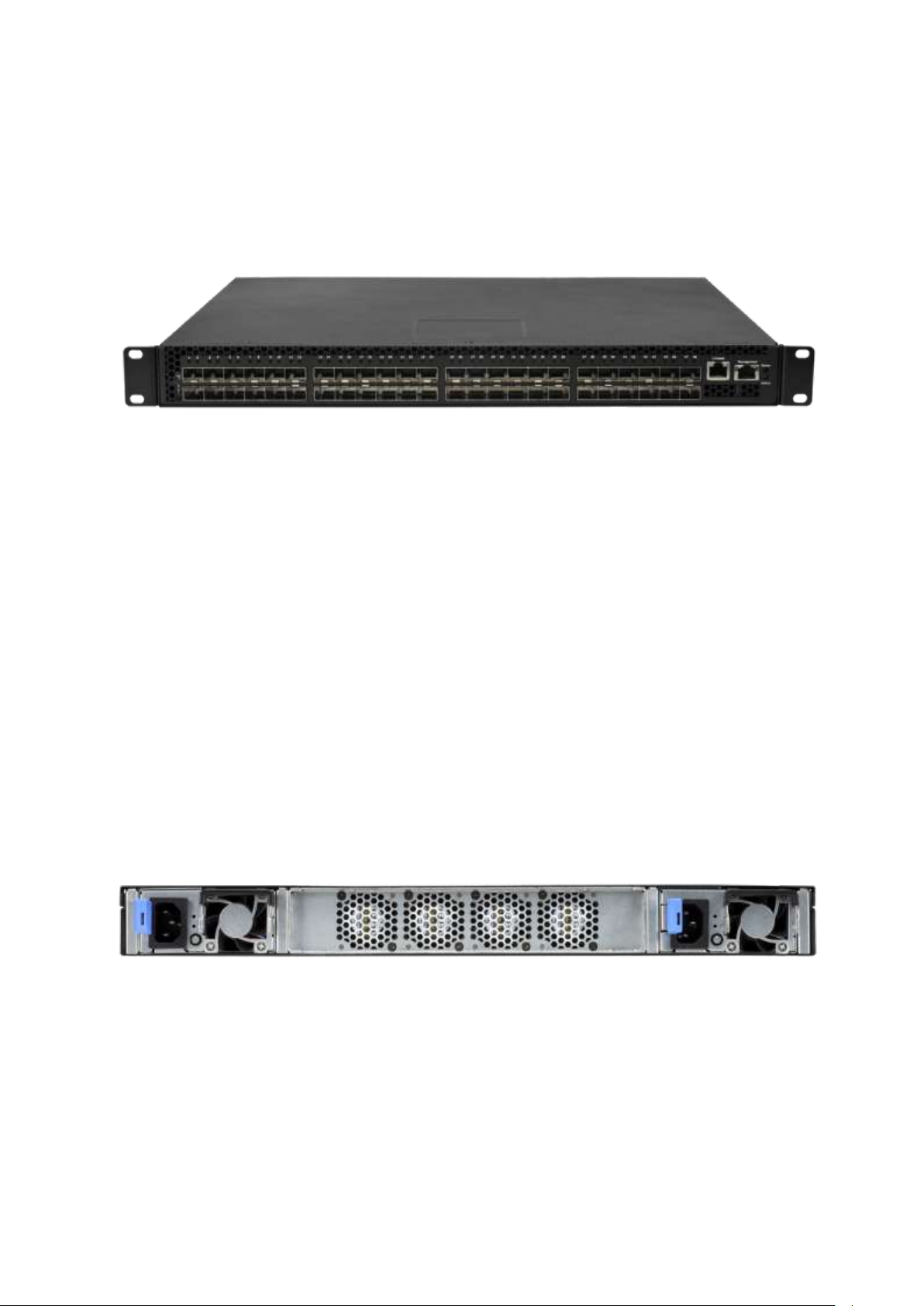
2.1 Switch Description
FortiSwitch-548B is a layer 2 SFP+ 10-Gigabit Ethernet backbone switch designed for adaptability and
scalability. The Switch provides a management platform and uplink to backbone. Alternatively, the
Switch can utilize up to 48 10-Gigabit Ethernet ports to function as a central distribution hub for other
switches, switch groups, or routers. The built-in 1000/100/10 Ethernet port is for out of service. The
FortiSwitch-548B power system provides two power supplies. The FortiSwitch-548B SFP+ port also
provides 1-Gigabit speed by manual settings.
2.2 Features
Supports 48 SFP+ 10-Gigabit Ethernet ports
1 built-in 1000/100/10 Ethernet port for out of band switch mangement.
Support two power supplies -- Software will detect power failure and read information(what power
install on your system)
IEEE 802.3z and IEEE 802.3x compliant Flow Control for all 10-Gigabit ports
Supports 802.1D STP, 802.1S MSTP, and 802.1w Rapid Spanning Tree for redundant back up
bridge paths
Supports 802.1Q VLAN, Protocol-based VLAN, Subnet-based VLAN, MAC-based VLAN, Protected
Port, Double VLAN, Voice VLAN, GVRP, GMRP, IGMP snooping, 802.1p Priority Queues, Port
Channel, port mirroring
Supports VTP (VLAN Trunking Protocol)
Supports CDP
Supports LLDP with potential communication problems detection
Supports Port Security
Multi-layer Access Control (based on MAC address, IP address, VLAN, Protocol, 802.1p, DSCP)
Quality of Service (QoS) customized control
802.1x (port-based) access control and RADIUS Client support
TACACS+ support
Administrator-definable port security
Supports DHCP Snooping, Dynamic ARP Inspection and IP Source Guard (IPSG)
ARP support
IP Routing support
OSPF v2 and v3 support
RIP v1/v2 and RIPng support
Router Discovery Protocol support
Virtual Router Redundancy Protocol (VRRP) support
- 8 -
Page 9

VLAN routing support
IP Multicast support
IGMP v1, v2, and v3 support
DVMRP support
Protocol Independent Multicast - Dense Mode (PIM-DM) support for IPv4 and IPv6
Protocol Independent Multicast - Sparse Mode (PIM-SM) support for IPv4 and IPv6
Supports DHCPv6 protocol, OSPFv3 protocol, Tunneling, loopback
Allows to configure IPv6 routing interface, routing preference
DHCP Client and Relay support
DNS Client and Relay support
Per-port bandwidth control
SNMP v.1, v.2, v.3 network management, RMON support
Supports Web-based management
CLI management support
Fully configurable either in-band or out-of-band control via RS-232 console serial connection
Telnet remote control console
TraceRoute support
Traffic Segmentation
TFTP/FTP upgrade
SysLog support
Simple Network Time Protocol support
Web GUI Traffic Monitoring
SSH Secure Shell version 1 and 2 support
SSL Secure HTTP TLS Version 1 and SSL version 3 support
Fibre Channel Over Ethernet (FCoE)
FIP Snooping
Data Center Bridge(DCB) -- Enhanced Transmission Selection(ETS, IEEE 802.1Qaz); Priority Flow
Control(PFC, IEEE 802.1Qbb); Congestion Notification(CN, IEEE 802.1Qau)
- 9 -
Page 10
2.3 Front-Panel Components
The front panel of the Switch consists of 48 10-Gigabit interfaces, 2 LED indicators, 1 built-in
1000/100/10 RJ-45 Ethernet service ports, an RS-232 communication port, and 48 port LEDs.
The upper LED indicators display power status. The lower LED indicators displays the status of the
switch. An RS-232 DCE console port is for setting up and managing the Switch via a connection to a
console terminal or PC using a terminal emulation program. Each port LED has two colors: Color green
represents port link status; Color Orange represents port activity status and it will be blinking if the port
has an activity.
2.4 LED Indicators
The Status LED indicator represnts status of the switch. The Power LED indicator represent power ON
or OFF.
2.5 Rear Panel Description
The rear panel of the Switch contains Dual Redundant AC power connector and Four Fans. The four
fans can be built in back-to-front and front-to-back(depend on customer requirement).
The AC power connector is a standard three-pronged connector that supports the power cord. Plug the
female connector of the provided power cord into this socket, and the male side of the cord into a power
outlet. The Switch automatically adjusts its power setting to any supply voltage in the range from 100 ~
240 VAC at 50 ~ 60 Hz.
- 10 -
Page 11

!
To access the Switch through a Web browser, the computer running the Web browser must
have IP-based network access to the Switch.
2.6 Management Options
The system may be managed by using one Service Ports through a Web Browswer,Telent, SNMP
function and using the console port on the front panel through CLI command.
2.7 Web-based Management Interface
After you have successfully installed the Switch, you can configure the Switch, monitor the LED panel,
and display statistics graphically using a Web browser, such as Mozilla FireFox (version 3.6 or higher) or
Microsoft® Internet Explorer (version 5.0 or above).
2.8 Command Line Console Interface Through the Serial Port or Telnet
You can also connect a computer or terminal to the serial console port or use Telnet to access the
Switch. The command-line-driven interface provides complete access to all switch management
features.
2.9 SNMP-Based Management
You can manage the Switch with an SNMP-compatible console program. The Switch supports SNMP
version 1.0, version 2.0, and version 3.0. The SNMP agent decodes the incoming SNMP messages and
responds to requests with MIB objects stored in the database. The SNMP agent updates the MIB objects
to generate statistics The Switch supports a comprehensive set of MIB extensions:
RFC1643 Ether-like MIB
RFC1493 Bridge
RFC 2819 RMON
RFC 2233 Interface MIB
RFC 2571 (SNMP Frameworks)
RFC 2572 (Message Processing for SNMP)
RFC 2573 (SNMP Applications)
RFC 2576 (Coexistence between SNMPs)
RFC 2618 (Radius-Auth-Client-MIB)
RFC 2620 (Radius-Acc-Client-MIB)
RFC 1724 (RIPv2-MIB)
RFC 1850 (OSPF-MIB)
RFC 1850 (OSPF-TRAP-MIB)
- 11 -
Page 12

RFC 2787 (VRRP-MIB)
RFC 3289 - DIFFSERV-DSCP-TC
RFC 3289 - DIFFSERV-MIB
QOS-DIFFSERV-EXTENSIONS-MIB
QOS-DIFFSERV-PRIVATE-MIB
RFC 2674 802.1p
RFC 2932 (IPMROUTE-MIB)
Fortinet Enterprise MIB
ROUTING-MIB
MGMD-MIB
RFC 2934 PIM-MIB
DVMRP-STD-MIB
IANA-RTPROTO-MIB
MULTICAST-MIB
FASTPATH-ROUTING6-MIB
IEEE8021-PAE-MIB
INVENTORY-MIB
MGMT-SECURITY-MIB
QOS-ACL-MIB
QOS-COS-MIB
RFC 1907 - SNMPv2-MIB
RFC 2465 - IPV6-MIB
RFC 2466 - IPV6-ICMP-MIB
TACACS-MIB
USM-TARGET-TAG-MIB
IGMP/MLD Snooping
IGMP/MLD Layer2 Multicast
QoS – IPv6 ACL
Voice VLAN
Guest VLAN
LLDP MED
RFC 2925 (DISMAN-TRACEROUTE-MIB)
RFC 2080 (RIPng)
OSPFV3-MIB
- 12 -
Page 13

3. Installation and Quick Startup
3.1 Package Contents
Before you begin installing the Switch, confirm that your package contains the following items:
One FortiSwitch-548B Layer 2 10-Gigabit Managed Switch
Mounting kit: 2 mounting brackets and screws
Four rubber feet with adhesive backing
One AC power cord
This User’s Guide with Registration Card
CLI Reference
CD-ROM with User’s Guide and CLI Reference
- 13 -
Page 14
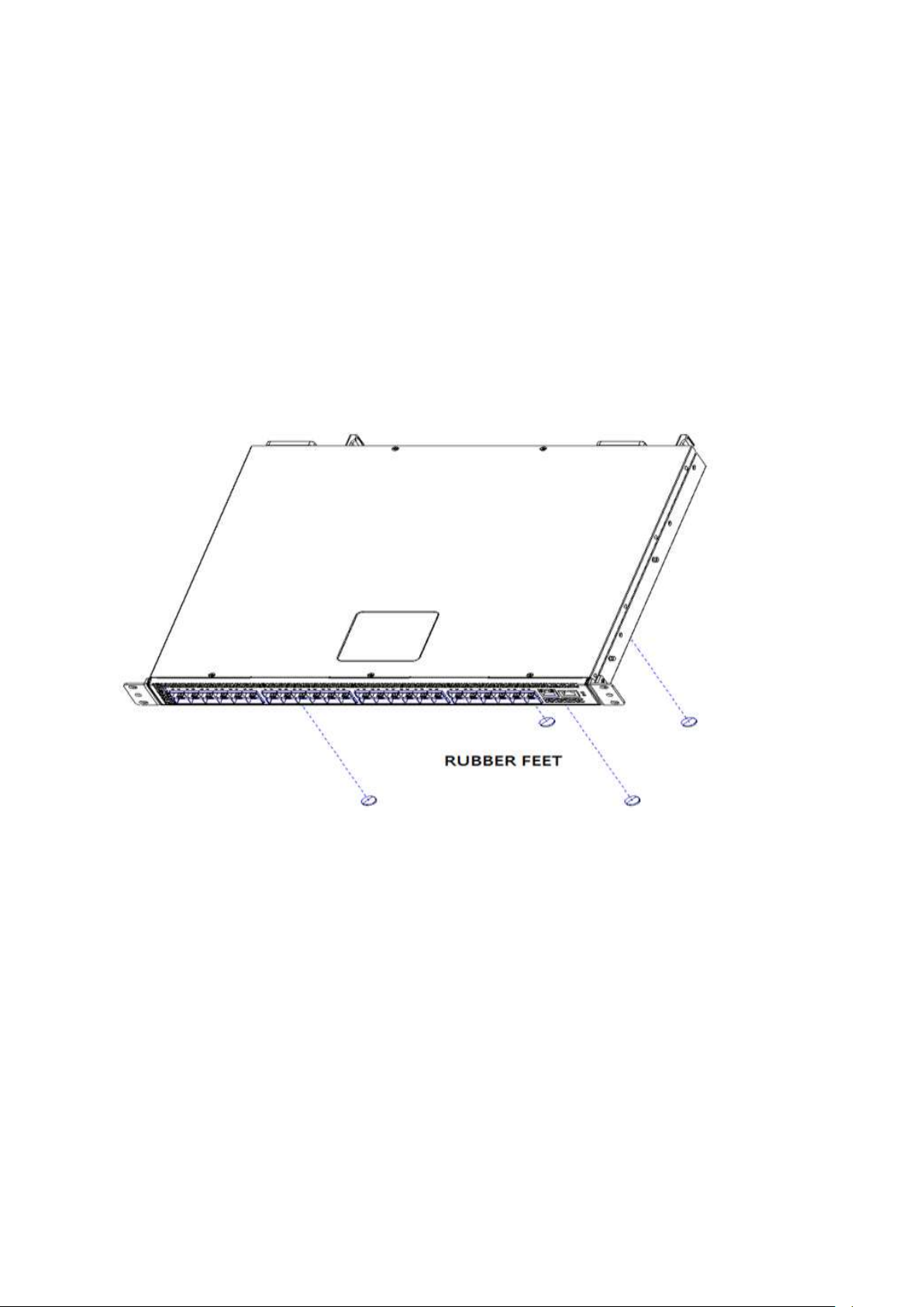
3.2 Switch Installation
Installing the Switch Without the Rack
1. Install the Switch on a level surface that can safely support the weight of the Switch and its attached
cables. The Switch must have adequate space for ventilation and for accessing cable connectors.
2. Set the Switch on a flat surface and check for proper ventilation. Allow at least 5 cm (2 inches) on
each side of the Switch and 15 cm (6 inches) at the back for the power cable.
3. Attach the rubber feet on the marked locations on the bottom of the chassis.
The rubber feet are recommended to keep the unit from slipping.
- 14 -
Page 15
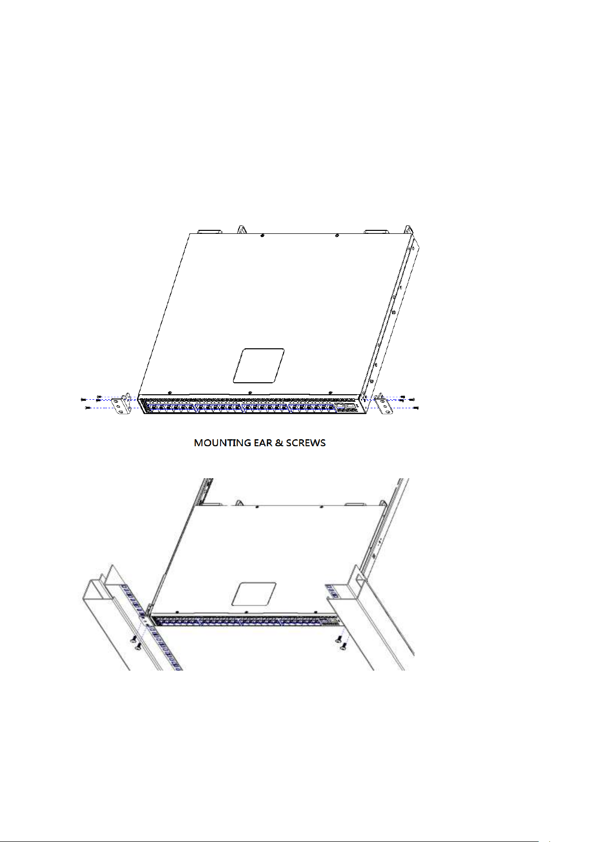
3.3 Installing the Switch in a Rack
You can install the Switch in most standard 19-inch (48.3-cm) racks. Refer to the illustrations below.
1. Use the supplied screws to attach a mounting bracket to each side of the Switch.
2. Align the holes in the mounting bracket with the holes in the rack.
3. Insert and tighten two screws through each of the mounting brackets.
- 15 -
Page 16

3.4 Quick Starting the Switch
1. Read the device Installation Guide for the connectivity procedure. In-band connectivity allows access
to the FortiSwitch-548B Series Switch locally. From a remote workstation,the device must be
configured with IP information (IP address, subnet mask, and default gateway).
2. Turn the Power ON.
3. Allow the device to load the software until the login prompt appears. The device initial state is called
the default mode.
4. When the prompt asks for operator login, do the following:
Type the word admin in the login area. Since a number of the Quick Setup commands require
administrator account rights, FORTINET suggests logging into an administrator account.
Do not enter a password because there is no password in the default mode.
Press the <Enter> key
The CLI Privileged EXEC mode prompt will be displayed.
Use “configure” to switch to the Global Config mode from Privileged EXEC.
Use “exit” to return to the previous mode.
- 16 -
Page 17

Command
Details
show hardware
Allows the user to see the HW & SW version
the device contains
System Description - switch's model name
show version
Allows the user to see Serial Number, Part
Number, and Model name
See SW loader, bootrom and operation
version
See HW version
Command
Details
show Interface status { <slot/port> |
all}
Displays the Ports slot/port
Type - Indicates if the port is a special type of
port
Admin Mode - Selects the Port Control
Administration State
Physical Mode - Selects the desired port
speed and duplex mode
Physical Status - Indicates the port speed and
duplex mode
Link Status - Indicates whether the link is up
or down
Link Trap - Determines whether or not to send
a trap when link status changes
LACP Mode - Displays whether LACP is
enabled or disabled on this port
Flow Mode - Indicates the status of flow
control on this port
Cap. Status - Indicates the port capabilities
during auto-negotiation
Command
Details
show users
Displays all users that are allowed to access
the switch
User Access Mode - Shows whether the user
is able to change parameters on the switch
3.5 System Information Setup
3.5.1 Quick Start up Software Version Information
Table 2-1. Quick Start up Software Version Information
3.5.2 Quick Start up Physical Port Data
Table 2-2. Quick Start up Physical Port
3.5.3 Quick Start up User Account Management
Table 2-3. Quick Start up User Account Management
- 17 -
Page 18

(Read/Write) or is only able to view (Read
Only).
As a factory default, admin has Read/Write
access and guest has Read Only access.
There can only be one Read/Write user and
up to 5 Read Only users.
show loginsession
Displays all login session information
username <username> {passwd |
nopasswd}
Allows the user to set passwords or change
passwords needed to login
A prompt will appear after the command is
entered requesting the old password. In the
absence of an old password leave the area
blank. The operator must press enter to
execute the command.
The system then prompts the user for a new
password then a prompt to confirm the new
password. If the new password and the
confirmed password match a message will be
displayed.
The user password should not be more than
eight characters in length.
copy running-config startup-config
[filename]
This will save passwords and all other
changes to the device.
If you do not save config, all configurations will
be lost when a power cycle is performed on
the switch or when the switch is reset.
Command
Details
show ip interface
Displays the Network Configurations
IP Address - IP Address of the interface
Default IP is 192.168.2.1
Subnet Mask - IP Subnet Mask for the
interface. Default is 255.255.255.0
Default Gateway - The default Gateway for
this interface
Default value is 0.0.0.0
Burned in MAC Address - The Burned in MAC
Address used for inband connectivity
Network Configurations Protocol Current Indicates which network protocol is being
used. Default is none
3.5.4 Quick Start up IP Address
To view the network parameters the operator can access the device by the following three methods.
Simple Network Management Protocol - SNMP
Telnet
Web Browser
Table 2-4. Quick Start up IP Address
- 18 -
Page 19

Management VLAN Id - Specifies VLAN id
Web Mode - Indicates whether HTTP/Web is
enabled.
Java Mode - Indicates whether java mode is
enabled.
ip address
(Config)#interface vlan 1
(if-vlan 1)#ip address <ipaddr> <netmask>
(if-vlan 1)#exit
(Config)#ip default-gateway <gateway>
IP Address range from 0.0.0.0 to
255.255.255.255
Subnet Mask range from 0.0.0.0 to
255.255.255.255
Gateway Address range from 0.0.0.0 to
255.255.255.255
Displays all of the login session information
Command
Details
copy startup-config xmodem
<filename>
This starts the upload and displays the mode
of uploading and the type of upload it is and
confirms the upload is taking place.
For example:
If the user is using HyperTerminal, the user
must specify where the file is going to be
received by the pc.
Command
Details
copy xmodem startup-config
<filename>
Sets the download datatype to be an image or
config file.
The URL must be specified as: xmodem:
filepath/ filename
For example:
If the user is using HyperTerminal, the user
must specify which file is to be sent to the
switch. The Switch will restart automatically
once the code has been downloaded.
Command
Details
3.5.5 Quick Start up Uploading from Switch to Out-of-Band PC
Table 2-5. Quick Start up Uploading from Switch to Out-of-Band PC (XMODEM)
3.5.6 Quick Start up Downloading from Out-of-Band PC to Switch
Table 2-6 Quick Start up Downloading from Out-of-Band PC to Switch
3.5.7 Quick Start up Downloading from TFTP Server
Before starting a TFTP server download, the operator must complete the Quick Start up for the
IPAddress.
Table 2-7 Quick Start up Downloading from TFTP Server
- 19 -
Page 20

copy <url> startup-config <filename>
Sets the download datatype to be an image or
config file.
The URL must be specified as:
tftp://ipAddr/filepath/fileName.
The startup-config option downloads the
config file using tftp and image option
downloads the code file.
Command
Details
clear config
Enter yes when the prompt pops up to clear all
the configurations made to the switch.
copy running-config startup-config
[filename]
Enter yes when the prompt pops up that asks
if you want to save the configurations made to
the switch.
reload
Enter yes when the prompt pops up that asks
if you want to reset the system.
You can reset the switch or cold boot the
switch; both work effectively.
3.5.8 Quick Start up Factory Defaults
Table 2-8 Quick Start up Factory Defaults
- 20 -
Page 21

4. Console and Telnet Administration Interface
This chapter discusses many of the features used to manage the Switch, and explains many concepts
and important points regarding these features. Configuring the Switch to implement these concepts is
discussed in detail in chapter 6.
4.1 Local Console Management
Local console management involves the administration of the Switch via a direct connection to the
RS-232 DCE console port. This is an Out-of-band connection, meaning that it is on a different circuit
than normal network communications, and thus works even when the network is down.
The local console management connection involves a terminal or PC running terminal emulation
software to operate the Switch’s built-in console program (see Chapter 6). Using the console program, a
network administrator can manage, control, and monitor many functions of the Switch. Hardware
components in the Switch allow it to be an active part of a manageable network. These components
include a CPU, memory for data storage, other related hardware, and SNMP agent firmware. Activities
on the Switch can be monitored with these components, while the Switch can be manipulated to carry
out specific tasks.
4.2 Set Up your Switch Using Console Access
Out-of-band management requires connecting a terminal, such as a VT-100 or a PC running a
terminal-emulation program (such as HyperTerminal, which is automatically installed with Microsoft
Windows) to the RS-232 DCE console port of the Switch. Switch management using the RS-232 DCE
console port is called Local Console Management to differentiate it from management done via
management platforms, such as DView or HP OpenView.
Make sure the terminal or PC you are using to make this connection is configured to match these
settings. If you are having problems making this connection on a PC, make sure the emulation is set to
VT-100 or ANSI. If you still don’t see anything, try pressing <Ctrl> + r to refresh the screen.
First-time configuration must be carried out through a console, that is, either (a) a VT100-type serial data
terminal, or (b) a computer running communications software set to emulate a VT100. The console must
be connected to the Diagnostics port. This is an RS-232 port with a 9-socket D-shell connector and
DCE-type wiring. Make the connection as follows:
1. Obtain suitable cabling for the connection.You can use a null-modem RS-232 cable or an
ordinary RS-232 cable and a null-modem adapter. One end of the cable (or cable/adapter
combination) must have a 9-pin D-shell connector suitable for the Diagnostics port; the other end
must have a connector suitable for the console’s serial communications port.
2. Power down the devices, attach the cable (or cable/adapter combination) to the correct ports,
and restore power.
3. Set the console to use the following communication parameters for your terminal:
- 21 -
Page 22
The console port is set for the following configuration:
Baud rate: 11,520
Data width: 8 bits
Parity: none
Stop bits: 1
Flow Control: none
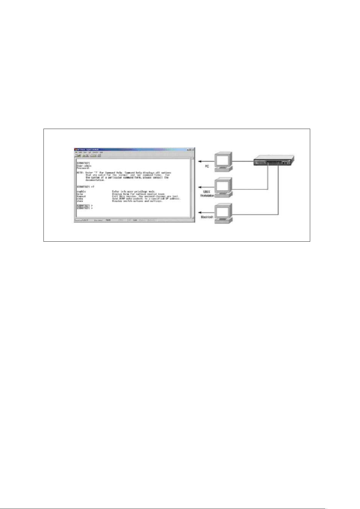
A typical console connection is illustrated below:
Figure 3-1: Console Setting Environment
- 22 -
Page 23

4.3 Set Up your Switch Using Telnet Access
Once you have set an IP address for your Switch, you can use a Telnet program (in a VT-100 compatible
terminal mode) to access and control the Switch. Most of the screens are identical, whether accessed
from the console port or from a Telnet interface.
- 23 -
Page 24
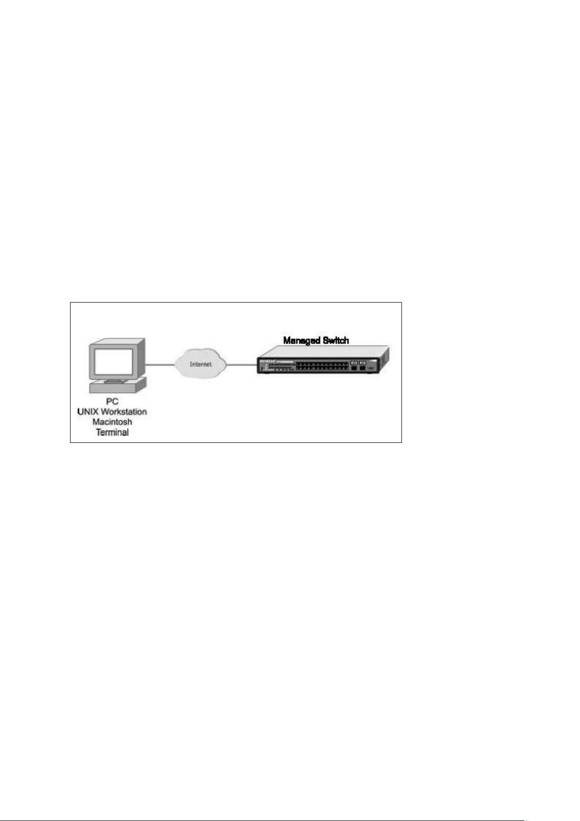
5. Web-Based Management Interface
5.1 Overview
The Fortinet FortiSwitch-548B Series Layer III plus QoS Managed Switch provides a built-in browser
interface that lets you configure and manage it remotely using a standard Web browser such as
Microsoft Internet Explorer 5.0 or later or Netscape Navigator 6.0 or later. This interface also allows for
system monitoring and management of the switch. The ‘help’ page covers many of the basic functions
and features of the switch and its Web interface. When you configure the switch for the first time from the
console, you can assign an IP address and subnet mask to the switch. Thereafter, you can access the
switch’s Web interface directly using your Web browser by entering the switch’s IP address into the
address bar. In this way, you can use your Web browser to manage the switch from a central location,
just as if you were directly connected to the switch’s console port. Below figure shows this management
method.
- 24 -
Page 25

5.2 How to log in
The Fortinet FortiSwitch-548B Series Layer III plus QoS Managed Switch can be configured remotely
from Microsoft Internet Explorer (version 5.0 or above), or Mozilla FireFox (version 3.6 or above).
1. Determine the IP address of your managed switch.
2. Open your Web browser.
3. Log in to the managed switch using the IP address the unit is currently configured with.
4. Type the default user name of admin and default of no password, or whatever password you have
set up.
Once you have entered your access point name, your Web browser automatically finds the
FortiSwitch-548B Series Layer III Managed Switch and display the home page, as shown below.
- 25 -
Page 26
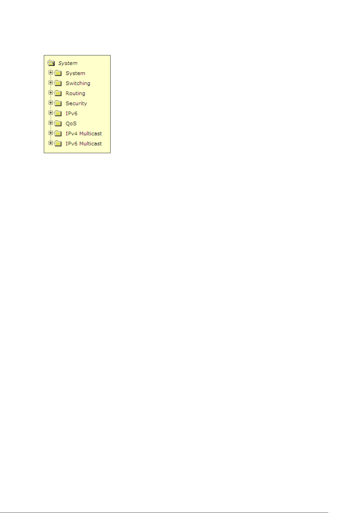
5.3 Web-Based Management Menu
Menus
The Web-based interface enables navigation through several menus. The main navigation menu is on
the left of every page and contains the screens that let you access all the commands and statistics the
switch provides.
Main Menus
System
Switching
Routing
Security
IPv6
QoS
IPv4 Multicast
IPv6 Multicast
- 26 -
Page 27
Secondary Menus
The Secondary Menus under the Main Menu contain a host of options that you can use to configure your
switch. The online help contains a detailed description of the features on each screen. You can click the
‘help’ or the question mark at the top right of each screen to view the help menu topics.
The Secondary Menus are detailed below, with cross-references to the sections in this manual that
contain the corresponding command descriptions.
System
ARP Cache — see “show arp”
Inventory — see “show hardware”
Configuration — see “Management Commands and Device Configuration Commands”
Forwarding Database — see “Device Configuration Commands’ L2MAC Address”
Logs — see “System Information and Statistics Commands”
Port — see “Device Configuration Commands’ Interface”
sFlow — see “sFlow Commands”
SNMP — see “SNMP Server Commands and SNMP Trap Commands”
Statistics — see “show interface counters”
System Utilities — see “System Utilities”
Trap Manager — see “show traplog and SNMP Trap Commands”
SNTP — see “SNTP Commands”
DHCP Client — see “DHCP Client Commands”
DNS Relay — see “Domain Name Server Relay Commands”
Switching
DHCP Snooping — see “DHCP snooping Commands”
VLAN — see “VLAN Management Commands”
Portected Port — see “Portected Port Commands”
Protocol-based VLAN — see “Protocol-based VLAN Commands”
IP Subnet-based VLAN — see “IP Subnet-based VLAN Commands”
- 27 -
Page 28

MAC-based VLAN — see “MAC-based Commands”
MAC-based Vocie VLAN — see “MAC-based Vocie VLAN Commands”
Voice VLAN — see “Voice VLAN Commands”
Filters — see “MAC Filters Commands”
GARP — see “GVRP and Bridge Extension Commands”
Dynamic Arp Inspection — see “DAI Commands”
IGMP Snooping — see “IGMP Snooping Commands”
IGMP Snooping Querier — see “IGMP Snooping Querier Commands”
MLD Snooping — see “MLD Snooping Commands”
MLD Snooping Querier — see “MLD Snooping Querier Commands”
Port Channel — see “Port Channel Commands”
Multicast Forwarding DataBase — see “L2 MAC Address and Multicast Forwarding Database Tables
Commands”
Spanning Tree — see “Spanning Tree Commands”
Class of Service — see “L2 Priority Commands”
Port Security — see “Port Security Configuration Commands”
LLDP — see “LLDP Commands”
VTP — see “VTP Commands”
Link State — see “Link state Commands”
Port Backup — see “Port backup Commands”
FIP Snooping — see “FIP Snooping Commands”
Routing
ARP — see “Address Resolution Protocol (ARP) Commands”
IP — see “IP Routing Commands”
OSPF — see “Open Shortest Path First (OSPF) Commands”
BOOTP/DHCP Relay Agent — see “BOOTP/DHCP Relay Commands”
RIP — see “Routing Information Protocol (RIP) Commands”
Router Discovery — see “Router Discovery Protocol Commands”
Router — see “IP Routing Commands”
VLAN Routing — see “VLAN Routing Commands”
VRRP — see “Virtual Router Redundancy Protocol (VRRP) Commands”
Tunnels — see “Tunnels Commands”
Loopbacks — see “Loopbacks Commands”
Security
Port Access Control — see “Dot1x Configuration Commands”
RADIUS — see “Radius Configuration Commands”
TACACS+ — see “TACACS+ Configuration Commands”
IP Filter — see “Network Commands”
- 28 -
Page 29

Secure HTTP — see “HTTP Commands”
Secure Shell — see “Secure Shell (SSH) Commands”
IPv6
OSPFv3 — see “OSPFv3 Configuration Commands”
IPv6 Routes — see “IPv6 Routes Configuration Commands”
RIPv6 — see “RIPv6 Configuration Commands”
QoS
ACL — see “ACL Commands”
Diffserv — see “Differentiated Services Commands”
Class of Service see "Class of Service Commands"
IPv4 Multicast
DVMRP — see “DVMRP Commands”
IGMP — see “IGMP Commands”
PIM-DM — see “PIM-DM Commands”
PIM-SM — see “PIM-SM Commands”
IPv6 Multicast
MLD — see “MLD Commands”
PIM-DM — see “PIM-DM Commands”
PIM-SM — see “PIM-SM Commands”
- 29 -
Page 30

6. Command Line Interface Structure and Mode-based CLI
The Command Line Interface (CLI) syntax, conventions, and terminology are described in this section.
Each CLI command is illustrated using the structure outlined below.
6.1 CLI Command Format
Commands are followed by values, parameters, or both.
Example 1
ip address <ipaddr> <netmask> [<gateway>]
ip address is the command name.
<ipaddr> <netmask> are the required values for the command.
[<gateway>] is the optional value for the command.
Example 2
snmp-server location <loc>
snmp-server location is the command name.
<loc> is the required parameter for the command.
Example 3
clear vlan
clear vlan is the command name.
Command
The text in bold, non-italic font must be typed exactly as shown.
- 30 -
Page 31

6.2 CLI Mode-based Topology
Parameters
Parameters are order dependent.
The text in bold italics should be replaced with a name or number. To use spaces as part of a
name parameter, enclose it in double quotes like this: "System Name with Spaces".
Parameters may be mandatory values, optional values, choices, or a combination.
<parameter>. The <> angle brackets indicate that a mandatory parameter must be entered in
place of the brackets and text inside them.
[parameter]. The [] square brackets indicate that an optional parameter may be entered in place
of the brackets and text inside them.
choice1 | choice2. The | indicates that only one of the parameters should be entered.
The {} curly braces indicate that a parameter must be chosen from
the list of choices.
Values
ipaddr This parameter is a valid IP address, made up of four decimal bytes ranging from 0 to 255.
The default for all IP parameters consists of zeros (that is, 0.0.0.0). The interface IP address of 0.0.0.0 is
invalid.
macaddr The MAC address format is six hexadecimal numbers separated by colons, for example
00:06:29:32:81:40.
areaid Area IDs may be entered in dotted-decimal notation (for example, 0.0.0.1). An area ID of
0.0.0.0 is reserved for the backbone. Area IDs have the same form as IP addresses, but are distinct from
IP addresses. The IP network number of the sub-netted network may be used for the area ID.
routerid The value of <router id> must be entered in 4-digit dotted-decimal notation (for
example, 0.0.0.1). A router ID of 0.0.0.0 is invalid.
slot/port This parameter denotes a valid slot number, and a valid port number. For example, 0/1
represents unit number 1, slot number 0 and port number 1. The <slot/port> field is composed of a valid
slot number and a valid port number separated by a forward slash (/).
logical slot/port This parameter denotes a logical slot number, and logical port number
assigned. This is applicable in the case of a port-channel (LAG). The operator can use the
logical slot number, and the logical port number to configure the port-channel.
- 31 -
Page 32

Address Type
Format
Range
IPAddr
A.B.C.D
0.0.0.0 to 255.255.255.255
MacAddr
YY:YY:YY:YY:YY:YY
hexidecimal digit pairs
Conventions
Network addresses are used to define a link to a remote host, workstation, or network. Network
addresses are shown using the following syntax:
Table 5-1. Network Address Syntax
Double quotation marks such as "System Name with Spaces" set off user defined strings. If the operator
wishes to use spaces as part of a name parameter then it must be enclosed in double quotation marks.
Empty strings (““) are not valid user defined strings. Command completion finishes spelling the
command when enough letters of a command are typed to uniquely identify the command word. The
command may be executed by typing <enter> (command abbreviation) or the command word may be
completed by typing the <tab> or <space bar> (command completion).
The value 'Err' designates that the requested value was not internally accessible. This should never
happen and indicates that there is a case in the software that is not handled correctly.
The value of '-----' designates that the value is unknown.
Annotations
The CLI allows the user to type single-line annotations at the command prompt for use when writing test
or configuration scripts and for better readability. The exclamation point (‘!’) character flags the beginning
of a comment. The comment flag character can begin a word anywhere on the command line and all
input following this character is ignored. Any command line that begins with the character ‘!’ is
recognized as a comment line and ignored by the parser.
Some examples are provided below:
! Script file for displaying the ip interface
! Display information about interfaces
show ip interface 0/1 !Displays the information about the first interface
! Display information about the next interface
show ip interface 0/2
! End of the script file
- 32 -
Page 33

Syntax
show arp
Syntax
show calendar
7. Switching Commands
7.1 System Information and Statistics commands
7.1.1 show arp
This command displays connectivity between the switch and other devices. The Address Resolution
Protocol (ARP) cache identifies the MAC addresses of the IP stations communicating with the switch.
Default Setting
None
Command Mode
Privileged Exec
Display Message
MAC Address: A unicast MAC address for which the switch has forwarding and/or filtering
information. The format is 6 two-digit hexadecimal numbers that are separated by colons. For
example: 00:23:45:67:89:AB
IP Address: The IP address assigned to each interface.
Interface: Valid slot number and a valid port number.
7.1.2 show calendar
This command displays the system time.
Default Setting
None
Command Mode
Privileged Exec
Display Message
Current Time displays system time
- 33 -
Page 34

Syntax
show process cpu
i
It is not necessarily the traffic to the CPU, but different tasks that keep the CPU busy.
7.1.3 show process cpu
This command provides the percentage utilization of the CPU by different tasks.
Default Setting
None
Command Mode
Privileged Exec
Display Message
The following shows example CLI display output for the command.
Memory Utilization Report
status bytes
------ ---------free 192980480
alloc 53409968
Task Utilization Report
Task Utilization
----------------------- ----------bcmL2X.0 0.75%
bcmCNTR.0 0.20%
bcmLINK.0 0.35%
DHCP snoop 0.10%
Dynamic ARP Inspection 0.10%
dot1s_timer_task 0.10%
dhcpsPingTask 0.20%
- 34 -
Page 35

Syntax
show eventlog [unit]
Syntax
show running-config [all | <scriptname>]
7.1.4 show eventlog
This command displays the event log, which contains error messages from the system, in the Primary
Management System or in the specified unit. The event log is not cleared on a system reset.
unit - The unit number of the remote system. The range is 1 to 8.
Default Setting
None
Command Mode
Privileged Exec
Display Message
File: The file in which the event originated.
Line: The line number of the event.
Task Id: The task ID of the event.
Code: The event code.
Time: The time this event occurred.
Note: Event log information is retained across a switch reset.
7.1.5 show running-config
This command is used to display/capture the current setting of different protocol packages supported on
switch. This command displays/captures only commands with settings/configurations with values that
differ from the default value. The output is displayed in script format, which can be used to configure
another switch with the same configuration.
When a script name is provided, the output is redirected to a configuration script. The option [all] will also
enable the display/capture of all commands with settings/configurations that include values that are
same as the default values. If the optional <scriptname> is provided with a file name extension of “.scr”,
the output will be redirected to a script file.
all - enable the display/capture of all commands with settings/configurations that include values that
are same as the default values.
<scriptname> - redirect the output to the file <scriptname>.
- 35 -
Page 36

Syntax
show sysinfo
Syntax
show system
Default Setting
None
Command Mode
Privileged Exec
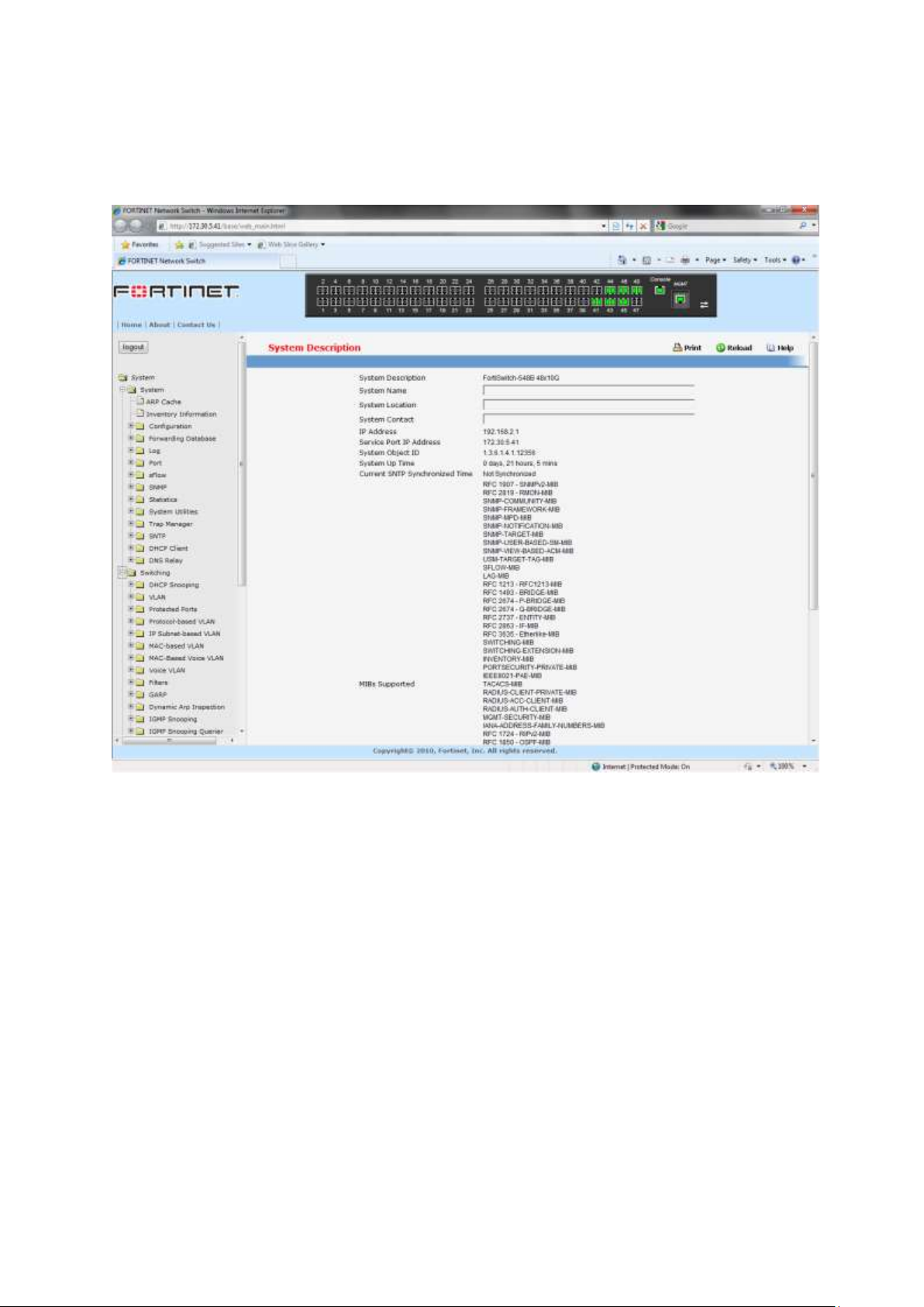
7.1.6 show sysinfo
This command displays switch brief information and MIBs supported.
Default Setting
None
Command Mode
Privileged Exec
Display Message
System Description: The text used to identify this switch.
System Name: The name used to identify the switch.
System Location: The text used to identify the location of the switch. May be up to 31
alpha-numeric characters. The factory default is blank.
System Contact: The text used to identify a contact person for this switch. May be up to 31
alphanumeric characters. The factory default is blank.
System Object ID: The manufacturing ID.
System Up Time: The time in days, hours and minutes since the last switch reboot.
Current SNTP Syncronized Time: The time which is synchronized from SNTP server.
MIBs Supported: A list of MIBs supported by this agent.
7.1.7 show system
This command displays switch system information.
Default Setting
None
Command Mode
Privileged Exec
- 36 -
Page 37

Syntax
show tech-support
Syntax
show hardware
Display Message
System Description: Text used to identify this switch.
System Object ID: The manufacturing ID
System Information
System Up Time: The time in days, hours and minutes since the last switch reboot.
System Name: Name used to identify the switch.
System Location: Text used to identify the location of the switch. May be up to 31 alpha-numeric
characters. The factory default is blank.
System Contact: Text used to identify a contact person for this switch. May be up to 31
alphanumeric characters. The factory default is blank.
MAC Address: The burned in MAC address used for in-band connectivity.
Web Server: Displays to enable/disable web server function
Web Server Port: Displays the web server http port
Web Server Java Mode: Specifies if the switch should allow access to the Java applet in the header
frame. Enabled means the applet can be viewed. The factory default is disabled.
Protocol Current: Indicates which network protocol is being used. The options are bootp | dhcp |
none.
DHCP Client Identifier TEXT: DCHP client identifier for this switch.
7.1.8 show tech-support
This command displays system and configuration information when you contact technical support. The
output of the show tech-support command combines the output of the following commands: show
version, show sysinfo, show port all, show logging, show event log, • show logging buffered,
show trap log, show running config.
Default Setting
None
Command Mode
Privileged Exec
7.1.9 show hardware
This command displays inventory information for the switch.
- 37 -
Page 38

Default Setting
None
Command Mode
Privileged Exec
Display Message
System Description: Text used to identify the product name of this switch.
Machine Type: Specifies the machine model as defined by the Vital Product Data.
Machine Model: Specifies the machine model as defined by the Vital Product Data.
Serial Number: The unique box serial number for this switch.
Label Revision Number: The label revision serial number of this switch is used for manufacturing
purposes.
Part Number: Manufacturing part number.
Hardware Version: The hardware version of this switch. It is divided into four parts. The first byte is
the major version and the second byte represents the minor version.
Loader Version: The release version maintenance number of the loader code currently running on
the switch. For example, if the release was 1, the version was 2, and the maintenance number was
4, the format would be '1.2.4'.
Boot Rom Version: The release version maintenance number of the boot ROM code currently
running on the switch. For example, if the release was 1, the version was 2, and the maintenance
number was 4, the format would be '1.2.4'.
Operating Code Version: The release version maintenance number of the code currently running
on the switch. For example, if the release was 1, the version was 2, and the maintenance number
was 4, the format would be '1.2.4'.
ADT7460_1: Now Temperature: The temperature of sensor of ADT7460 1.
ADT7460_2: Now Temperature: The temperature of sensor of ADT7460 2.
Depend on air flow FAN 1 – 4 connected ADT7460-1 or ADT7460-2:
Front-To-Back: (Connected ADT7460-1)
ADT7460_1: Fan 1 Status: Status of Fan1. It could be active or inactive.
ADT7460_1: Fan 2 Status: Status of Fan2. It could be active or inactive.
ADT7460_1: Fan 3 Status: Status of Fan3. It could be active or inactive.
ADT7460_1: Fan 4 Status: Status of Fan3. It could be active or inactive.
Back-To-Front: (Connected ADT7460-2)
ADT7460_2: Fan 1 Status: Status of Fan1. It could be active or inactive.
ADT7460_2: Fan 2 Status: Status of Fan2. It could be active or inactive.
ADT7460_2: Fan 3 Status: Status of Fan3. It could be active or inactive.
ADT7460_2: Fan 4 Status: Status of Fan3. It could be active or inactive.
Switch Power+ y……………… Power Supply (The yth power supply information of switch 1).
- 38 -
Page 39

!
Below 10-Giga Interface information depend on plugging SFP+ Transceiver
Syntax
show version
Name: Name provided by Power Supply vendor.
Model: Model Number provided by Power Supply vendor.
Revision Number: Revision Number provided by Power Supply vendor.
Manufacturer Location: Location provided by Power Supply vendor.
Date of Manufacturing: Date of Manufacturing provided by Power Supply vendor.
Serial Numbe: Serial Number provided by Power Supply vendor.
Temperature 1:. Inner temperature 1 of Power Supply now
Temperature 2: Inner temperature 2 of Power Supply now
Fan Speed: Inner fan speed(rpm) of Power Supply now
Fan Duty: Inner fan duty(%) of Power Supply now
Interface = y...................... SFP+(The yth 10-Giga information of switch 1).
10 Gigabit Ethernet Compliance Codes: Transceiver’s compliance codes.
Vendor Name: The SFP transceiver vendor name shall be the full name of the corporation, a
commonly accepted abbreviation of the name of the corporation, the SCSI company code for the
corporation, or the stock exchange code for the corporation.
Vendor Part Number: Part number provided by SFP transceiver vendor.
Vendor Serial Number: Serial number provided by vendor.
Vendor Revision Number: Revision level for part number provided by vendor.
Vendor Manufacturing Date: The vendor’s manufacturing date.
Additional Packages: This displays the additional packages that are incorporated into this system.
7.1.10 show version
This command displays inventory information for the switch.
Default Setting
None
Command Mode
Privileged Exec
Display Message
- 39 -
Page 40

Syntax
show loginsession
Serial Number: The unique box serial number for this switch.
Hardware Version: The hardware version of this switch. It is divided into four parts. The first byte is
the major version and the second byte represents the minor version.
Number of ports:Total number of port for this swirch system.
Label Revision Number: The label revision serial number of this switch is used for manufacturing
purposes.
Part Number: Manufacturing part number.
Machine Model: Specifies the machine model as defined by the Vital Product Data.
Loader Version: The release version maintenance number of the loader code currently running on
the switch. For example, if the release was 1, the version was 2, and the maintenance number was
4, the format would be '1.2.4'.
Operating Code Version: The release version maintenance number of the code currently running
on the switch. For example, if the release was 1, the version was 2, and the maintenance number
was 4, the format would be '1.2.4'.
Boot Rom Version: The release version maintenance number of the boot ROM code currently
running on the switch. For example, if the release was 1, the version was 2, and the maintenance
number was 4, the format would be '1.2.4'.
7.1.11 show loginsession
This command displays current telnet and serial port connections to the switch.
Default Setting
None
Command Mode
Privileged Exec
Display Message
ID: Login Session ID
User Name: The name the user will use to login using the serial port or Telnet. A new user may be
added to the switch by entering a name in a blank entry. The user name may be up to 8 characters,
and is not case sensitive. Two users are included as the factory default, admin, and guest.
Connection From: IP address of the telnet client machine or EIA-232 for the serial port connection.
- 40 -
Idle Time: Time this session has been idle.
Session Time: Total time this session has been connected.
Session Type: Shows the type of session: telnet, serial or SSH.
Page 41

Syntax
show command [| begin/include/exclude <LINE>]
Syntax
show interface status {<slot/port> | all}
7.1.12 show command filter
This command displays the information that begin/include/exclude the regular expression.
Default Setting
None
Command Mode
Privileged Exec
Display Message
command: Any show command of the CLI
begin: Begin with the line that matches
include: Include lines that match
exclude: Exclude lines that match
<LINE>: Regular Expression
7.2 Device Configuration Commands
7.2.1 Interface
7.2.1.1 show interface status
This command displays the Port monitoring information for the system.
<slot/port> - is the desired interface number.
all - This parameter displays information for all interfaces.
Default Setting
None
Command Mode
Privileged Exec
Display Message
Intf: The physical slot and physical port.
Type: If not blank, this field indicates that this port is a special type of port. The possible values are:
- 41 -
Page 42

Syntax
show interface counters {<slot/port> | all}
Source: This port is a monitoring port.
PC Mbr: This port is a member of a port-channel (LAG).
Dest: This port is a probe port.
Admin Mode: Selects the Port control administration state. The port must be enabled in order for it
to be allowed into the network. It may be enabled or disabled. The factory default is enabled.
Physical Mode: Selects the desired port speed and duplex mode. If auto-negotiation support is
selected, then the duplex mode and speed will be set from the auto-negotiation process. Note that
the port's maximum capability (full duplex 100M) will be advertised. Otherwise, this object will
determine the port's duplex mode and transmission rate. The factory default is Auto.
Physical Status: Indicates the port speed and duplex mode.
Link Status: Indicates whether the Link is up or down.
Link Trap: This object determines whether to send a trap when link status changes. The factory
default is enabled.
LACP Mode: Displays whether LACP is enabled or disabled on this port.
Flow Control Mode: Displays flow control mode. The possible values are:
None: This port is disabled flow control.
802.3X: This port is enabled flow control.
PFC: This port is enable Priority Flow control.
Capabilities Status: Displays interface capabilities.
7.2.1.2 show interface counters
This command displays a summary of statistics for a specific interface or all interfaces.
<slot/port> - is the desired interface number.
all - This command displays statistics information for all interfaces.
Default Setting
None
Command Mode
Privileged Exec
Display Message
The display parameters when the argument is '<slot/port>' are as follows:
Packets Received Without Error: The total number of packets (including broadcast packets and
multicast packets) received by the processor.
Packets Received With Error: The number of inbound packets that contained errors preventing
them from being deliverable to a higher-layer protocol.
- 42 -
Page 43

Syntax
show interface counters detailed {<slot/port> | switchport}
Broadcast Packets Received: The total number of packets received that were directed to the
broadcast address. Note that this does not include multicast packets.
Packets Transmitted Without Error: The total number of packets transmitted out of the interface.
Transmit Packets Errors: The number of outbound packets that could not be transmitted because
of errors.
Collisions Frames: The best estimate of the total number of collisions on this Ethernet segment.
Time Since Counters Last Cleared: The elapsed time, in days, hours, minutes, and seconds since
the statistics for this port were last cleared.
The display parameters when the argument is 'all' are as follows:
Interface: The physical slot and physical port or the logical slot and logical port.
Summary: The summation of the statistics of all ports.
Packets Received Without Error: The total number of packets (including broadcast packets and
multicast packets) received.
Packets Received With Error: The number of inbound packets that contained errors preventing
them from being deliverable to a higher-layer protocol.
Broadcast Packets Received: The total number of packets received that were directed to the
broadcast address. Note that this does not include multicast packets.
Packets Transmitted Without Error: The total number of packets transmitted.
Transmit Packets Errors: The number of outbound packets that could not be transmitted because
of errors.
Collisions Frames: The best estimate of the total number of collisions on this Ethernet segment.
This command displays detailed statistics for a specific port or for all CPU traffic based upon the
argument.
<slot/port> - is the desired interface number.
switchport - This parameter specifies whole switch or all interfaces.
Default Setting
None
Command Mode
Privileged Exec
Display Message
The display parameters when the argument is ' <slot/port>' are as follows:
- 43 -
Page 44

Total Packets Received (Octets): The total number of octets of data (including those in bad
packets) received on the network (excluding framing bits but including FCS octets). This object can
be used as a reasonable estimate of Ethernet utilization. If greater precision is desired, the
etherStatsPkts and etherStatsOctets objects should be sampled before and after a common interval.
The result of this equation is the value Utilization which is the percent utilization of the Ethernet
segment on a scale of 0 to 100 percent.
Packets Received 64 Octets: The total number of packets (including bad packets) received that
were 64 octets in length (excluding framing bits but including FCS octets).
Packets Received 65-127 Octets: The total number of packets (including bad packets) received
that were between 65 and 127 octets in length inclusive (excluding framing bits but including FCS
octets).
Packets Received 128-255 Octets: The total number of packets (including bad packets) received
that were between 128 and 255 octets in length inclusive (excluding framing bits but including FCS
octets).
Packets Received 256-511 Octets: The total number of packets (including bad packets) received
that were between 256 and 511 octets in length inclusive (excluding framing bits but including FCS
octets).
Packets Received 512-1023 Octets: The total number of packets (including bad packets) received
that were between 512 and 1023 octets in length inclusive (excluding framing bits but including FCS
octets).
Packets Received 1024-1518 Octets: The total number of packets (including bad packets) received
that were between 1024 and 1518 octets in length inclusive (excluding framing bits but including
FCS octets).
Packets Received > 1522 Octets: The total number of packets received that were longer than 1522
octets (excluding framing bits, but including FCS octets) and were otherwise well formed.
Packets RX and TX 64 Octets: The total number of packets (including bad packets) received that
were 64 octets in length (excluding framing bits but including FCS octets).
Packets RX and TX 65-127 Octets: The total number of packets (including bad packets) received
that were between 65 and 127 octets in length inclusive (excluding framing bits but including FCS
octets).
Packets RX and TX 128-255 Octets: The total number of packets (including bad packets) received
that were between 128 and 255 octets in length inclusive (excluding framing bits but including FCS
octets).
Packets RX and TX 256-511 Octets: The total number of packets (including bad packets) received
that were between 256 and 511 octets in length inclusive (excluding framing bits but including FCS
octets).
Packets RX and TX 512-1023 Octets: The total number of packets (including bad packets) received
that were between 512 and 1023 octets in length inclusive (excluding framing bits but including FCS
octets).
Packets RX and TX 1024-1518 Octets: The total number of packets (including bad packets)
received that were between 1024 and 1518 octets in length inclusive (excluding framing bits but
including FCS octets).
Packets RX and TX 1519-1522 Octets: The total number of packets (including bad packets)
received that were between 1519 and 1522 octets in length inclusive (excluding framing bits but
including FCS octets).
Packets RX and TX 1523-2047 Octets: The total number of packets (including bad packets)
received that were between 1523 and 2047 octets in length inclusive (excluding framing bits but
including FCS octets).
- 44 -
Page 45

Packets RX and TX 2048-4095 Octets: The total number of packets (including bad packets)
received that were between 2048 and 4095 octets in length inclusive (excluding framing bits but
including FCS octets).
Packets RX and TX 4096-9216 Octets: The total number of packets (including bad packets)
received that were between 4096 and 9216 octets in length inclusive (excluding framing bits but
including FCS octets).
Total Packets Received Without Errors
Unicast Packets Received: The number of subnetwork-unicast packets delivered to a higher-layer
protocol.
Multicast Packets Received: The total number of good packets received that were directed to a
multicast address. Note that this number does not include packets directed to the broadcast address.
Broadcast Packets Received: The total number of good packets received that were directed to the
broadcast address. Note that this does not include multicast packets.
Total Packets Received with MAC Errors
Jabbers Received: The total number of packets received that were longer than 1518 octets
(excluding framing bits, but including FCS octets), and had either a bad FCS with an integral number
of octets (FCS Error) or a bad FCS with a non-integral number of octets (Alignment Error). Note that
this definition of jabber is different than the definition in IEEE-802.3 section 8.2.1.5 (10BASE5) and
section 10.3.1.4 (10BASE2). These documents define jabber as the condition where any packet
exceeds 20 ms. The allowed range to detect jabber is between 20 ms and 150 ms.
Undersize Received: The total number of packets received that were less than 64 octets in length
with GOOD CRC(excluding framing bits but including FCS octets).
Fragments Received: The total number of packets received that were less than 64 octets in length
with ERROR CRC(excluding framing bits but including FCS octets).
Alignment Errors: The total number of packets received that had a length (excluding framing bits,
but including FCS octets) of between 64 and 1518 octets, inclusive, but had a bad FCS with a
non-integral number of octets.
FCS Errors: The total number of packets received that had a length (excluding framing bits, but
including FCS octets) of between 64 and 1518 octets, inclusive, but had a bad FCS with an integral
number of octets
Overruns: The total number of frames discarded as this port was overloaded with incoming packets,
and could not keep up with the inflow.
Total Packets Transmitted (Octets)
Packets Transmitted 64 Octets: The total number of packets (including bad packets) received that
were 64 octets in length (excluding framing bits but including FCS octets).
Packets Transmitted 65-127 Octets: The total number of packets (including bad packets) received
that were between 65 and 127 octets in length inclusive (excluding framing bits but including FCS
octets).
Packets Transmitted 128-255 Octets: The total number of packets (including bad packets)
received that were between 128 and 255 octets in length inclusive (excluding framing bits but
including FCS octets).
Packets Transmitted 256-511 Octets: The total number of packets (including bad packets)
received that were between 256 and 511 octets in length inclusive (excluding framing bits but
including FCS octets).
- 45 -
Page 46

Packets Transmitted 512-1023 Octets: The total number of packets (including bad packets)
received that were between 512 and 1023 octets in length inclusive (excluding framing bits but
including FCS octets).
Packets Transmitted 1024-1518 Octets: The total number of packets (including bad packets)
received that were between 1024 and 1518 octets in length inclusive (excluding framing bits but
including FCS octets).
Packets Transmitted 1519-1522 Octets: The total number of packets (including bad packets)
received that were between 1519 and 1522 octets in length inclusive (excluding framing bits but
including FCS octets).
Max Info: The maximum size of the Info (non-MAC) field that this port will receive or transmit.
Total Packets Transmitted Successfully
Unicast Packets Transmitted: The total number of packets that higher-level protocols requested be
transmitted to a subnetwork-unicast address, including those that were discarded or not sent.
Multicast Packets Transmitted: The total number of packets that higher-level protocols requested
be transmitted to a Multicast address, including those that were discarded or not sent.
Broadcast Packets Transmitted: The total number of packets that higher-level protocols requested
be transmitted to the Broadcast address, including those that were discarded or not sent.
Total Transmit Errors
FCS Errors: The total number of packets transmitted that had a length (excluding framing bits, but
including FCS octets) of between 64 and 1518 octets, inclusive, but had a bad FCS with an integral
number of octets
Tx Oversized: The total number of frames that exceeded the max permitted frame size. This
counter has a max increment rate of 815 counts per sec. at 10 Mb/s.
Underrun Errors: The total number of frames discarded because the transmit FIFO buffer became
empty during frame transmission.
Total Transmited Packets Discards
Single Collision Frames: A count of the number of successfully transmitted frames on a particular
interface for which transmission is inhibited by exactly one collision.
Multiple Collision Frames: A count of the number of successfully transmitted frames on a particular
interface for which transmission is inhibited by more than one collision.
Excessive Collisions: A count of frames for which transmission on a particular interface fails due to
excessive collisions.
GVRP PDUs Received: The count of GVRP PDUs received in the GARP layer.
GVRP PDUs Transmitted: The count of GVRP PDUs transmitted from the GARP layer.
GVRP Failed and Registrations: The number of times attempted GVRP registrations could not be
completed.
GMRP PDUs received: The count of GMRP PDUs received in the GARP layer.
GMRP PDUs Transmitted: The count of GMRP PDUs transmitted from the GARP layer.
GMRP Failed Registrations: The number of times attempted GMRP registrations could not be
completed.
STP BPDUs Transmitted: Spanning Tree Protocol Bridge Protocol Data Units sent.
- 46 -
Page 47

STP BPDUs Received: Spanning Tree Protocol Bridge Protocol Data Units received.
RSTP BPDUs Transmitted: Rapid Spanning Tree Protocol Bridge Protocol Data Units sent.
RSTP BPDUs Received: Rapid Spanning Tree Protocol Bridge Protocol Data Units received.
MSTP BPDUs Transmitted: Multiple Spanning Tree Protocol Bridge Protocol Data Units sent.
MSTP BPDUs Received: Multiple Spanning Tree Protocol Bridge Protocol Data Units received.
EAPOL Frames Received: The number of valid EAPOL frames of any type that have been received
by this authenticator.
EAPOL Frames Transmitted: The number of EAPOL frames of any type that have been
transmitted by this authenticator.
Time Since Counters Last Cleared: The elapsed time, in days, hours, minutes, and seconds since
the statistics for this port were last cleared.
The display parameters when the argument is ‘switchport’ are as follows:
Total Packets Received (Octets): The total number of octets of data received by the processor
(excluding framing bits but including FCS octets).
Packets Received Without Error: The total number of packets (including broadcast packets and
multicast packets) received by the processor.
Unicast Packets Received: The number of subnetwork-unicast packets delivered to a higher-layer
protocol.
Multicast Packets Received: The total number of packets received that were directed to a multicast
address. Note that this number does not include packets directed to the broadcast address.
Broadcast Packets Received: The total number of packets received that were directed to the
broadcast address. Note that this does not include multicast packets.
Receive Packets Discarded: The number of inbound packets which were chosen to be discarded
even though no errors had been detected to prevent their being deliverable to a higher-layer
protocol. A possible reason for discarding a packet could be to free up buffer space.
Octets Transmitted: The total number of octets transmitted out of the interface, including framing
characters.
Packets Transmitted without Errors: The total number of packets transmitted out of the interface.
Unicast Packets Transmitted: The total number of packets that higher-level protocols requested be
transmitted to a subnetwork-unicast address, including those that were discarded or not sent.
Multicast Packets Transmitted: The total number of packets that higher-level protocols requested
be transmitted to a Multicast address, including those that were discarded or not sent.
Broadcast Packets Transmitted: The total number of packets that higher-level protocols requested
be transmitted to the Broadcast address, including those that were discarded or not sent.
Transmit Packets Discarded: The number of outbound packets which were chosen to be
discarded even though no errors had been detected to prevent their being deliverable to a
higher-layer protocol. A possible reason for discarding a packet could be to free up buffer space.
Most Address Entries Ever Used: The highest number of Forwarding Database Address Table
entries that have been learned by this switch since the most recent reboot.
Address Entries Currently in Use: The number of Learned and static entries in the Forwarding
Database Address Table for this switch.
- 47 -
Page 48

Syntax
show interface switch
Maximum VLAN Entries: The maximum number of Virtual LANs (VLANs) allowed on this switch.
Most VLAN Entries Ever Used: The largest number of VLANs that have been active on this switch
since the last reboot.
Static VLAN Entries: The number of presently active VLAN entries on this switch that have been
created statically.
Dynamic VLAN Entries: The number of presently active VLAN entries on this switch that have been
created by GVRP registration.
VLAN Deletes: The number of VLANs on this switch that have been created and then deleted since
the last reboot.
Time Since Counters Last Cleared: The elapsed time, in days, hours, minutes, and seconds, since
the statistics for this switch were last cleared.
7.2.1.3 show interface switch
This command displays a summary of statistics for all CPU traffic.
Default Setting
None
Command Mode
Privileged Exec
Display Message
Broadcast Packets Received: The total number of packets received that were directed to the
broadcast address. Note that this does not include multicast packets.
Packets Received With Error: The number of inbound packets that contained errors preventing
them from being deliverable to a higher-layer protocol.
Packets Transmitted Without Error: The total number of packets transmitted out of the interface.
Broadcast Packets Transmitted: The total number of packets that higher-level protocols requested
to be transmitted to the Broadcast address, including those that were discarded or not sent.
Transmit Packet Errors: The number of outbound packets that could not be transmitted because of
errors.
Address Entries Currently In Use: The total number of Forwarding Database Address Table
entries now active on the switch, including learned and static entries.
VLAN Entries Currently In Use: The number of VLAN entries presently occupying the VLAN table.
Time Since Counters Last Cleared: The elapsed time, in days, hours, minutes, and seconds since
the statistics for this switch were last cleared.
- 48 -
Page 49

Syntax
interface <slot/port>
i
The 10-Giga interfaces will not provide the following command. Instead, it provides a
command to set the speed of 10-Giga port to 1Gbps. Use ‘speed-duplex 1000’ to change the
speed of 10-Giga port to 1G speed.
Syntax
speed-duplex 1000
no speed-duplex 1000
Syntax
speed-duplex all 1000
no speed-duplex all 1000
7.2.1.4 interface
This command is used to enter Interface configuration mode.
<slot/port> - is the desired interface number.
Default Setting
None
Command Mode
Global Config
7.2.1.5 speed-duplex
This command is used to set the speed and duplex mode for the interface.
1000 – 1000 Mbps, only valid for 10G ports.
no - This command will be back to 10G speed from 1G speed on a port.
Default Setting
None
Command Mode
Interface Config
This command is used to set the speed and duplex mode for all interfaces.
1000 – 1000 Mbps, only valid for 10G ports.
- 49 -
Page 50

i
The 10-Giga interfaces will not provide the following command.
Syntax
negotiate
no negotiate
Syntax
negotiate all
no negotiate all
all - This command represents all interfaces.
no - This command will be back to 10G speed from 1G speed for all ports.
Default Setting
None
Command Mode
Global Config
7.2.1.6 negotiate
This command enables automatic negotiation on a port. The default value is enabled.
no - This command disables automatic negotiation on a port.
Default Setting
Enable
Command Mode
Interface Config
This command enables automatic negotiation on all interfaces. The default value is enabled.
all - This command represents all interfaces.
no - This command disables automatic negotiation on all interfaces.
Default Setting
Enable
- 50 -
Page 51

i
The 10-Giga interfaces will not provide the following command.
Syntax
capabilities {{10 | 100 } {full-duplex | half-duplex}} | {1000 full-duplex }
no capabilities {{10 | 100 } {full-duplex | half-duplex}} | {1000 full-duplex }
Syntax
capabilities all {{10 | 100} {full-duplex | half-duplex}} | {1000 full-duplex }
no capabilities all {{10 | 100} {full-duplex | half-duplex}} | {1000 full-duplex }
Command Mode
Global Config
7.2.1.7 capabilities
This command is used to set the capabilities on specific interface.
10 - 10BASE-T
100 - 100BASE-T
1000 - 1000BASE-T
full-duplex - Full duplex
half-duplex - Half duplex
no - This command removes the advertised capability with using parameter.
Default Setting
10 half-duplex, 10 full-duplex, 100 half-duplex, 100 full-duplex, and 1000 full-duplex
Command Mode
Interface Config
This command is used to set the capabilities on all interfaces.
10 - 10BASE-T
100 - 100BASE-T
1000 - 1000BASE-T
full-duplex - Full duplex
half-duplex - Half duplex
all - This command represents all interfaces.
no - This command removes the advertised capability with using parameter
- 51 -
Page 52

i
802.3x flow control only applies to full-duplex mode ports.
Syntax
storm-control flowcontrol
no storm-control flowcontrol
i
802.3x flow control only applies to full-duplex mode ports.
Syntax
storm-control flowcontrol
no storm-control flowcontrol
Default Setting
10 half-duplex, 10 full-duplex, 100 half-duplex, 100 full-duplex, and 1000 full-duplex
Command Mode
Global Config
7.2.1.8 storm-control flowcontrol
This command enables 802.3x flow control for the switch.
no - This command disables 802.3x flow control for the switch.
Default Setting
Disabled
Command Mode
Global Config
This command enables 802.3x flow control for the specific interface.
no - This command disables 802.3x flow control for the specific interface.
Default Setting
Disabled
Command Mode
Interface Config
- 52 -
Page 53

i
802.3x flow control only applies to full-duplex mode ports.
Syntax
storm-control flowcontrol pfc
no storm-control flowcontrol pfc
Syntax
shutdown
no shutdown
Syntax
shutdown all
no shutdown all
7.2.1.9 storm-control flowcontrol pfc
The PFC function is disabled by default. Only after enabling it, the PFC process also starts.
Once the feature is enabled, the original basic IEEE 802.3x PAUSE control cannot be enabled.
It means these two features cannot be enabled at the same time.
no - This command disables Priority Flow Control for the specific interface.
Default Setting
Disabled
Command Mode
Interface Config
7.2.1.10 shutdown
This command is used to disable a port.
no - This command enables a port.
Default Setting
Enabled
Command Mode
Interface Config
This command is used to disable all ports.
- 53 -
Page 54

Syntax
description <description>
no description
i
The 10-Giga interface will not provide the following command.
Syntax
mdi {auto|across|normal}
no mdi
all - This command represents all ports.
no - This command enables all ports.
Default Setting
Enabled
Command Mode
Global Config
7.2.1.11 description
This command is used to create an alpha-numeric description of the port.
no - This command removes the description of the port.
Default Setting
None
Command Mode
Interface Config
7.2.1.12 mdi
This command is used to configure the physical port MDI/MDIX state.
auto - This type is auto selecting cable type.
across - This type is only allowed the Across-over cable.
normal - This type is only allowed the Normal cable.
no - This command restore the port mode to Auto.
- 54 -
Page 55

Syntax
show mac-addr-table [{<macaddr> <vlanid> |all}]
Default Setting
Auto
Command Mode
Interface Config
7.2.2 L2 MAC Address and Multicast Forwarding Database Tables
7.2.2.1 show mac-addr-table
This command displays the forwarding database entries. If the command is entered with no parameter,
the entire table is displayed. This is the same as entering the optional all parameter. Alternatively, the
administrator can enter a MAC Address to display the table entry for the requested MAC address and all
entries following the requested MAC address.
<macaddr> - enter a MAC Address to display the table entry for the requested MAC address.
<vlanid> - VLAN ID (Range: 1 – 3965)
all – this command displays the entire table.
Default Setting
None
Command Mode
Privileged Exec
Display Message
Mac Address: A unicast MAC address for which the switch has forwarding and/or filtering
information. The format is 6 or 8 two-digit hexadecimal numbers that are separated by colons, for
example 01:23:45:67:89:AB. In an IVL system the MAC address will be displayed as 8 bytes. In an
SVL system, the MAC address will be displayed as 6 bytes. Note: This software version only
supports IVL systems.
Interface: The port on which this L2 MAC address was learned.
if Index: This object indicates the if Index of the interface table entry associated with this port.
Status: The status of this entry.
The meanings of the values are:
Static: The value of the corresponding instance was added by the system or a user when a static
MAC filter was defined. It cannot be relearned.
Learned: The value of the corresponding instance was learned by observing the source MAC
addresses of incoming traffic, and is currently in use.
Management: The value of the corresponding instance (system MAC address) is also the value
of an existing instance of dot1dStaticAddress. It is identified with interface 3/1 and is currently
used when enabling VLANs for routing.
- 55 -
Page 56

Syntax
show mac-addr-table count
Syntax
show mac-addr-table interface <slot/port>
Self: The value of the corresponding instance is the address of one of the switch’s physical
interfaces (the system’s own MAC address).
GMRP Learned: The value of the corresponding instance was learned via GMRP and applies to
Multicast.
Other: The value of the corresponding instance does not fall into one of the other categories.
7.2.2.2 show mac-addr-table count
This command displays the total forwarding database entries, the number of static and learnning mac
address, and the max address available on the switch.
Default Setting
None
Command Mode
Privileged Exec
Display Message
Dynamic Address count: The total learning mac addresses on the L2 MAC address Table.
Static Address (User-defined) count: The total user-defined addresses on the L2 MAC address
Table.
Total MAC Addresses in use: This number of addresses are used on the L2 MAC address table.
Total MAC Addresses available: The switch supports max value on the L2 MAC address table.
7.2.2.3 show mac-addr-table interface
This command displays the forwarding database entries. The user can search FDB table by using
interface number <slot/port>.
<slot/port> - Interface number.
Default Setting
None
Command Mode
Privileged Exec
Display Message
Mac Address: A unicast MAC address for which the switch has forwarding and/or filtering
information. The format is 6 or 8 two-digit hexadecimal numbers that are separated by colons, for
- 56 -
Page 57

Syntax
show mac-addr-table vlan <vlanid>
example 01:23:45:67:89:AB. In an IVL system the MAC address will be displayed as 8 bytes. In an
SVL system, the MAC address will be displayed as 6 bytes. Note: This software version only
supports IVL systems.
VLAN ID: The vlan id of that mac address.
Status: The status of this entry.
The meanings of the values are:
Static: The value of the corresponding instance was added by the system or a user when a
static MAC filter was defined. It cannot be relearned.
Learned: The value of the corresponding instance was learned by observing the source MAC
addresses of incoming traffic, and is currently in use.
Management: The value of the corresponding instance (system MAC address) is also the value
of an existing instance of dot1dStaticAddress. It is identified with interface 3/1 and is currently
used when enabling VLANs for routing.
Self: The value of the corresponding instance is the address of one of the switch’s physical
interfaces (the system’s own MAC address).
GMRP Learned: The value of the corresponding instance was learned via GMRP and applies to
Multicast.
Other: The value of the corresponding instance does not fall into one of the other categories.
7.2.2.4 show mac-addr-table vlan
This command displays the forwarding database entries. The user can search FDB table by using vlan
id.
<vlanid> - VLAN ID (Range: 1 – 3965)
Default Setting
None
Command Mode
Privileged Exec
Display Message
Mac Address: A unicast MAC address for which the switch has forwarding and/or filtering
information. The format is 6 or 8 two-digit hexadecimal numbers that are separated by colons, for
example 01:23:45:67:89:AB. In an IVL system the MAC address will be displayed as 8 bytes. In an
SVL system, the MAC address will be displayed as 6 bytes. Note: This software version only
supports IVL systems.
Interface: The port on which this L2 MAC address was learned.
Status: The status of this entry.
The meanings of the values are:
Static: The value of the corresponding instance was added by the system or a user when a
static MAC filter was defined. It cannot be relearned.
- 57 -
Page 58

Syntax
show mac-address-table gmrp
Syntax
show mac-address-table igmpsnooping
Learned: The value of the corresponding instance was learned by observing the source MAC
addresses of incoming traffic, and is currently in use.
Management: The value of the corresponding instance (system MAC address) is also the value
of an existing instance of dot1dStaticAddress. It is identified with interface 3/1 and is currently
used when enabling VLANs for routing.
Self: The value of the corresponding instance is the address of one of the switch’s physical
interfaces (the system’s own MAC address).
GMRP Learned: The value of the corresponding instance was learned via GMRP and applies to
Multicast.
Other: The value of the corresponding instance does not fall into one of the other categories.
7.2.2.5 show mac-address-table gmrp
This command displays the GARP Multicast Registration Protocol (GMRP) entries in the Multicast
Forwarding Database (MFDB) table.
Default Setting
None
Command Mode
Privileged Exec
Display Message
MAC Address: A unicast MAC address for which the switch has forwarding and or filtering
information. The format is 6 or 8 two-digit hexadecimal numbers that are separated by colons, for
example 01:23:45:67:89:AB. In an IVL system the MAC address is displayed as 8 bytes.
Type: This displays the type of the entry. Static entries are those that are configured by the end user.
Dynamic entries are added to the table as a result of a learning process or protocol.
Description: The text description of this multicast table entry.
Interfaces: The list of interfaces that are designated for forwarding (Fwd:) and filtering (Flt:).
7.2.2.6 show mac-address-table igmpsnooping
This command displays the IGMP Snooping entries in the Multicast Forwarding Database (MFDB) table.
Default Setting
None
Command Mode
Privileged Exec
- 58 -
Page 59

Syntax
show mac-address-table multicast {<macaddr> <vlanid> | all }
Display Message
Mac Address: A unicast MAC address for which the switch has forwarding and/or filtering
information. The format is 6 or 8 two-digit hexadecimal numbers that are separated by colons, for
example 01:23:45:67:89:AB. In an IVL system the MAC address will be displayed as 8 bytes. In an
SVL system, the MAC address will be displayed as 6 bytes. Note: This software version only
supports IVL systems.
Type: This displays the type of the entry. Static entries are those that are configured by the end user.
Dynamic entries are added to the table as a result of a learning process or protocol.
Description: The text description of this multicast table entry.
Interfaces: The list of interfaces that are designated for forwarding (Fwd:) and filtering (Flt:).
7.2.2.7 show mac-address-table multicast
This command displays the MFDB information. If the command is entered with no parameter, the entire
table is displayed. This is the same as entering the all parameter. The user can display the table entry for
one MAC Address by specifying the MAC address as an optional parameter.
<macaddr> - enter a MAC Address to display the table entry for the requested MAC address
<vlanid> - VLAN ID (Range: 1 – 3965)
all – This command displays the entire table.
Default Setting
None
Command Mode
Privileged Exec
Display Message
Mac Address: A unicast MAC address for which the switch has forwarding and/or filtering
information. The format is 6 or 8 two-digit hexadecimal numbers that are separated by colons, for
example 01:23:45:67:89:AB. In an IVL system the MAC address will be displayed as 8 bytes. In an
SVL system, the MAC address will be displayed as 6 bytes. Note: This software version only
supports IVL systems.
Type: This displays the type of the entry. Static entries are those that are configured by the end user.
Dynamic entries are added to the table as a result of a learning process or protocol.
Source: The component that is responsible for this entry in the Multicast Forwarding Database.
Possible values are IGMP Snooping, GMRP, and Static Filtering.
Description: The text description of this multicast table entry.
Interfaces: The list of interfaces that are designated for forwarding (Fwd:) and filtering (Flt:).
Forwarding Interfaces: The resultant forwarding list is derived from combining all the component’s
forwarding interfaces and removing the interfaces that are listed as the static filtering interfaces.
- 59 -
Page 60

Syntax
show mac-address-table stats
Syntax
show mac-addr-table agetime
Syntax
mac-addr-table aging-time <10-1000000>
no mac-addr-table aging-time
7.2.2.8 show mac-address-table stats
This command displays the MFDB statistics.
Default Setting
None
Command Mode
Privileged Exec
Display Message
Max MFDB Table Entries: This displays the total number of entries that can possibly be in the
MFDB.
Most MFDB Entries Since Last Reset: This displays the largest number of entries that have been
present in the Multicast Forwarding Database table. This value is also known as the MFDB
high-water mark.
Current Entries: This displays the current number of entries in the Multicast Forwarding Database
table.
7.2.2.9 show mac-addr-table agetime
This command displays the forwarding database address aging timeout.
Default Setting
None
Command Mode
Privileged Exec
Display Message
Address Aging Timout: This displays the total number of seconds for Forwarding Database table.
7.2.2.10 mac-address-table aging-time
This command configures the forwarding database address aging timeout in seconds.
<10-1000000> - aging-time (Range: 10-1000000) in seconds
- 60 -
Page 61

Syntax
show vlan
Syntax
show vlan {id <vlanid> | name <vlanname>}
no - This command sets the forwarding database address aging timeout to 300 seconds.
Default Setting
300
Command Mode
Global Config
7.2.3 VLAN Management
7.2.3.1 show vlan
This command displays brief information on a list of all configured VLANs.
Default Setting
None
Command Mode
Privileged Exec
Display Message
VLAN ID: There is a VLAN Identifier (vlanid) associated with each VLAN. The range of the VLAN ID
is 1 to 3965.
VLAN Name: A string associated with this VLAN as a convenience. It can be up to 16 alphanumeric
characters, including blanks. The default is blank. VLAN ID 1 is always named `Default`. This field is
optional.
VLAN Type: Type of VLAN, which can be Default, (VLAN ID = 1), can be static (one that is
configured and permanently defined), or Dynamic (one that is created by GVRP registration).
Interface(s): Indicates by slot id and port number which port belongs to this VLAN.
7.2.3.2 show vlan id
This command displays detailed information, including interface information, for a specific VLAN.
<vlanid> - VLAN ID (Range: 1 – 3965)
<vlanname> - vlan name (up to 16 alphanumeric characters)
- 61 -
Page 62

Syntax
show vlan association mac [<macaddr>]
Default Setting
None
Command Mode
Privileged Exec
Display Message
VLAN ID: There is a VLAN Identifier (VID) associated with each VLAN. The range of the VLAN ID is
1 to 3965.
VLAN Name: A string associated with this VLAN as a convenience. It can be up to 16 alphanumeric
characters, including blanks. The default is blank. VLAN ID 1 is always named `Default`. This field is
optional.
VLAN Type: Type of VLAN, which can be Default, (VLAN ID = 1), can be static (one that is
configured and permanently defined), or Dynamic (one that is created by GVRP registration).
Interface: Indicates by slot id and port number which port is controlled by the fields on this line.
It is possible to set the parameters for all ports by using the selectors on the top line.
Current: Determines the degree of participation of this port in this VLAN. The permissible values
are:
Include: This port is always a member of this VLAN. This is equivalent to registration fixed in the
IEEE 802.1Q standard.
Exclude: This port is never a member of this VLAN. This is equivalent to registration forbidden in
the IEEE 802.1Q standard.
Autodetect: Specifies to allow the port to be dynamically registered in this VLAN via GVRP. The
port will not participate in this VLAN unless a join request is received on this port. This is
equivalent to registration normal in the IEEE 802.1Q standard.
Configured: Determines the configured degree of participation of this port in this VLAN. The
permissible values are:
Include: This port is always a member of this VLAN. This is equivalent to registration fixed in the
IEEE 802.1Q standard.
Exclude: This port is never a member of this VLAN. This is equivalent to registration forbidden in
the IEEE 802.1Q standard.
Autodetect: Specifies to allow the port to be dynamically registered in this VLAN via GVRP. The
port will not participate in this VLAN unless a join request is received on this port. This is
equivalent to registration normal in the IEEE 802.1Q standard.
Tagging: Select the tagging behavior for this port in this VLAN.
Tagged: Specifies to transmit traffic for this VLAN as tagged frames.
Untagged: Specifies to transmit traffic for this VLAN as untagged frames.
7.2.3.3 show vlan association mac
This command displays the VLAN associated with a specific configured MAC address. If no MAC
address is specified, the VLAN associations of all the configured MAC addresses are displayed.
- 62 -
Page 63

Syntax
show vlan association subnet [<ipaddr> <netmask>]
<macaddr> - enter a MAC Address to display the table entry for the requested MAC address.
Default Setting
None
Command Mode
Privileged Exec
Display Message
MAC Address: A unicast MAC address for which the switch has forwarding and/or filtering
information. The format is 6 or 8 two-digit hexadecimal numbers that are separated by colons, for
example 01:23:45:67:89:AB. In an IVL system the MAC address will be displayed as 8 bytes. In an
SVL system, the MAC address will be displayed as 6 bytes. Note: This software version only
supports IVL systems.
VLAN ID: There is a VLAN Identifier (VID) associated with each VLAN. The range of the VLAN ID is
1 to 3965.
7.2.3.4 show vlan association subnet
This command displays the VLAN associated with a specific configured IP-Address and net mask. If no
IP Address and net mask are specified, the VLAN associations of all the configured IP-subnets are
displayed.
<ipaddr> - The IP address.
<netmask> - The subnet mask.
Default Setting
None
Command Mode
Privileged Exec
Display Message
IP Subnet: The IP address assigned to each interface
IP Mask: The subnet mask.
VLAN ID: There is a VLAN Identifier (VID) associated with each VLAN. The range of the VLAN ID is
1 to 3965.
7.2.3.5 show protocol group
This command displays the Protocol-Based VLAN information for either the entire system, or for the
indicated Group.
- 63 -
Page 64

Syntax
show protocol group {<group-name> | all}
Syntax
show interface switchport {<slot/port> | all}
<group-name> - The group name of an entry in the Protocol-based VLAN table.
all – Displays the entire table.
Default Setting
None
Command Mode
Privileged Exec
Display Message
Group Name: This field displays the group name of an entry in the Protocol-based VLAN table.
Group ID: This field displays the group identifier of the protocol group.
Protocol(s): This field indicates the type of protocol(s) for this group.
VLAN: This field indicates the VLAN associated with this Protocol Group.
Interface(s): This field lists the slot/port interface(s) that are associated with this Protocol Group.
7.2.3.6 show interface switchport
This command displays VLAN port information.
<slot/port> - Interface number.
all – Display the entire table.
Default Setting
None
Command Mode
Privileged Exec
Display Message
Interface: Indicates by slot id and port number which port is controlled by the fields on this line. It is
possible to set the parameters for all ports by using the selectors on the top line.
Port VLAN ID: The VLAN ID that this port will assign to untagged frames or priority tagged frames
received on this port. The value must be for an existing VLAN. The factory default is 1.
Acceptable Frame Types: Specifies the types of frames that may be received on this port. The
options are 'VLAN only' and 'Admit All'. When set to 'VLAN only', untagged frames or priority tagged
frames received on this port are discarded. When set to 'Admit All', untagged frames or priority
tagged frames received on this port are accepted and assigned the value of the Port VLAN ID for this
- 64 -
Page 65

Syntax
vlan database
Syntax
vlan <vlan-list>
no vlan <vlan-list>
port. With either option, VLAN tagged frames are forwarded in accordance to the 802.1Q VLAN
specification.
Ingress Filtering: May be enabled or disabled. When enabled, the frame is discarded if this port is
not a member of the VLAN with which this frame is associated. In a tagged frame, the VLAN is
identified by the VLAN ID in the tag. In an untagged frame, the VLAN is the Port VLAN ID specified
for the port that received this frame. When disabled, all frames are forwarded in accordance with the
802.1Q VLAN bridge specification. The factory default is disabled.
GVRP: May be enabled or disabled.
Default Priority: The 802.1p priority assigned to untagged packets arriving on the port.
7.2.3.7 vlan database
This command is used to enter VLAN Interface configuration mode
Default Setting
None
Command Mode
Global Config
7.2.3.8 vlan
This command creates a new VLAN and assigns it an ID. The ID is a valid VLAN identification
number (ID 1 is reserved for the default VLAN). VLAN range is 2-3965.
<vlan-list> - VLAN ID (Range: 2 –3965) – separate non-consecutive IDs with ',' and no spaces and
no zeros in between the range; Use '-' for range.
no - This command deletes an existing VLAN. The ID is a valid VLAN identification number (ID 1 is
reserved for the default VLAN). VLAN range is 2-3965.
Default Setting
Command Mode
7.2.3.9 vlan name
This command changes the name of a VLAN. The name is an alphanumeric string of up to 32
characters, and the ID is a valid VLAN identification number. ID range is 1- 3965.
- 65 -
None
VLAN database
Page 66

Syntax
vlan name <vlanid> <newname>
no vlan name <vlanid>
Syntax
vlan association mac <macaddr> <vlanid>
no vlan association mac <macaddr>
Syntax
vlan association subnet <ipaddr> <netmask> <vlanid>
no vlan association subnet <ipaddr> <netmask>
<vlanid> - VLAN ID (Range: 1 –3965).
<newname> - Configure a new VLAN Name (up to 16 alphanumeric characters).
no - This command sets the name of a VLAN to a blank string. The VLAN ID is a valid VLAN
identification number. ID range is 1-3965.
Default Setting
The name for VLAN ID 1 is always Default. The name for other VLANs is defaulted to a blank string.
Command Mode
VLAN database
7.2.3.10 vlan association mac
This command associates a MAC address to a VLAN.
<macaddr> - enter a MAC Address to display the table entry for the requested MAC address.
<vlandid> - VLAN identification number. ID range is 1-3965.
no - This command removes the association of a MAC address to a VLAN.
Default Setting
None
Command Mode
VLAN database
7.2.3.11 vlan association subnet
This command removes the association of a MAC address to a VLAN.
<ipaddr> - The IP address.
<netmask> - The subnet mask.
- 66 -
Page 67

Syntax
vlan makestatic <vlanid>
Syntax
protocol group <group-name> <vlanid>
no protocol group <group-name> <vlanid>
<vlandid> - VLAN identification number. ID range is 1-3965.
no - This command removes association of a specific IP-subnet to a VLAN.
Default Setting
None
Command Mode
VLAN database
7.2.3.12 vlan makestatic
This command changes a dynamically created VLAN (one that is created by GVRP registration) to a
static VLAN (one that is permanently configured and defined). The ID is a valid VLAN identification
number. VLAN range is 2-3965.
<vlanid> - VLAN ID (Range: 2 –3965).
Default Setting
None
Command Mode
VLAN database
7.2.3.13 protocol group
This command attaches a <vlanid> to the protocol-based VLAN identified by <group-name>. A group
may only be associated with one VLAN at a time, however the VLAN association can be changed.
<vlanid> - VLAN ID (Range: 1 –3965).
<group-name> - a VLAN Group Name (a character string of 1 to 16 characters).
no - This command removes the <vlanid> from this protocol-based VLAN group that is identified by
this <group-name>.
- 67 -
Page 68

Syntax
switchport acceptable-frame-type {tagged | all}
no switchport acceptable-frame-type {tagged | all}
Syntax
switchport acceptable-frame-type all {tagged | all}
no switchport acceptable-frame-type all {tagged | all}
Default Setting
None
Command Mode
VLAN database
7.2.3.14 switchport acceptable-frame-type
This command sets the frame acceptance mode per interface. For VLAN Only mode, untagged frames
or priority frames received on this interface are discarded. For Admit All mode, untagged frames or
priority frames received on this interface are accepted and assigned the value of the interface VLAN ID
for this port. With either option, VLAN tagged frames are forwarded in accordance with the IEEE 802.1Q
VLAN Specification.
tagged - VLAN only mode.
all - Admit all mode.
no - This command sets the frame acceptance mode per interface to Admit All. For Admit All mode,
untagged frames or priority frames received on this interface are accepted and assigned the value of
the interface VLAN ID for this port. With either option, VLAN tagged frames are forwarded in
accordance with the IEEE 802.1Q VLAN Specification.
Default Setting
Admit all
Command Mode
Interface Config
This command sets the frame acceptance mode for all interfaces. For VLAN Only mode, untagged
frames or priority frames received on this interface are discarded. For Admit All mode, untagged frames
or priority frames received on this interface are accepted and assigned the value of the interface VLAN
ID for this port. With either option, VLAN tagged frames are forwarded in accordance with the IEEE
802.1Q VLAN Specification.
tagged - VLAN only mode.
all – One is for Admit all mode. The other one is for all interfaces.
- 68 -
Page 69

Syntax
switchport ingress-filtering
no switchport ingress-filtering
Syntax
switchport ingress-filtering all
no switchport ingress-filtering all
no - This command sets the frame acceptance mode for all interfaces to Admit All. For Admit All
mode, untagged frames or priority frames received on this interface are accepted and assigned the
value of the interface VLAN ID for this port. With either option, VLAN tagged frames are forwarded in
accordance with the IEEE 802.1Q VLAN Specification.
Default Setting
Admit all
Command Mode
Global Config
7.2.3.15 switchport ingress-filtering
This command enables ingress filtering. If ingress filtering is disabled, frames received with VLAN IDs
that do not match the VLAN membership of the receiving interface are admitted and forwarded to ports
that are members of that VLAN.
no - This command disables ingress filtering. If ingress filtering is disabled, frames received with
VLAN IDs that do not match the VLAN membership of the receiving interface are admitted and
forwarded to ports that are members of that VLAN.
Default Setting
Disabled
Command Mode
Interface Config
This command enables ingress filtering for all ports. If ingress filtering is disabled, frames received with
VLAN IDs that do not match the VLAN membership of the receiving interface are admitted and
forwarded to ports that are members of that VLAN.
all - All interfaces.
no - This command disables ingress filtering for all ports. If ingress filtering is disabled, frames
received with VLAN IDs that do not match the VLAN membership of the receiving interface are
admitted and forwarded to ports that are members of that VLAN.
- 69 -
Page 70

Syntax
switchport native vlan <vlanid>
no switchport native vlan <vlanid>
Syntax
switchport native vlan all <vlanid>
Default Setting
Disabled
Command Mode
Global Config
7.2.3.16 switchport native vlan
This command changes the VLAN ID per interface.
<vlanid> - VLAN ID (Range: 1 –3965).
no - This command sets the VLAN ID per interface to 1.
Default Setting
1
Command Mode
Interface Config
This command changes the VLAN ID for all interfaces.
<vlanid> - VLAN ID (Range: 1 –3965).
all - All interfaces.
no - This command sets the VLAN ID for all interfaces to 1.
Default Setting
1
Command Mode
Global Config
- 70 -
Page 71

Syntax
switchport allowed vlan {add [tagged | untagged] | remove} <vlan-list>
Syntax
switchport allowed vlan {add {tagged | untagged} | remove} all <vlanid>
7.2.3.17 switchport allowed vlan
This command configures the degree of participation for a specific interface in a VLAN. The ID is a valid
VLAN identification number, and the interface is a valid interface number.
<vlan-list> - VLAN ID (Range: 1 –3965) – separate non-consecutive IDs with ',' and no spaces and
no zeros in between the range; Use '-' for range.
add - The interface is always a member of this VLAN. This is equivalent to registration fixed.
tagged - All frames transmitted for this VLAN will be tagged.
untagged - All frames transmitted for this VLAN will be untagged.
remove - The interface is removed from the member of this VLAN. This is equivalent to registration
forbidden.
Default Setting
None
Command Mode
Interface Config
This command configures the degree of participation for all interfaces in a VLAN. The ID is a valid VLAN
identification number.
<vlanid> - VLAN ID (Range: 1 –3965).
all - All interfaces.
add - The interface is always a member of this VLAN. This is equivalent to registration fixed.
tagged - all frames transmitted for this VLAN will be tagged.
untagged - all frames transmitted for this VLAN will be untagged.
remove - The interface is removed from the member of this VLAN. This is equivalent to registration
forbidden.
Default Setting
None
- 71 -
Page 72

Syntax
switchport tagging <vlan-list>
no switchport tagging <vlan-list>
Syntax
switchport tagging all <vlanid>
Command Mode
Global Config
7.2.3.18 switchport tagging
This command configures the tagging behavior for a specific interface in a VLAN to enable. If tagging is
enabled, traffic is transmitted as tagged frames. If tagging is disabled, traffic is transmitted as untagged
frames. The ID is a valid VLAN identification number.
<vlan-list> - VLAN ID (Range: 1 –3965) – separate non-consecutive IDs with ',' and no spaces and
no zeros in between the range; Use '-' for range.
no - This command configures the tagging behavior for a specific interface in a VLAN to disabled. If
tagging is disabled, traffic is transmitted as untagged frames. The ID is a valid VLAN identification
number.
Default Setting
Disabled
Command Mode
Interface Config
This command configures the tagging behavior for all interfaces in a VLAN to be enabled. If tagging is
enabled, traffic is transmitted as tagged frames. If tagging is disabled, traffic is transmitted as untagged
frames. The ID is a valid VLAN identification number.
<vlanid> - VLAN ID (Range: 1 –3965).
all - All interfaces
no - This command configures the tagging behavior for all interfaces in a VLAN to disabled. If
tagging is disabled, traffic is transmitted as untagged frames. The ID is a valid VLAN identification
number.
Default Setting
Disabled
- 72 -
Page 73

Syntax
switchport forbidden vlan {add | remove} <vlan-list>
no switchport forbidden
Syntax
switchport priority <0-7>
Command Mode
Global Config
7.2.3.19 switchport forbidden vlan
This command used to configure forbidden VLANs.
<vlan-list> - VLAN ID (Range: 1 –3965) – separate non-consecutive IDs with ',' and no spaces and
no zeros in between the range; Use '-' for range.
add - VLAND ID to add.
remove - VLAND ID to remove.
no - Remove the list of forbidden VLANs.
Default Setting
None
Command Mode
Interface Config
7.2.3.20 switchport priority
This command configures the default 802.1p port priority assigned for untagged packets for a specific
interface.
<0-7> - The range for the priority is 0 - 7.
Default Setting
0
Command Mode
Interface Config
- 73 -
Page 74

Syntax
switchport priority all <0-7>
Syntax
switchport protocol group <group-name>
no switchport protocol group <group-name>
This command configures the port priority assigned for untagged packets for all ports presently plugged
into the device. Any subsequent per port configuration will override this configuration setting.
<0-7> - The range for the priority is 0-7.
all – All interfaces
Default Setting
0
Command Mode
Global Config
7.2.3.21 switchport protocol group
This command adds the physical <slot/port> interface to the protocol-based VLAN identified by
<group-name>. A group may have more than one interface associated with it. Each interface and
protocol combination can only be associated with one group. If adding an interface to a group causes
any conflicts with protocols currently associated with the group, this command will fail, and the
interface(s) will not be added to the group.
<group-name> - a VLAN Group Name (a character string of 1 to 16 characters).
no - This command removes the interface from this protocol-based VLAN group that is identified by
this <group-name>.
Default Setting
None
Command Mode
Interface Config
This command adds a protocol-based VLAN group to the system. The <group-name> is a character
string of 1 to 16 characters. When it is created, the protocol group will be assigned a unique number that
will be used to identify the group in subsequent commands.
- 74 -
Page 75

Syntax
switchport protocol group <group-name>
no switchport protocol group <group-name>
Syntax
switchport protocol group all <group-name>
no switchport protocol group all <group-name>
<group-name> - a VLAN Group Name (a character string of 1 to 16 characters).
no - This command removes the protocol-based VLAN group that is identified by this <group-name>.
Default Setting
None
Command Mode
Global Config
This command adds all physical interfaces to the protocol-based VLAN identified by <group-name>. A
group may have more than one interface associated with it. Each interface and protocol combination can
only be associated with one group. If adding an interface to a group causes any conflicts with protocols
currently associated with the group, this command will fail, and the interface(s) will not be added to the
group.
<group-name> - a VLAN Group Name (a character string of 1 to 16 characters).
all - All interfaces.
no - This command removes all interfaces from this protocol-based VLAN group that is identified by
this <group-name>.
Default Setting
None
Command Mode
Global Config
This command adds the <protocol> to the protocol-based VLAN identified by <group-name>. A group
may have more than one protocol associated with it. Each interface and protocol combination can only
be associated with one group. If adding a protocol to a group causes any conflicts with interfaces
currently associated with the group, this command will fail, and the protocol will not be added to the
group. The possible values for protocol are ip, arp, and ipx.
- 75 -
Page 76

Syntax
switchport protocol group add protocol <group-name> {ip | arp | ipx}
no switchport protocol group add protocol <group-name> {ip | arp | ipx}
Syntax
show {dot1q-tunnel|dvlan-tunnel} [interface {<slot/port>|all}]
<group-name> - a VLAN Group Name (a character string of 1 to 16 characters).
ip - IP protocol.
arp - ARP protocol.
ipx - IPX protocol.
no - This command removes the <protocol> from this protocol-based VLAN group that is identified
by this <group-name>. The possible values for protocol are ip, arp, and ipx.
Default Setting
None
Command Mode
Global Config
7.2.4 Double VLAN commands
7.2.4.1 show dvlan-tunnel/ dot1q-tunnel
This command is used without the optional parameters to display all interfaces enabled for Double VLAN
Tunneling. Use the optional parameters to display detailed information about Double VLAN Tunneling for
the specified interface or all interfaces.
Default Setting
None
Command Mode
Privileged Exec
Display Message
Interfaces Enabled for DVLAN Tunneling: Valid interface(s) support(s) DVLAN Tunneling.
When using ‘show {dot1q-tunnel|dvlan-tunnel} interface’:
Interface: Valid slot and port number separated by forward slashes.
- 76 -
Page 77

Syntax
switchport {dvlan-tunnel | dot1q-tunnel } ethertype {802.1Q|custom <0-65535>|vman}
Syntax
switchport {dvlan-tunnel|dot1q-tunnel}
no switchport {dvlan-tunnel|dot1q-tunnel}
Mode: This field specifies the administrative mode through which Double VLAN Tunneling can be
enabled or disabled. The default value for this field is disabled.
EtherType This field represents a 2-byte hex EtherType to be used as the first 16 bits of the DVLAN
tunnel. There are three different EtherType tags. The first is 802.1Q, which represents the commonly
used value of 0x8100. The second is vMAN, which represents the commonly used value of 0x88A8.
If EtherType is not one of these two values, then it is a custom tunnel value, representingany value in
the range of 0 to 65535.
7.2.4.2 switchport dvlan-tunnel/ dot1q-tunnel ethertype
This command configures the ether-type for specific interface. The ether-type may have the values of
802.1Q, vMAN, or custom. If the ether-type has a value of custom, the optional value of the custom ether
type must be set to a value from 0 to 65535.
Default Setting
Vman
Command Mode
Interface Config
7.2.4.3 switchport dvlan-tunnel/ dot1q-tunnel
This command is used to enable Double VLAN Tunneling on the specified interface.
Default Setting
Disable
Command Mode
Interface Config
- 77 -
Page 78

Syntax
show bridge-ext
Syntax
show gvrp configuration {<slot/port> | all}
7.2.5 GVRP and Bridge Extension
7.2.5.1 show bridge-ext
This command displays Generic Attributes Registration Protocol (GARP) information.
Default Setting
None
Command Mode
Privileged Exec
User Exec
Display Message
GMRP Admin Mode: This displays the administrative mode of GARP Multicast Registration
Protocol (GMRP) for the system.
GVRP Admin Mode: This displays the administrative mode of GARP VLAN Registration Protocol
(GVRP) for the system.
7.2.5.2 show gvrp configuration
This command displays Generic Attributes Registration Protocol (GARP) information for one or all
interfaces.
<slot/port> - An interface number.
all - All interfaces.
Default Setting
None
Command Mode
Privileged Exec
User Exec
Display Message
Interface: This displays the slot/port of the interface that this row in the table describes.
- 78 -
Page 79

Syntax
show gmrp configuration {<slot/port> | all}
Join Timer: Specifies the interval between the transmission of GARP PDUs registering (or
re-registering) membership for an attribute. Current attributes are a VLAN or multicast group. There
is an instance of this timer on a per-Port, per-GARP participant basis. Permissible values are 10 to
100 centiseconds (0.1 to 1.0 seconds). The factory default is 20 centiseconds (0.2 seconds). The
finest granularity of specification is 1 centisecond (0.01 seconds).
Leave Timer: Specifies the period of time to wait after receiving an unregister request for an
attribute before deleting the attribute. Current attributes are a VLAN or multicast group. This may be
considered a buffer time for another station to assert registration for the same attribute in order to
maintain uninterrupted service. There is an instance of this timer on a per-Port, per-GARP participant
basis. Permissible values are 20 to 600 centiseconds (0.2 to 6.0 seconds). The factory default is 60
centiseconds (0.6 seconds). The finest granularity of specification is 1 centisecond (0.01 seconds).
LeaveAll Timer: This Leave All Time controls how frequently LeaveAll PDUs are generated. A
LeaveAll PDU indicates that all registrations will shortly be deregistered. Participants will need to
rejoin in order to maintain registration. There is an instance of this timer on a per-Port, per-GARP
participant basis. The Leave All Period Timer is set to a random value in the range of LeaveAll- Time
to 1.5*LeaveAllTime. Permissible values are 200 to 6000 centiseconds (2 to 60 seconds). The
factory default is 1000 centiseconds (10 seconds). The finest granularity of specification is 1
centisecond (0.01 seconds).
Port GVRP Mode: Indicates the GVRP administrative mode for the port. It may be enabled or
disabled. If this parameter is disabled, Join Time, Leave Time, and Leave All Time have no effect.
The factory default is disabled.
7.2.5.3 show gmrp configuration
This command displays Generic Attributes Registration Protocol (GARP) information for one or All
interfaces.
<slot/port> - An interface number.
all - All interfaces.
Default Setting
None
Command Mode
Privileged Exec
User Exec
Display Message
Interface: This displays the slot/port of the interface that this row in the table describes.
Join Timer: Specifies the interval between the transmission of GARP PDUs registering (or
re-registering) membership for an attribute. Current attributes are a VLAN or multicast group. There
is an instance of this timer on a per-Port, per-GARP participant basis. Permissible values are 10 to
100 centiseconds (0.1 to 1.0 seconds). The factory default is 20 centiseconds (0.2 seconds). The
finest granularity of specification is 1 centisecond (0.01 seconds).
- 79 -
Page 80

Syntax
show garp configuration {<slot/port> | all}
Leave Timer: Specifies the period of time to wait after receiving an unregister request for an
attribute before deleting the attribute. Current attributes are a VLAN or multicast group. This may be
considered a buffer time for another station to assert registration for the same attribute in order to
maintain uninterrupted service. There is an instance of this timer on a per-Port, per-GARP participant
basis. Permissible values are 20 to 600 centiseconds (0.2 to 6.0 seconds). The factory default is 60
centiseconds (0.6 seconds). The finest granularity of specification is 1 centisecond (0.01 seconds).
LeaveAll Timer: This Leave All Time controls how frequently LeaveAll PDUs are generated. A
LeaveAll PDU indicates that all registrations will shortly be deregistered. Participants will need to
rejoin in order to maintain registration. There is an instance of this timer on a per-Port, per-GARP
participant basis. The Leave All Period Timer is set to a random value in the range of LeaveAll- Time
to 1.5*LeaveAllTime. Permissible values are 200 to 6000 centiseconds (2 to 60 seconds). The
factory default is 1000 centiseconds (10 seconds). The finest granularity of specification is 1
centisecond (0.01 seconds).
Port GMRP Mode: Indicates the GMRP administrative mode for the port. It may be enabled or
disabled. If this parameter is disabled, Join Time, Leave Time, and Leave All Time have no effect.
The factory default is disabled.
7.2.5.4 show garp configuration
This command displays GMRP and GVRP configuration information for one or all interfaces.
<slot/port> - An interface number.
all - All interfaces.
Default Setting
None
Command Mode
Privileged Exec
User Exec
Display Message
Interface: This displays the slot/port of the interface that this row in the table describes.
GVRP Mode: Indicates the GVRP administrative mode for the port. It may be enabled or disabled. If
this parameter is disabled, Join Time, Leave Time, and Leave All Time have no effect. The factory
default is disabled.
GMRP Mode: Indicates the GMRP administrative mode for the port. It may be enabled or disabled. If
this parameter is disabled, Join Time, Leave Time, and Leave All Time have no effect. The factory
default is disabled.
- 80 -
Page 81

Syntax
bridge-ext gvrp
no bridge-ext gvrp
Syntax
bridge-ext gmrp
no bridge-ext gmrp
Syntax
switchport gvrp
no switchport gvrp
7.2.5.5 bridge-ext gvrp
This command enables GVRP.
no - This command disables GVRP.
Default Setting
Disabled
Command Mode
Global Config
7.2.5.6 bridge-ext gmrp
This command enables GARP Multicast Registration Protocol (GMRP) on the system. The default value
is disabled.
no - This command disables GARP Multicast Registration Protocol (GMRP) on the system.
Default Setting
Disabled
Command Mode
Global Config
7.2.5.7 switchport gvrp
This command enables GVRP (GARP VLAN Registration Protocol) for a specific port.
- 81 -
Page 82

Syntax
switchport gvrp all
no switchport gvrp all
Syntax
switchport gmrp
no switchport gmrp
no - This command disables GVRP (GARP VLAN Registration Protocol) for a specific port. If GVRP
is disabled, Join Time, Leave Time, and Leave All Time have no effect.
Default Setting
Disabled
Command Mode
Interface Config
This command enables GVRP (GARP VLAN Registration Protocol) for all ports.
all - All interfaces.
no - This command disables GVRP (GARP VLAN Registration Protocol) for all ports. If GVRP is
disabled, Join Time, Leave Time, and Leave All Time have no effect.
Default Setting
Disabled
Command Mode
Global Config
7.2.5.8 switchport gmrp
This command enables GMRP Multicast Registration Protocol on a selected interface. If an interface
which has GMRP enabled is enabled for routing or is enlisted as a member of a port-channel (LAG),
GMRP functionality will be disabled on that interface. GMRP functionality will subsequently be
re-enabled if routing is disabled or port-channel (LAG) membership is removed from an interface that
has GMRP enabled.
no - This command disables GMRP Multicast Registration Protocol on a selected interface. If an
interface which has GMRP enabled is enabled for routing or is enlisted as a member of a
port-channel (LAG), GMRP functionality will be disabled on that interface. GMRP functionality will
- 82 -
Page 83

Syntax
switchport gmrp all
no switchport gmrp all
Syntax
garp timer join <10-100>
no garp timer join
subsequently be re-enabled if routing is disabled or port-channel (LAG) membership is removed
from an interface that has GMRP enabled.
Default Setting
Disabled
Command Mode
Interface Config
This command enables GMRP Multicast Registration Protocol on all interfaces. If an interface which has
GMRP enabled is enabled for routing or is enlisted as a member of a port-channel (LAG), GMRP
functionality will be disabled on that interface. GMRP functionality will subsequently be re-enabled if
routing is disabled and port-channel (LAG) membership is removed from an interface that has GMRP
enabled.
all - All interfaces.
no - This command disables GMRP Multicast Registration Protocol on a selected interface.
Default Setting
Disabled
Command Mode
Global Config
7.2.5.9 garp timer
This command sets the GVRP join time per port and per GARP. Join time is the interval between the
transmission of GARP Protocol Data Units (PDUs) registering (or re-registering) membership for a VLAN
or multicast group.
This command has an effect only when GVRP and GMRP are enabled. The time is from 10 to 100
(centiseconds).
<10-100> - join time (Range: 10 – 100) in centiseconds.
- 83 -
Page 84

Syntax
garp timer join all < 10-100 >
no garp timer join all
no - This command sets the GVRP join time per port and per GARP to 20 centiseconds (0.2
seconds). This command has an effect only when GVRP and GMRP are enabled.
Default Setting
20 centiseconds (0.2 seconds)
Command Mode
Interface Config
This command sets the GVRP join time for all ports and per GARP. Join time is the interval between the
transmission of GARP Protocol Data Units (PDUs) registering (or re-registering) membership for a VLAN
or multicast group.
This command has an effect only when GVRP and GMRP are enabled. The time is from 10 to 100
(centiseconds).
<10-100> - join time (Range: 10 – 100) in centiseconds.
all - All interfaces.
no - This command sets the GVRP join time for all ports and per GARP to 20 centiseconds (0.2
seconds). This command has an effect only when GVRP and GMRP are enabled.
Default Setting
20 centiseconds (0.2 seconds)
Command Mode
Global Config
- 84 -
Page 85

i
This command has an effect only when GVRP and GMRP are enabled.
Syntax
garp timer leave < 20-600 >
no garp timer leave
i
This command has an effect only when GVRP and GMRP are enabled.
Syntax
garp timer leave all < 20-600 >
no garp timer leave all
This command sets the GVRP leave time per port. Leave time is the time to wait after receiving an
unregister request for a VLAN or a multicast group before deleting the VLAN entry. This can be
considered a buffer time for another station to assert registration for the same attribute in order to
maintain uninterrupted service. The time is from 20 to 600 (centiseconds).
<20-600> - leave time (Range: 20 – 600) in centiseconds.
no - This command sets the GVRP leave time per port to 60 centiseconds (0.6 seconds).
Default Setting
60 centiseconds (0.6 seconds)
Command Mode
Interface Config
This command sets the GVRP leave time for all ports. Leave time is the time to wait after receiving an
unregister request for a VLAN or a multicast group before deleting the VLAN entry. This can be
considered a buffer time for another station to assert registration for the same attribute in order to
maintain uninterrupted service. The time is from 20 to 600 (centiseconds).
<20-600> - leave time (Range: 20 – 600) in centiseconds.
all - All interfaces.
no - This command sets the GVRP leave time for all ports to the default 60 centiseconds (0.6
seconds).
Default Setting
60 centiseconds (0.6 seconds)
- 85 -
Page 86

i
This command has an effect only when GVRP and GMRP are enabled.
Syntax
garp timer leaveall < 200-6000 >
no garp timer leaveall
i
This command has an effect only when GVRP and GMRP are enabled.
Syntax
garp timer leaveall all < 200-6000 >
no garp timer leaveall all
Command Mode
Global Config
This command sets how frequently Leave All PDUs are generated per port. A Leave All PDU indicates
that all registrations will be unregistered. Participants would need to rejoin in order to maintain
registration. The value applies per port and per GARP participation. The time may range from 200 to
6000 (centiseconds).
<200-6000> - leave time (Range: 200 – 6000) in centiseconds.
no - This command sets how frequently Leave All PDUs are generated per port to 1000
centiseconds (10 seconds).
Default Setting
1000 centiseconds (10 seconds)
Command Mode
Interface Config
This command sets how frequently Leave All PDUs are generated for all ports. A Leave All PDU
indicates that all registrations will be unregistered. Participants would need to rejoin in order to maintain
registration. The value applies per port and per GARP participation. The time may range from 200 to
6000 (centiseconds).
<200-6000> - leave time (Range: 200 – 6000) in centiseconds.
all - All interfaces.
no - This command sets how frequently Leave All PDUs are generated for all ports to 1000
centiseconds (10 seconds).
- 86 -
Page 87

Syntax
ip igmp snooping
no ip igmp snooping
Syntax
ip igmp snooping interfacemode all
no ip igmp snooping interfacemode all
ip igmp snooping interfacemode
no ip igmp snooping interfacemode
Default Setting
1000 centiseconds (10 seconds)
Command Mode
Global Config
7.2.6 IGMP Snooping
7.2.6.1 ip igmp snooping
The user can go to the CLI Global Configuration Mode to set IGMP Snooping on the system, use the ip
igmp snooping global configuration command. Use the no ip igmp snooping to disable IGMP
Snooping on the system.
Default Setting
Disabled
Command Mode
Global Config
7.2.6.2 ip igmp snooping interfacemode
The user can go to the CLI Global/Interface Configuration Mode to set IGMP Snooping on one interface
or all interfaces, use the ip igmp snooping interfacemode global/interface configuration command.
Use the no ip igmp snooping interfacemode disable IGMP Snooping on all interfaces.
Default Setting
None
- 87 -
Page 88

Syntax
ip igmp snooping fast-leave
no ip igmp snooping fast-leave
Syntax
ip igmp snooping groupmembershipinterval <2-3600>
no ip igmp snooping groupmembershipinterval
Command Mode
Global Config
Interface Config
7.2.6.3 ip igmp snooping fast-leave
The user can go to the CLI Global/Interface Configuration Mode to set IGMP Snooping fast-leave admin
mode on a selected interface or all interfaces, use the ip igmpsnooping fast-leave global/interface
configuration command. Use the no ip igmp snooping fast-leave disable IGMP Snooping fast-leave
admin mode.
Default Setting
Disabled
Command Mode
Global Config
Interface Config
7.2.6.4 ip igmp snooping groupmembershipinterval
The user can go to the CLI Global/Interface Configuration Mode to set the IGMP Group Membership
Interval time on one interface or all interfaces, use the ip igmp snooping groupmembershipinterval
<2-3600> global/interface configuration command. Use the no ip igmp snooping
groupmembershipinterval return to default value 260.
<2-3600> -- This value must be greater than the IGMPv3 Maximum Response time value. The range
is 2 to 3600 seconds.
Default Setting
260
Command Mode
Global Config
Interface Config
- 88 -
Page 89

Syntax
ip igmp snooping max-response-time <1-25>
no ip igmp snooping max-response-time
Syntax
ip igmp snooping mcrtrexpiretime <0-3600>
no ip igmp snooping mcrtrexpiretime
7.2.6.5 ip igmp snooping max-response-time
The user can go to the CLI Interface Global/Interface Configuration Mode to set the IGMP Maximum
Response time for the system, on a particular interface, use the ip igmp snooping max-response-time
<1-25> global/interface configuration command. Use the no ip igmp snooping max-response-time
return to default value 10
<1-25> -- This value must be less than the IGMP Query Interval time value. The range is 1 to 25
seconds.
Default Setting
10
Command Mode
Global Config
Interface Config
7.2.6.6 ip igmp snooping mcrtrexpiretime
The user can go to the CLI Interface Global/Interface Configuration Mode to set the Multicast Router
Present Expiration time for the system or on a particular interface, use the ip igmp snooping
mcrtrexpiretime <0-3600> global/interface configuration command. Use the no ip igmp snooping
mcrtrexpiretime to return to default value 0.
<0-3600> -- The range is 0 to 3600 seconds. A value of 0 indicates an infinite time-out, i.e. no
expiration.
Default Setting
0
Command Mode
Global Config
Interface Config
- 89 -
Page 90

Syntax
ip igmp snooping mrouter interface|<vlanId>
no ip igmp snooping mrouter interface|<vlanId>
Syntax
set igmp <vlanid>
no set igmp <vlanid>
7.2.6.7 ip igmp snooping mrouter interface
The user can go to the CLI Interface Configuration Mode to configure the interface as a multicast
router-attached interface or configure the VLAN ID for the VLAN that has the multicast router attached
mode enabled, use the ip igmp snooping mrouter interface|<vlanId> interface configuration
command. Use the no ip igmp snooping mrouter interface|<vlanId> disable multicast router attached
mode for the interface or a VLAN.
<vlanid> - VLAN ID (Range: 1 – 3965).
Default Setting
None
Command Mode
Interface Config
7.2.6.8 set igmp
The user can go to the CLI VLAN Mode to set IGMP Snooping on a particular VLAN, use the set ipgm
<vlanid> vlan configuration command. Use the no set igmp <vlanid> to disable IGMP Snooping on a
particular VLAN.
<vlanid> - VLAN ID (Range: 1 – 3965).
Default Setting
Disabled
Command Mode
VLAN Mode
- 90 -
Page 91

Syntax
set igmp fast-leave <vlanid>
no set igmp fast-leave <vlanid>
Syntax
set igmp groupmembership-interval <vlanid> <2-3600>
no set igmp groupmembership-interval <vlanid>
7.2.6.9 set igmp fast-leave
The user can go to the CLI VLAN Configuration Mode to set IGMP Snooping fast-leave admin mode on
a particular VLAN, use the set igmp fast-leave <vlanid> vlan configuration command. Use the no set
igmp fast-leave <vlanid> disable IGMP Snooping fast-leave admin mode.
<vlanid> - VLAN ID (Range: 1 – 3965).
Default Setting
Disabled
Command Mode
VLAN Mode
7.2.6.10 set igmp groupmembership-interval
The user can go to the CLI VLAN Configuration Mode to set the IGMP Group Membership Interval time
on a particular VLAN, use the set igmpgroupmembership-interval <vlanid> <2-3600> vlan
configuration command. Use the no set igmp groupmembership-interval <vlanid> return to default
value 260.
<vlanid> - VLAN ID (Range: 1 – 3965).
<2-3600> - The range of group membership interval time is 2 to 3600 seconds.
Default Setting
260
Command Mode
VLAN Mode
7.2.6.11 set igmp maxresponse
The user can go to the CLI Interface VLAN Mode to set the IGMP Maximum Response time on a
particular VLAN, use the set igmp maxresponse <vlanid> <1-25> vlan configuration command. Use
the no set igmp maxresponse <vlanid> return to default value 10
- 91 -
Page 92

Syntax
set igmp maxresponse <vlanid> <1-25>
no set igmp maxresponse <vlanid>
Syntax
set igmp mcrtrexpiretime <vlanid> <0-3600>
no set igmp mcrtrexpiretime <vlanid>
< vlanid > - VLAN ID (Range: 1 – 3965).
<1-25> -- This value must be less than the IGMP Query Interval time value. The range is 1 to 25
seconds.
Default Setting
10
Command Mode
VLAN Mode
7.2.6.12 set igmp mcrtrexpiretime
The user can go to the CLI Interface VLAN Configuration Mode to set the Multicast Router Present
Expiration time on a particular VLAN, use the set igmp mcrtrexpiretime <vlanid> <0-3600> vlan
configuration command. Use the no set igmp mcrtrexpiretime <vlanid> to return to default value 0.
< vlanid > - VLAN ID (Range: 1 – 3965).
<0-3600> - The range of the Multicat Router Present Expire time is 0 to 3600 seconds
Default Setting
0
Command Mode
VLAN Mode
7.2.6.13 ip igmp snooping static
The user can go to the Global Mode and add a port to multicast group, use the ip igmp snooping static
Global command. The MAC address of the L2Mcast Group in the format 01:00:5e:xx:xx:xx.
- 92 -
Page 93

Syntax
ip igmp snooping static <macaddr> vlan <vlanid> interface <slot/port>
no ip igmp snooping static <macaddr> vlan <vlanid> interface <slot/port>
Syntax
show ip igmp snooping
< vlanid > - VLAN ID (Range: 1 – 3965).
<macaddr> - Static MAC address.
<slot/port> - Interface number.
Default Setting
None
Command Mode
Global Config
7.2.6.14 show ip igmp snooping
The user can go to the CLI Privilege Exec to get all of igmp snooping information, use the show ip igmp
snooping Privilege command.
Default Setting
None
Command Mode
Privilege Exec
Display Message
When the optional arguments <slot/port> or <vlanid> are not used, the command displays the following
information.
Admin Mode: Indicates whether or not IGMP Snooping is active on the switch.
Interfaces Enabled for IGMP Snooping: Interfaces on which IGMP Snooping is enabled.
Multicast Control Frame Count: Displays the number of IGMP Control frames that are processed
by the CPU.
VLANs Enabled for IGMP Snooping: VLANs on which IGMP Snooping is enabled.
When you specify the <slot/port> values, the following information displays.
IGMP Snooping Admin Mode: Indicates whether IGMP Snooping is active on the interface.
Fast Leave Mode: Indicates whether IGMP Snooping Fast Leave is active on the interface.
- 93 -
Page 94

Syntax
show ip igmp snooping mrouter interface <slot/port>
Group Membership Interval: Shows the amount of time in seconds that a switch will wait for a
report from a particular group on a particular interface, which is participating on the interface, before
deleting the interface from the entry. This value may be configured.
Max Response Time: Interface on which IGMP Snooping is enabled.
Multicast Router Expiry Time: Displays the amount of time to wait before removing an interface
that is participating on the interface from the list of interfaces with multicast routers attached. The
interface is removed if a query is not received. This value may be configured.
When you specify a value for <vlanid>, the following information appears.
VLAN ID: VLAN Id
IGMP Snooping Admin Mode: Indicates whether IGMP Snooping is active on the VLAN.
Fast Leave Mode: Indicates whether IGMP Snooping Fast Leave is active on the VLAN.
Group Membership Interval: Shows the amount of time in seconds that a switch will wait for a
report from a particular group on a particular interface, which is participating in the VLAN, before
deleting the interface from the entry. This value may be configured.
Max Response Time: VLANs on which IGMP Snooping is enabled.
Multicast Router Expiry Time: Displays the amount of time to wait before removing an interface
that is participating in the VLAN from the list of interfaces with multicast routers attached. The
interface is removed if a query is not received. This value may be configured.
7.2.6.15 show ip igmp snooping mrouter interface
The user can go to the CLI Privilege Exec to display information about statically configured multicast
router-attached interfaces, use the show ip igmp snooping mrouter interface Privilege command.
<slot/port> - Interface number.
Default Setting
None
Command Mode
Privilege Exec
Display Message
Slot/Port: Shows the interface on which multicast router information is being displayed.
Multicast Router Attached: Indicates whether multicast router is statically enabled on the interface.
- 94 -
Page 95

Syntax
show ip igmp snooping mrouter vlan <slot/port>
Syntax
show ip igmp snooping static
7.2.6.16 show ip igmp snooping mrouter vlan
The user can go to the CLI Privilege Exec to display information about statically configured multicast
router-attached interfaces, use the show ip igmp snooping mrouter vlan Privilege command.
<slot/port> - Interface number.
Default Setting
None
Command Mode
Privilege Exec
Display Message
VLAN ID: Displays the list of VLANs of which the interface is a member.
Slot/Port: Shows the interface on which multicast router information is being displayed.
7.2.6.17 show ip igmp snooping static
The user can go to the Privilege Exec to display IGMP snooping static information, use the show ip
igmp snooping static Privilege command.
Default Setting
None
Command Mode
Privilege Exec
Display Message
VLAN: The VLAN ID used with the MAC address to fully identify packets you want L2Mcast Group.
MAC Address: The MAC address of the L2Mcast Group in the format 01:00:5e:xx:xx:xx.
Port: List the ports you want included into L2Mcast Group.
State: The active interface number belongs to this Multicast Group.
- 95 -
Page 96

Syntax
show mac-address-table igmpsnooping
Syntax
ip igmp snooping querier
no ip igmp snooping querier
7.2.6.18 show mac-address-table igmpsnooping
The user can go to the CLI Privilege Exec to display the IGMP Snooping entries in the Multicast
Forwarding Database (MFDB) table, use the show mac-address-table igmpsnooping Privilege
command.
Default Setting
None
Command Mode
Privilege Exec
Display Message
MAC Address: A multicast MAC address for which the switch has forwarding or filtering information.
The format is twodigit hexadecimal numbers that are separated by colons, for example
01:00:5e:67:89:AB.
Type: The type of entry, which is either static (added by the user) or dynamic (added to the table as
a result of a learning process or protocol.)
Description: The text description of this multicast table entry.
Interfaces: The list of interfaces that are designated for forwarding (Fwd:) and filtering (Flt:).
7.2.7 IGMP Snooping Querier
7.2.7.1 ip igmp snooping querier
The user can go to the CLI Global Configuration Mode to set IGMP snooping querier admin mode, use
the ip igmp snooping querier global configuration command. Use the no ip igmp snooping querier to
disable.
Default Setting
Disabled
Command Mode
Global Config
- 96 -
Page 97

Syntax
ip igmp snooping querier address <ip-address>
no ip igmp snooping querier address
Syntax
ip igmp snooping querier query-interval <1-1800>
no ip igmp snooping querier query-interval
7.2.7.2 ip igmp snooping querier address
The user can go to the CLI Global Configuration Mode to set IGMP snooping querier address, use the ip
igmp snooping querier address <ip-address> global configuration command. Use the no ip igmp
snooping querier address return to default value zero.
<ip-address> - ip address
Default Setting
0.0.0.0
Command Mode
Global Config
7.2.7.3 ip igmp snooping querier query-interval
The user can go to the CLI Global Configuration Mode to set IGMP snooping querier query interval, use
the ip igmp snooping querier query-interval <1-1800> global configuration command. Use the no ip
igmp snooping querier query-interval return to default value zero.
<1-1800> - set IGMP snooping querier query interval
Default Setting
Disabled
Command Mode
Global Config
7.2.7.4 ip igmp snooping querier querier-expiry-interval
The user can go to the CLI Global Configuration Mode to set IGMP snooping querier querier expiry
interval, use the ip igmp snooping querier querier-expiry-interval <60-300> global configuration
command. Use the no ip igmp snooping querier query-interval return to default value zero.
- 97 -
Page 98

Syntax
ip igmp snooping querier querier-expiry-interval <60-300>
no ip igmp snooping querier querier-expiry-interval
Syntax
ip igmp snooping querier version <1-2>
no ip igmp snooping querier version
Syntax
ip igmp snooping querier vlan <1-3965>
no ip igmp snooping querier vlan <1-3965>
<60-300> - set igmp querier timer expiry
Default Setting
60 seconds
Command Mode
Global Config
7.2.7.5 ip igmp snooping querier version
The user can go to the CLI Global Configuration Mode to set IGMP snooping querier version, use the ip
igmp snooping querier version <1-2> global configuration command. Use the no ip igmp snooping
querier version return to default value zero.
<1-2> - set IGMP version of the querier
Default Setting
1
Command Mode
Global Config
7.2.7.6 ip igmp snooping querier vlan
The user can go to the CLI Global Configuration Mode to set IGMP snooping querier vlan admin mode,
use the ip igmp snooping querier vlan <1-3965> global configuration command. Use the no ip igmp
snooping querier vlan <1-3965> return to disable.
< vlanid > - VLAN ID (Range: 1 - 3965).
- 98 -
Page 99

Syntax
ip igmp snooping querier vlan <1-3965> address <ip-address>
no ip igmp snooping querier vlan <1-3965> address
Syntax
ip igmp snooping querier vlan election participate <1-3965>
no ip igmp snooping querier vlan election participate <1-3965>
Default Setting
Disabled
Command Mode
Global Config
7.2.7.7 ip igmp snooping querier vlan address
The user can go to the CLI Global Configuration Mode to set IGMP snooping querier vlan address, use
the ip igmp snooping querier vlan <1-3965> address <ip-address> global configuration command.
Use the no ip igmp snooping querier vlan <1-3965> address return to default value zero.
<vlanid> - VLAN ID (Range: 1 - 3965).
<ip-address> - ip address
Default Setting
0.0.0.0
Command Mode
Global Config
7.2.7.8 ip igmp snooping querier vlan election participate
The user can go to the CLI Global Configuration Mode to set IGMP snooping querier vlan election
participate mode, use the ip igmp snooping querier vlan election participate <1-3965> global
configuration command. Use the no ip igmp snooping querier vlan election participate <1-3965>
return to disable.
<vlanid> - VLAN ID (Range: 1 - 3965).
Default Setting
Disabled
- 99 -
Page 100

Syntax
show ip igmp snooping querier
Syntax
show ip igmp snooping querier vlan <1-3965>
Command Mode
Global Config
7.2.7.9 show ip igmp snooping querier
This command display IGMP snooping querier global information on the system.
Command Mode
Privilege Exec
Display Information
IGMP Snooping Querier Mode: Administrative mode for IGMP Snooping. The default is disable.
Querier Address: Specify the Snooping Querier Address to be used as source address in periodic
IGMP queries. This address is used when no address is configured on the VLAN on which query is
being sent.
IGMP Version: Specify the IGMP protocol version used in periodic IGMP queries.
Querier Query Interval: Specify the time interval in seconds between periodic queries sent by the
snooping querier. The Query Interval must be a value in the range of 1 and 1800. The default value
is 60.
Querier Expiry Interval: Specify the time interval in seconds after which the last querier information
is removed. The Querier Expiry Interval must be a value in the range of 60 and 300. The default
value is 60.
7.2.7.10 show ip igmp snooping querier vlan
This command display IGMP snooping querier vlan information on the system.
<vlanid> - VLAN ID (Range: 1 - 3965).
Command Mode
Privilege Exec
- 100 -
 Loading...