

Page 1
FortiAP 224E
QuickStart Guide
Page 2

11/10/2017
Copyright© 2017 Fortinet, Inc. All rights reserved. Fortinet®, FortiGate®,
FortiCare® and FortiGuard®, andcertain other marks are registered trademarks of Fortinet,
Inc.,in the U.S. and other jurisdictions, and other Fortinet names herein may also be
registered and/or common law trademarks of Fortinet. All other product or company names
may be trademarks of their r espective owners. Performance and other metrics contained
herein w ere attained in i nternal l ab tests under i deal conditions, and actual performance and
other r esults may vary. N etwork variables, different network environments and other
conditions may affect performance r esults.Nothing herein represents any binding
commitment by Fortinet, and Fortinet disclaims all warranties, whether express or im plied,
except to the extentFortinet enters a binding wr itten contract, signedby Fortinet’s General
Counsel, wi th a purchaser that expressly warrants that the identified product wi ll perform
according to certain expressly-identified performance metrics and, in such event, only the
specific performance m etrics expressly identified in such binding wri ttencontract shall be
binding on Fortinet. For absoluteclarity, any such warranty will be limited to performance in
thesame ideal conditions as in Fortinet’s i nternal lab tests. In no event does Fortinet make
any commitment r elated to future deliverables, features, or development, and circumstances
may change such that any forward-lookingstatements herein are not accurate. Fortinet
disclaims in full any covenants, representations,andguarantees pursuant hereto, whether
express or implied. Fortinet reserves the ri ght to change,modify, transfer, or otherwise
revise this publication without notice, andthem ost current version of thepublication shall be
applicable.
Page 3

Cautions and Warnings
QuickStart Guide
Environmental specifications
Ambientoperating temperature: 0C to 40C
Refer to specific Product Model Data Sheet for Environmental
Specifications (Operating Temperature, Storage Temperature,
Humidity, and Altitude).
Référez à la Fiche Technique de ce p roduit pour les caractéristiques environnementales
(Température de fonctionnement, température de stockage, humidité et l'altitude).
Safety
Caution: This equipment is tobe used in a Network Environment 0 per IECTR
62101. This product isconnected only toPoE networks withoutrouting to the
outside plant.
Attention: Ce matériel doit être utilisé dans un Environnement Réseau 0 par
IECTR 62101. Ce produitest uniquementconnecté aux réseaux PoE sans
installation externe de routage.
Page 4
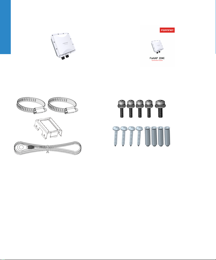
Box Includes
FortiAP device QuickStart Guide
Pole Mount Straps (X2),
Wall Mount Bracket, and
Grounding Cable 6M
4
Pole and Wall Mounting Kits:
Machine Pan M4x10L screws (X4), Machine pan
M5x10L screw, Self-Tapping Steel Pan P3x20L(X4),
and PlasticConicalwall anchors (X4)
Page 5
Before YouBegin
Write down details typically provided by your network administrator or ISP.
Static IPaddress
IPaddress ___________________
Subnet Mask ___________________
Default Gateway ___________________
Primary/Secondary DNS ___________________
DHCP
It is normal to not require a hostname, but your ISP might require it.
Hostname ___________________
QuickStart Guide Video
https://video.fortinet.com/video/177/
fortigate-and-fortiap
5
Page 6
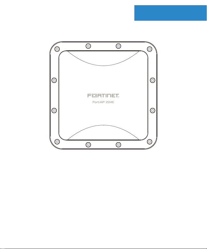
FortiAP 224E - Device Front
Device Guide
6
Page 7
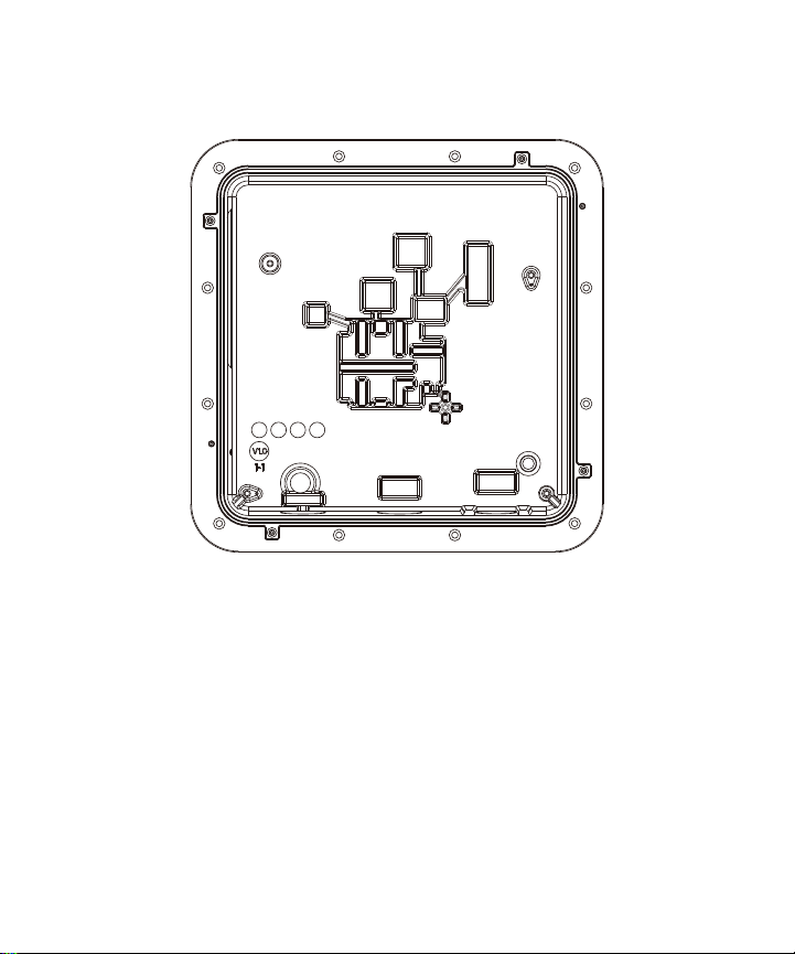
FortiAP 224E - Device Rear
7
Page 8
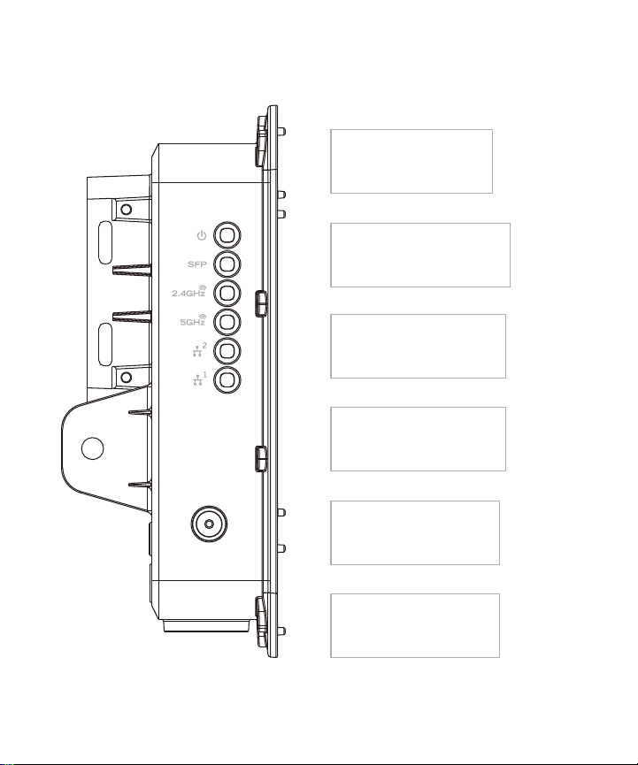
FortiAP 224E - Device Side (LEDs)
1
4
3
2
5
6
Green: System is ready
O: Power o
Amber: System is booting up
O: System booted
1: Power
2: Small form-factor pluggable (SFP)
3: 2.4GHz WLAN
4: 5GHz WLAN
5: LAN2
6: LAN1 (PoE)
Green: Connect to optical port
Blinking: Optical activity present
O: No activity or power o
Amber: Reserved
Green: Connect to WLAN port
Blinking: WLAN activity present
O: No activity or power o
Amber: Reserved
Amber: Device connected to
LAN port at 10/100/1000Mbps
Blinking: LAN activity present
O: Not connected
Green: Connect to WLAN port
Blinking: WLAN activity present
O: No activity or power o
Amber: Reserved
Amber: Device connected to
LAN port at 10/100/1000Mbps
Blinking: LAN activity present
O: Not connected
8
Page 9
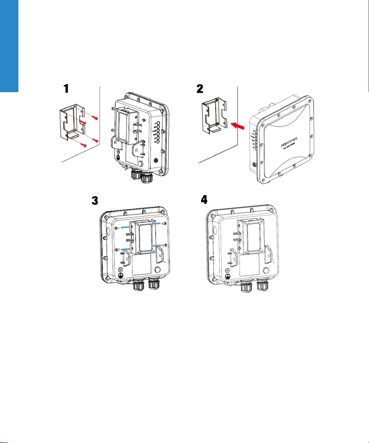
Installation
Mount on Wall
9
Page 10
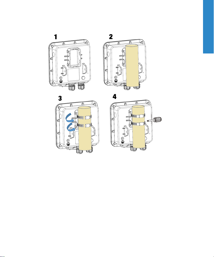
Mount on Pole
10
Page 11

Rotating Mount
Fasten the Hold Bracket (1) and the Bracket Sheets (2) to the base using the
M8x32L Hexagon screw bolts and washers:
Fasten the Pole Bracket & Wall Bracket to the pole using supplied M8x160L
Hexagon screw bolts (5 and 6):
11
Page 12

Fasten the Pole Bracket to the Wall Bracket by securing the supplied M8x32L
Hexagon screw bolts (7, 8, and 9):
12
Page 13

To adjust the unit to tilt up and down:
13
Page 14

To adjust the unit to tilt left and right:
14
Page 15

A
Cabling
The unit requires 48VDC power, which is delivered by the PoE injector over a
straight-through Ethernet cable.
To install the weatherproof connector
1.
Unscrew the coupling ring from the waterproof connector, remove the
sealing gland, and thread the RJ-45 plug through the connector
components.
2.
Insert the RJ-45 plug into the PoE port on the unit and install the
weatherproof panel connector onto the threaded coupling at the port.
3.
Slide the sealing gland along the cable into the panel connector.
4.
Thread the coupling ring into the panel connector and tighten it until the
sealing gland is compressed, making a watertight seal on the cable.
15
Page 16

Basic Connection
WAN/POE
Network Core/FortiGate
Connect the FortiAP device to a FortiGate controller or an Internet connection.
Ensure that the Power over Ethernet (PoE) cable is connected to an applicable
port on your FortiGate device or PoE injector.
Caution: Adequate grounding must be provided to the FortiAP unit and
the PoE injector, in compliance with your local electrical code or
regulations.
Warning: This device complies with IEEE 802.3af PoE specification. Do
not use any PoE injectors that are not IEEE 802.3af compliant as they
may damage your device.
16
Page 17

FortiAPSetup
Deployment through a FortiGate
Ensure that you are running the Fortinet recommended version of
software. Please check support.fortinet.com for more information.
If FortiGate is on the same network as the FortiAP:
1.
Use FortiGate to preauthorize the FortiAP device.
2.
Refer to the “Access Point Deployment” section of the FortiWiFiand
FortiAP Configuration Guide found at http://forti.net/ap-docs.
3.
Plug the FortiAP into your local Ethernet connection. The FortiAP will selfconfigure.
Or
1.
Instead of preauthorizing, you can use the FortiGate to authorize the
FortiAP device after you have connected the FortiAP to the network.
2.
Within two minutes of connecting the FortiAP to the FortiGate, the device
appears on the Managed FortiAP page in the Web-based Manager:
authorize and assign a profile to the device.
17
Page 18

If FortiGate is not on the same network as the FortiAP:
1.
Log into FortiAP directly (IP address: 192.168.1.2) with username admin
and no password, and specify the IP address of the controlling FortiGate.
2.
Connect to FortiAP via the CLI using the instructions in the “Connecting
to FortiAP CLI” section of the FortiWiFi and FortiAPConfiguration guide.
3.
Specify the IP address of the controlling FortiGate:
config capwap wtp acIpAddr 0.0.0.0
where 0.0.0.0 is the address of the FortiGate.
4.
The FortiAP device connects to FortiGate, and then you can authorize the
FortiAP.
18
Page 19

Cautions and Warnings
Environmental specifications
Ambient operating temperature: -30C to 60C
Refer to specific Product Model Data Sheet for Environmental Specifications(Operating Temperature,
Storage Temperature, Humidity, and Altitude)
Référez à la Fiche Technique de ce p roduit pour les caractéristiques environnementales (Température
de fonctionnement, temp érature de stockage, humidité et l'altitude).
Safety
Warning: Equipment intended for installation in Restricted Access Location.
Avertissement: Le matériel est conçu p our être installé dans un endroit où l’accès est restreint.
Caution: This equipment is to be used in a Network Environment 0 per IECTR62101. This product is
connected only to PoE networks without routingto the outside plant.
Attention: Ce matériel doit être utilisé dans un Environnement Réseau 0 par IECTR 62101. Ce produit
est uniquement connecté aux réseaux PoE sans installation externe de routage.
This product is intended to be supplied 48-57 Vd c from PoE source.
Le produit doit être alimenté par à de 48-57 Vdc (PoE).
Grounding — To prevent damage to your equipment, connections that enter from outside the building
should pass through a lightning/ surge protector, and be properly grounded. Use an electrostatic
discharge workstation (ESD) and/or wear an anti-static wrist strap while you work. In addition to the
grounding terminal of the plug, on the back panel, there is another, separate terminal for earthing.
Miseà la terre — Pouréviter d’endommager votre matériel, assurez-vous que les branchements qui
entrent à partir de l’extérieur du bâtiment passent par un parafoudre / parasurtenseur et sont
correctement mis à la terre. Utilisez un poste de travail de déchargeélectrostatique (ESD) et / ou portez
19
Page 20

un bracelet anti-statique lorsque vous travaillez. Ce produit possède une borne de mise à la terre qui
est prévu à l’arrière du produit, à ceci s’ajoute la mise à la terre de la prise.
This product has a separate protective earthingterminal provided on the back of the product in
additionto the grounding terminal of the attachment plug. This separate protective earthing terminal
must be permanently connected to earth with a green with yellow stripe conductorminimum size # 14
AWG and the connectionis to be installed by a qualified service personnel.
Ce produit a une borne de mise à la terre séparé sur le dos de l'appareil, en plus de la borne de mise à
la terre de la fiche d e raccordement. Cette borne de mise à la terre séparée doit être connecté en
permanence à la terre avec un conducteur vert avec la taille bande jaune de minimum # 14 AWG et la
connexion doit être installé par un personnel qualifié.
The connectingcable between the outdoor equipment and the indoor ITE devices should comply with
Class 3 wiring methods as listed in NEC, Table 725.154(G)for Class 3 Cable Substitutions.
Le câble connectantl’équipement extérieur et ceux d’intérieur de type ITE doit être conforme avec les
méthodes de câblage de classe 3 tel que listé dans le standard NEC, Table 725.154(G)pour les câbles
de substitutions de classe 3.
PoE input cab le type should be CL3, CL3P, CL3R, CL3X, marked "SUNLIGHT RESISTANT", "SUN.
RES.", or "SR." and "water resistant" or "W".
Le type de câble PoE d'entrée doit être CL3, CL3P, CL3R, CL3X marqué "SUNLIGHT RESISTANT".
"SUN RES.» Ou «SR». et "waterproof" ou "W".
If further assistance is needed with purchasinga power source and POE input cable, please contact
Fortinet, Inc.
Si vous avez besoin de plus d'aide à l'achat de l'alimentation et le fil d'entrée PoE, s'il vous plaît
communiquer avec Fortinet, Inc.
The Console port is not intended to be connected to the computer after the outdoor installation is
completed.
20
Page 21

La porte Console n’est pas destinée à être raccordée à l’ordinateur après l’installation extérieure faite.
This equipment is to be connected only to PoE networks (LPS)and maybe installed outdoors except
the Surge Protector, the PoE Injectorand its external LPS Power Supply which are intended for indoor
installation only.
Ce produit doit être connecté uniquement aux réseaux POE et peut être installé à l'extérieur sauf le
protecteur de surtension, l'injecteur PoE et son alimentation LPS externe qui sont destinés à une
installation intérieure seulement
Regulatory Notices
Federal Communication Commission (FCC) – USA
This device complies with Part 15 of FCC Rules. Operation is subject to the following two conditions:
(1)this device may not cause harmful interference, and
(2)this device must accept any interference received; includinginterference that may cause undesired
operation.
This equipment has been tested and found to comply with the limits for a Class B digital device,
pursuant to Part 15 of the FCC Rules. These limits are designed to provide reasonable protection
against harmful interference in residential installation. This equipment generates, uses, and can radiate
radio frequency energy, and if it is not installed and used in accordance with the instruction manual, it
may cause harmful interference to radio communications. However, there is no guarantee that
interference will not occur in a particular installation.
If this equipment does cause harmful interference to radio or television reception, which can be
determined by turning the equipment off and on, the user is encouraged to try to correct the
interference by one or more of the followingmeasures:
21
Reorient or relocate the receivingantenna.
Increase the separation between the equipment and receiver.
Connect the equipment into an outlet on a circuit different from that to which the receiver is
connected.
Consult the dealer or an experienced radio/TV technician for help.
Page 22

WARNING: Any changes or modifications to this unit not expressly approved by the party responsible
for compliance could void the user’s authority to operate the equipment
This equipment complies with FCC radiation exposure limits set forth for an uncontrolled environment.
This equipment should be installed and operated with minimum distance 32 cm between the radiator
and your body. This transmitter must not be co-located or operating in conjunction with any other
antenna or transmitter.
This device meets all the other requirements specified in Part 15E, Section15.407 of the FCC Rules.
Industry Canada Equipment Standard for Digital Equipment (ICES) –
Canada
This Class B digital apparatus complies with Canadian ICES-003.
Cet appareil numérique de la classe B est conforme à la norme NMB-003du Canada.
Innovation, Science and Economic Development (ISED) – Canada
This device complies with Industry Canada’s licence-exempt RSSs. Operation is subject to the
following two conditions:
(1)This device may not cause interference; and
(2)This device must accept any interference, including interference that may cause undesired
operation of the device.
Le présent appareil est conforme aux CNR d'Industrie Canada applicables aux appareils radio
exempts de licence. L'exploitationest autorisée aux deux conditions suivantes:
(1)l'appareil ne doit pas produire de b rouillage, et
(2)l'utilisateur de l'appareil doit accepter tout brouillage radioélectrique subi, même si le brouillage est
susceptible d'en compromettre le fonctionnement.
Forproduct available in the USA/Canada market, only channel 1~11 can be operated. Selection of
other channels is not possible.
22
Page 23

Pourles produits disponibles aux États-Unis / Canada du marché, seul le canal 1 à 11 peuvent être
exploités. Sélectiond'autres canaux n'est pas possible.
This equipment complies with ISED radiation exposure limits set forth for an uncontrolled environment.
This equipment should be installed and operated with minimum distance 32 cm between the radiator &
your body.
Cet équipement est conforme aux limites d'expositionaux rayonnements ISED établies pour un
environnement non contrôlé. Cet équipement doit être installé et utilisé avec un minimum de 32 cm de
distance entre la source de rayonnement et votre corps.
Caution: The device for the band 5150-5250 MHz is only for indoor usage to reduce potential for
harmful interference to co-channelmobile satellite systems. High-power radars are allocated as
primary users (i.e. priority users) of the bands 5250-5350 MHz and 5650-5850MHz and that these
radars could cause interference and/or damage to LE-LAN d evices.
Attention: Le dispositif de la bande 5150-5250 MHz est réservé à un usage intérieur afin de réduire
l'interférence nuisible potentielle aux systèmes mobiles par satellite co-canal. Les radars à haute
puissance sont désignés comme utilisateurs principaux (à savoir les utilisateurs p rioritaires) des
bandes 5250-5350 MHz et 5650-5850 MHz et que ces radars pourraient causer des interférences et /
ou endommager les périphériques LE-LAN
This device has been designed to operate with an antenna havinga maximum gain of 5.9 dBi for
2.4GHz and 6.5 dBi for 5GHz. Antenna having a highergain is strictly prohibited per regulations of
ISED. The required antenna impedance is 50 ohms.
Under ISED regulations, this radio transmitter may only operate using an antenna of a type and
maximum (orlesser) gain approved for the transmitter by ISED. To reduce p otential radio interference
to other users, the antenna type and its gain should be so chosen that the equivalent isotopically
radiated power (e.i.r.p.) is not more than that necessary for successful communication.
Ce dispositif a été conçu pour fonctionneravec une antenne ayant un gain maximal de 5.9 dBi pour 2,4
GHz et 6.5 dBi pour 5GHz. Une antenne ayant un gain supérieur sont strictement interdites par la
réglementation d'ISED. L'impédance d'antenne requise est de 50 ohms.
23
Page 24

Conformément à la réglementationd'ISED, cet émetteur radio peut fonctionner seulement avec une
antenne d’un type et d'un gain maximal (ou inférieur) approuvé pour l'émetteur par ISED. Dans le but
de réduire les risques de brouillage radioélectrique aux autres utilisateurs, il faut choisir le type
d'antenne et son gain de sorte que la puissance isotrope rayonnée équivalente (p.i.r.e.) ne dépasse
pas l'intensité nécessaire à l'établissement d'une communication réussie.
This radio transmitter (IC: 7280B-2517Q021)has been approved by ISED to operate with the antenna
types listed below with the maximum permissible gain and required antenna impedance for each
antenna type indicated. Antenna typ es not included in this list, havinga gain greater than the maximum
gain indicated for that type, are strictly prohibited for use with this device.
Le présent émetteur radio (IC: 7280B-2517Q021)a été approuvé par ISED pour fonctionner avec les
types d'antenne énumérés ci-dessous et ayant un gain admissible maximal et l'impédance requise
pour chaque type d'antenne. Les types d'antenne non inclus dans cette liste, oudont le gain est
supérieur au gain maximal indiqué, sont strictement interdits pour l'exploitationde l'émetteur.
This device and it's antennas(s) must not be co-located or operating in conjunction with any other
antenna or transmitter except in accordance with IC multi-transmitter product procedures.
Cet appareil et son antenne (s) ne doit pas être co-localisés ou fonctionnement en association avec une
autre antenne ou transmetteur.
24
Page 25

Gain (dBi)
Qty MPN
RFMTA400809MMLB901
1
RFMTA400811MMLB901
1
RFMTA400814MM5B901
1
RFMTA400816MM5B901
1
RFPCA381017MMAB702
1
Antenna
Type
Metal
Antenna
Metal
Antenna
Metal
Antenna
Metal
Antenna
PCB
Antenna
Antenna
Connector
2.4GHz
Band1Band2Band3Band
5GHz
MMCX 5.9 - - - -
MMCX 5.9 - - - -
MMCX - 6.2 6.5 6.5 6.4
MMCX - 6.2 6.5 6.5 6.4
MMCX 8.6 - - - -
4
Professional Installation Instruction
1. Installationpersonnel
This product is designed for specific application and needs to b e installed by qualified personnel who
has RF and related rule knowledge. The general user shall not attempt to install or change the settings.
2. Installationlocation
The product shall be installed at a location where the radiating antenna can be kept 32 cm from nearby
person in normal operation condition to meet Regulatory RF exposure requirement. The installation
applies to both indoor and outdoor location.
25
Page 26

3. Antenna(s)
Use only the antenna(s)that have been approved by the manufacturer. The non-approved antenna(s)
may produce unwanted spurious or excessive RF transmitting power that may lead to the violation of
FCC/ISED limit and is prohibited.
4. Warning
Please carefully select the installation position and ensure that the final output power d oes not exceed
the limit set forth in relevant rules. The violation of the rule could lead to serious federal penalty.
Instructions d'installation professionnelle
1. Installation
Ce produit est conçu pour un usage spécifique et doit être installé par un personnel qualifié maîtrisant
les radiofréquences et règle similaires. L'utilisateur ne doit pas tenter d'installer ou de modifier les
paramètres.
2. Emplacement d'installation
En usage normal, afin de respecter les exigences réglementaires concernant l'expositionaux
radiofréquences, ce produit doit être installe de façon à respecter une distance de 32 cm entre
l'antenne émettrice et. L'installation s'applique aux emplacements intérieur et extérieur.
3. Antenne(s)
Utiliser uniquement l'antenne (s) approuvées par le fabricant. L'utilisation d'autres antennes peut
conduire à un niveau de rayonnement essentiel ou non essentiel dépassant les niveaux limites définis
par FCC/ISED, ce qui est interdit.
4. Avertissement
Choisir avec soin la position d'installation et s'assurer que la puissance de sortie ne dépasse pas les
limites en vigueur. La violation de cette règle peut conduire à de sérieuses pénalités fédérales.
26
Page 27

European Conformity (CE) - EU
This is a Class B product. In a domestic environment, this product may cause radio interference, in
which case the user may be required to take adeq uate measures.
The product transmits within the frequency ranges and less than or equal to the power listed below:
2412-2472MHz less than 20dBm
5180-5240MHz less than 23dBm
5260-5320MHz less than 23dBm *
5500-5700MHz less than 30dBm *
Note: * Only with DFS bands certification.
This equipment should be installed and operated with minimum distance 32cm between the radiator &
your body.
Simplified EU Declaration of Conformity
This declaration is only valid for Fortinet products (including, combinations of software, firmware and
hardware) provided by Fortinet or Fortinet’s authorized p artners to the end customer directly for use
within the EU or countries that have implemented the EU Directives and/or spectrum regulation. Any
Fortinet products not obtained directly from Fortinet or Fortinet’s authorized partners may not comply
with EU Directives and Fortinet makes no assurances for such products.
Бъл гарски
Този проду кт е в съ о тве тствие с Дире ктив а 2014/53/ЕС.
Česky
Tentoprodukt je v souladu se směrnicí 2014/53/EU.
Dansk
Dette produkt er i overensstemmelse med direktiv 2014/53/EU.
27
Page 28

Deutsch
Dieses Produkt entspricht der Richtlinie 2014/53/EU.
Eesti
See toode vastab direktiivile 2014/53/EL.
English
This product is in compliance with Directive 2014/53/EU.
Español
Este producto cumple con la Directiva 2014/53/UE.
Ελλη ν ική
Το προϊόν α υτ ό συμμορ φ ώ ν ετ α ι με τ ην Οδηγία 2014/53/ΕΕ.
Français
Ce produit est conforme à la Directive 2014/53/UE.
Hrvatski
Ovaj proizvod je u skladu s Direktivom 2014/53/EU.
Italiano
Questo prodotto è conforme alla Direttiva 2014/53/EU.
Latviski
Questo prodotto è conforme alla Direttiva 2014/53/EU.
Lietuvių
Šis gaminys atitinka direktyvą 2014/53/ES.
Malti
Dan il-prodott huwa konformi mad-Direttiva 2014/53/UE.
Magyar
Ez a termék megfelel a 2014/53/EU irányelvnek.
28
Page 29

Nederlands
Dit product is in overeenstemming met Richtlijn2014/53/EU.
Norsk
Dette produktet er i samsvar med direktiv 2014/53/EU.
Polski
Ten produkt jest zgodny z dyrektywą 2014/53/UE.
Português
Este produto está em conformidade com a Diretiva 2014/53/UE.
Rumunski
Acest produs este în conformitate cu Directiva 2014/53/UE.
Slovensky
Tentoprodukt je v súlade so smernicou 2014/53/EÚ.
Slovensko
Ta izdelek je v skladu z Direktivo 2014/53/EU.
Suomi
Tämä tuote on direktiivin 2014/53/EU mukainen.
Svenska
Denna produkt överensstämmer med direktiv 2014/53/EU.
Note: The full declarationof conformity for this product is available at the link below:
https://site.fortinet.com/ProductRegulatory/EU
The device is restricted to indoor use only when operating in the 5150 to 5350MHz frequency range in
the following countries:
29
Page 30

AT BE BG HR CY CZ DK
EE FI FR DE EL HU IE
IT LV LT LU MT NL PL
PT RO SK SI ES SE UK
30
Page 31

Fortinet Customer Service & Support
Create a support account, register and manage your products,
download updates, firmware images and release notes, and create
technical support tickets.
https://support.fortinet.com
Fortinet Document Library
Up-to-date versions of Fortinet publications for the entire family of
Fortinet products.
http://docs.fortinet.com
Training Services
Course descriptions, availability, schedules, and location of training
programs in your area.
http://www.fortinet.com/training
Technical Discussion Forums
Communicate with other customers and Fortinet partners about
Fortinet products, services, and configuration issues.
https://support.fortinet.com/forum
FortiGuard Threat Research and Response
Up-to-date information on vulnerabilities and threats, includes a
virus scanner, IP signature look-up, and web filtering tools.
http://www.fortiguard.com
Fortinet.com
 Loading...