

Page 1

FD 280
Double-Head Edge Tabbing System
Operator Manual
10/2011 First Edition
Page 2

Page 3

TABLE OF CONTENTS
1. INTRODUCTION .............................................................................................. 1
1.1 Organization of this Operating Manual ........................................................... 1
1.2 FD 280 Description ......................................................................................... 1
1.3 Items Included ................................................................................................ 3
1.4 Operating Manual Safety Terms ..................................................................... 4
1.5 Safety Precautions .......................................................................................... 5
1.6 Operating Manual Terms ................................................................................ 5
1.7 Warranty ......................................................................................................... 6
2. SPECIFICATIONS & REQUIREMENTS .......................................................... 8
2.1 Specifications .................................................................................................. 8
2.2 Operating Requirements ................................................................................. 8
3. POWER CONNECTION ................................................................................... 9
3.1 Safety .............................................................................................................. 9
3.2 Line Voltage .................................................................................................... 9
3.3 Line Fuses .................................................................................................... 11
3.4 Accessory Fuses........................................................................................... 12
3.5 Accessory Power Outlet ................................................................................ 13
3.6 Power Cord ................................................................................................... 13
4. CONTROLS .................................................................................................... 14
4.1 Power Switch ................................................................................................ 14
4.2 LCD Counter ................................................................................................. 14
4.3 Control Panel
4.3.1 Power Indicator .............................................................................................. 15
4.3.2 Stop ................................................................................................................ 15
4.3.3 Start .............................................................................................................. 15
4.3.4 Tab Ready……………… ……………………………………………………… 15
4.4 Head Position Knob ...................................................................................... 16
4.5 Tab Mode Switch .......................................................................................... 16
5. FEEDING DEVICES ....................................................................................... 17
5.1 Placing the FD 280 In-Line ........................................................................... 17
5.2 ACCESSORY ITEMS ................................................................................... 18
5.2.1 Fan Fold Tab Stand………………………………………………………………...18
5.2.2 FD 280 Short Cart .......................................................................................... 19
5.2.3 FD 280 Long Cart………………………………………………………….………..19
5.2.4 FD 280-20 Label Delivery Module ………….…………………………………….19
Page 4

6. OPERATION ................................................................................................... 20
6.1 Splicing Tabs ................................................................................................ 20
6.2 Threading Tabs……………………………………………………………………21
6.3 Feeding Portrait Mail Pieces ......................................................................... 22
6.4 Feeding Landscape Pieces .......................................................................... 24
6.5 Tabbing Mail Pieces ..................................................................................... 25
6.6 Adjusting Tab Position …………………………………………………………..26
6.7 Remove Waste Backing Paper…………………………………………………27
6.8 Restore Default Tab Settings……………………………………………………27
6.9 Change Piece Size………………………………………………………………27
7. MAINTENANCE .............................................................................................. 28
7.1 General Cleaning & Clearing ........................................................................ 28
7.2 Replacing a Fuse .......................................................................................... 29
7.2.1 Line Fuse........................................................................................................ 30
7.2.2 Accessory Fuse .............................................................................................. 31
8. TROUBLESHOOTING ................................................................................... 32
8.1 Troubleshooting Chart .................................................................................. 32
9. CORRECTING TABBING PROBLEMS ......................................................... 35
9.1 No Tabs Applied To Mail Pieces
9.1.1 Tab Ready Light Off ........................................................................................ 35
9.1.2 Mail Piece Jam ........................................................................................ 35
9.1.3 Torn Backing Paper ........................................................................................ 36
9.2 Incorrect Threading ..................................................................................... 37
9.3 Poor Tab Placement or Appearance…………………………………………...38
9.3.1 Tab Placement Is Inconsistent .................................................................. 38
9.4 Uneven tab Folds……………………………………………………..…………..38
9.5 Restoring factory settings ………………………………………………………..39
10. SERVICE ...................................................................................................... 40
10.1 Service ........................................................................................................ 40
10.2 Repacking Instructions................................................................................ 40
Page 5

1
1. INTRODUCTION
1.1 Organization Of
This Operating
Manual
1.2 ET Description
This manual starts with a description of your FD 280,
then describes its set up, operation and maintenance.
Finally, information is offered to help you determine
what can go wrong and what to do about it. There
are many helpful tips along the way, and it is strongly
suggested that you become familiar with this entire
manual prior to operating the FD 280.
The FD 280 is an automatic tabbing machine used to
seal open mail pieces. Tabs are peeled from rolls or
fan folds of backing paper and applied to mail pieces
such as self-mailers, booklets, brochures, newsletters
and double postcards.
Mail pieces are fed into the FD 280 using a feeding
device such as the Formax FD 260-10 Feeder, a
feeder or labeler from another manufacturer. If the
FD 280 is to work correctly, mail pieces must be fed
into it correctly -- with a gap of about one inch
between mail pieces. This manual does not cover the
operation of the various feeding devices that may be
used to supply the FD 280 with mail pieces. Please
read your feeding device operating manual before
using it in-line with the FD 280.
NOTE
Some feeding devices require a stand
in order to operate in-line with the FD 280.
Check with your Formax dealer.
The FD 280 uses two tabbing heads to advance
pressure-sensitive tabs past a peel bar. Partially
peeled tabs hang from the backing paper, ready to be
peeled at the peel bar before they contact the mail
piece. Tabs are pressed and folded onto mail pieces
between a set of belts and rollers. The tabbed mail
pieces exit the FD 280 and can be collected in an
optional Catch Tray or stacked by a Formax
FD 260-20 Conveyor.
Page 6

2
Tab quality is as important as mail piece quality. Poor
quality tabs and mail pieces take longer to run, jam
often and produce poor results. Only genuine
Formax brand tabs are 100% guaranteed to run on
Formax Tabbers. Imitation tabs can be run on Formax
Tabbers, but are not guaranteed to run problem-free.
The FD 280 depends on a smooth flow of both tabs
and mail pieces. This flow is monitored by a set of
sensors and a microprocessor. As with most
microprocessor-controlled machines, the FD 280
needs a few seconds to get itself ready to run. When
you turn the power on, the FD 280 takes 5 seconds to
boot up. During this time the tab ready light flashes
and the control panel is inoperative.
Signals from sensors and the encoder are fed to the
microprocessor which monitors the length of pieces
fed and calculates the average length of the piece.
Without correct measuring, the FD 280 will not tab.
The FD 280’s sensors work like all other electric eyes.
When an object breaks the beam of light (the
SENSOR BEAM) between them, an electrical signal
is generated. It is imperative that this SENSOR
BEAM PATH be maintained in its proper condition
and alignment at all times.
Debris and stray tabs can become caught in the
paper path and sensor beam. Rough, careless
handling of the FD 280 can cause the sensors to
become mis-aligned. Both of these conditions must
be prevented. The FD 280 requires periodic cleaning
and reasonable handling. Paper dust build-up or
abuse will bring the successful operation of the FD
280 to an end. Take care of your FD 280 by following
the set up, operation and maintenance instructions in
this manual.
Page 7
3
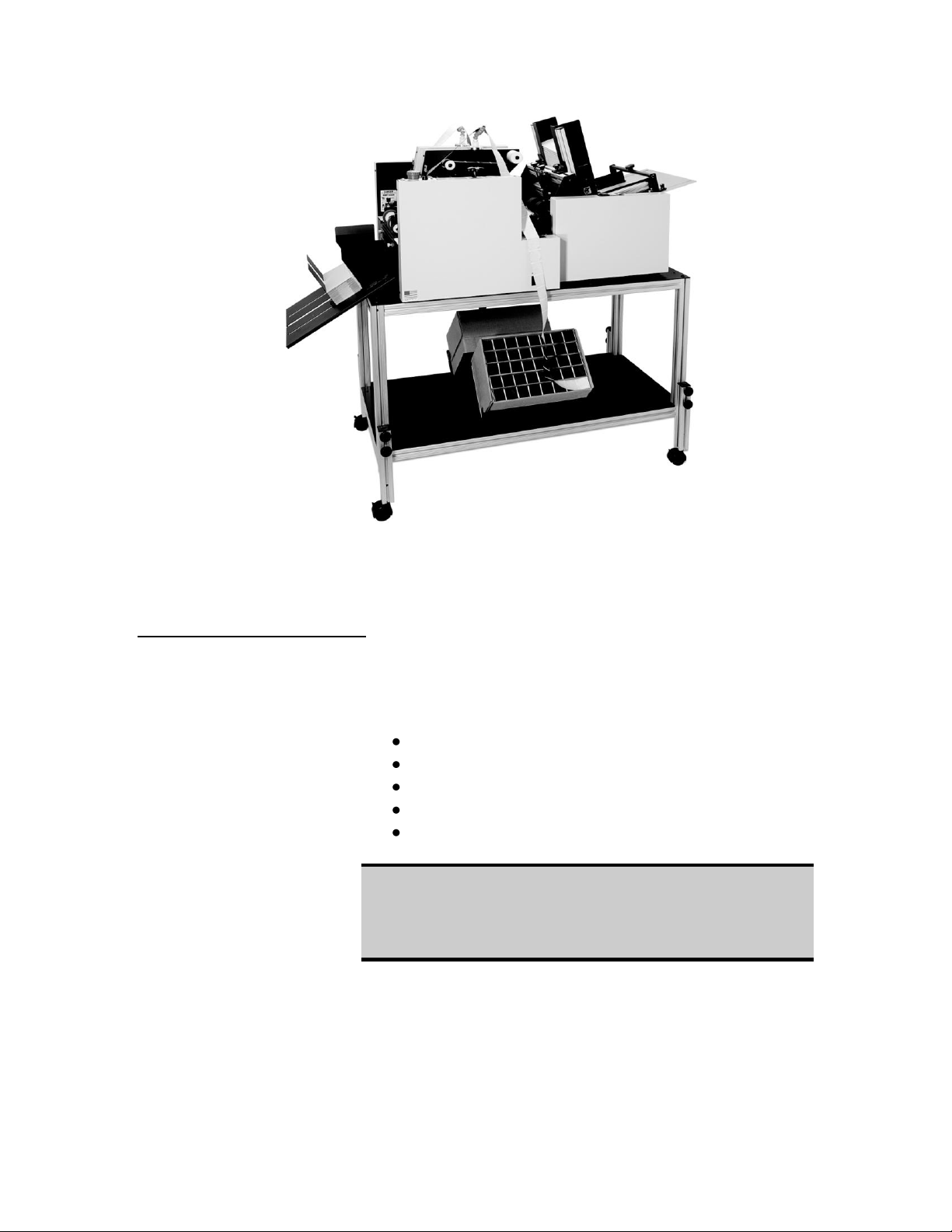
Figure 1.1 – Formax FD 280 with FD 280-10 High Volume Feeder and stand.
1.3 Items Included
The following items are shipped together in one box.
Take note of each as you unpack the box.
FD 280 Tabber with input shafts
Power cord
Catch Tray
2 Magnetic Tab Guides
Operating Manual
WARNING
THE FD 280 IS A HEAVY MACHINE.
USE PROPER LIFTING TECHNIQUES
TO SET IT ON A WORK SURFACE.
Page 8

4
1.4 Operating
Manual Safety
Terms
The following highlighted blocks are used throughout
this manual to emphasize important information.
Pay careful attention to this information.
WARNING
ALERTS YOU TO ACTIONS OR CONDITIONS
THAT MAY PRESENT HAZARDS OR CAUSE
INJURY TO PERSONNEL.
CAUTION
ALERTS YOU TO ACTIONS THAT MAY CAUSE
LOSS OF MATERIALS (MAIL PIECES AND TABS)
OR DAMAGE TO EQUIPMENT.
NOTE
Draws your attention to an important
statement or action.
TIP
A suggestion to enhance the
FD 280’s productivity.
Page 9

5
1.5 Safety
Precautions
Observe the following safety precautions and
warnings when operating, cleaning or repairing the
FD 280. Failure to do so may result in physical injury
or damage to the FD 280. The manufacturer
assumes no liability for your failure to comply with
these requirements.
WARNING
NEVER CLEAN, CLEAR OR DISASSEMBLE THE
FD 280 WITHOUT FIRST UNPLUGGING THE
POWER CORD.
WARNING
KEEP LOOSE CLOTHING, TIES, SCARVES AND
HAIR AWAY FROM ALL MOVING PARTS.
1.6 Operating
Manual Terms
WARNING
DO NOT PLACE FINGERS OR TOOLS BETWEEN
OR NEAR MOVING PARTS.
OBSERVE ALL POSTED WARNING DECALS
The following terms are used throughout this manual:
input end where mail pieces enter
output end where mail pieces exit
operator side side where the controls are
located
non-operator side opposite the operator side
Page 10

6
1.7 Warranty
NOTE
Your FORMAX FD 280 is covered under warranty
by the dealership from which you purchased it.
Formax warrants your FD 280 against defects in
materials and workmanship for a period of six months
from the original ship date when used in accordance
with the operating instructions in this manual. This
warranty covers the cost of parts when the machine is
presented by its original purchaser to an authorized
FORMAX Service Center. Should warranty repairs
become necessary, the service provider, at his/her
option, will repair or replace such parts required to
restore the FD 280 to serviceable condition.
This warranty does not cover consumable parts such
as belts, rollers and sweeps used to contact and
transport mail pieces and tabs. This warranty does
not extend to incidental or consequential damages
arising out of a warranty claim, or to costs associated
with maintenance of the equipment. This warranty
does not cover damages resulting from shipping,
accident, misuse, abuse, neglect, mishandling,
alteration or modification. Your rights under this
warranty may vary from state to state.
Page 11

7
2. SPECIFICATIONS & OPERATING REQUIREMENTS
2.0 Specifications
Size & Weight
20" L x 18" H x 24" W
67 lb. assembled
Power
Possible line voltages are 240V, 230V, 220V,
120V, and 100V at 50-60 Hz
2.1 Operating
Requirements
Mail Piece Size
Height: 31/2" minimum, 9" maximum
Width: 5.5" minimum, 12" maximum
Mail Piece Thickness
Minimum: single sheet of 20 lb. bond paper
tri-folded – 2 tabs.
Maximum: .200”
Tab Specs
Tab width: 1" and 1.5" fan fold or roll
Tab length: 1", 1.5”
Backing paper width: between 1.125" (1" tab) and
1.625 " (1.5" Tabs)
Maximum roll diameter: 10.00" Core Diameter: 3"
Fan Fold: Case Based
Clear or translucent tabs require blacked out tab
areas.
Tab Position Accuracy
1
±
/8" guaranteed when using Formax
their specified shelf life
Mail Piece Fold Quality
Folds in mail pieces should result in flush panels.
Mail piece squareness is important when meeting
USPS tab tenting specifications.
Production
Over 15,000 mail pieces (8.4" long) per hour
®
Tabs within
Page 12

8
3. POWER CONNECTION
BEFORE PLUGGING THE FD 280 INTO AN
OUTLET, CAREFULLY READ THE FOLLOWING
INFORMATION ABOUT VOLTAGES, FUSES AND
3.1 Safety
The FD 280 can connect to any power distribution
system, including the European IT Power System.
Because the European IT Power System does not
have a grounded neutral leg, the FD 280 uses
protective fusing in both the neutral and hot supply
lines of power.
WARNING
THE POWER CORD.
3.2 Line Voltage
WARNING
A BLOWN FUSE IN THE NEUTRAL LEG COULD
MEAN INTERIOR PARTS OF THE FD 280 REMAIN
AT A HAZARDOUS VOLTAGE. ALWAYS UNPLUG
THE POWER CORD BEFORE REMOVING COVERS
FROM THE FD 280.
The FD 280 is rated for continuous operation using a
variety of supply voltages. Possible line voltages are
240V, 230V, 220V, 120V and 100V at 50 or 60 Hz.
The manufacturer configures the FD 280 to operate
with the voltage requested by the customer.
CAUTION
VERIFY THE CORRECT VOLTAGE
SETTING BEFORE PLUGGING THE FD 280
INTO AN OUTLET.
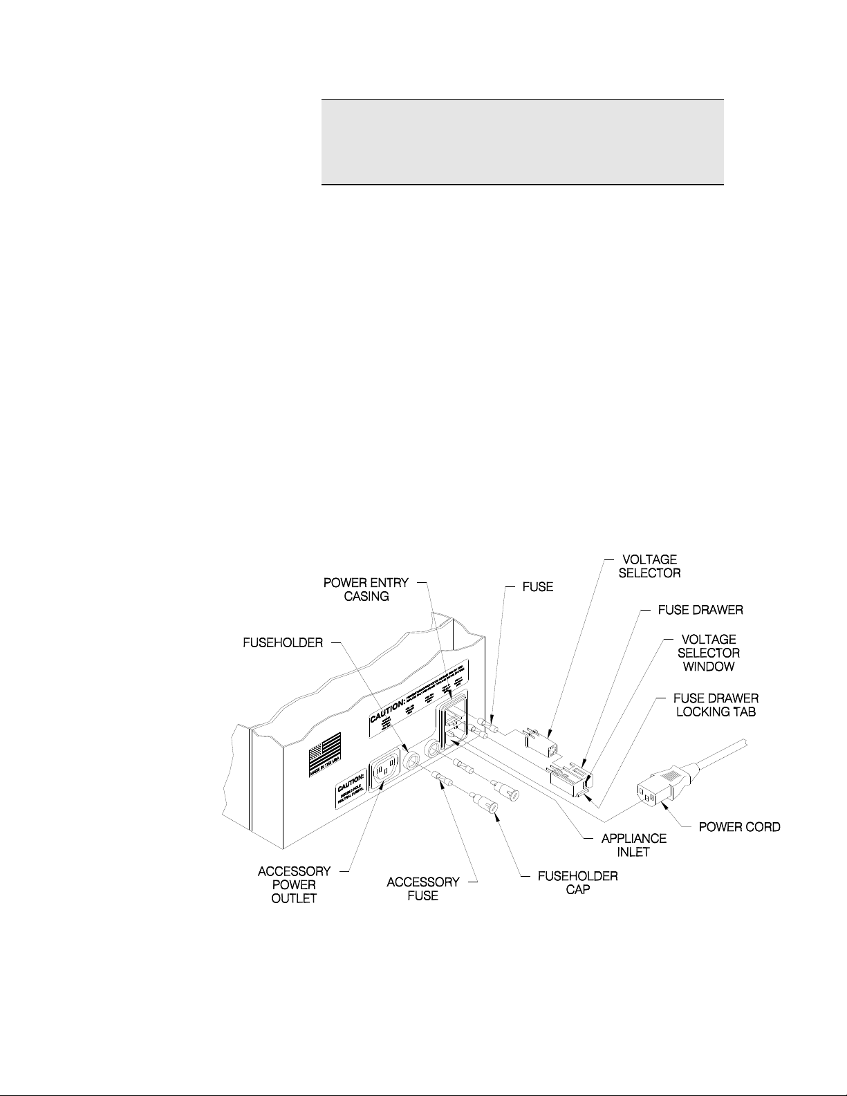
Read the current voltage setting through the
VOLTAGE SELECTOR WINDOW on the nonoperator side of the FD 280. (Refer to Figure 3.1.)
Use the following instructions to change the voltage
setting:
Page 13
9
NOTE
The detachable POWER CORD may need to be
changed to match the particular power-source
output.
1. Unplug the POWER CORD.
2. Use a small screwdriver or similar tool to push up
on and release the FUSE DRAWER LOCKING
TAB.
3. Pull the FUSE DRAWER out of the POWER
ENTRY CASING.
4. Pull the VOLTAGE SELECTOR out of the FUSE
DRAWER.
5. Rotate the VOLTAGE SELECTOR until the correct
voltage is on the same side as the VOLTAGE
SELECTOR WINDOW.
6. Place the VOLTAGE SELECTOR in the FUSE
DRAWER and verify the correct voltage selection.
7. Place the FUSE DRAWER in the POWER ENTRY
CASING.
Figure 3.1 – FD 280 Power Connection
Page 14

10
3.3 Line Fuses
The FUSE DRAWER located on the non-operator
side contains two LINE FUSES. (Refer to Figure 3.1.)
The neutral and hot lines of power are fused. Both
LINE FUSES must be intact for the FD 280 to operate
properly.
CAUTION
VERIFY THAT THE LINE FUSE VALUE IS
CORRECT FOR THE VOLTAGE SETTING.
UNPLUG THE FD 280 BEFORE STARTING THIS
PROCEDURE.
Use the following instructions to verify that the LINE
FUSES installed have the proper fuse value or to
replace a blown fuse:
1. Unplug the POWER CORD.
2. Use a small screwdriver or similar tool to push up
on and release the FUSE DRAWER LOCKING
TAB.
3. Pull the FUSE DRAWER out of the POWER
ENTRY CASING. The LINE FUSES are inside.
4. Determine the proper fuse value as well as the
condition of the LINE FUSE. The fuse value is
shown on the metal tip of the LINE FUSE. The
chart below lists the selected voltage in the left
column followed by the proper fuse value in the
right column.
Selected Voltage Line Fuse Value
100V…………………….1.0A (250V time delay)
120V………………….....1.0A (250V time delay)
220V……………………..0.5A (250V time delay)
240V (or 230V)…………0.5A (250V time delay)
5. Replace the LINE FUSE if necessary. Both LINE
FUSES must be intact for the FD 280 to operate
properly.
6. Install the FUSE DRAWER in the POWER
ENTRY CASING.
Page 15

11
3.4 Accessory
Fuses
Two FUSEHOLDERS are located on the nonoperator side between the APPLIANCE INLET and
the ACCESSORY POWER OUTLET. (Refer to
Figure 3.1.) The FUSEHOLDERS hold two
ACCESSORY FUSES which protect the
ACCESSORY POWER OUTLET. As with the LINE
FUSES mentioned previously, both the neutral and
hot lines are fused. Both ACCESSORY FUSES must
be intact for the FD 280 to properly supply power to
in-line equipment.
WARNING
UNPLUG THE POWER CORD BEFORE STARTING
THIS PROCEDURE.
Use the following instructions to verify that the
ACCESSORY FUSES installed have the proper fuse
value or to replace a blown fuse:
1. Unplug the POWER CORD.
2. Use a small screwdriver or similar tool to press in
and rotate the FUSEHOLDER CAP
counterclockwise to release this cap.
3. Pull the FUSEHOLDER CAP (with the
ACCESSORY FUSE inside) out of the
FUSEHOLDER.
4. Verify the fuse value. Inspect fuses, replace if
blown.
Selected Voltage Line Fuse Value
100V…………………… 6.3A (250V time delay)
120V…………………… 6.3A (250V time delay)
220V…………………… 3.15A (250V time delay)
240V (or 230V)……….. 3.15A (250V time delay)
5. Install the ACCESSORY FUSE and the
FUSEHOLDER CAP in the FUSEHOLDER. Both
ACCESSORY FUSES must be intact for the FD
280 to properly supply power to in-line equipment.
6. Using the screwdriver, press in and turn the
FUSEHOLDER CAP clockwise to lock it.
Page 16

12
3.5 Accessory
Power Outlet
The ACCESSORY POWER OUTLET is located next
to the FUSEHOLDER on the non-operator side.
(Refer to Figure 3.1.) This outlet supplies power to
equipment running in-line with the FD 280.
Typical in-line equipment includes feeders and
labelers. Since the ACCESSORY POWER OUTLET
gets its power from the FD 280, you can control
power to in-line equipment using the FD 280’s
POWER SWITCH. Additionally, the FD 280 features
an automatic interrupt that disables the ACCESSORY
POWER OUTLET in case of a jam. The
ACCESSORY POWER OUTLET is limited to a 6.3A
maximum for 100V and 120V, and 3.15A maximum
for 220V and 240V.
3.6 Power Cord
The FD 280 comes with a three-wire POWER CORD.
The POWER CORD grounds the FD 280 when
connected to an approved three-contact electrical
outlet.
1. Plug the POWER CORD into the APPLIANCE
INLET on the non-operator side. (Refer to Figure
3.1.)
2. Plug the POWER CORD into a grounded outlet.
WARNING
TO PREVENT ELECTRICAL SHOCK, ONLY PLUG
THE POWER CORD INTO A GROUNDED OUTLET.
Page 17

13
4. CONTROLS
4.1 Power Switch
4.2 LCD Counter
The POWER SWITCH is located on the bottom of the
operator side panel. Turn the POWER SWITCH on
to supply power to the FD 280.
The LCD COUNTER is located on the right of the
operator side panel. The LCD COUNTER displays
the current number of tabbed mail pieces fed through
the FD 280. Reset the LCD COUNTER by pressing
its reset button.
Figure 4.1 - FD 280 Operator Panel Controls
Figure 4.2 Tab Pressure Controls
Page 18

14
4.3 Control Panel
4.3.1 Power Indicator
Figure 4.3 - FD 280 Control Panel
The orange Power Indicator light illuminates when the
power switch is turned on.
4.3.2 Stop
4.3.3 Start
4.3.4 Tab Ready
The STOP (red pushbutton mushroom) Switch
interrupts the movement of all moving parts and
resets the microprocessor. Once the STOP button
has been pressed, it must be lifted up into the run
position. Lifting the button will not start the machine.
Press the STOP switch to change tab mode settings.
The Start button is a momentary switch that causes
the resumption of movement after the Stop Switch
has been pressed.
Then green Tab Ready light illuminates when enough
(usually 3-4) pieces have been fed regularly through
the machine to allow precise and regular tabbing. If
the Tab Ready light stays unlit, there is a problem
with the feed mechanism as pieces are not being
counted well.
Page 19

15
4.4 Head Position
Knob
4.5 Tab Size Switch
4.6 Tab Mode Touch
Pad
Turning the Head Position Knob moves the tabbing
heads closer together or farther apart. The decal
indicates the direction. Move heads only while
machine is running.
This three position switch indicates 1.0 inch tabs (up,
used for self mailers), 1.5 inch tabs (down used for
booklets) and Set Up (Center – no tabs).
The Tab Mode Touch Pad offers the ability to select
the number, location and type of the tabs as well as
to change location of tabs. Changing mode settings
can only be done with the STOP button pressed.
Figure 4.4 FD 280 Tab Mode Touch Pad
Once the Tab Size Switch has been moved off Set
Up to a tab size, pressing the key pad selects the
tabs to be run as well as their general location on the
piece. There are three buttons per Tab Head - one
for the lead edge, the center and the trail edge.
A typical booklet setting will call for two tabs to be
selected on one head (lead and trail) and one on the
opposite (trail). To do a Booklet, use 1.5 inch tabs.
Page 20

16
To adjust the position of the tabs, press the Stop
Button and hold down the key pad for the tab to be
moved. After a second or two, the tab select light on
that pad will begin to flash. Use the Lead /Trail
arrows on the right of the touch pad to move the tab
toward the lead edge or trail edge. Ten touches of a
position arrow will result in about half an inch in
movement in the direction selected. If corresponding
tabs on the opposite head are selected, both will
move as one. Starting the transport will save your
changes.
5. FEEDING DEVICES
5.1 Placing The
FD 280 In-Line
To operate the FD 280 in-line with your feeding
device, place the output end of the feeding device
next to the input end of the FD 280. Leave about an
1
/8" gap between the machines. Align machines to
place tabs where desired on the mail pieces.
The gap between the feeding device and the FD 280
may need adjusting if the mail pieces are curled or
rigid. If the mail pieces’ leading edge curls up, the
gap should be larger than 1/8" to allow the curled edge
to come down before entering the FD 280. If the
leading edge curls down, the gap should be as small
as possible, so the mail pieces will not fall between
the two machines. A rigid mail piece may require a
larger gap if it hits the bracket above the FD 280
PAPER PATH.
NOTE
Turn on the FD 280 before turning on any feeding
device. If the FD 280 is not turned on first, it will
not accept the fed mail pieces.
Page 21

17
5.2 Accessory
items
5.2.1 FD 280-50 Fan
Fold Tab Stand
NOTE
Some equipment, when run in-line with the
FD 280, requires a stand to raise it to the level of
the FD 280. When ordering additional equipment,
specify which machine you plan to operate in-line
with the FD 280.
The FD 280-50 Tab Stand is a simple accessory that
greatly improves the operation of the machine with
fan fold tabs.
Boxes are placed on the stand – one on each side.
The boxes are tilted at the correct angle to allow for
smooth tab removal from the box. Tab columns are
spliced lead to tail to run continuously. (See Fig. 1.1)
5.2.2 FD 280-30 Stand
The FD 280-30 Adjustable Height Stand holds the
FD 280 and a Fan Fold Tab Stand. It features
adjustable height legs to allow the FD 280 to be used
in line with a number of different machines.
Page 22

18
5.2.3 FD 280-40 Stand
5.2.4 FD 280-20 High
Volume Tab
Delivery Module
The FD 280-40 Adjustable Height Stand holds the
FD 280-20 High Volume Tab Delivery Module Stand.
The FD 280-20
automatically delivers
tabs from high
volume spools to the
FD 280. One per
head is needed.
Page 23

19
6.0 OPERATION
6.1 Splicing Tabs
WARNING
KEEP LOOSE CLOTHING, TIES, SCARVES AND
HAIR AWAY FROM ALL MOVING PARTS. DO NOT
PLACE FINGERS OR TOOLS BETWEEN OR NEAR
MOVING PARTS.
It is highly recommended that splicing one tab strip to
another be the way to add or change strips of tabs.
Splicing is much quicker than threading and the
machine is delivered threaded. Splices can be made
between tab sizes.
When changing tab sizes, make sure that the
backing paper width of the tabs being run is less
than the tab width specification.
To splice tabs:
1. Stop tabbing with at least 12 inches of tab material
between the peel bar and the end of the strip.
2. Trim the last tab so that the end of the strip is
square.
3. Trim the end of the new tab strip square and
attach a tab to the underside of the strip so that it
is half on, half off the strip.
4. Remove the first few tabs from the new strip and
the last few from the old.
5. Attach the new strip to the old strip so that the end
on the old strip is on top of the new strip and in the
place of the first tab that was peeled off the new
strip. Use the tab on the new strip to stick the two
strips together.
Page 24

20
6. When a splice is made correctly no tabs will be
missed.
When running fan
folded tabs, splice
the last tab in one
stack to the first in
the succeeding
stack for continuous
operation. The tabs
are arranged in the
box to allow splicing
at any time.
Two things to
remember with fan
fold tabs. First, run
the stacks in order
from one side of the box to the other, removing stack
separators as stacks are consumed. Second, set the
box at an angle so that the tabs will always tend to fall
away from the tabber. A Formax FD 280-50 tab
stand is a simple means of accomplishing this.
6.2 Threading Tabs
Figure 6.1 – Splicing Tabs
Threading tabs is a more involved process. The tab
peeling mechanism must be removed and replaced.
Before threading take careful note of the threaded
tabs.
1. Peel at least 1-2 feet of tabs from the lead edge of
the strip to be threaded into the machine.
Page 25

21
2. Remove the peel bar mechanism by unscrewing the
knurled stainless steel knob located on the side of the
assembly.
3. Thread the strip of backing paper down through the
assembly behind the round bar and over the edge of
the peel bar.
4. Holding the backing paper up against the back of the
mechanism, replace it on the machine using the long
Stainless Steel knob.
5. Run the backing paper up and over the black rubber
roll from behind the roller. To allow space between
the black roller and the red rollers, press the
threading release lever.
6. Bring the backing paper up over the front of the red
roller, taking the slack out of the strip and squaring it
under the various rollers in the paper path. Take care
that the edge of the strip is not caught in the peel bar.
7. Take the strip back over the top plastic guide roller
and attach it to the take up spool. Check for
squareness.
Figure 6.2 Threaded Formax FD 280
Page 26

22
6.3 Feeding Portrait
Mail Piece
1. Switch the Tab Size Switch to Set-Up
2. Turn FD 280’s POWER SWITCH on. Push Stop
3. Place a sample of the piece to be tabbed between
button.
the input guides and lock the guides tight to the
edge of the piece without binding the piece.
Figure 6.3 Setting up Input Guides on the FD 280
4. Take the same sample piece and set it between the
vertical tab indicator plates on the exit side of the tab
heads. Run the transport and rotate the Head
Position control to bring the heads close (to within a
sixteenth of an inch) to both edges of the piece.
Some pieces are not folded square. Use the widest
part of the piece to set the distance between the
heads.
5. Stop the transport and slide a feeder up into position.
Start the transport and send sample pieces through.
Make sure that guides are set and locked and that the
heads are not too close together to jam pieces.
Pieces must travel smoothly through the machine.
Page 27

23
6.4 Feeding
Landscape Mail
Pieces
Figure 6.4 Setting the heads to match a piece on the FD 280
The FD 280 is capable of accepting pieces in either
Portrait or Landscape orientation. Booklets are
typically edge tabbed in Portrait direction while self
mailers are often top tabbed in landscape. The
typical folded self mailer is narrower than the
minimum space between the self centering input
guides. In order to top tab accurately the piece needs
to be registered against the operator side input guide
and the operator side head set to apply either 1 or 2
tabs to the piece.
1. Press the Stop Button and select SET UP on the
Tab Size Switch. Tab Ready Light will be off.
2. Set the feeder to the width of the narrow piece to
be run.
3. Set the Input Guides about 1 inch wider than their
narrowest setting.
4. Adjust the space between the heads to about 1
inch. This will put the Operator side head wider
than it should be for good top tabbing.
5. Feed pieces. Carefully bring the tab heads
together so that the edge of the piece to be
tabbed runs just free of the tab fold mechanism.
The edge should be just under the edge of the tab
fold belt.
6. Press the Stop Button
7. Select the correct tab mode (see Sec. 6.5).
Page 28

24
8. Lift the Stop button, Press start and feed pieces.
Three will feed before tabbing begins.
TIP
To register the narrow piece against the operator
side input guide, try to offset the guide bar(s) in
their mounting holes. Thin material may require a
single bar to be offset, thick material may require
both to be offset. Run the material under one of
the set of rollers only. See Figure 6.5
6.5 Tabbing Mail
Pieces
Figure 6.5 Roller Offset for stiff self mailers.
1. Make sure tabs are threaded correctly and peel
point area is clear.
2. Turn the POWER SWITCH on.
CAUTION
TO AVOID A JAM, TURN THE FD 280 ON BEFORE
TURNING ON THE FEEDING DEVICE.
Page 29

25
Figure 6.6 Tab Selection Key Pad
3. Stop the machine with the Stop Switch
4. Select the correct tab size on the Tab Size Switch
5. Press the Tab Selection Key Pad to set the
number of tabs per head. Typically there will be at
least one tab selected (lit) per head.
6. Double check to be sure that the paper guides
and the tab guides are set for the correct piece
width.
7. Lift the Stop Button and press Start.
8. Feed pieces through the machine until the tab
ready light comes on (usually three).
9. The FD 280 begins tabbing in the mode selected.
Tabs are placed and folded per the USPS
regulations.
6.6 Adjusting Tab
Position
TIP
When finishing a tabbing job, leave tabs threaded
in the machine and press the Stop Button before
turning off the Power.
1. Press the STOP button.
2. Determine which tab or pair of tabs that need to
be moved and in which direction.
3. Press on the Tab Selection Key Pad
corresponding to the tab(s) that need to be
moved. Hold it for a second or two until the light
flashes.
Page 30

26
6.7 Removing Waste
Backing Paper
4. Press the Lead or Trail arrows to move the tab (s).
Two presses of the arrow will move the tabs
almost one eighth of an inch.
5. Lift the Stop Button and run tabs.
6. Repeat as needed to place tabs where desired.
7. If tab placement is drastically altered, tab positions
are interfering with one another (ex. Lead tab in
Center area). Stop and move tabs clear of one
another or restore factory settings (Section 6.8)
and begin the adjustment process again.
1. Tear the waste backing paper, leaving enough to
reach and wrap around the TAKE-UP SPINDLE.
2. Pull the waste backing paper off the TAKE-UP
SPINDLE.
3. Place backing paper under the TAKE-UP
SPINDLE from the input end.
4. Secure the backing paper to the underside of the
SPINDLE with tape.
6.8 Restore Default
Tab Settings
All FD 280’s are set at the factory to meet USPS
recommended settings. Each “C” tab is set to the
center of a piece. To quickly restore these settings.
1. Press Stop.
2. Press and hold Head 1 and 2 “L” keys plus both
the Lead and Trail keys until the lights begin to
flash.
3. Release keys and wait until all lights stop flashing.
Lift Stop and resume tabbing by selecting the correct
tab positions for the piece being run.
Page 31

27
6.9 Change Piece
Size
NOTE: It is always advisable to go through
the set up procedure when changing the size
of the piece being tabbed.
Feeding and transport are critical to good tabbing.
When changing piece sizes, use the SET UP mode
first.
1. Press the RED Stop Button
2. Switch to the SET UP mode on the size selection
switch.
3. Make all mechanical adjustments to the feeder,
input guides and tab plates.
4. Send as many pieces through as necessary to
achieve smooth operation.
5. Press Stop and switch to the tab size and location
6. Lift Stop and feed three pieces. The TAB READY
light will come if the three pieces have fed regularly
and have been measured correctly by the machine.
7.0 MAINTENANCE
7.1 General
Cleaning
Your FD 280 will need regular cleaning. How often
you’ll need to clean it depends on the amount of
paper dust your mail pieces generate. Wipe surface
dust or debris from the FD 280 with a damp cloth as
necessary.
TIP:
It is easier to move heads apart and together
when the rollers are turning.
Periodically check for peeled tabs stuck on the roller
near the bottom of the PEEL PLATE.
Page 32

28
7.2 Replacing Fuses
To remove tabs and debris from peel point area:
WARNING
DO NOT PLACE FINGERS OR TOOLS BETWEEN
OR NEAR MOVING PARTS.
1. Spread the heads as far apart as possible to
expose the transport rollers.
2. Hit the Stop Button
3. Turn the POWER SWITCH off and/or uplug the
unit.
4. Gently remove the tabs from the roller using a
roller cleaning solvent.
When one or both LINE FUSES are blown, the
FD 280 will appear to have no power and the LINE
FUSE must be replaced. Press the STOP Button and
turn Power OFF before replacing a fuse.
7.2.1 To replace a LINE
FUSE:
WARNING
UNPLUG THE POWER CORD BEFORE OPENING
THE FUSE DRAWER.
1. Use a small screwdriver or similar tool to push up
on the FUSE DRAWER LOCKING TAB to release
this locking tab. (Refer to Figure 7.1.)
Page 33

29
2. Pull the FUSE DRAWER out of the POWER
ENTRY CASING. (Refer to Figure 7.1.)
Figure 7.1 Replacing FD 280 Fuses
3. Inspect the FUSES; look for blackened glass,
melted wire or a disconnected wire between the
ends of the tube. If you find any of these
problems in either FUSE, that FUSE is blown and
must be replaced.
4. Pull the blown FUSE from its slot.
WARNING
REPLACE ONLY WITH SAME TYPE AND RATING
OF FUSE. (REFER TO CHART BELOW.)
Selected Voltage Line Fuse Value
100V…………………….1.0A (250V time delay)
120V………………….....1.0A (250V time delay)
220V……………………..0.5A (250V time delay)
240V (or 230V)…………0.5A (250V time delay)
Page 34

30
7.2.2 To replace an
ACCESSORY FUSE:
5. Place the new FUSE into the same slot.
6. Install the FUSE DRAWER. (Refer to Figure 7.1.)
Accessory Fuse
When one or both ACCESSORY FUSES are blown,
the ACCESSORY POWER OUTLET and the
machine plugged into this outlet lose power.
WARNING
UNPLUG THE POWER CORD BEFORE OPENING
THE FUSE DRAWER.
1. Use a small screwdriver or similar tool to press in
and slightly rotate the FUSEHOLDER CAP
counterclockwise. (Refer to Figure 7.1.)
2. Inspect the FUSE; look for blackened glass,
melted wire or a disconnected wire between the
ends of the tube. If you find any of these
problems in the FUSE, it is blown and must be
replaced. If the first FUSE is fine, repeat steps 1
and 2 for the second FUSE.
3. Pull the blown FUSE from its slot.
WARNING
REPLACE ONLY WITH SAME TYPE AND RATING
OF FUSE. (REFER TO CHART BELOW.)
Selected Voltage Line Fuse Value
100V…………………… 6.3A (250V time delay)
120V…………………… 6.3A (250V time delay)
220V…………………… 3.15A (250V time delay)
240V (or 230V)……….. 3.15A (250V time delay)
4. Place the new FUSE into the same slot.
5. Install the FUSEHOLDER into the same slot.
Refer to Fig. 7.1
Page 35

31
Trouble
Cause
Solution
1. Nothing works,
no orange Power
Indicator light
Power switch is not
on.
Turn power switch on.
Power cord is
damaged or not
plugged into proper
outlet.
Replace power cord if
damaged or plug into
proper outlet if
necessary.
Outlet does not have
power present.
Check circuit source
for a blown fuse or
circuit breaker.
2. Not tabbing -TAB READY light
is on but no tabs
at peel point.
Tabs not threaded
correctly
Tab motor failure,
Microprocessor
Failure
Out of tabs or tab
sensor blocked
Check and re-thread.
Toggle Power Off and
on waiting 5-10
seconds to reset
processor.
Remove tabs from
the sensor if present
and re-thread.
3. Not Tabbing
Tab Ready Light
is OFF
Transport Failure
Tab Mode Switch
Inconsistent tab
length counts due to
slippage in transport,
jamming pieces.
Poor Feeding.
Tab Mode Switch on
Setup
Processor. Toggle
off and on to reset
4. FD 280 stops.
Power entry fuse is
blown.
Replace blown line
fuse. Refer to
Section 3.3.
FD 280 keeps blowing
fuses after you
replace them.
Contact authorized
Formax dealer.
8.0 TROUBLESHOOTING
REMOVING, ADJUSTING OR REPAIRING ANY
WARNING
UNPLUG THE POWER CORD BEFORE
PARTS IN THE FD 280.
Page 36

32
Mail piece has
jammed in machine.
Clear the jam. Refer
to Section 9.1.3.
Backing paper has
torn before the drive
roll.
Thread tabs from that
point on. Refer to
Section 9.1.4.
5. Feeding stops.
Accessory fuse is
blown.
Replace blown
accessory fuse. Refer
to Section 3.4. If the
fuse is not blown,
refer to your feeding
device manual.
6. Backing paper
slack.
Backing paper is
threaded under the
drive roll.
Re-thread tabs.
Refer to Section 6.1.
7. Tabbing
incorrectly
Peel plate assembly is
not latched.
Debris and tab residue
at peel and fold point.
Tabs set too close
together
Piece size has
changed without
resetting tab
placement locations
Insert and latch peel
plate assembly.
Thoroughly clean tab
fold and seal rollers
and belts. Remove
all tab debris.
Move lead tab closer
to lead edge.
Reset tab placements
see sec. 6.9
8. Multiple tabs on
mail piece.
Incorrect TAB MODE
selection.
Make Mode selection
for tabs and forms
being run. Section
9.1.2.
9. Tab placement is
inconsistent.
Mail pieces are
feeding crooked.
Make sure mail
pieces feed straight
into FD 280. Refer to
Section 9.2.1.
Backing paper has
torn after the drive roll.
Re-thread backing
paper from drive roll.
Refer to Section
9.1.4.
Tabs Hanging up on
way to tabber.
Make sure that tabs
are being pulled from
the tab source freely.
The FD 280 works
best with no
resistance (slack)
from the tabs.
Tilt the box of tabs.
Remove stack
separators.
Page 37

33
10. Tab fold is
uneven.
Head position needs
adjustment.
With 1 inch tabs, the
tabs are not centered
Adjust head position.
Refer to Section
9.2.2.
Make sure that the
tab strip is between
the hinged guides on
the peel bar.
Tab Size Wrong
Power Off, select tab
size
11. Leading edge of
mail piece tears
at the tab.
Head position needs
adjustment.
Mail pieces are poorly
folded.
Mail pieces are too
thin.
Spread the heads
apart slightly.
If tenting is too great,
move heads closer
together slightly.
12. Mail pieces jam
upon entering FD
280.
Input Guides are too
close together
Spread guides.
Input device and
tabber are misaligned.
Correct alignment is
critical. Carefully
position the input
device for correct
feeding and
transport.
Feeding device is too
fast.
Reduce speed of
feeding device until
tabs are being
applied correctly.
Skew at the feeder.
Pieces MUST feed
straight to tab
straight. Consult
feeder manual to
eliminate skew at the
output of the feeder.
Page 38

34
9.0 CORRECTING TABBING PROBLEMS
9.1 No Tabs on
Pieces
9.1.1 Tab Ready Light
doesn’t come on
Make sure that pieces are being fed through the FD
280 smoothly and consistently. The FD 280
measures the first three pieces through the machine
after set up and if these three are not close in
measurement, the ready light will not come on.
Clean the product sensor.
Turn the machine off and on after waiting for 10
seconds.
If this doesn’t remedy the problem, the difficulty lies
with a sensor, an encoder or the processor or their
related electrical connections.
9.1.2 Mail Piece Jam
Mail pieces usually jam during set up. The cause of a
set up jam is usually obvious. Any of the piece width
adjustments is not made correctly. Carefully set-up
the machine and check the width of the heads and
input guides. Make sure that the feed device is lined
up correctly and precisely before feeding pieces. A
feeder must deliver the piece as square and as
straight as possible into the FD 280.
If a piece jams during tabbing, it is most likely the
result of a poorly folded piece being introduced
between closely set heads or skew introduced at the
feeder.
Occasionally, an interruption in tab delivery will cause
a partially dispensed tab to hang up a piece. Make
sure that tabs flow into the machine with little or no
resistance.
Page 39

35
To clear mail pieces from the transport tray:
WARNING
DO NOT PLACE FINGERS OR TOOLS BETWEEN
OR NEAR MOVING PARTS.
1. Press the STOP switch quickly
2. Leave the heads in place.
3. Reverse the piece through the FD 280 by turning
the transport rolls by hand. Pull the jammed mail
pieces out of the input area of the transport.
4. If the jam happens upstream from the tab heads, it
may be necessary to remove the transport rolls.
Each set of rolls is spring loaded and is mounted
on a spring loaded shaft. Release spring pressure
and slide the entire roll assembly out of the
machine by compressing the spring on the shaft
and lifting the shaft out once one end is free from
its mounting hole. Note one mounting hole is
shaped like s “D” to prevent the shaft from turning.
Make sure to replace the shaft as you have
removed it.
9.1.3 Torn Backing
Paper
WARNING
DO NOT PLACE FINGERS OR TOOLS BETWEEN
OR NEAR MOVING PARTS.
If the backing paper tears before the drive roll, the
FD 280 will stop tabbing but continue feeding.
To start tabbing:
WARNING
DO NOT PLACE FINGERS OR TOOLS BETWEEN
OR NEAR MOVING PARTS.
1. Turn the POWER SWITCH off.
2. Thread the FD 280 from the point where the
backing paper tore. (Refer to Section 6.1.)
Page 40

36
NOTE
When backing paper is pulled, tabs will peel at the
PEEL PLATE until pulling is stopped.
3. Remove any tabs or debris from the peel point
area
4. Turn the POWER SWITCH on.
5. Toggle ON/OFF until a tab advances to the peel
point and the TAB READY light illuminates.
If the backing paper tears after the drive roll, the
backing paper may fall away from the FD 280 and
tabbing will continue. If the backing paper wraps
around rolls in the threading path, tabbing may
continue, but tab placement may not be accurate. To
continue tabbing accurately:
9.2 Incorrect
Threading
WARNING
DO NOT PLACE FINGERS OR TOOLS BETWEEN
OR NEAR MOVING PARTS.
1. Turn the POWER SWITCH off.
2. Secure the backing paper around the TAKE-UP
SPINDLE with the CLIP. You may need to pull the
backing paper a little to reach the TAKE-UP
SPINDLE.
Threading a tab strip incorrectly can prevent tabbing.
Three examples are listed below. See Sec. 6.1
PEEL PLATE ASSEMBLY is not latched. The
backing paper will pull the PEEL PLATE assembly
out of its slot, tabs will peel in the wrong place,
and the PEEL PLATE assembly will block any mail
pieces entering the FD 280.
Backing paper is threaded under the DRIVE
ROLL. The backing paper will pull backward and
no tabs will peel.
Page 41

37
9.3 Poor Tab
Placement Or
Appearance
9.3.1 Tab Placement Is
Inconsistent
Tabs are in front of steel bar at the bottom of the
peel bar assembly. Make sure that you see the
steel bar at the top of the peel plate when tabs are
threaded.
If tab placement on mail pieces varies during the
same run, check to see if mail pieces are feeding
straight. Make sure the paper guides on your feeding
device are set against the sides of the stack of mail
pieces. If mail pieces can move sideways between
the paper guides, they will not feed straight.
To check your tab placement:
1. Hold a stack of tabbed mail pieces. Make sure all
edges are straight and even, and all tabs are on
the same side.
2. Look at the tabbed side of the stack. If the tabs
do not form a straight line down the stack, the mail
pieces are moving sideways as they enter the
FD 280.
3. Set paper guides correctly and securely on the
feeding device.
Also make sure that the tabs are freely moving from
the tab supply into the FD 280. If tabs hang up, they
will be misplaced. Do not feed the FD 280 from rolls
that do not consistently run freely and/or are not
advanced to keep slack between the roll and the
FD 280.
Page 42

38
9.4 Tab Fold Is
Uneven
If tabs are folding poorly, the piece may be folded
badly.
The tab heads may be too tight (tearing of the tab) or
too far apart (tenting). Make position adjustments
very carefully. Be sure that the space between the
tab heads is NEVER smaller than the space between
the input guides.
Tabs may be wandering in the tab guides indicating
that something in the tab path is applying too much
pressure to one side of the tab web.
Tabs are made of different materials and will fold
differently. For example, paper tabs may fold
differently than foil tabs. Colored tabs may fold
differently than white tabs because ink adds moisture
and density.
Genuine Formax tabs are tested with machines and
will work in the most consistent manner.
Contact an authorized Formax dealer for supplies.
9.5 Restoring
Factory Settings
The FD 280 affords the operator great flexibility in tab
selection and placement. For example, a delayed
center position tab may be set and selected instead
of the opposite trailing edge tab when it is necessary
to have the tab miss important text on the piece.
The net result may be confusing at the outset of a
different job and factory settings will need to be
restored.
To restore these settings:
1. Stop the transport by pressing the RED Stop
Switch.
Page 43

39
2. Depress the two Lead position keys (L’s) and the
two tab placement keys (arrows), holding all four
down until the light flashes stabilize.
3. Release and wait until lights go out.
4. Resume set up by selecting positions appropriate
for the job being run.
NOTE: When changing from a piece to one
of another dimension, go through the set
up process to avoid misplaced tabs.
10. SERVICE
10.1 Repacking
Instructions
If any problems occur with this equipment or if you
need assistance installing or operating your FD 280
contact an authorized Formax dealer.
If it is necessary to ship your FD 280 to your
authorized Formax dealer for service, pack it in the
original shipping container and packaging material. If
the original container is not available, the FD 280
should be carefully packed so that it will not be
damaged in transit.
When calling for service, have your FD 280’s serial
number handy.
NOTE
If the FD 280 is packed correctly, your
Shipping Carrier is liable for any damages
that occur during shipping.
Page 44

40
Use the following instructions to pack the FD 280 with
commercially available materials.
1. Double wrap the machine in heavy plastic.
2. Use a heavy duty, double-walled container of 350pound test material.
3. Surround the FD 280 on ALL sides with at least 4
to 5 inches of heavy duty shock absorbing
packaging material (peanuts or wadded up
newspaper do not qualify as “heavy duty”. This
will provide firm cushioning and prevent
movement inside the container.
4. Seal the top and bottom of the shipping container
with strong tape or banding material.
5. Clearly and legibly mark the shipping container
FRAGILE.
 Loading...