

Page 1

FD 260 Tabber
Operator Manual
1/2011 First Edition
Page 2

Page 3

TABLE OF CONTENTS
1. INTRODUCTION .............................................................................................. 1
1.1 Organization of this Operating Manual ........................................................... 1
1.2 FD 260 Description ......................................................................................... 1
1.3 Items Included ................................................................................................ 3
1.4 Operating Manual Safety Terms ..................................................................... 4
1.5 Safety Precautions .......................................................................................... 5
1.6 Operating Manual Terms ................................................................................ 5
1.7 Warranty ......................................................................................................... 6
1.8 Ordering Additional Equipment ....................................................................... 6
2. SPECIFICATIONS & REQUIREMENTS .......................................................... 7
2.1 Specifications .................................................................................................. 7
2.2 Operating Requirements ................................................................................. 7
3. POWER CONNECTION ................................................................................... 8
3.1 Safety .............................................................................................................. 8
3.2 Line Voltage .................................................................................................... 8
3.3 Line Fuses .................................................................................................... 10
3.4 Accessory Fuses........................................................................................... 11
3.5 Accessory Power Outlet ................................................................................ 12
3.6 Power Cord ................................................................................................... 12
4. CONTROLS .................................................................................................... 13
4.1 Power Switch ................................................................................................ 13
4.2 LCD Counter ................................................................................................. 13
4.3 Gap Adjustment Lever .................................................................................. 14
4.4 Tab Size Switch……………………………………...………………………...…14
4.5 Control Panel ................................................................................................ 14
4.5.1 Tab Ready ...................................................................................................... 14
4.5.2 Clear Tab ....................................................................................................... 15
4.5.3 On/Off ............................................................................................................ 15
5. FEEDING DEVICES ....................................................................................... 16
5.1 Placing the FD 260 In-Line ........................................................................... 16
5.2 FD 260-10 Feeder ........................................................................................ 17
6. OPERATION ................................................................................................... 19
6.1 Threading Tabs ............................................................................................. 19
6.2 Feeding Mail Pieces...................................................................................... 22
6.3 Tabbing Mail Pieces ..................................................................................... 22
6.4 Removing Waste Backing Paper .................................................................. 24
Page 4

7. MAINTENANCE .............................................................................................. 25
7.1 General Cleaning & Clearing ........................................................................ 25
7.1.1 Removing Tabs & Debris From Peel Point Area ............................................. 25
7.2 Replacing A Fuse ......................................................................................... 26
7.2.1 Line Fuse........................................................................................................ 26
7.2.2 Accessory Fuse .............................................................................................. 27
8. TROUBLESHOOTING ................................................................................... 29
8.1 Troubleshooting Chart .................................................................................. 29
9. CORRECTING TABBING PROBLEMS ......................................................... 32
9.1 No Tabs Applied To Mail Pieces ................................................................... 23
9.1.1 Sensor Could Not Detect Tab ......................................................................... 32
9.1.2 Sensor Is Not Tuned For Clear Tabs .............................................................. 33
9.1.3 Mail Piece Jam ............................................................................................... 34
9.1.4 Torn Backing Paper ........................................................................................ 36
9.1.5 Incorrect Threading ........................................................................................ 37
9.2 Poor Tab Placement or Appearance…………………………...……………….38
9.2.1 Tab Placement Is Inconsistent ........................................................................ 38
9.2.2 Tab Fold Is Uneven ........................................................................................ 38
9.2.3 Tab Fold Is Off Mail Piece -- Tab Is Tenting ................................................... 40
9.2.4 More Than One Clear Tab On Mail Piece ....................................................... 41
10. SERVICE ...................................................................................................... 42
10.1 Service ........................................................................................................ 42
10.2 Repacking Instructions................................................................................ 42
Page 5

1. INTRODUCTION
1.1 Organization Of
This Operating
Manual
1.2 FD 260
Description
This manual starts with a description of your FD 260,
then describes its set up, operation and maintenance.
Finally, information is offered to help you determine
what can go wrong and what to do about it. There
are many helpful tips along the way, and it is strongly
suggested that you become familiar with this entire
manual prior to operating the FD 260.
The FD 260 is an automatic tabbing machine used to
seal open mail pieces. Tabs are peeled from rolls of
backing paper and applied to mail pieces such as
self-mailers, brochures, newsletters and double
postcards.
Mail pieces are fed into the FD 260 using a feeding
device such as the FORMAX FD 260-10 Feeder, or a
feeder or labeler from another manufacturer. If the
FD 260 is to work correctly, mail pieces must be fed
into it correctly -- with a gap of about one inch
between mail pieces. This manual does not cover the
operation of the various feeding devices that may be
used to supply the FD 260 with mail pieces. Please
read your feeding device operating manual before
using it in-line with the
FD 260.
NOTE
Some feeding devices require a stand in order
to operate in-line with the FD 260.
Check with your FORMAX dealer.
The FD 260 uses a tabbing head to advance rolls of
pressure-sensitive tabs past a peel bar. Partially
peeled tabs hang from the backing paper, ready to be
peeled at the peel bar before they contact the mail
piece. Tabs are pressed onto mail pieces between a
sweep and rolls. The tabbed mail pieces exit the FD
260 and can be collected in an optional FORMAX
1
Page 6

FD 260-20 Conveyor.
Tab quality is as important as mail piece quality. Poor
quality tabs and mail pieces take longer to run, jam
often and produce poor results. Only genuine
FORMAX brand tabs are 100% guaranteed to run on
FORMAX Tabbers, and are the only tabs that say
FORMAX on the box. Imitation tabs can be run on
FORMAX Tabbers, but are not guaranteed to run
problem-free.
The FD 260 depends on a smooth flow of both tabs
and mail pieces. This flow is monitored by a set of
sensors and a microprocessor. As with most
microprocessor-controlled machines, the FD 260
needs a few seconds to get itself ready to run. When
you turn the power on, the FD 260 takes 5 seconds to
boot up. During this time, all lights flash and the
control panel is inoperative.
Signals from sensors are fed to the microprocessor
which monitors the condition of the tabbing head and
lets you know the condition through lights on the
control panel. Without correct sensing, the FD 260
will behave improperly. The FD 260’s sensors work
like all other electric eyes. When an object breaks
the beam of light (the SENSOR BEAM) between
them, an electrical signal is generated. It is
imperative that this SENSOR BEAM PATH be
maintained in its proper condition and alignment at all
times. The emitter half of the sensor is located under
the transport tray beneath the peel bar. It can be
seen by looking into the FD 260, along the paper path
below the peel bar. The detector half is shrouded
under the steel covers at the input end of the FD 260
in front of the peel bar.
Debris and stray tabs can become caught in the
paper path and sensor beam. Rough, careless
handling of the FD 260 can cause the sensors to
become mis-aligned. Both of these conditions must
be prevented. The FD 260 requires periodic cleaning
and reasonable handling. Paper dust build-up or
abuse will bring the successful operation of the FD
260 to an end. Take care of your FD 260 by following
the set up, operation and maintenance instructions in
this manual.
2
Page 7

1.3 Items Included
The following items are shipped together in one box.
Take note of each as you unpack the box.
FD 260 Tabber
Power cord
Operating Manual
1 roll of white tabs
1 roll of clear tabs
WARNING
THE FD 260 IS A HEAVY MACHINE.
USE PROPER LIFTING TECHNIQUES TO
SET IT ON A WORK SURFACE.
3
Page 8

1.4 Operating
Manual Safety
Terms
The following highlighted blocks are used throughout
this manual to emphasize important information. Pay
careful attention to this information.
WARNING
ALERTS YOU TO ACTIONS OR CONDITIONS
THAT MAY PRESENT HAZARDS OR CAUSE
INJURY TO PERSONNEL.
CAUTION
ALERTS YOU TO ACTIONS THAT MAY CAUSE
LOSS OF MATERIALS (MAIL PIECES AND TABS)
OR DAMAGE TO EQUIPMENT.
NOTE
Draws your attention to an important
statement or action.
TIP
A suggestion to enhance the FD 260’s
productivity.
4
Page 9

1.5 Safety
Precautions
Observe the following safety precautions and
warnings when operating, cleaning or repairing the
FD 260. Failure to do so may result in physical injury
or damage to the FD 260. The manufacturer
assumes no liability for your failure to comply with
these requirements.
WARNING
NEVER CLEAN, CLEAR OR DISASSEMBLE THE
FD 260 WITHOUT FIRST UNPLUGGING THE
POWER CORD.
WARNING
KEEP LOOSE CLOTHING, TIES, SCARVES AND
HAIR AWAY FROM ALL MOVING PARTS.
1.6 Operating
Manual Terms
WARNING
DO NOT PLACE FINGERS OR TOOLS BETWEEN
OR NEAR MOVING PARTS.
The following terms are used throughout this manual:
input end where mail pieces enter
output end where mail pieces exit
operator side side where the controls are
located
non-operator side opposite the operator side
5
Page 10

1.7 Warranty
NOTE
Your FORMAX FD 260 is covered under warranty
by the dealership from which you purchased it.
Formax warrants your FD 260 against defects in
materials and workmanship for a period of six months
from the original ship date when used in accordance
with the operating instructions in this manual. This
warranty covers the cost of parts when the machine is
presented by its original purchaser to an authorized
FORMAX Service Center. Should warranty repairs
become necessary, the service provider, at his/her
option, will repair or replace such parts required to
restore the FD 260 to serviceable condition.
This warranty does not cover consumable parts such
as belts, rollers and sweeps used to contact and
transport mail pieces and tabs. This warranty does
not extend to incidental or consequential damages
arising out of a warranty claim, or to costs associated
with maintenance of the equipment. This warranty
does not cover damages resulting from shipping,
accident, misuse, abuse, neglect, mishandling,
alteration or modification. Your rights under this
warranty may vary from state to state.
1.8 Ordering
Additional
Equipment
To order, or find out about, additional Formax
equipment or supplies, contact an authorized Formax
dealer.
6
Page 11

2. SPECIFICATIONS & REQUIREMENTS
2.1 Specifications
Size & Weight
10" L x 17" H x 21" W -- 47 lb. assembled
Power
Possible line voltages are 240V, 230V, 220V,
120V, and 100V at 50-60 Hz
2.2 Operating
Requirements
Mail Piece Size
Height: 31/2" minimum, 9" maximum
Width: 5" minimum, 12" maximum
Mail Piece Thickness
Minimum: single sheet of 20 lb. bond paper tri-
folded
Maximum: 1/4"
Tab Specs
Tab width: between 1" and 1.5"
Tab length: 1", 1.5”
Backing paper width: between 1.125" (1" tab) and
13/4" (1.5" TABS)
Maximum roll diameter: 8.25"
Core Diameter: 3"
Tab Position Accuracy
±1/16" guaranteed when using Formax Tabs within
their specified shelf life
Mail Piece Fold Quality
Folds in mail pieces must result in perfectly flush
panels. A lip (one panel longer than another on
the same mail piece) will result in torn mail pieces
when tabbed.
Production
Over 15,000 mail pieces (41/8" long) per hour
7
Page 12

3. POWER CONNECTION
BEFORE PLUGGING THE FD 260 INTO AN
OUTLET, CAREFULLY READ THE FOLLOWING
INFORMATION ABOUT VOLTAGES, FUSES AND
3.1 Safety
The FD 260 can connect to any power distribution
system, including the European IT Power System.
Because the European IT Power System does not
have a grounded neutral leg, the FD 260 uses
protective fusing in both the neutral and hot supply
lines of power.
WARNING
THE POWER CORD.
3.2 Line Voltage
WARNING
A BLOWN FUSE IN THE NEUTRAL LEG COULD
MEAN INTERIOR PARTS OF THE FD 260 REMAIN
AT A HAZARDOUS VOLTAGE. ALWAYS UNPLUG
THE POWER CORD BEFORE REMOVING COVERS
FROM THE FD 260.
The FD 260 is rated for continuous operation using a
variety of supply voltages. Possible line voltages are
240V, 230V, 220V, 120V and 100V at 50 or 60 Hz.
The manufacturer configures the FD 260 to operate
with the voltage requested by the customer.
CAUTION
VERIFY THE CORRECT VOLTAGE
SETTING BEFORE PLUGGING THE FD 260
INTO AN OUTLET.
Read the current voltage setting through the
VOLTAGE SELECTOR WINDOW on the nonoperator side of the FD 260. (Refer to Figure 3.1.)
Use the following instructions to change the voltage
setting:
8
Page 13
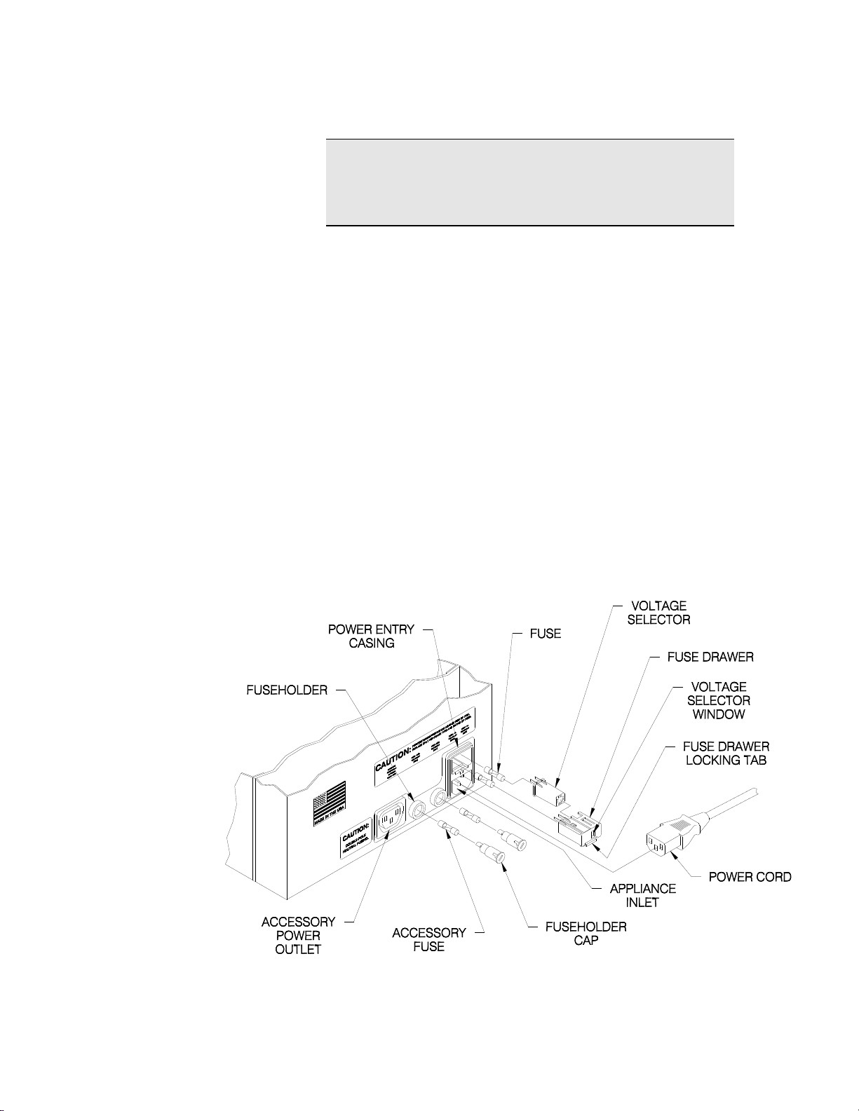
NOTE
The detachable POWER CORD may have to be
changed to match the particular power-source
output.
1. Unplug the POWER CORD.
2. Use a small screwdriver or similar tool to push up
on and release the FUSE DRAWER LOCKING
TAB.
3. Pull the FUSE DRAWER out of the POWER
ENTRY CASING.
4. Pull the VOLTAGE SELECTOR out of the FUSE
DRAWER.
5. Rotate the VOLTAGE SELECTOR until the correct
voltage is on the same side as the VOLTAGE
SELECTOR WINDOW.
6. Place the VOLTAGE SELECTOR in the FUSE
DRAWER and verify the correct voltage selection.
7. Place the FUSE DRAWER in the POWER ENTRY
CASING.
Figure 3.1 - FD 260 Power Connection
9
Page 14

3.3 Line Fuses
The FUSE DRAWER located on the non-operator
side contains two LINE FUSES. (Refer to Figure 3.1.)
The neutral and hot lines of power are fused. Both
LINE FUSES must be intact for the FD 260 to operate
properly.
CAUTION
VERIFY THAT THE LINE FUSE VALUE IS
CORRECT FOR THE VOLTAGE SETTING.
UNPLUG THE FD 260 BEFORE STARTING THIS
PROCEDURE.
Use the following instructions to verify that the LINE
FUSES installed have the proper fuse value or to
replace a blown fuse:
1. Unplug the POWER CORD.
2. Use a small screwdriver or similar tool to push up
on and release the FUSE DRAWER LOCKING
TAB.
3. Pull the FUSE DRAWER out of the POWER
ENTRY CASING. The LINE FUSES are inside.
4. Determine the proper fuse value as well as the
condition of the LINE FUSE. The fuse value is
shown on the metal tip of the LINE FUSE. The
chart below lists the selected voltage in the left
column followed by the proper fuse value in the
right column.
Selected Voltage Line Fuse Value
100V…………………….1.0A (250V time delay)
120V………………….....1.0A (250V time delay)
220V……………………..0.5A (250V time delay)
240V (or 230V)…………0.5A (250V time delay)
5. Replace the LINE FUSE if necessary. Both LINE
FUSES must be intact for the FD 260 to operate
properly.
6. Install the FUSE DRAWER in the POWER
ENTRY CASING.
10
Page 15

3.4 Accessory
Fuses
Two FUSEHOLDERS are located on the nonoperator side between the APPLIANCE INLET and
the ACCESSORY POWER OUTLET. (Refer to
Figure 3.1.) The FUSEHOLDERS hold two
ACCESSORY FUSES which protect the
ACCESSORY POWER OUTLET. As with the LINE
FUSES mentioned previously, both the neutral and
hot lines are fused. Both ACCESSORY FUSES must
be intact for the FD 260 to properly supply power to
in-line equipment.
WARNING
UNPLUG THE POWER CORD BEFORE STARTING
THIS PROCEDURE.
Use the following instructions to verify that the
ACCESSORY FUSES installed have the proper fuse
value or to replace a blown fuse:
1. Unplug the POWER CORD.
2. Use a small screwdriver or similar tool to press in
and rotate the FUSEHOLDER CAP
counterclockwise to release this cap.
3. Pull the FUSEHOLDER CAP (with the
ACCESSORY FUSE inside) out of the
FUSEHOLDER.
4. Verify the fuse value. Inspect fuses, replace if
blown.
Selected Voltage Line Fuse Value
100V…………………… 6.3A (250V time delay)
120V…………………… 6.3A (250V time delay)
220V…………………… 3.15A (250V time delay)
240V (or 230V)……….. 3.15A (250V time delay)
5. Install the ACCESSORY FUSE and the
FUSEHOLDER CAP in the FUSEHOLDER. Both
ACCESSORY FUSES must be intact for the FD
260 to properly supply power to in-line equipment.
6. Using the screwdriver, press in and turn the
FUSEHOLDER CAP clockwise to lock it.
11
Page 16

3.5 Accessory
Power Outlet
The ACCESSORY POWER OUTLET is located next
to the FUSEHOLDER on the non-operator side.
(Refer to Figure 3.1.) This outlet supplies power to
equipment running in-line with the FD 260.
Typical in-line equipment includes feeders and
labelers. Since the ACCESSORY POWER OUTLET
gets its power from the FD 260, you can control
power to in-line equipment using the FD 260’s
POWER SWITCH. Additionally, the FD 260 features
an automatic interrupt that disables the ACCESSORY
POWER OUTLET in case of a jam. The
ACCESSORY POWER OUTLET is limited to a 6.3A
maximum for 100V and 120V, and 3.15A maximum
for 220V and 240V.
3.6 Power Cord
The FD 260 comes with a three-wire POWER CORD.
The POWER CORD grounds the FD 260 when
connected to an approved three-contact electrical
outlet.
1. Plug the POWER CORD into the APPLIANCE
INLET on the non-operator side. (Refer to Figure
3.1.)
2. Plug the POWER CORD into a grounded outlet.
WARNING
TO PREVENT ELECTRICAL SHOCK, ONLY PLUG
THE POWER CORD INTO A GROUNDED OUTLET.
12
Page 17

4. CONTROLS
4.1 Power Switch
4.2 LCD Counter
Figure 4.1 - FD 260 Controls
The POWER SWITCH is located on the bottom of the
operator side panel. (Refer to Figure 4.1) Turn the
POWER SWITCH on to supply power to the FD 260.
The LCD COUNTER is located on the top of the
operator side panel. (Refer to Figure 4.1) The LCD
COUNTER displays the current number of tabbed
mail pieces fed through the FD 260. Reset the LCD
COUNTER by pressing the red button.
13
Page 18

mail piece thickness:
set lever to:
Upper feed rolls will:
from 1/8" to 1/4"
THICK
raise up
thinner than 1/8"
THIN
Lower down
4.3 Gap Adjustment
Lever
The GAP ADJUSTMENT LEVER on top of the FD
260 tabbing head. (Refer to Figure 4.1.) controls the
size of the gap between the upper and lower feed
rolls.
CAUTION
TO AVOID A JAM, ALWAYS MAKE SURE THE GAP
ADJUSTMENT LEVER IS SET CORRECTLY FOR
THE MAIL PIECES BEING TABBED.
4.4 Tab Size Switch
4.5 Control Panel
Toggle between 1.0 and 1.5 inch tabs with the power
OFF. The switch is located
to the left of the Control
Panel.
Figure 4.2 Tab Size Selector Switch
Figure 4.3 - FD 260 Control Panel
4.5.1 Tab Ready
The TAB READY light illuminates when a tab is
detected at the peel point. Stray tabs at the peel
point will also illuminate the TAB READY light.
14
Page 19

The TAB READY light also warns you of malfunctions
during tabbing by flashing as the FD 260 shuts down.
15
Page 20

4.5.2 Clear Tab
The CLEAR TAB control tells the FD 260 whether to
detect clear (and translucent) or opaque tabs.
When CLEAR TAB is toggled on, the light illuminates
and the sensor is tuned to detect clear tabs. When
CLEAR TAB is toggled off, the light doesn’t illuminate
and the sensor is tuned for opaque (paper) tabs.
NOTE
Before turning CLEAR TAB on, always remove
tabs
or debris from the peel point area.
If there are clear tabs or debris in the peel point area
when CLEAR TAB is activated, the sensor will not
correctly detect clear tabs.
If there are opaque tabs or debris in the peel point
area when CLEAR TAB is activated, the CLEAR TAB
light flashes and neither CLEAR TAB nor ON/OFF
can be activated.
4.5.3 On/Off
The ON/OFF control starts and stops tabbing.
Toggle ON/OFF so the light illuminates to begin
tabbing. Toggle ON/OFF so the light doesn’t
illuminate to stop tabbing.
Once ON/OFF is activated, you cannot change the
CLEAR TAB selection. To change the CLEAR TAB
selection, Toggle ON/OFF off to stop tabbing, remove
tabs and debris from peel point area, turn the
POWER SWITCH off and on again and make your
new CLEAR TAB selection.
NOTE
Once ON/OFF is activated, the CLEAR TAB
selection is locked. Even if you stop tabbing by
toggling ON/OFF off, the CLEAR TAB selection
cannot be changed.
16
Page 21

5. FEEDING DEVICES
5.1 Placing The FD
260 In-Line
To operate the FD 260 in-line with your feeding
device, place the output end of the feeding device
next to the input end of the FD 260. Leave about an
1
/8" gap between the machines. Align machines to
place tabs where desired on the mail pieces.
The gap between the feeding device and the FD 260
may need adjusting if the mail pieces are curled or
rigid. If the mail pieces’ leading edge curls up, the
gap should be larger than 1/8" to allow the curled edge
to come down before entering the FD 260. If the
leading edge curls down, the gap should be as small
as possible, so the mail pieces will not fall between
the two machines. A rigid mail piece may require a
larger gap if it hits the bracket above the FD 260
PAPER PATH.
NOTE
Turn on the FD 260 before turning on any feeding
device. If the FD 260 is not turned on first,
it will not accept the fed mail pieces.
NOTE
Some equipment, when run in-line with the FD
260, requires a stand to raise it to the level of the
FD 260. When ordering additional equipment,
specify which machine you plan to operate in-line
with the FD 260.
17
Page 22

5.2 FORMAX
FD 260-10
Feeder
The Formax FD 260-10 Feeder is an automatic,
variable speed Feeder. Load a stack of mail pieces
into its feed tray to automatically feed one mail piece
after another into the FD 260. Figure 5.1 illustrates
the FD 260-10 in-line with the FD 260.
Figure 5.1 - The Formax FD 260-10 Feeder in-line with the FD 260 Tabber.
18
Page 23

6. OPERATION
6.1 Threading Tabs
WARNING
KEEP LOOSE CLOTHING, TIES, SCARVES AND
HAIR AWAY FROM ALL MOVING PARTS. DO NOT
PLACE FINGERS OR TOOLS BETWEEN OR NEAR
MOVING PARTS.
To thread tabs:
1. Remove 12 tabs from the leading edge of the tab
strip.
2. Remove the outside RUBBER RING, pull down
the SHELF and remove both TAB ROLL
ADAPTERS from the TAB SPINDLE. (Refer to
Figure 6.1.)
Figure 6.1 – Threading Tabs
19
Page 24

3. Insert one or both TAB ROLL ADAPTERS into the
core of the TAB ROLL. The TAB ROLL width may
allow only one TAB ROLL ADAPTER to fit in the
TAB ROLL.
4. Pull the SHELF down. Place the TAB ROLL
ADAPTER (rim away from you) with the TAB
ROLL attached on the TAB SPINDLE. (Refer to
Figure 6.2.)
NOTE
The tab strip must pull from the bottom of the TAB
ROLL toward the input end -- with the tabs on the
bottom of the tab strip -- facing the FEED TRAY.
Figure 6.2 - Threading Tabs
20
Page 25

5. Center the TAB ROLL between the two GUIDES
on the SHELF. Slide these GUIDES against the
TAB ROLL. Place the RUBBER RING (removed
in step 2) on the TAB SPINDLE. Press both
RUBBER RINGS against the TAB SPOOL
ADAPTER.
6. Pull up the LATCH on the PEEL PLATE
ASSEMBLY and lift the PEEL PLATE ASSEMBLY
out of its slot. (Refer to Figure 6.2.)
7. Thread the backing paper over the DANCER
ROLL. (Refer to Figure 6.2.)
8. Thread the backing paper over the BACKING
PAPER GUIDES. Slide the BACKING PAPER
GUIDES against the backing paper. (Refer to
Figure 6.2.) There are notches for 1.125" (1"
tab) and 13/4" (1.5" tab) wide backing paper, but
you can use any backing paper between 1" and
13/4" wide. The BACKING PAPER GUIDES will
stay in place if there are no notches for the
backing paper width.
9. Thread 6-8" of backing paper away from the input
end and place the PEEL PLATE ASSEMBLY in its
slot. Use the PEEL PLATE ASSEMBLY to push
the backing paper toward the peel point. Press
down and lock the LATCH. (Refer to Figure 6.2.)
At this point, the backing paper should be over the
BACKING PAPER GUIDES, under the PEEL
PLATE ASSEMBLY and up towards the TAKE-UP
SPINDLE.
10. Thread the backing paper over the DRIVE ROLL.
(Refer to Figure 6.2.)
11. Turn the THREADING KNOB counterclockwise
and thread the backing paper between the NIP
ROLL and the THREADING KNOB metal bar.
(Refer to Figure 6.2.) When you release the
THREADING KNOB, the gap between the DRIVE
ROLL and the NIP ROLL closes.
12. Remove the CLIP from the TAKE-UP SPINDLE,
wrap the backing paper around the TAKE-UP
SPINDLE and secure the CLIP on the backing
paper. (Refer to Figure 6.1.)
13. Remove any tabs that have peeled under the
PEEL PLATE. Reach them through the
INSPECTION WINDOW on the input end.
21
Page 26

6.2 Feeding
Mail Piece
1. Select Tab Size
2. Turn FD 260’s POWER SWITCH on.
NOTE
Turn the FD 260’s POWER SWITCH on before
turning on the feeding device. If the FD 260 is not
turned on first, it will not accept the mail pieces.
3. Toggle ON/OFF so light does not illuminate.
4. Set the FD 260’s GAP ADJUSTMENT LEVER to
thick for mail pieces 1/8" to 1/4" thick, or to thin for
mail pieces thinner than 1/8".
4. Place a stack of mail pieces open edge first in the
feeding device. Feed several mail pieces. Adjust
the feeding speed until the mail pieces feed one at
a time with a consistent rhythm.
6.3 Tabbing Mail
Pieces
1. Make sure tabs are threaded correctly and peel
point area is clear.
2. Turn the POWER SWITCH on.
CAUTION
TO AVOID A JAM, TURN THE FD 260 ON BEFORE
TURNING ON THE FEEDING DEVICE.
3. Make CLEAR TAB selection. Toggle CLEAR TAB
on for clear and translucent tabs. Toggle CLEAR
TAB off for opaque tabs.
4. Toggle ON/OFF so the TAB READY light
illuminates.
NOTE
Once the ON/OFF light illuminates, you cannot
change the CLEAR TAB selection.
22
Page 27

Figure 6.3 – FD 260 Controls
5. Make sure the GAP ADJUSTMENT LEVER is set
properly.
6. Begin feeding mail pieces into the FD 260. The TAB
READY light will illuminate every time a tab reaches the
application point.
7. Make sure each mail piece is tabbed. Re-align the
machines if the tabs are not being placed in the desired
position on the mail pieces. (Also refer to Section 5.1.)
TIP
When finishing a tabbing job, remove the last tab
at the peel point to make the next tabbing job start
off easier:
1. Toggle ON/OFF so light is off.
2. Feed one mail piece through the FD 260
to
remove the last tab at the peel point.
23
Page 28

6.4 Removing
Waste Backing
Paper
Figure 6.4 - Removing Waste Backing Paper
1. Tear the waste backing paper, leaving enough to
reach and wrap around the TAKE-UP SPINDLE.
2. Pull the waste backing paper off the TAKE-UP
SPINDLE.
3. Remove the CLIP from the center of the waste
backing paper.
4. Place backing paper over the TAKE-UP SPINDLE
ASSEMBLY from the input end.
5. Secure the backing paper to the SPINDLE with
the CLIP.
TIP
Have a few extra CLIPS on hand
as they are easy to lose.
24
Page 29

7. MAINTENANCE
7.1 General Cleaning
& Clearing
Your FD 260 will need regular cleaning. How often
you’ll need to clean the FD 260 depends on the
amount of paper dust your mail pieces generate.
Wipe surface dust or debris from the FD 260 with a
damp cloth as necessary.
7.1.1 Removing Tabs &
Debris From Peel Point
Area
Periodically check for peeled tabs stuck on or near
the bottom of the PEEL PLATE. You can see this
area by looking through the INSPECTION WINDOW
on the input end, below the threading path.
If you use clear tabs, you must remove any tabs stuck
in the entire PEEL PLATE area before activating
CLEAR TAB.
To remove tabs and debris from peel point area:
WARNING
DO NOT PLACE FINGERS OR TOOLS BETWEEN
OR NEAR MOVING PARTS.
1. Turn the POWER SWITCH off.
2. Reach through the INSPECTION WINDOW and
remove all tabs and debris.
25
Page 30

7.2 Replacing a
Fuse
7.2.1 Line Fuse
When one or both LINE FUSES are blown, the FD
260 will appear to have no power and the LINE FUSE
must be replaced.
WARNING
UNPLUG THE POWER CORD BEFORE OPENING
THE FUSE DRAWER.
To replace a LINE FUSE:
1. Use a small screwdriver or similar tool to push up
on the FUSE DRAWER LOCKING TAB to release
this locking tab. (Refer to Figure 7.1.)
2. Pull the FUSE DRAWER out of the POWER
ENTRY CASING. (Refer to Figure 7.1.)
Figure 7.1 – Replacing a Line Fuse
26
Page 31

3. Inspect the FUSES; look for blackened glass,
melted wire or a disconnected wire between the
ends of the tube. If you find any of these
problems in either FUSE, that FUSE is blown and
must be replaced.
4. Pull the blown FUSE from its slot.
WARNING
REPLACE ONLY WITH SAME TYPE AND RATING
OF FUSE. (REFER TO CHART BELOW.)
Selected Voltage Line Fuse Value
100V…………………….1.0A (250V time delay)
120V………………….....1.0A (250V time delay)
220V……………………..0.5A (250V time delay)
240V (or 230V)…………0.5A (250V time delay)
5. Place the new FUSE into the same slot.
7.2.2 Accessory
Fuse
6. Install the FUSE DRAWER. (Refer to Figure 7.1.)
When one or both ACCESSORY FUSES are blown,
the ACCESSORY POWER OUTLET and the
machine plugged into this outlet lose power.
WARNING
UNPLUG THE POWER CORD BEFORE OPENING
THE FUSE DRAWER.
To replace an ACCESSORY FUSE:
1. Use a small screwdriver or similar tool to press in
and slightly rotate the FUSEHOLDER CAP
counterclockwise. (Refer to Figure 7.1.)
2. Inspect the FUSE; look for blackened glass,
melted wire or a disconnected wire between the
ends of the tube. If you find any of these
problems in the FUSE, it is blown and must be
replaced. If the first FUSE is fine, repeat steps 1
and 2 for the second FUSE.
3. Pull the blown FUSE from its slot.
27
Page 32

WARNING
REPLACE ONLY WITH SAME TYPE AND RATING
OF FUSE. (REFER TO CHART BELOW.)
Selected Voltage Line Fuse Value
100V…………………… 6.3A (250V time delay)
120V…………………… 6.3A (250V time delay)
220V…………………… 3.15A (250V time delay)
240V (or 230V)……….. 3.15A (250V time delay)
4. Place the new FUSE into the same slot.
5. Install the FUSEHOLDER CAP into the
FUSEHOLDER. (Refer to Figure 7.1.)
28
Page 33

Trouble
Cause
Solution
1. Nothing works.
Power switch is not on.
Turn power switch on.
Power cord is
damaged or not
plugged into proper
outlet.
Replace power cord if
damaged or plug into
proper outlet if
necessary.
Outlet does not have
power present.
Check circuit source
for a blown fuse or
circuit breaker.
2. CLEAR TAB light
flashes 8-10
seconds after
CLEAR TAB is
turned on.
Sensor is blocked.
Remove all tabs and
debris from peel point
area. Tune sensor.
Refer to Section
9.1.2.
3. No tabs on mail
pieces.
TAB READY light is
off. Peel point is free
of tabs and debris.
Toggle ON/OFF until
light illuminates.
4. FD 260 shuts
down. TAB
READY light
starts flashing.
Sensor could not find
tab during the pre-set
time.
Tune sensor. Refer to
Section 9.1.2.
5. Not tabbing -TAB READY light
remains on,
multiple tabs
peeled.
Incorrect CLEAR TAB
selection.
Make CLEAR TAB
selection for tabs
being run. Refer to
Section 9.1.2.
6. Not tabbing -TAB READY light
is on but no tabs
at peel point.
Sensor is blocked by
debris.
Remove debris from
the peel point area
through the inspection
window.
8. TROUBLESHOOTING
REMOVING, ADJUSTING OR REPAIRING ANY
8.1
Troubleshooting
Chart
WARNING
UNPLUG THE POWER CORD BEFORE
PARTS IN THE
FD 260.
29
Page 34

Trouble
Cause
Solution
7. FD 260 stops.
Power entry fuse is
blown.
Replace blown line
fuse. Refer to Section
3.3.
FD 260 keeps blowing
fuses after you replace
them.
Contact authorized
Formax dealer.
Mail piece has jammed
in machine.
Clear the jam. Refer
to Section 9.1.3.
Backing paper has torn
before the drive roll.
Thread tabs from that
point on. Refer to
Section 9.1.4.
8. Feeding stops.
Accessory fuse is
blown.
Replace blown
accessory fuse. Refer
to Section 3.4. If the
fuse is not blown,
refer to your feeding
device manual.
9. Backing paper
slack.
Backing paper is
threaded under the
drive roll.
Re-thread tabs. Refer
to Section 6.1.
10. Tabbing
incorrectly
Peel plate assembly is
not latched.
Insert and latch peel
plate assembly.
11. Multiple tabs on
mail piece.
Incorrect CLEAR TAB
selection.
Make CLEAR TAB
selection for tabs
being run. Refer to
Section 9.1.2.
Incorrect Tab Size
setting
Turn Power Off,
change tab size
switch.
12. Tab placement is
inconsistent.
Mail pieces are feeding
crooked.
Make sure mail pieces
feed straight into FD
260. Refer to Section
9.2.1.
Backing paper has torn
after the drive roll.
Re-thread backing
paper from drive roll.
Refer to Section
9.1.4.
13. Tab fold is
uneven.
Peel plate position
needs adjustment.
Adjust peel plate
position. Refer to
Section 9.2.2.
Tab Size Wrong
Power Off, select tab
size
30
Page 35

Trouble
Cause
Solution
14. Tab fold is off
mail piece.
Sweep position needs
adjustment.
Contact authorized
Formax dealer.
15. Leading edge of
mail piece tears
at the tab.
Sweep position needs
adjustment.
Mail pieces are poorly
folded.
Mail pieces are too
thin.
Contact authorized
Formax dealer.
16. Mail pieces jam
upon entering
FD 260.
Sweep position
requires adjustment.
Contact authorized
Formax dealer.
Sweep is reversed.
Slide plastic ruler
along feed tray to
reverse sweep.
17. Tab does not
fold, one tab is
folded on
multiple mail
pieces and/or
some mail pieces
are not tabbed.
Feeding device is too
fast.
Reduce speed of
feeding device until
tabs are being applied
correctly.
18. Difficulty
running
translucent tabs
Translucent tabs
typically run on the
Clear Tab setting
See Section 9.1.2 to
clear machine and
turn Sense Clear on.
19. Backing Paper
jam
With 1.5 inch tads poor
peel bar adjustment
The Peel Bar needs to
be straight. Top and
bottom edges must be
parallel. Check
carefully and correct
as necessary.
31
Page 36

9. CORRECTING TABBING PROBLEMS
9.1 No Tabs
Applied to
Mail Pieces
9.1.1 Sensor
Could Not Detect
Tab
At start-up, when the ON/OFF light is illuminated, the
tab strip advances until the sensor detects a tab at
the peel point. If no tab is detected, toggle ON/OFF
until the TAB READY light illuminates.
Figure 9.1 – FD 260 Control Panel
32
Page 37

9.1.2 Sensor Is Not
Tuned for Clear
Tabs
If the sensor is not tuned for clear tabs, one of the
following problems may occur:
TAB READY light remains on, but there is more
than one tab at the peel point.
TAB READY light flashes and the tab strip stops
advancing after peeling several clear tabs at the
peel point.
If you experience either of these problems, tune the
sensor for clear tabs:
WARNING
DO NOT PLACE FINGERS OR TOOLS BETWEEN
OR NEAR MOVING PARTS.
1. Turn the POWER SWITCH off.
2. Remove any tabs and debris from the peel point
area through the INSPECTION WINDOW on the
input end, below the threading path.
CAUTION
IF ALL TABS AND DEBRIS ARE NOT REMOVED
FROM THE PEEL POINT AREA BEFORE CLEAR
TAB IS ACTIVATED, THE SENSOR’S DEFINITION
OF CLEAR TABS WILL CHANGE AND CLEAR
TABBING WILL BE PREVENTED.
3. Toggle CLEAR TAB off.
4. Toggle CLEAR TAB on.
5. Toggle ON/OFF until a tab advances to the peel
point and the TAB READY light illuminates.
33
Page 38

9.1.3 Mail Piece
Jam
Mail pieces usually jam at the feed rolls or between
the belts and metal rolls at the end of the FEED
TRAY. Mail pieces can jam if the SWEEP is too high.
Mail pieces can be blocked if the SWEEP is not bent
on the FEED TRAY. If jamming is caused by the
SWEEP, contact an authorized Formax dealer for
service.
Figure 9.2 – Clearing Jammed Mail Pieces
To clear mail pieces from the feed rolls:
WARNING
DO NOT PLACE FINGERS OR TOOLS BETWEEN
OR NEAR MOVING PARTS.
1. Turn the POWER SWITCH off.
2. Pull the jammed mail pieces out in the direction
they feed through the FD 260.
34
Page 39

CAUTION
PULLING MAIL PIECES IN THE OPPOSITE
DIRECTION THAT THEY MOVE THROUGH THE FD
260 MAY DAMAGE THE SWEEP OR MOVE IT OUT
OF POSITION.
3. If you cannot reach the jammed mail pieces,
continue through the following instructions.
4. Set the GAP ADJUSTMENT LEVER to thick, if it
is set for thin. (Refer to Figure 9.2.)
5. Push the FOAM ROLL ASSEMBLY toward the
end with the spring attached. Pull out the other
end, as you push in the spring end. Make sure the
other end clears the side frame. (Refer to Figure
9.2.)
6. Remove any mail pieces jammed at the feed rolls.
7. Push the spring-loaded end of the FOAM ROLL
ASSEMBLY in its hole in the non-operator side
panel. Place the other end of the FOAM ROLL
ASSEMBLY into the d-hole in the operator side
frame. (Refer to Figure 9.2.)
8. Set the GAP ADJUSTMENT LEVER to thin if you
are tabbing mail pieces thinner than 1/8".
To remove mail pieces jammed between the belts
and metal rolls at the end of the FEED TRAY:
WARNING
DO NOT PLACE FINGERS OR TOOLS BETWEEN
OR NEAR MOVING PARTS.
1. Turn the POWER SWITCH off.
2. Pull the mail pieces from the feed tray. Make sure
all belts are centered on the metal rolls before you
resume tabbing.
35
Page 40

9.1.4 Torn Backing
Paper
If the backing paper tears before the drive roll, the FD
260 will stop tabbing but continue feeding. To start
tabbing:
WARNING
DO NOT PLACE FINGERS OR TOOLS BETWEEN
OR NEAR MOVING PARTS.
1. Turn the POWER SWITCH off.
2. Thread the FD 260 from the point where the
backing paper tore. (Refer to Section 6.1.)
NOTE
When backing paper is pulled, tabs will peel at the
PEEL PLATE until pulling is stopped.
3. Remove any tabs or debris from the peel point
area through the INSPECTION WINDOW on the
input end, below the threading path.
4. Turn the POWER SWITCH on.
5. Toggle ON/OFF until a tab advances to the peel
point and the TAB READY light illuminates.
If the backing paper tears after the drive roll, the
backing paper may fall away from the FD 260 and
tabbing will continue. If the backing paper wraps
around rolls in the threading path, tabbing may
continue, but tab placement may not be accurate. To
continue tabbing accurately:
WARNING
DO NOT PLACE FINGERS OR TOOLS BETWEEN
OR NEAR MOVING PARTS.
1. Turn the POWER SWITCH off.
2. Secure the backing paper around the TAKE-UP
SPINDLE with the CLIP. You may need to pull the
backing paper a little to reach the TAKE-UP
SPINDLE.
36
Page 41

NOTE
When backing paper is pulled, tabs will peel at the
PEEL PLATE until pulling is stopped.
3. Remove any tabs stuck at the PEEL PLATE.
Reach the tabs through the INSPECTION
WINDOW on the input end, below the threading
path.
4. Turn the POWER SWITCH on.
5. Toggle ON/OFF until a tab advances to the peel
point and the TAB READY light illuminates.
9.1.5 Incorrect
Threading
Threading a tab strip incorrectly can prevent tabbing.
Two examples are listed below.
PEEL PLATE ASSEMBLY is not latched. The
backing paper will pull the PEEL PLATE assembly
out of its slot, tabs will peel in the wrong place,
and the PEEL PLATE assembly will block any mail
pieces entering the FD 260.
Backing paper is threaded under the DRIVE
ROLL. The backing paper will pull backward and
no tabs will peel.
Refer to Section 6.1 for instruction on threading tabs.
37
Page 42

9.2 Poor Tab
Placement Or
Appearance
9.2.1 Tab
Placement Is
Inconsistent
If tab placement on mail pieces varies during the
same run, check to see if mail pieces are feeding
straight. Make sure the paper guides on your feeding
device are set against the sides of the stack of mail
pieces. If mail pieces can move sideways between
the paper guides, they will not feed straight.
To check your tab placement:
1. Hold a stack of tabbed mail pieces. Make sure all
edges are straight and even, and all tabs are on
the same side.
2. Look at the tabbed side of the stack. If the tabs
do not form a straight line down the stack, the mail
pieces are moving sideways as they enter the FD
260.
3. Set paper guides correctly and securely on the
feeding device.
9.2.2 Tab Fold Is
Uneven
If tabs are not wrapped evenly around mail pieces,
(Figure 9.3) either the PEEL PLATE position needs
adjustment. or the Tab Size switch setting does not
match the tabs being used. Power Off and set tab
switch correctly.
Figure 9.3 – Both Sides of One Mail Piece
38
Page 43

Figure 9.4 – Input End
To adjust the PEEL PLATE position:
WARNING
DO NOT PLACE FINGERS OR TOOLS BETWEEN
OR NEAR MOVING PARTS.
1. Turn the POWER SWITCH off.
2. Remove the PEEL PLATE ASSEMBLY.
3. Loosen the SCREWS on the PEEL PLATE
ASSEMBLY with a short, small blade screwdriver.
(Refer to Figure 9.4.)
4. Slightly move the PEEL PLATE up or down on the
PEEL PLATE BRACKET. (Refer to Figure 9.4.)
Move the PEEL PLATE up to place a larger
portion of the tab on the top side of the mail piece.
Move the PEEL PLATE down to place a larger
portion of the tab on the bottom side of the mail
piece.
5. Tighten the SCREWS you loosened in step 3 to
secure the PEEL PLATE to the PEEL PLATE
BRACKET.
6. Replace the PEEL PLATE ASSEMBLY.
7. Turn the POWER SWITCH on.
8. Feed a few mail pieces through the FD 260 and
observe the tab placement. Repeat until the tab
has equal portions on the top and bottom of the
mail pieces.
39
Page 44

9.2.3 Tab Fold Is
Off Mail Piece –
Tab Is Tenting
If tabs fold too early so the tab fold is not on the mail
piece, the SWEEP needs adjusting. If the fold
resembles Figure 9.5, the SWEEP position is too
high. If the fold resembles Figure 9.6, the SWEEP
position is too low. The SWEEP is a thin piece of
white plastic that helps fold the tab onto the mail
pieces. It extends below the bottom of the PEEL
PLATE. Adjusting the SWEEP will correct the fold
but should only be done by a trained service
professional.
Figure 9.5 - Sweep Position Too High
Figure 9.6 - Sweep Position Too Low
40
Page 45

Tabs are made of different materials and will fold
differently with the same SWEEP position. For
example, paper tabs may fold differently than foil
tabs. Colored tabs may fold differently than white
tabs because ink adds moisture and density. Expect
some “tenting” with perforated tabs. Perforated tabs
tend to fold on the perf independent of PEEL PLATE
position.
The factory pre-set SWEEP position is standard and
works with most tabs. If your tabs fold too early or too
late, the SWEEP position must be adjusted. Do not
attempt this procedure. Contact an authorized
FORMAX dealer for service.
9.2.4 More Than
One Clear Tab On
Mail Piece
The FD 260 may place more than one clear tab on a
mail piece if the sensor is not tuned for clear tabs. To
correct this, tune the sensor for clear tabs. Refer to
Section 9.1.2.
41
Page 46

10. SERVICE
10.1 Service
10.2 Repacking
Instructions
If any problems occur with this equipment or if you
need assistance installing or operating your FD 260
contact an authorized FORMAX dealer.
If it is necessary to ship your FD 260 to your
authorized Formax dealer for service, pack it in the
original shipping container and packaging material. If
the original container is not available, the FD 260
should be carefully packed so that it will not be
damaged in transit.
When calling for service, have your FD 260’s serial
number handy.
NOTE
If the FD 260 is packed correctly, your Shipping
Carrier is liable for any damages that occur during
shipping.
Use the following instructions to pack the FD 260 with
commercially available materials.
1. Double wrap the machine in heavy plastic.
2. Use a heavy duty, double-walled container of 350pound test material.
3. Surround the FD 260 on ALL sides with at least 4
to 5 inches of shock absorbing packaging
material. This will provide firm cushioning and
prevent movement inside the container.
4. Seal the top and bottom of the shipping container
with strong tape or banding material.
5. Clearly and legibly mark the shipping container
FRAGILE.
6. Contact your authorized Formax Dealer.
42
 Loading...