

Page 1

FD 2092 / FD 2082
®
AutoSeal
12/2007
OPERATORS MANUAL
FIRST EDITION
Page 2

TABLE OF CONTENTS
2092 DESCRIPTION / SPECIFICATIONS 1
2082 DESCRIPTION / SPECIFICATIONS 2
ASSEMBLY 3
Conveyor Assembly 3
Folder Assembly 4
Control Panel 7
2092 Power Hookup 8
2082 Power Hookup 9
OPERATION 10
2092 Operation
Squaring 10
Vacuum Feed Sheet Separator 10
Horizontal Separator Adjustment 11
Feeding Paper 11
Bleeder Valve (Vacuum Adjustment) 12
2082 Operation
Form Set-up Procedure 13
Form Set -Up Procedures With Optional Imprinter 15
Normal Loading 15
Burster Operating Hints 16
Fold Plates 16
Roller Caliper Set-Up 17
Safety Covers 18
Fault Detectors 18
DAILY MAINTENANCE 19
General Cleaning 19
Fold Roller Cleaning 19
Sealer Roller Cleaning 19
TROUBLESHOOTING 20
TEST SHEET 23
Page 3
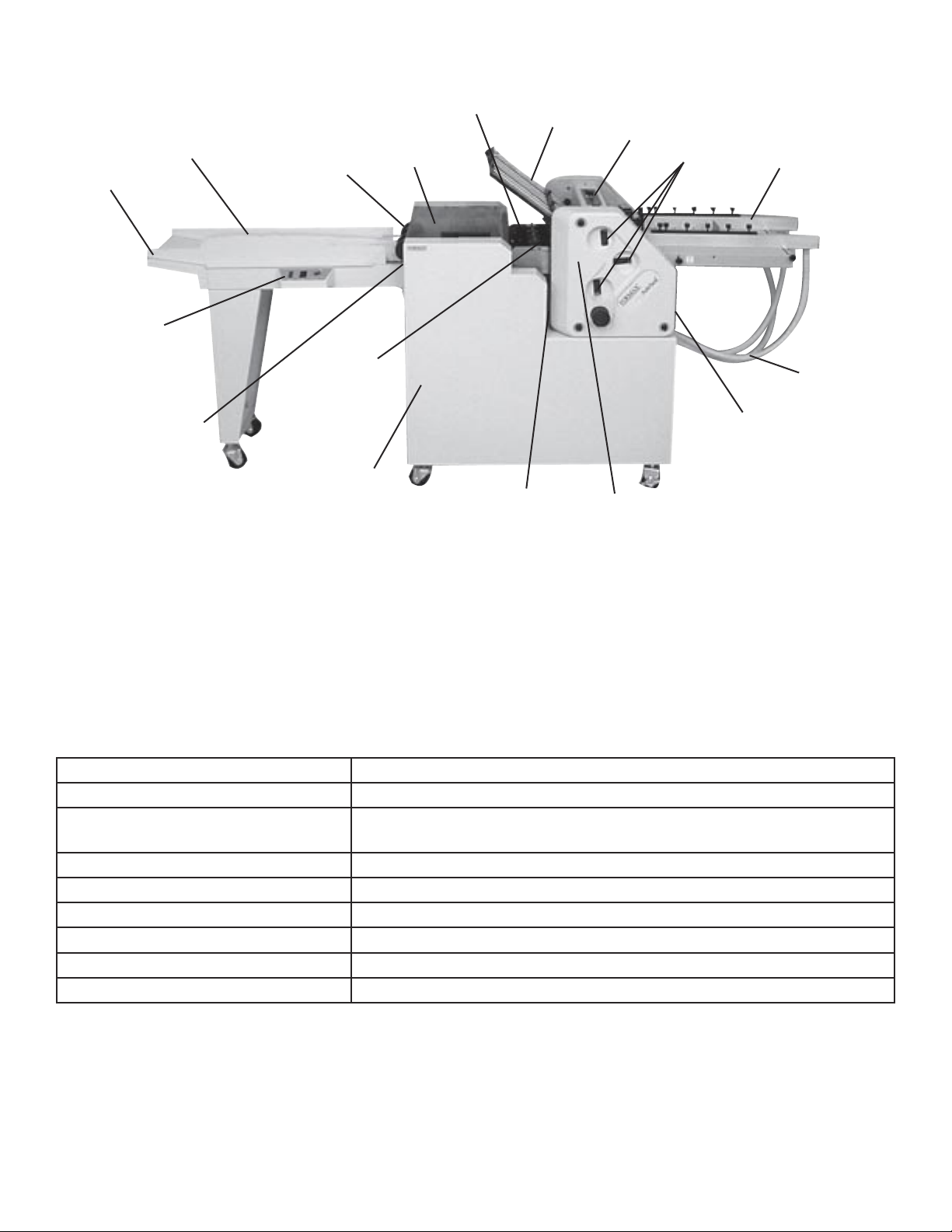
2092 DESCRIPTION
Conveyor
nip wheels
Folder Safety
Cover
Conveyor
Extension
Conveyor
Control Panel
Conveyor
8-ball
transport deck
Sealer safety
cover
Upper fold plate
Folder
Control Panel
Calipers
Infeed table
Folder Air and
vacuum hoses
Sealer power
switch
Sealer housing
and folder stand
Folder power
switch
Folder
Lower Fold plate
FUNCTION
The 2092 folds and seals pressure sensitive forms with pre-applied glue lines into mail ready pieces. Numerous
folds using several different paper sizes can be processed to meet your needs. For confi gurations and paper
sizes see specifi cations.
SPECIFICATIONS
Dimensions 2092: 98” L x 23” W x 51” H (249 L x 84 W x 129.5 H cm)
Paper thickness 20-110 lb. Index
Fold Styles Single, standard letter “C”, accordion “Z”, double parallel, brochure,
half & custom folds
Paper loading capacity 350 Sheets 24# (90 gsm)
Processing speed Up to 30,000 sheets/hr.
Duty Cycle 400,000 monthly
Paper Size 4”-11”W x 6” - 17”L (101-279W x 152-508 L mm)
Weight Approx 500 lbs. (227 kg)
Power supply 220 volt single phase, 20 Amp
1
Page 4
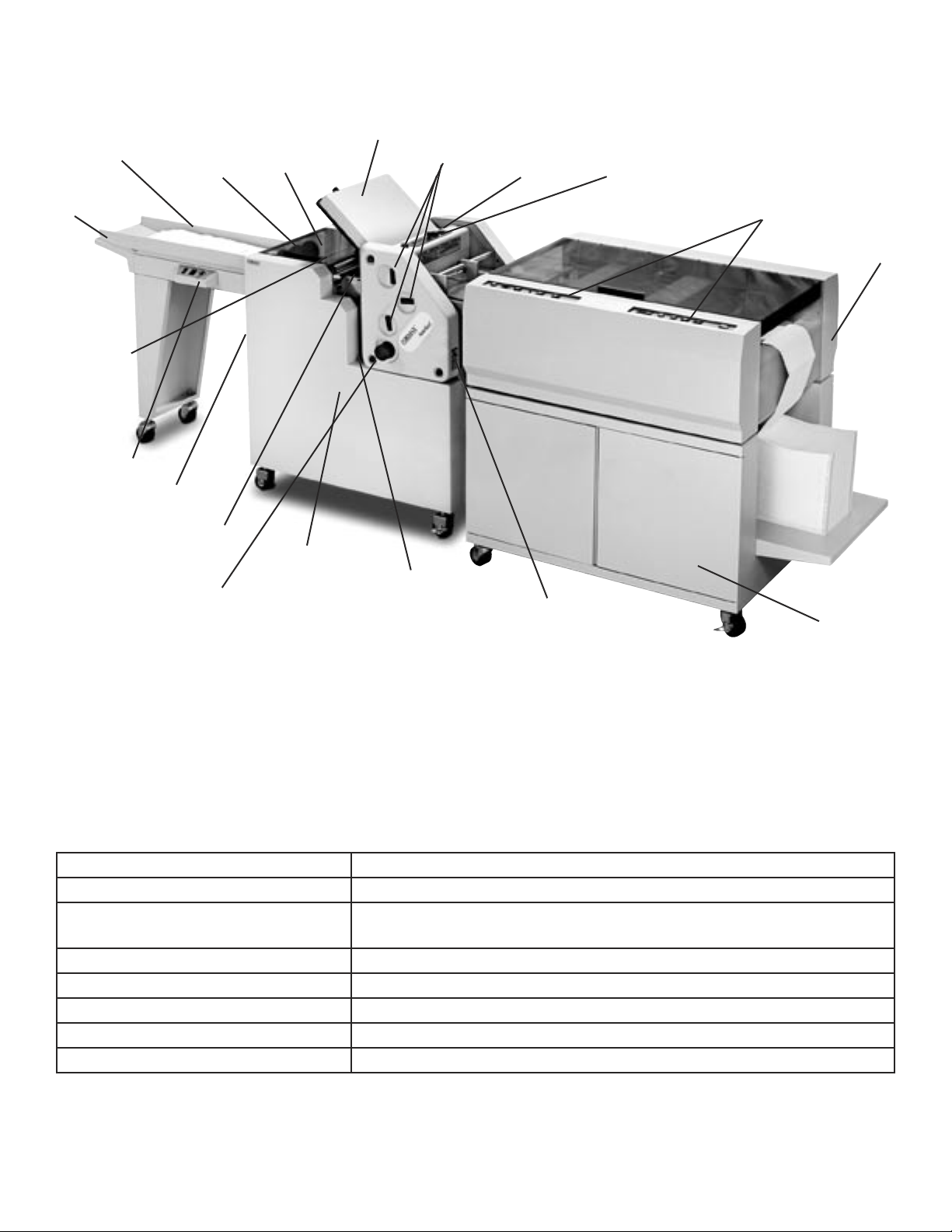
2082 DESCRIPTION
Upper Fold Plate
Conveyor
Conveyor
Extension
Folder Safety
Cover
Conveyor
Control Panel
Sealer power
switch
Conveyor
Nip Wheels
8-ball
transport deck
Manual feed
knob
Sealer Safety
Cover
Sealer housing
and folder stand
Calipers
Folder power
switch
Folder
Lower Fold plate
FUNCTION
The 2082 separates, folds, and seals continuous pressure sensitive forms with pre-applied glue lines into mail
ready pieces. Numerous folds using several different paper sizes can be processed to meet your needs. For
configurations and paper sizes see specifications.
Folder
Control Panel
Burster Controls
Burster
Base
Burster
SPECIFICATIONS
Dimensions 2082: 133” L x 33” W x 51” H (338 L x 58.5 W x 129.5 H cm)
Paper thickness 20-110 lb. Index
Fold Styles Single, standard letter ”C”, accordion “Z”, double parallel, brochure,
half & custom folds
Processing speed Up to 30,000 sheets/hr.
Duty Cycle 400,000 monthly
Paper Size 4”-11”W x 6” - 17”L (101-279W x 152-508 L mm)
Weight Approx 1000 lbs. (454 kg)
Power supply 220 volt single phase, 20 Amp
2
Page 5
ASSEMBLY
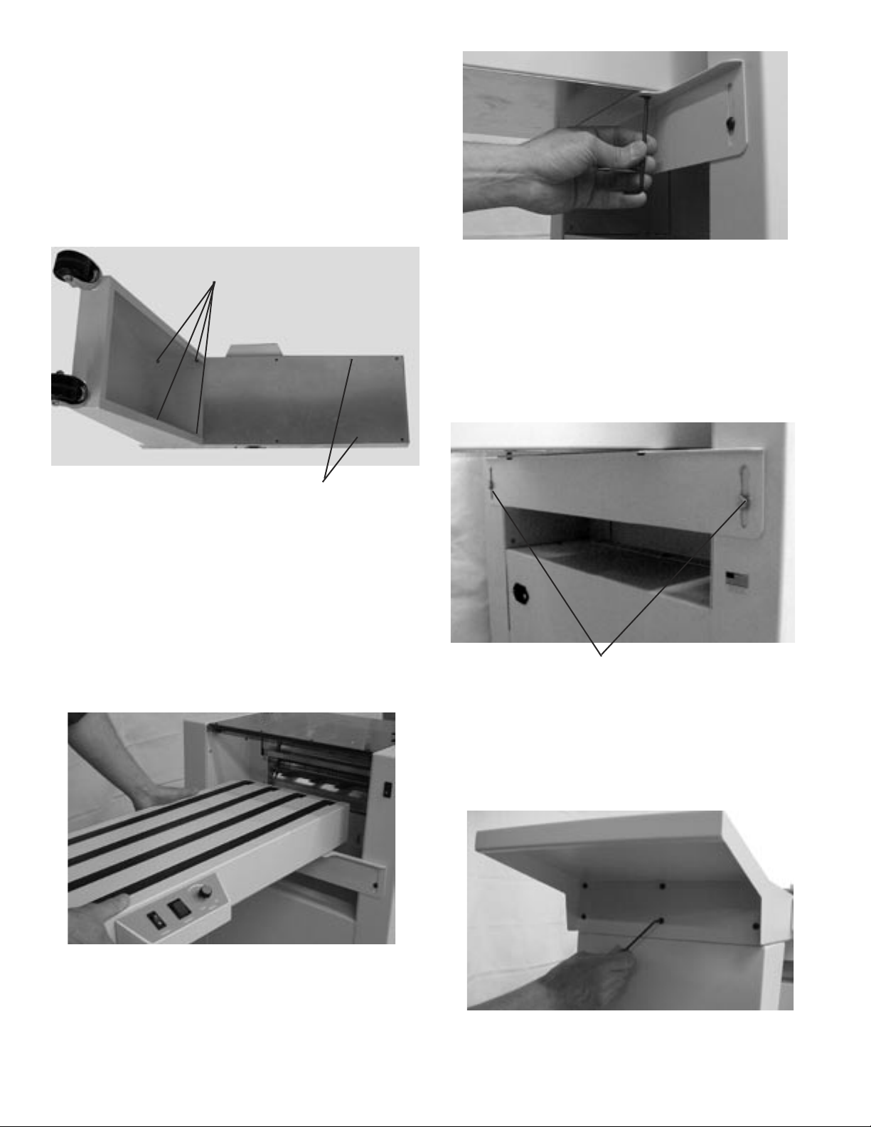
Steps for assembling the conveyor:
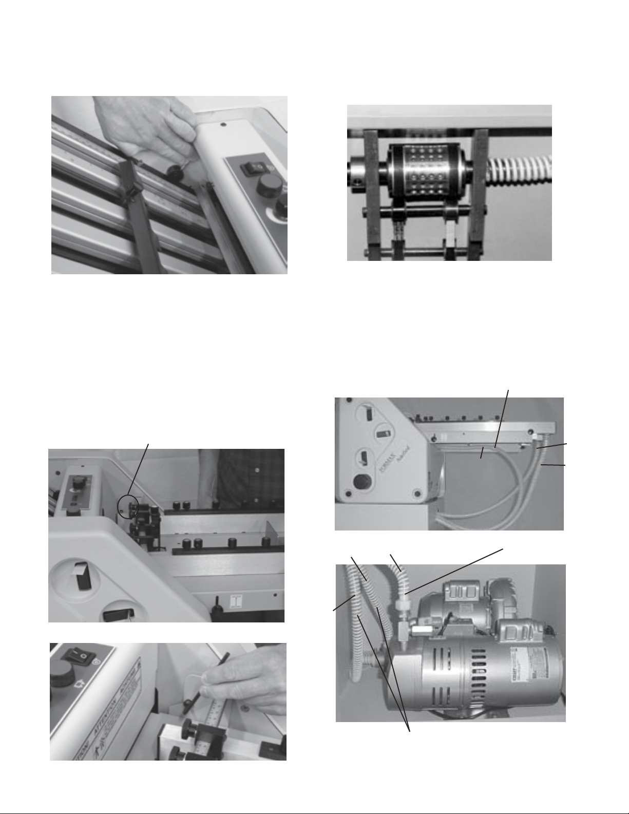
1. Turn conveyor over and remove the four screws to
the far left of the control panel with a 3/8” allen wrench.
Then attach the conveyor leg using the same four
screws (Fig 1).
Step 1
Fig 4
5. Once the conveyor is securely mounted, the bracket
can be adjusted up or down to level the conveyor.
Loosen the allen screws and slide up or down and
retighten (Fig 5).
Fig 1
Step 2
2. With the conveyor still turned over remove the
second to last set of screws that are located to the
right of the control panel (These screws will be used to
attach the conveyor to the mounting bracket) (Fig1).
3. Turn the conveyor to its upright position and roll
it up to the sealer so that holes on the underside of
the conveyor line up with the holes in the mounting
bracket. The conveyor should fit up tight against the
sealer outfeed (Fig 2).
Fig 5
Step 5
6. Attach conveyor extension to the end of the
conveyor using the six 3/8” allen screws provided
(Fig 6).
Fig 2
4. Secure the conveyor to the mounting bracket
using the two screws removed form the bottom of the
conveyor (Fig. 4).
Fig 6
3
Page 6
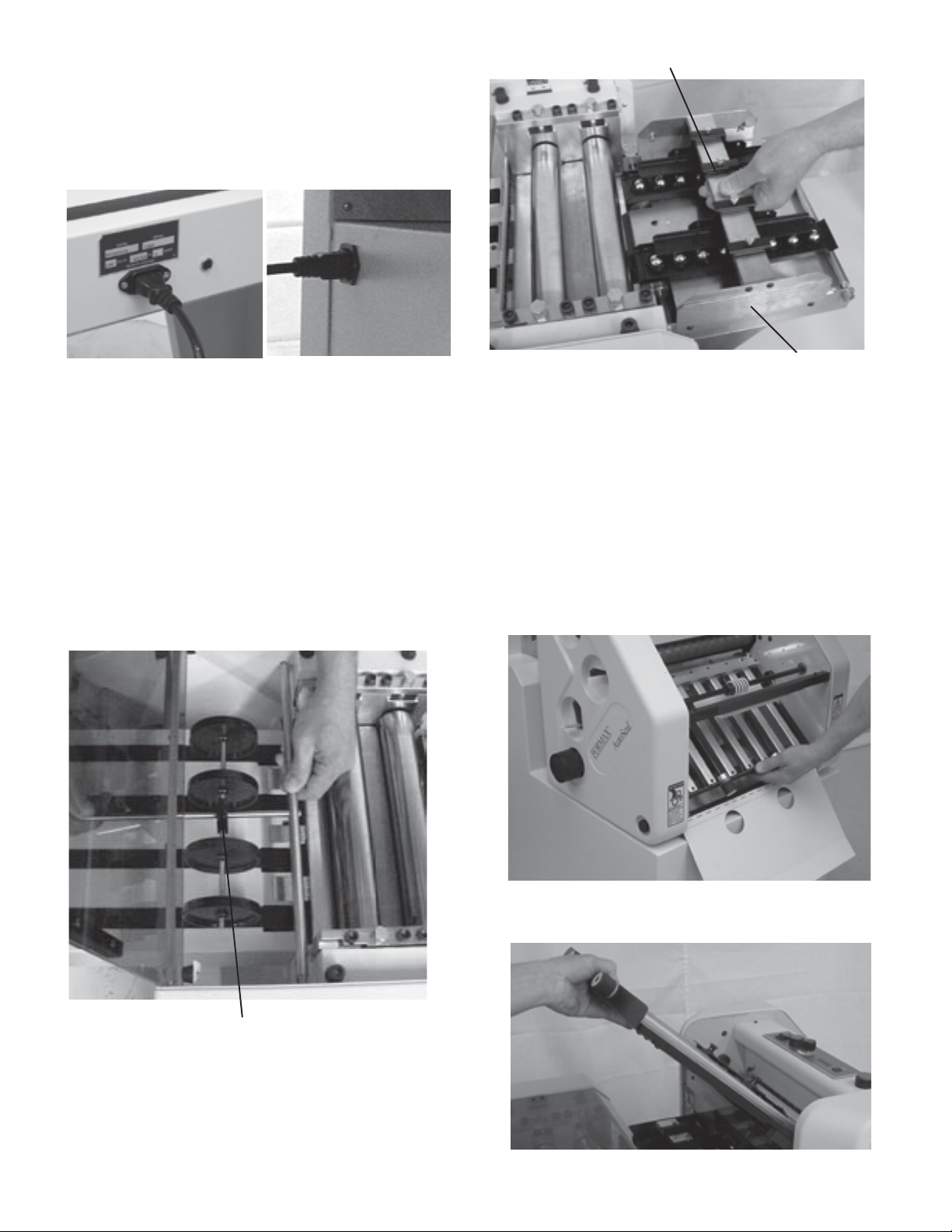
7. Plug one end of the conveyor plug into the conveyor
and the other into the sealer. The conveyor inlet is on
the non operator side of the conveyor and the sealer
inlet is located on the non-operator side of the sealer
outfeed (Fig 7a & 7b).
Eight-ball track
Fig 7bFig 7a
8. Install the conveyor nip rollers to sealer. Insert
the spring-loaded end (right side – viewed from rear
of the sealer) of the shaft into the locator hole in the
side frame, compress the spring against the side
frame and swing the opposite end into position in the
other side frame (Fig. 8).
The nip wheels can be adjusted in or out to
accommodate different size forms. This is done by
grasping (Fig. 8) the black slide handle attached to
the shaft and sliding it closer to the sealer or away
from the sealer.
Fig 9
Transfer deck
Steps for assembling the 2092/2082 folder:
1. Set the folder on the cabinet and line it up with the
recessed holes. Attach the folder to the cabinet from
the underside with the two screws provided.
2. Install the #2 (lower) fold plate. Lower the cover and
insert #2 fold plate making sure the pins latch into the
rail guides and tighten the eccentric plate locks. Note:
Both plates have two sets of locating holes in the plate
rails. The fi rst set is used when the plate defl ector is
down, the other when the plate is open (Fig 10).
Fig 8
Black Slide Handle
9. Place the eight ball track onto the folder/sealer
transfer deck. Line the notches in the track up with
the studs on the deck and set the deck into place
(Fig. 9).
Fig 10
3. Install the #1 (upper) fold plate (Fig 11).
Fig 11
4
Page 7
4. Make sure the fold plate pins are located in the
guide rails, then lower the plate locks. Place the sound
cover on top of the #1 fold plate (Fig. 12).
Fig 12
5. Install the feed table
(follow these steps for
the 2092 for the 2082 skip to steps 5a through
5b on page 5 for transfer table install and burster
attachment)
. Insert the table between the folder side
frames. Install the feed table so the holes in the side
brackets mate with the mounting holes inside the
folder side frames (Fig 13a). Insert mounting pins
(Fig 13b).
NOTE: Mounting pins should be located in the
UPPER SET of threaded holes.
Locating mounting holes
6. Connect the compressor hoses to the feed
table assembly. The sucker wheel hose threads
through the plastic hose clamp and table support,
underneath the feed table, then onto the end of the
sucker wheel tube (Fig. 15).
Fig 14
7. Attach the air hoses from the ends of the pile
guides to the double hose fi ttings of the blower. The
single hose from the sucker wheel fi tting attaches to
the vacuum fi tting (Fig 15a & Fig 15b).
NOTE Make sure all shipping plugs are removed
from the pump openings before attaching the hoses.
Plastic Hose Clamp
1
Fig 13a
Fig 15a
1
Fig15b
3
2
3
Blower hoses
Vacuum Fitting
2
Fig 13b
5
Page 8
5a. Install the transfer table for the 2082. Insert the
table between the folder side frames and set the
notches on to the mounting pins (Fig 16).
Locating mounting pins
Fig 16
5b. Align the outfeed of the burster with the transfer
table and push the burster forward until the mounting
holes of the transfer table and the burster line up.
Slide mounting pins into holes to lock the table in
place (Fig 17).
Fig 17
Locating mounting pins
6
Page 9

CONTROL PANELS
Conveyor control panel
No. NAME FUNCTION
1 Power Switch Press to turn the conveyor on (I) and off (O)
2 Runout Press to gather forms
3 Speed Control Knob Select the speed to run the conveyor
Folder control panel: located on top of the roller guard cover
1
Fig 18
1
Fig 17
2
2
3
3
4
5
6
No. NAME FUNCTION
1 Roller Stop Button Press to stop the rollers.
2 Counter Reset Button Resets the counter
3 Counter Counts number of forms processed
4 Speed Control Knob Select the speed to run the folder
5 Roller Start Button Press to start the rollers
6 Compressor On/Off Press to turn the compressor on (I) and off (O)
Burster control panel
(2082)
3
1
Fig 19
No. NAME FUNCTION
1 Counter Counts number of forms processed
2 Counter Reset Key Resets the counter
3 Stop Button Press to stop the burster at infeed or outfeed
4 Speed Control Dial Select the speed to run the burster
5 Start Button Press to start the burster at infeed and outfeed
6 Interlock Indicates cover upen, jam grill in up position, folder not running
7 Jog Switch Advances forms forward or backward at infeed and outfeed
8 Form Length Sets the length of the form to be bursted
9 Power Turns burster on and off
2
4
75
6
8
7
9
Page 10

2092 POWER & INTERLOCK HOOKUP
Folder
Fig 18a
Sealer
7
6
4
5
2
Fig 18b
3
1
No. NAME FUNCTION
1 & 2 Interlock Shuts down the sealer from the folder
3 Interlock Shuts down the folder from the sealer
4 Compressor Power Cord Connects power from compressor to folder
5 Folder Power Cord Connects power from folder to sealer
6 Folder Power Switch Press to turn folder on (I) or off (O)
7 Main Power Cord Supplies power to folder
8
Page 11

2082 POWER & INTERLOCK HOOKUP
Burster
Sealer
4
Folder
1
3
2
5
6
7
8
No. NAME FUNCTION
1 Interlock Shuts down the burster from the folder
2 Burster Power Cord Connects power from burster to sealer
3 Folder Power Cord Connects power from folder to sealer
4 Main Power Cord Supplies power from wall to machine
5 Bypass plug Bypasses
6 Interlock Shuts down the sealer from folder
7 Interlock Shuts down the folder from sealer
8 Folder Power Switch Press to supply power to folder
9
Page 12

OPERATION
2092 Operation
Squaring
In order for your machine to fold squarely, it must be fed
into the rollers square. Your 2092 has been adjusted
at the factory and should only require periodic checks.
The 2092 has a unique feed table adjustment feature to
quickly and easily adjust it if needed.
Fig 20
1. Adjust the feed table squaring screw and align the
center line of the scale with the center mark on the
feeder table (Fig 20).
Front Guide Adjusting Knob
3. Raise the sheet separator counter clockwise (ccw)
so it is away from the sucker wheel (fig. 22). Place
a sheet of the paper to be folded on the feed table.
Slide the sheet forward into the rollers. The sheet
must contact the rollers evenly and not touch the side
guides. Turn the hand wheel so about 1/2” (3mm) is
pulled into the rollers.
4. Position the operator side guide so it is just
touching the sheet but not pushing it. The side guide
must be even to the sheet from end to end. Tighten
the front lock knobs then the rear knobs, (fig 20 &
21).
5. Repeat step 4 on the non operator side guide.
6. The paper will now feed square into the rollers.
Now that the side guides are square, the feed table
squaring screw, (Fig. 20), can be adjusted for fine
tuning the overall squareness.
Vacuum Feed Sheet Separator
The sheet separator will have to be adjusted for the
weight of paper you are folding. Ideal adjustment
will feed only one sheet without marking the paper or
feeding doubles. Use the following procedure to get
started.
Fine tune these adjustments according to the
condition of the paper and the environmental
conditions of your particular work area.
Adjustment Procedure
Raise the separator (ccw) to avoid marking the
sucker wheel.
NOTE: DO NOT MAKE SEPARATOR
ADJUSTMENTS WHILE THE FOLDER IS
RUNNING.
Fig 21
Scale
Side Guides
2. Loosely position the feed table side guides to the
scales on the feed table, (fig 20 & 21). Read the front
scale at the inside edge of the side guide clamp block.
The rear scale will line up with the inside edge of the
side guide. The scales are set up to center the paper
on the sucker wheel. Initially set each guide 1/4” (6mm)
wide. Do not tighten the lock knobs.
1. Raise the separator (ccw) to avoid marking the
sucker wheel.
Fig 22
Separator Guide
Adjusting Knob
Separator Guide
Plate
10
Page 13

2. Turn the hand wheel until the separator tip is
positioned over a solid portion of the sucker wheel,
i.e. between the rows of holes.
3. Place a one inch wide (25mm), double thickness
piece of paper to be folded under the tip of the
separator plate. Lower the separator clockwise (cw)
until there is a slight drag on the paper as it is pulled
from the separator.
Fig 23
4. The vacuum advance knob is located on the side
of the feed table (Fig. 23). Adjusting the knob will
position where the vacuum contacts the stock of
paper. Raising the knob will move the vacuum away
from the lift and toward the rollers (light papers).
Lowering the knob will move the vacuum contact
toward the lift and away from the rollers (heavy
papers).
Horizontal Separator Adjustment
1. Raise the separator (ccw) to avoid marking the
sucker wheel.
2. Loosen knob (ill. 2).
3. As a starting reference, turn the hand wheel until
a set of sucker wheel holes is at the 12 o’clock
position.
Feeding Paper
NOTE: Set folds with standard copy paper so that
the folds line up with the perfs on the pressure seal
forms.
1. Load a stack of paper onto the feed table. The
stack should be no higher than the side guides , 2”
(51mm). Position the backstop up against the lift.
2. Turn on the air/vacuum pump. The air should float
the bottom of the lift approximately 1/16 to 1/8” (16 to
32mm). Air blast can be controlled by adjusting the
valve located at the end of each side guide (Fig. 24).
4. Adjust separator assembly so that the plate is 1/16”
forward of the 12 o’clock position, measure from the
feed side of the plate.
5. Tighten knob (ill. 2).
Fig 24
11
Page 14

Separator Guide Lock
Set Screw
Air Blast
Openings
Fig 25
3. Turn the speed control to ½ or full speed. Place
your thumb on the back of the stack to keep paper
from feeding. Press the green button, the sucker
wheel will start to turn. Reduce the pressure of your
thumb to feed only 3 to 4 sheets. Press your thumb
down to stop the feeding again. Press the red button
to stop the sucker from turning. If the paper did not
feed, adjust the position of the vacuum advance,
bleeder valve, or sheet separator.
There is a bleeder valve on the vacuum pump,
(Fig 26), which allows for vacuum adjustment from
completely off to completely on. General settings for
the bleeder valve are half open for 20# stock, and
closed for 80# and heavier stock. If your machine
is feeding doubles, this can be opened slightly to
“relieve” some of the vacuum and stop the double
feeding.
4. Check the accuracy of the 3 or 4 sheets fed. It
may be necessary to adjust the fold stop, or the
squareness of the fold stop, or the squareness of
the side guides. Try only one adjustment at a time
then repeat step 3
5. If the folds look good, the job may now be run.
The speed of the folder will affect the accuracy of the
folds. Folds set up at slow speed will be difficult at
high speed and will need to be fine tuned.
NOTE: All of the controls mentioned above contribute
to smooth and accurate folding. There are many
combinations possible depending on the condition of
the paper and environment.
Bleeder Valve (Vacuum Adjustment)
Fig 26
12
Page 15

2082 Operation
Slitter Adjustment
Edge Slitters
8-Pin Tractor, OP 8-Pin Tractor, DrCenter Paper Guide
Wedger
Screw
4. Center leading edge of form at infeed end of the
burster.
Alignment Mark
5. Position tractors to proper form width by releasing
thumbscrews on top of tractors and sliding tractors to
proper width. Raise tractor gates.
6. Lay margin holes of form over feed pins. (Fig. 29)
Fig 27
Form Set-up Procedure
1. Turn on the machine. Measure form length.
2. Press the form length switch on the burster to
align the alignment mark with the form length on form
length scale. (Fig. 28)
Form Length Scale
Fig 28
Alignment Mark
NOTE: Do not stretch form too tightly between
pins; pins should be centered in margin holes.
Fig 29
7. Close tractor gates and lock tractors by tightening
thumbscrews.
8. If using edge slitters, position alignment mark
where you wish to slit. (Fig. 27)
9. If slitting, be sure that slitter blades are engaged.
This is accomplished by rotating wedger in a
counterclockwise direction as far as they will go
without force. (Fig. 27)
10. Lock edge slitters in place by tightening
thumbscrews clockwise. (Fig. 27)
NOTE: If you do not want to slit, push edge slitters
away from form and tighten thumbscrews.
3. Place form stack on pull down tray on front of the
burster.
11. By pressing jog switch in forward position,
advance form through feed rollers until snap rollers
grab the form.
13
Page 16

12. If necessary, adjust form length so that form
starts to burst when perforation is just under tear
points.
NOTE: Tear points can be moved to allow operator
to position them at any location along tear bar. Tear
points should be set between perforations that run
vertically the length of the form. (Fig. 30)
13. The tear bar is adjustable to accommodate
characteristics of various forms. To adjust height
bar must be pushed to compress spring and lift out.
Rotate 180 degrees (turned over) and replaced
making sure that square end of bar locks into
brackets. (Fig. 31, shown in HIGH position)
Fig 31
Fig 30
14
Page 17

Form Set -Up Procedures With Optional
Imprinter
10. Move timing collar so that mark on collar aligns
with mark on side frame. Tighten setscrews.
NOTE: It is recommended that numbered forms or
checks fed into imprinter should be last form first,
right side up.
1. Center leading edge of form at infeed end of
machine so that outer edges of form extend equally
beyond guide straps on each side. If you find that
edges come within about 1/4” of guide straps, offset
form in either direction to avoid this condition.
2. If form length is 3 1/2”, 7”, 10 1/2” or 14”, rollers
must be timed. Time rollers by activating jog switch
until timing marks on the rollers are vertical and in
view in cutouts in feed and snap roller covers.
3. Position tractors by releasing and sliding to proper
form width. Raise tractor gates. Place forms on feed
pins as shown in. Close tractor gates and secure in
position.
4. Loosen thumbscrew on ink roller unit and slide unit
away from signature area on form.
5. Loosen setscrews on plate cylinder. If setscrews
are not in view, rotate free wheeling cylinder until
they are in view.) Horizontally align plate cylinder with
signature area on form. Tighten setscrews.
6. Loosen setscrews on imprint cylinder. (If setscrews
are not in view, use jog switch to bring them into
view.)
11. Remove forms from tractors. Install signature
patches on imprint cylinder.
12. Move ink roller directly over signature patch on
imprint cylinder. Jog forward, if necessary, so that
imprint cylinder turns to a point where signature patch
should touch ink roller. Adjust ink roll thumbscrews so
ink roll turns when signature patch makes contact.
For darker impression, turn adjustment thumbscrews
clockwise.
NOTE: The signature saddle has been factory
adjusted to fit a .092 thick signature patch. If
adjustment is required to lower or raise the height
of signature saddle for a different signature patch
thickness, release imprinter side plates from their
locked positions. Pull back latch finger to release
plates. Loosen side setscrews to free top setscrew
Turn top setscrew in at half-turn increments until
required height is reached. Tighten side setscrews
and slide imprinter module back into position.
Normal Loading
NOTE: Imprinter must be timed each time you load a
different form into Burster for imprinting.
1. Jog machine forward until timing collar mark is
aligned with side panel mark.
2. Place forms to leading edge to timing mark.
7. With no signature saddles on imprint cylinder,
move forms forward so signature area is centered
over plate cylinder shaft.
8. Center signature cylinder over signature area
(NOTE: Setscrews should be facing you.) and center
signature plate locator pins directly over imprint area
on form. Tighten setscrews.
9. Advance forms forward so that next horizontal
perforation aligns at top edge of plastic tractor or
alignment mark on metal tractor.
3. Advance (jog) forms forward through imprint area.
Stop leading edge of form in front of slitters.
4. Move slitters to trim proper amount of trim
and engage slitter blades by turning wedgers
counterclockwise. Lock down slitters.
5. Advance forms through slitters and check for
proper slitting. Advance on through to Tear Bar.
15
Page 18

6. Set up tear bar as before. (Fig. 33)
7. Close Safety covers. Machine is now ready to
burst and imprint. Press the Start Button and adjust
machine speed to speed desired.
Burster Operating Hints
1. To stop the machine just push on either one of
two stop buttons. Opening safety cover or lifting jam
detection grill will also stop machine.
2. To restart machine start button must be pressed.
CAUTION: Machine will restart at same speed that it
was running at unless speed control thumbwheel is
turned down.
3. Some paper has a natural curve. Sometimes this
curve tends to catch air and sail. If this occurs, try
running them upside down.
4. Perforations vary in strength. If forms are bursting
hard, tearing, or breaking behind tear bar, vary form
length setting up to 1/2”ahead or behind actual form
size setting, and/or put tear bar in low position.
Fold Plates
(2092 & 2082)
Plate set up will depend on the type of stock and type
of fold you require. The fold plate design on the folder
allows changing from open or closed deflector (up
and/or down folds) without removing or turning the
plates.
A good understanding of the roller/plate
configuration will help you decide which plate to
open or close for up or down folds. Illustration 3
shows the paper path for a common “Z”-fold.
A self-adhesive folding guide label has been
conveniently placed on the conveyor extension tray.
Used along with scales on the fold plates, the guide
will help you quickly establish a rough set up for
some of the most common folding jobs.
Plate Stop
Inch/mm
Scale
Fig 32
Quick Setup Scales (read at
these points)
16
Page 19

Coarse adjustments are made by loosening the lock
screws on the plate stops, then moving the stop (Fig.
26). The plate stop lines up with the scale marks
along its front edge (not where the paper contacts
the stop). Fine adjustments are made with the micro
adjust knobs on the ends of the fold plates (Fig 27).
Fig 33
Roller Caliper Set Up
To provide the proper clearance between rollers,
¾” wide paper strips are inserted into the calipers.
Simply press the caliper lever and insert the correct
number of strips into the open gap. Put the same
number of strips into both sides of the folder. Do not
use folded or torn strips of paper (they may give false
readings).
Adjustable calipers are used on the folder to obtain
clean crisp folds on a variety of stock (Fig 28). The
proper amount of paper strips (of the same material
being folded) in each caliper on both sides of the
folder will give the best grip for a good fold. As the
paper is folded, the thickness of the paper passing
between the rollers increases. The number of paper
strips placed in the calipers should be equal to the
minimum thickness of the paper passing between the
rollers (tail end of the sheet).
Roller Calipers
Illustration 4 diagrams the position of rollers, fold
plates, feed table, calipers and the correct number
of paper strips to be placed into the calipers for a
common “Z” fold.
Roller Caliper Quick Set Up Guide
The chart below gives the set ups for calipers for several
common folds.
Fold Type # 1 Caliper # 2 Caliper # 3 Caliper
Letter “C” 1 1 3
“Z” 1 1 3
Half 1 2 2
Double Parallel 1 2 4
Uneven “Z” 1 1 3
Uneven “C” 1 1 3
Fig 34
17
Page 20

Safety Covers
Fault Detectors
The burster (2082), folder and sealer are equipped
with plexi safety covers (Fig. 35a, 35b & 35c).
The 2092 and 2082 will not run unless plexi-safety
covers are in the lowered position.
Burster Safety Cover
Fig 35a
Folder Safety Cover
Burster (2082) - The burster is equipped with on
outfeed jam detector grill. This device senses jams
between the burster and the transfer table and stops
the burstor until the jam is removed and the machine
is restarted (Fig 36).
Burster Jam Grill
Fig 36
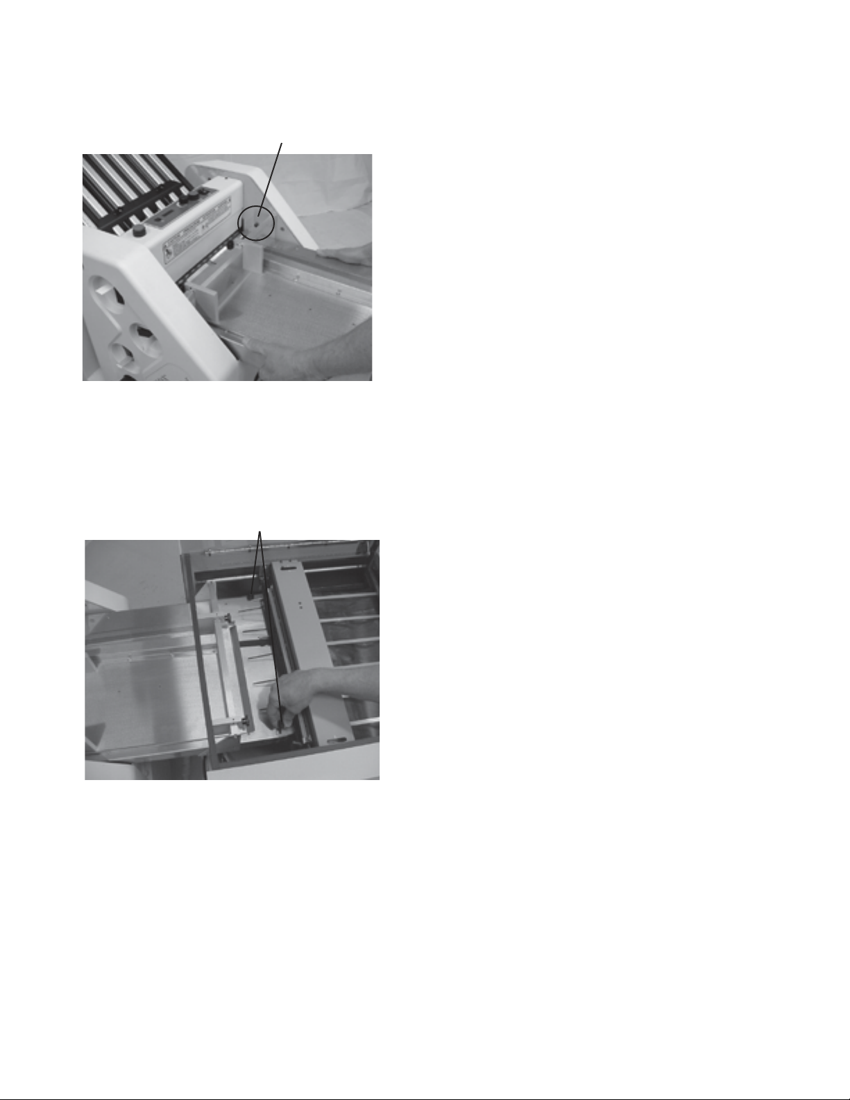
Folder - The folder is equipped with a delivery area
jam detector. This device senses jams at the eight
ball transfer deck and immediately stops the burster,
folder, and sealer until the jam is removed and the
machine is restarted. The jam detector is mounted
on the center of the tie bar and looks similar to a third
stacker spring, it may be reformed for best operation
(Fig. 37).
Fig 35b
Fig 35c
Sealer Safety Cover
Sealer - A photo-eye sensor is located on the Eight
ball transfer deck before entering the sealer unit.
This device senses jams and immediately stops
the sealer, burstor (2082) and folder until the jam is
removed and the machine is restarted (Fig. 37).
Folder Jam Detector
Sealer Photo-eye
18
Page 21

DAILY MAINTENANCE
General Cleaning
Take a few minutes at the end of each day to wipe off accumulations of paper dust. Cover your machine when
not in use. These practices will keep your machine clean and in tip-top operating condition.
Fold Roller Cleaning
Keep fold rollers clean. Most folding problems are the result of material accumulations on the fold rollers.
Although designed to minimize accumulations, over a period of time, ink and dust buildup will prevent the
rollers from gripping the stock evenly. Rollers must be cleaned on a regular basis to maintain optimum folding
performance.
Disconnect the power, remove the fold plates and clean rollers with Formax approved cleaner designed for the
type of rollers your machine is equipped with. Turn the rollers with the hand wheel never attempt to clean rollers
with the machine running.
Check rollers periodically for wear. During normal use fold rollers will gradually wear. Worn rollers will be evident
by increased setup times, increased spoilage, inaccurate folding and inability to control the sheet. If one or more
of these conditions are noted, contact your authorized Formax folder dealer to inquire about inspection and/or
possible roller replacement.
Sealer Roller Cleaning
Keep sealer rollers clean. Sealing problems may occur if printer toner builds up on the steel rollers.
Disconnect the power, lift the sealer safety cover and wipe the rollers down with Formax approved lint free cloth
and roller cleaner.
19
Page 22

TROUBLESHOOTING
TROUBLE POSSIBLE CAUSE REMEDY
Machine not running Is the power on?
Make sure the power to the folder, sealer
and conveyor are in the on position.
Check to make sure the wall outlet has
power
Is the machine plugged in?
Are the safety covers lowered?
No power even with machine
turned on, plugged in and wall
power is on?
Double feeding forms Is the feeder set properly?
Is paper stuck together?
Using paper other than
specified?
Sealer jams Double feeding? Turn power off, insert jam clearing bar
Folder Jams Double feeding?
Paper stuck in fold plate?
Metal rollers dirty Toner is on metal rollers of
sealer?
Paper fold gets out of
place
Paper stops have moved?
Make sure all the plugs are plugged in
properly
Make sure the safety covers for the
folder and sealer are lowered.
Call Service
See pages 7,8 & 9.
Separate paper from each other.
Paper other than specified may cause
mechanical trouble.
into sealer roller and turn back counter
clockwise until jam is cleared.
Turn power off, turn hand wheel counter
clockwise and clear jam.
Turn power off, remove fold plate and
clear paper.
Unplug machine and clean with
approved cleaner.
Rotate the fine adjustment knobs to
correct movement.
Is folding roller dirty?
Paper jam occurs often Is folding roller dirty?
Is inside of machine dirty?
Are conveyor nip rollers in
proper positions?
Is paper curled?
If paper jamming continues.
Clean with approved cleaner.
Clean with approved cleaner.
Clean inside of machine.
Set rollers to proper position.
Let paper sit curl side down with weight
on top to eliminate curl.
Call for service.
20
Page 23

Forms Creasing Form is not exiting the folder
straight?
Check to make sure the forms are being
fed squarely.
Check to make sure the eight ball track
is sitting properly.
Check to see if the fold rollers are clean.
Documents are wrinkled
or crunched
Forms in burster creep to
one side.
Burster stalls or tears
forms
Form is not entering the sealer
straight?
Creasing continues
Fold plates are not inserted
correctly?
Piece of paper or other material
is stuck in the fold plate?
Infeed guides not set properly.
Roller tension not uniform
across roller.
Tear bar in high position.
Burster not running fast
enough.
Incorrect form length setting.
Tear points not adjusted
properly across face of form.
Tough form perforations.
Check to make sure the eight ball track
is sitting properly.
Call service.
Remove and reinstall fold plates. Be
sure they’re properly positioned.
Remove object from the fold plate.
Reset Guides
Check and adjust roller tension, Call
Service
Put bar in low position pg. 14
Increase burster speed
Reset paper length pg. 13
Adjust tear points pg. 14
Adjust tear points pg. 14
Burster rollers don’t
rotate / machine runs.
Won’t burst properly.
Poor slitting. Slitter blades not making
Slipped belt, Broken drive belt,
Loose pulley.
Incorrect roller tension.
Carriage not properly
positioned.
Tear point not set correctly.
Tear bar not set correctly.
contact with one another.
Worn blades.
21
Call Service
Check and adjust roller tension, Call
Service
Reset carriage position
Adjust tear points pg. 14
Adjust tear bar position pg. 14
Adjust slitter blade position
Replace blade, Call service
Page 24

Forms pull out of burster
tractors.
Roller timing off.
Incorrect form length setting.
Call service.
Reset form length pg. 13
Large variations in trim
accuracy
Snap roller carriage will
NOT move
Loop forming between
the slitter and the infeed
roller.
Incorrect feed roller tension.
Tractor drive pulley bound up.
Tractors binding internally.
Tractor pins not centered in
margin holes.
Dull slitter blades.
Tractor timing is off.
Paper not centered to slitter
feed.
Margin slitter setscrew not
tightened down.
Defective switch or motor.
Broken carriage drive chain.
Loose setscrew on carriage
advance shaft or on motor.
Obstruction on rack.
Obstruction at the pivot arm.
Obstruction between the
infeed and snap rollers.
Broken flow strap.
Check and adjust roller tension, Call
Service
Check for paper jam and clear, Call
service.
Call service.
Adjust tractors pg. 13
Replace blade, Call service
Call service.
Realign paper
Tighten setscrew
Call Service
Call Service
Tighten setscrew, Call service
Remove obstruction
Remove obstruction
Remove obstruction
Call Service
Bent infeed finger.
Tear bar in low position.
Too many tear points.
Need Anti-tenting bracket.
22
Call Service
Put bar in high position pg. 14
Adjust tear points pg. 14
Call Service
Page 25

Leading Edge
Make copies of this page on copy paper for fine tuning folds
Instruction For Lining Up Folds
1. Place a stack of these sheets into the feeder and fold
one (1) or two (2) sheets.
2. Take a folded sheet from the catch tray and lay it on
top of a pressure seal form lining the leading edge of
this sheet up with leading edge of the pressure seal
form.
3.
If the folds on this test sheet do not line up with the
perforated folds on the form, the fold plates need to
be adjusted up or down to make the folds line up.
Refer to Fig. 1 for a “Z” fold and Fig. 2 for a “C” fold.
-
If fold “A” on the test form is right of the perforation on
the pressure seal form move the top fold plate
stop up. If fold ”A” is below move the top fold plate
stop fold stop down.
-
If fold “B” on the test form is right of the perforation
on the pressure seal form move the bottom fold plate
stop down. If fold ”B” is to the left move the bottom
fold plate stop up.
Fold “A” Fold “B”
Fig. 1 “Z” fold Form
Fold “A” Fold “B” Leading Edge
Leading Edge
23
Fig. 2 “C” Fold Form
 Loading...