

Page 1

FD 2052IL AutoSeal® System
12/2007
OPERATOR MANUAL
FIRST EDITION
Page 2

Page 3
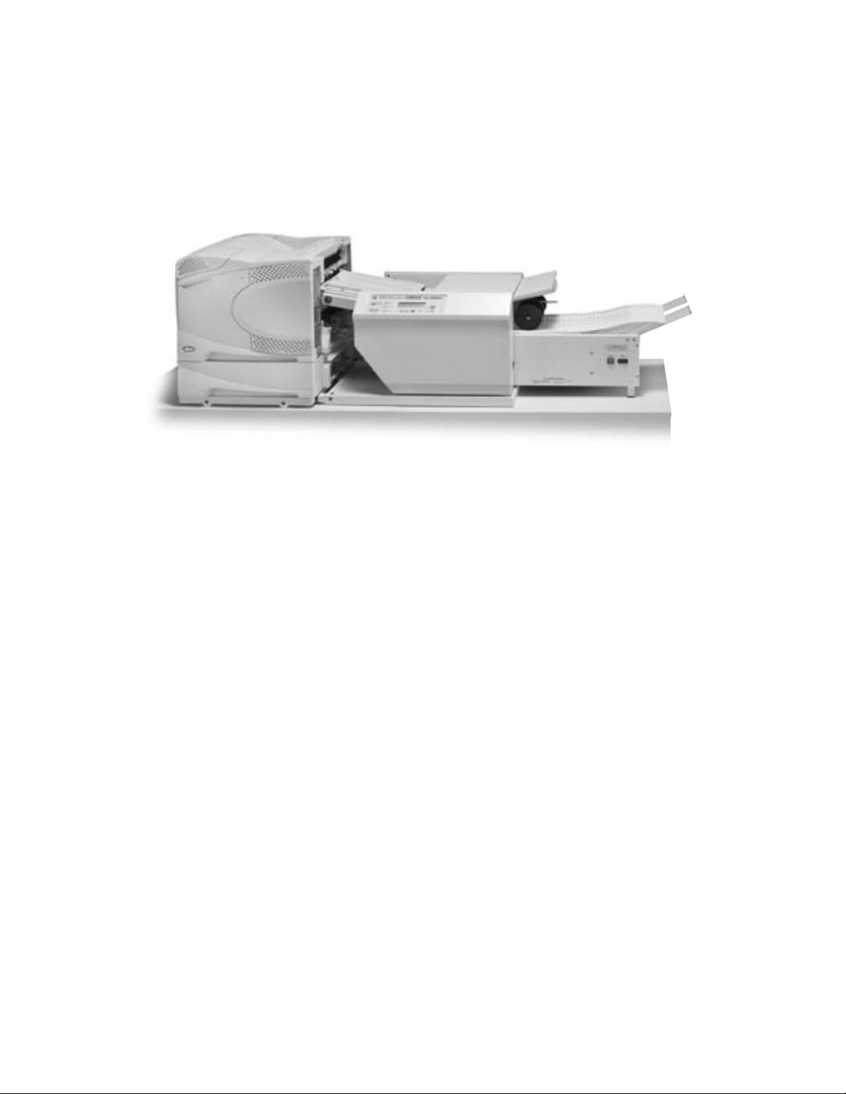
TABLE OF CONTENTS
DESCRIPTION 1
SPECIFICATIONS 1
UNPACKING 1
SETUP 2
Alignment Base Setup 2
Sealer Setup 2-3
Printer Setup 4
Alignment Stoppers 5
CONTROL PANEL 6
OPERATION 7-8
Offline Print Test 8
Normal Operating Conditions 8
Setting Custom Folds 9
TROUBLESHOOTING 10-12
TEST SHEET 13
OPTIONAL CONVEYOR INSTALLATION 14
Page 4

Page 5
DESCRIPTION
FUNCTION
With the Formax FD 2052IL AutoSeal System operators can print, fold and seal all in one streamlined process.
One-piece pressure sensitive forms are loaded into an existing laser printer where they’re printed and fed directly
into the IL Pressure Sealer where they’re folded, sealed and output as a mail-ready piece.
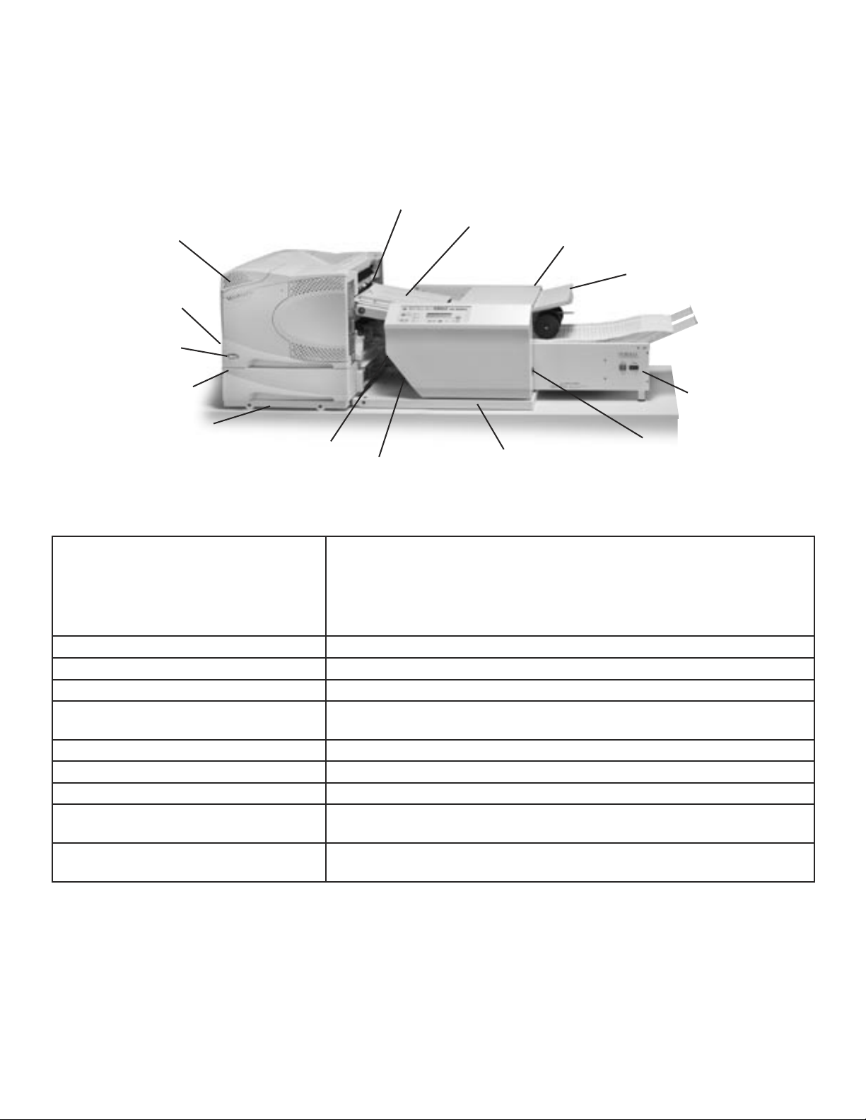
FD 2052IL System
Printer (not included in IL System)
Upper printer feed tray
Printer power switch
Lower printer feed tray
Printer alignment base
Paper length toggle switch
Printer outfeed / sealer infeed
Lower fold plate
Sealer transport deck
IL Pressure Sealer
Sealer alignment base
SPECIFICATIONS
Printer Compatibility: HP & Troy 4200, only with two 500-sheet trays
HP & Troy 4250, only with two 500-sheet trays
HP & Troy 4350, only with two 500-sheet trays
Consult your Formax dealer for an updated list of additional
FD 2052IL compatible laser printers.
Upper fold plate
Optional 18” conveyor
Sealer power switch
Speed: Printer dependent
Paper Size: Up to 8.5” x 14”
Duty Cycle: Up to 175,000 pieces per month
Power Requirements: FD Model: 120 Volts AC, 50/60 Hz
FE Model: 220 Volts AC, 50/60 Hz
Dimensions (closed) **: 17” W x 43.5” L x 16” H
Dimensions w/18” Conveyor (closed): 17” W x 58.5” L x 16” H
Tabletop Area Required: 19” W x 49” L
Tabletop Area Required
w/18” Conveyor:
Dimensions with Cabinets and
18” Conveyor:
** Dimensions include IL Pressure Sealer and IL Alignment Base.
19” W x 64” L
17” W x 69” L x 45.5” H
UNPACKING
1. Check package for shipping damage. If there is shipping damage do not discard the box.
2. CAUTION: Two people must lift the Pressure Sealer out of the box.
3. Package should contain the IL Pressure Sealer and two piece IL Alignment Base.
1
Page 6
SETUP
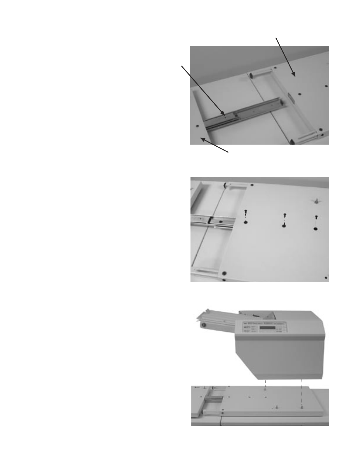
Alignment Base Setup
Connecting slider
1. Place two parts of alignment base face up.
(Fig. 1).
Alignment Base, Pressure Sealer Section
2. Extend connecting slider and slide into slot on
sealer section of base, lining up the screw holes
wih the holes in the top of the base (Fig. 2). Insert
the leading two screws first, do not tighten down at
this point. Align third screw hole in the slider with
the top cover and insert screw. Tighten all three
screws into place.
Sealer Setup
1. Align the 2052IL with the pins located on the
alignment base and lower into position. (Fig. 3)
Caution: Two people should lift and lower the
2052IL.
Fig. 1
Alignment Base, Printer Section
Fig. 2
Fig. 3
2
Page 7

2. Install lower fold plate into pressure sealer.
Match up alignment pins (Fig. 4a) on the pressure
sealer with grooves on the underside of the fold
plate.
Lower fold plate
alignment pins
3. Plug the cord into the fold plate receptacle (Fig.
4b).
4. Install upper fold plate into pressure sealer.
Match up alignment pins (Fig. 5a) on the pressure
sealer with grooves on the underside of the fold
plate.
Fig. 4a
Fig. 4b
Lower fold plate
power connector
Upper fold plate
alignment pins
5. Plug the cord into the fold plate receptacle (Fig.
5b).
CAUTION:
Do not operate the machine without the
fold plates installed and plugged in.
Fig. 5a
Fig. 5b
3
Page 8

Printer Setup
1. Remove back door from the printer. Lower door,
depress the side tabs to release and pull the door
out (Fig. 6).
2. Place printer on alignment base. First align
bottom feed tray with the pins on the printer
alignment base and lower into position. Then align
printer with the bottom feed tray pins and lower into
place. (Fig. 7)
Fig. 6
Side tabs
3. Secure the printer to the bottom feed tray with
the locking mechanism located on the backside of
the printer. (Fig. 8)
Fig. 7
Fig. 8
Locking mechanism
4
Page 9

Alignment Stoppers
The alignment base stoppers are used to keep
the printer from making contact with the sealer
infeed. The exit rollers of the printer and the sealer
infeed throat should not come into contact during
operation. There should be a gap of approximately
1/8” between the rollers and the sealer Infeed
throat.
1. Slide the printer up to the sealer infeed throat so
that there is approximately a 1/8" gap between the
printer out feed and the sealer infeed throat. Using
a 1/8” standard allen wrench, loosen the locking pin
of each alignment base stopper. (Fig. 9)
2. Pull the stopper out from the pressure seal
alignment base until it meets the edge of the
printer alignment base, be sure to maintain the gap
between the printer outfeed and the sealer infeed.
(Fig. 10a & 10b)
Fig. 9
Fig. 10a
Alignment base stopper
Locking pins
3. Using the allen wrench, tighten both locking pins
to hold the stopper into place. Now it’s possible to
slide the printer away from the 2052IL infeed throat
and back into place without having to reset the
position. (Fig. 11)
Repeat with the second stopper.
Fig. 10b
Fig. 11
5
Page 10

CONTROL PANEL
2
1
9
8
7
3
4
5
6
1 Standard Fold Menu Press to select standard fold type
2 Fold LED’s Indicates fold type selected
3 Display Screen Displays all current functions
4 Fold Setup Press to automatically set the fold plates
5 Counter Reset Resets counter and resets faults
6 Service Mode Used to perform service diagnostics
7 Custom Fold Selection Push to select custom folds
8 Adjust Tables “-” “+” Adjusts fold plate measurements for programming custom folds
9 Table A / Table B
Toggles between top and bottom fold plate when setting custom
folds
Standard Folds Menu:
The Standard Folds Menu consists of three folds; Letter (C-fold), Zig-Zag (Z-fold), and Single (Half fold). By
pressing the green button in the Standard Folds Menu, you can toggle between the fold settings. An indicator
will light up on the fold type selected. These fold types are standard for 11” and 14” forms.
Set the form length by flipping the 11”/14” toggle switch located on the left of the pressure sealer (fig. )
Custom Folds Menu:
To use a custom fold setting press one of the custom fold buttons (1, 2, 3-9). Press the 3-9 button multiple
times to toggle through the 3rd and the 9th custom folds.
6
Page 11

OPERATION
1. Plug in cord and turn power on for both the
pressure sealer and the laser printer.
2. Set the form length by flipping the 11”/14”
toggle switch located below the feed deck on the
operator side (Fig. 12)
3. Select the fold type from the “Standard Fold
Menu” (Fig.13). If a custom fold is being used
select fold from the Custom fold Menu (see pg 9
to set a custom fold.)
4. Press the “Fold Setup” button to automatically
set the fold plates (Fig. 14).
Fig. 12
Standard Fold
Selection Button
Fig. 13
Form Length Switch
5. Place pressure seal forms in printer paper tray.
Paper should be loaded into the approved HP
printers face down with the glue edge trailing.
Locate the paper orientation guide on the printer
and load accordingly (Fig. 15). The print side
glue edge is considered the top of the document.
Once forms are loaded perform an offline print
test (see pg. 8) to make sure the printer and
sealer are aligned properly. If the print test is
satisfactory begin online operation.
Fig. 14
Fig. 15
Fold Setup Button
Printer Paper
Orientation Guide
7
Page 12

OffLine Print Test
In order to test the system offline follow the directions below to ensure proper alignment and fold setup. For
further printer test mode operation information or if the printer being used is not listed below refer to the printer
operator guide. Note: The sealer is activated when the form passes over the photo-eye located at the mouth of
the sealer transport deck.
Test Mode HP 4350
1. Power up the Printer and Sealer
2. Load forms into printer face down with glue trailing.
3. When “Ready” appears in the printer window press the button.
4. Press the button to highlight “Information” and press the button.
5. Press the button again to print “Menu Map.” Five pages will be printed.
6. To print additional pages repeat steps.
Test Mode HP 4200 / 4250
1. Power up the Printer and Sealer
2. Load forms into printer face down with glue trailing.
3. When “Ready” appears in the printer window press the button.
4. “Information” will be highlighted, press the button.
5. Press the button again to print “Menu Map.” Five pages will be printed.
6. To print additional pages repeat steps.
Normal Operating Conditions
1. Steam may be present when the form comes out of the printer and enters the sealer transport deck. This is
a normal operating condition if the transport deck is cool when operation begins. The steam should go away
after 5 - 10 forms run through the system allowing the transport deck to warm up.
2. Moisture present on the transport deck. When forms are printed moisture is released from the forms. Due
to the enclosed IL system setup the moisture is present on the transport deck, it should lessen as the transport
deck warms up. Environmental conditions may affect the amount of moisture present as well.
8
Page 13

SETTING CUSTOM FOLDS
The Custom Folds Menu allows you to program custom folds into memory. The 2052IL can store up to nine
custom folds. To store a custom fold into memory, follow these steps:
1. Measuring Fold Lengths
Example 1: Uneven “Z”
a. Measure the length of panel “A”.
b. Measure the length of panel “B”
c. Enter these measurements according to the
instructions below.
Example 2: Uneven “C”
a. Measure the length of panel “A” + “B”
b. Measure the length of panel “B”
c. Enter these measurements according to the
instructions below.
Panel A
Panel B
Panel A
Panel B
1. Select the custom fold number you want to program.
2. Press the green button next to the Table A and Table B lights.
Note: The display will read “Tbls A: #.## B: #.## CUSTOM #”.
Table A adjusts the upper fold plate.
Table B adjusts the lower fold plate.
The “-“ and “+” buttons decrease and increase the fold numbers.
3. Press the “-” and/or “+” button to enter the length of the fold. Fine adjustments can be made with the
adjustment screw at the end of the plate.
4. Press the “Fold Setup” button and run the printer test mode to ensure the proper folds have been entered.
5. Once the folds are correct, press and hold the “Custom Fold” green arrow button until the machine sounds
a tone. The fold has been memorized.
9
Page 14

TROUBLESHOOTING
TROUBLE POSSIBLE CAUSE REMEDY
Control panel lights are
not illuminated.
No power at the wall outlet.
No power to the machine inlet.
Check wall outlet.
Check power cord for frayed/broken
wires.
Fold plate stop not
moving when “Fold
Setup” is pressed.
Sealer does not turn on
when the form enters
the throat of the sealer
transport deck.
Standard fold is
misfolding
No power to the control panel.
Internal electrical failure
Fold plate is not plugged in.
Electrical or mechanical failure
Sealer is not turned on
Sealer reset button has not
been pressed after a paper jam
Sealer breaker has popped
Photo eye is not detecting the
form
Fold plate is not plugged in.
Wrong fold is selected
Press the black breaker reset button
located on the backside of the sealer,
see pg. 12 Fig. 17.
Call for service
Plug fold plate in.
Call for service.
Check that the sealer is plugged in and
turned to the on position.
Press the “counter reset” button to reset
the sealer
Press the black breaker reset button
located on the backside of the sealer,
see pg. 12 Fig. 17.
Wipe sensor with dry cloth.
Call for service
Plug fold plate in.
Check to make sure the correct fold is
selected from the “Standard fold menu”
Fold plates are not inserted
correctly.
Piece of paper or other material
is stuck in the fold plate.
10
A custom fold may need to be created
if the fold varies from the standard fold
setting, see pg 9 for custom fold setup.
Remove and reinstall fold plates. Be
sure they’re properly positioned.
Remove object from the fold plate.
Page 15

Custom fold is misfolding Fold plate is not plugged in.
Plug fold plate in.
Wrong fold is selected
Fold plates are not inserted
correctly.
Piece of paper or other material
is stuck in the fold plate.
Fold settings are off
“Cover Open” is
displayed.
“Paper out “ is displayed. In-feed tray is empty. Place documents on the in-feed tray.
“Paper Jam” is displayed. Paper misfeed between printer
Cover open
Magnetic switch is broken.
outfeed and sealer infeed
Check to make sure the correct fold is
selected from the “Custom fold menu”
Remove and reinstall fold plates. Be
sure they’re properly positioned.
Remove object from the fold plate.
Check that the fold settings match the
actual fold lengths, see pg 9 for custom
fold setup.
Check that all covers are closed
Call for service
Slide printer back to gain access to
the printer outfeed and remove forms.
Lift top cover of printer, remove toner
cartridge and remove forms. Reinstall
toner, close printer cover, slide printer
back into position and press the “counter
reset” button on sealer to reset sealer.
Paper jammed at steel sealer
rollers.
Black marks on the folded
forms.
Fold is skewed. Printer and sealer are out of
Transport table belts do
not turn.
Documents are wrinkled
or crunched.
Fold rollers and/or steel sealer
rollers are dirty.
alignment.
Transport deck belts are dirty
Broken drive belt, worn drive
gear.
Fold plates are not inserted
correctly.
Piece of paper or other material
is stuck in the fold plate.
Remove paper and press “Counter
Reset” button, see pg 12 for clearing
instructions.
Clean the rollers with approved roller
cleaner and rejuvenator.
Check to make sure the printer and
sealer are set properly on the alignment
pins
Adjust rear pin on the printer alignment
base, see pg 12 for adjustment
procedure)
Clean belts with approved cleaner
Call for service
Remove and reinstall fold plates. Be
sure they’re properly positioned.
Remove object from the fold plate.
11
Page 16

A. Clearing paper jams from the steel pressure seal rollers:
WARNING: Turn off machine and unplug cord from its receptacle.
If a jam occurs in between the metal sealing rollers open the top cover and remove the upper fold table.
Remove the jam-clearing tool (located under the top fold table), apply the tool to the upper metal roller (Fig.
16) and turn clockwise until the paper jam is clear. (Caution: Do not apply excessive force or rollers may be
damaged.) (Caution: Do not turn counter-clockwise and force the form(s) to exit the machine or the rollers
may be damaged.) Remove the jammed form, return tool to holder and reinstall the upper fold table. Reinstall
cover and press the reset button.
Note: Press the black button (Fig. 17) near the power cord inlet to reset the breaker if necessary.
Fig. 16
Fig. 17
B. Adjusting printer alignment base pin:
The rear printer alignment base pin can be adjusted to properly align the printer with the sealer. Loosen the
rear pin using an adjustable wrench to hold the pin while using a 7/16” socket to loosen the nut. Slide the pin
forward to move the front outfeed corner of the printer forward toward the front edge of the alignment base and
slide the pin back to move the front corner of the printer back away from the edge of the alignment base. The
printer will pivot on the front alignment pin (Fig. 18).
Rear alignment pin
Back position
Forward position
Front alignment pin
Front edge
Fig. 18
12
Page 17

Leading Edge
Make copies of this page on copy paper for fine tuning folds
Instruction For Lining Up Folds
1. Place a stack of these sheets into the feeder and fold
one (1) or two (2) sheets.
2. Take a folded sheet from the catch tray and lay it on
top of a pressure seal form lining the leading edge of
this sheet up with leading edge of the pressure seal
form.
3.
If the folds on this test sheet do not line up with the
perforated folds on the form, the fold plates need to
be adjusted up or down to make the folds line up.
Refer to Fig. 1 for a “Z” fold and Fig. 2 for a “C” fold.
-
If fold “A” on the test form is right of the perforation on
the pressure seal form move the top fold plate
stop up. If fold ”A” is below move the top fold plate
stop fold stop down.
-
If fold “B” on the test form is right of the perforation
on the pressure seal form move the bottom fold plate
stop down. If fold ”B” is to the left move the bottom
fold plate stop up.
Fold “A” Fold “B”
Fig. 1 “Z” fold Form
Fold “A” Fold “B” Leading Edge
Leading Edge
13
Fig. 2 “C” Fold Form
Page 18

OPTIONAL CONVEYOR INSTALLATION
To install the 18” conveyor, follow these steps:
1. Unplug the pressure sealer from the wall outlet.
2. Remove the catch tray from machine.
3. Remove the upper fold table.
4. Plug the power cord into the underside of the conveyor.
5. Install the conveyor mounting bolts. (Fig. 19)
6. Attach the conveyor to the pressure sealer.
7. Install the stacker wheel assembly into the holes indicated below. (Fig. 20)
8. Adjust the stacker wheels to conveyor decal.
9. Plug the conveyor power cord into the power outlet on the pressure sealer.
10. Reinsert the upper fold table.
11. Plug the pressure sealer into the wall outlet.
Fig. 19
Mounting Bolts
Holes For Stacker Wheel
Assembly
Stacker Wheels
Fig. 20
 Loading...