

Page 1

®
AutoSeal
FD 2002/FD 2032
FE 2002/FE 2032
10/2012
OPERATOR MANUAL
FIRST EDITION
Page 2

Page 3

TABLE OF CONTENTS
SUBJECT PAGE
DESCRIPTION 1
SPECIFICATIONS 1
UNPACKING 2
2000/2032 Components 2
Optional Conveyor Components 2
CONTROL PANELS 3
SETUP 4 - 5
Installing Fold Plates & Power Cord 4
Installing Optional Conveyor 5
OPERATION 6
DETERMING FOLD TYPE 8
SETTING CUSTOM FOLDS 9
OPERATOR MAINTENANCE 10
TROUBLE-SHOOTING 12
Page 4

Page 5
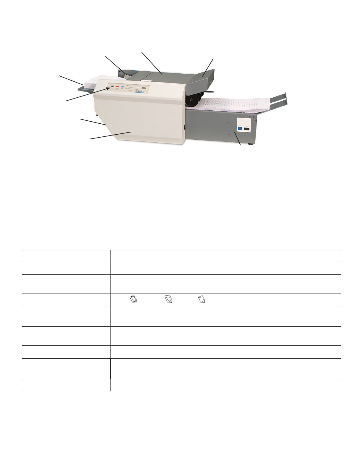
DESCRIPTION
Top Cover
Paper Side Guides
Feed Table
Control Panel
Lower Fold Plate
Operator Side Cover
FUNCTION
The 2002 / 2032 folds and seals pressure sensitive forms with pre-applied glue lines into mail ready pieces.
Numerous folds using several different paper sizes can be processed to meet your needs. For congurations
and paper sizes see specications.
Upper Fold Plate
Optional 18” Conveyor
SPECIFICATIONS
Speed 2002 / 2032: Standard Mode: Up to 8,000 / 11,000 per hour, depending on fold type
Hopper Capacity 2002 / 2032: Up to 250 / 350 sheets of 24# (90gsm) pre-glued forms
Paper size: Min: 3.5” X 5” (88.9 W x 127 L mm)
Max: 12.25” X 18” (311 W x 457 L mm)
Pre-Marked fold types: Letter , Zig-Zag , Single
Pre-Marked Paper Sizes: FD Model: 11”, 14”
FE Model: A4
Dimensions:
Dimensions w/ Conveyor
Weight: 90 lbs (40 kg)
Power: FD Model: 120 volts A.C., 50/60 Hz, 3.5 amps.
Safety Certications: UL Approved & CE Applied for
25.75” L x 16.5” W x 14.25” H (65 L x 42 W x 36 H cm)
46” L x 22” W x 14.25” H (117 L x 56 W x 36 H cm)
FE Model: 220 volts A.C., 50/60 Hz, 3.5 amps
1
Page 6
UNPACKING
Check package for shipping damage. If there is shipping damage, do not discard the box.
1.
Remove the machine and packed components from the box. Upper and lower fold plates, jam Clearing Handle
2.
(located under the top cover) and power cord.
CAUTION: Two people must lift the machine from the box.
Place the Pressure Sealer on a solid stand.
3.
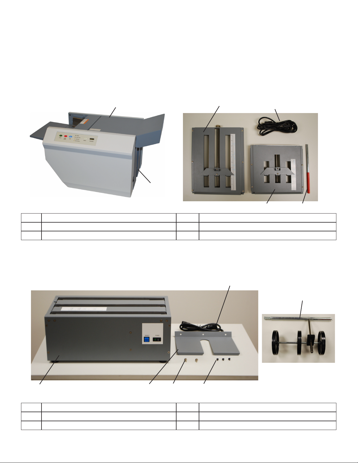
2002 / 2032 & COMPONENTS
1
2
1 2002/2032 4 Power Cord
2 Catch Tray 5 Jam Clearing Tool (ships installed)
3 Upper Fold Plate 6 Lower Fold Plate
3 4
6
OPTIONAL CONVEYOR COMPONENTS
5
5
1
1 Conveyor 4 Extension Tray Mounting Screws
2 Extension Tray 5 Power Cord
3 Mounting Shoulder Bolts 6 Out-feed Wheels
2 3 4
2
6
Page 7

CONTROL PANELS
3 84
1
6
No. NAME FUNCTION
1 Start Button
2 Stop / Reset Button
3 Jog Button Allows one form to feed at a time. Used to set fold plates
4 Power Lights up when the power is on
5 Cover Open Lights up when a cover is open
Press to start
Press to stop / Press to clear “fault” light
7
5
92
6 Paper Out Lights up when paper needs to be loaded
7 Fault Detect Light comes on if there is a paper jam
8 Reset Button Resets the counter
9 Counter Shows the number of documents processed
Optional Conveyor Controls
1
No. NAME FUNCTION
1 Runout Button
2 Power Button
Advances forms on the conveyor when pushed.
Turns the power on. When the power is on the green light is illuminates, the
conveyor advances using a photo-eye
2
3
Page 8

SETUP
Installing Upper and Lower Fold Plates, and
Power Cord
1. Be sure the plate sets rmly on the locating pins
(Fig 1a & 1b). Lift the top cover and slide the upper
fold plate under the top cover pins onto the fold
plate pins. Push down on the fold plate to lock it in
position.
2. Lift the In-feed extension tray and lock it into place.
Then slide the bottom fold plate up and in until it
meets the rear locating pins then push down to set in
place.
Upper Fold Plate Pins
Fig. 1a
Lower Fold Plate Pins
Top Cover Pins
Locating Pins
In-feed extension tray
3 Plug the power cord into the left receptacle on the
back side of the machine (Fig 1c).
Fig. 1b
Locating Pins
Fig. 1c
4
Page 9

Installing Optional Conveyor
1. Assemble the conveyor. Attach the extension tray
to the end of the conveyor using the three extension
tray screws (Fig 2a).
2. Insert power cord to receptacle on the underside of
the conveyor (Fig 2b)
3 Remove catch tray and install the mounting shoulder
bolts into the two screw holes (Fig 2c).
4 Open the top cover of the sealer and remove the
top fold plate. Then slide the conveyor into position
aligning the keyholes on the back of the conveyor
with the shoulder screws, slide in and down to lock
into position.
Fig. 2a
Fig. 2b
Fig. 2c
Mounting Screws
Shoulder Screws
5. Install the out-feed nip wheels into the two holes
located at the out-feed of the sealer (Fig 2d). Insert
the side of the rod with the spring rst, push in and
then insert the other side. Reinstall the top fold plate
and close the top cover.
6. Plug the conveyor into the right receptacle on the
back of the 2000 / 2032 (Fig 3).
Fig. 2c
Fig. 3
Spring
5
Page 10

OPERATION
1. Place power switch in the “ON” position.
2. After determining the fold type (see pg 6
“Determining Fold Type”) set the Upper and Lower
fold plates.
To set the fold stop position, squeeze the fold stop
lever and move the fold stop to the desired location
on the upper and lower fold plates(Fig 4). Align the
pointed part of the stop plate with the desired marks
on the decal and release the lever. Fine adjustments
can be made with the adjustment knob at the end of
the plate (Fig 5).
NOTE: When doing a “Half” fold, remove the bottom
fold plate, turn it 180 degrees and insert with the fold
deector leading (Fig 6). The plate must be rmly
reinstalled on the locating pins.
Fig. 4
Fig. 5
5a. Set the catch tray (See step 5b if using a conveyor).
Slide the catch tray in or out to align the appropriate
fold/form setting on the “Fold/form size decal” with
the alignment decal located on the non-operator side
frame
(Fig 7a).
5b. Set the conveyor out feed wheels. Align the center of
the out-feed stacker wheels with the appropriate fold/
form setting on the “Fold/form size decal” (Fig 7b).
Fig. 6
Fig. 7a
Fold Deector
Alignment Decal
Fold/Form Size Decal
Fig. 7b
Fold/Form Size Decal
6
Page 11

5. Set the paper side guides for the forms being used
and lock in position (Fig 8a).
Place a form between the side guides. Adjust the
side guides by loosening knobs on top, then sliding
them toward or away from each other so that the
form is snug but still lies at.
Leave equal spacing between the guides and side
frame on both sides to help ensure that the forms
feed squarely into the pressure sealer (Fig 8b).
Paper Side Guides
Fig. 8a
6. Lift the in-feed tray lever, then neatly stack paper on
the in-feed tray under the feed tires and release the
tray lever (Fig 9).
7. Press the “Jog” button on the control panel to test the
folds. Adjust as needed.
8. If the fold is skewed use the skew adjustment knob
to make corrections (Fig.10).
9. When you’re satised with the test folds, press the
“Start” button to operate the machine.
Fig. 8b
Fig. 9
Equal spacing between side frame and
guides on both sides
In-feed Tray Lever
Fig. 10
Skew Adjuster
7
Page 12

DETERMINING FOLD TYPE
Two Standard Folds 11” “Z” & 11” “C”
Leading glue edge
Glue
Glue
Glue
11” “Z” Fold
11” “Z” Fold
Leading glue edge
Glue
11” “C” Fold
11” “C” Fold
8
Page 13

SETTING CUSTOM FOLDS
Example 1: Uneven “Z”
1. Measure the length of panel “A”
2. Adjust the upper fold plate so that the fold stop lines up
with the measurements of the panel “A” i.e. if panel “A”
is 5 1/4” long slide the stop plate up or down so that it
lines up with the 5 1/4” mark on the fold plate.
3. Measure the length of panel “B”
4. Adjust the lower fold plate so that the stop plate lines
up with the measurement of panel “B”
5. Load forms and press test. If folds are too long or too
short adjust accordingly.
Example 2: Uneven “C”
1. Measure the length of panel “A” & “B”
2. Adjust the upper fold plate so that the fold stop lines up
with the measurements of panel “A” & “B”. i.e. if panel
“A” & “B” are 10 1/2” long slide the stop plate up or
down so that it lines up with the 10 1/2” mark on the fold
plate.
Panel A
Panel B
Panel A
Panel B
3. Measure the length of panel “B”
4. Adjust the lower fold plate so that the stop plate lines up
with the measurement of panel “B
5. Load forms and press test. If folds are too long or too
short adjust accordingly.
9
Page 14

OPERATOR MAINTENANCE
1. It is recommended to let forms cool for one-half hour, from the laser printer, before folding. This allows toner to set
on the forms and static electricity to discharge. A 402 Series Jogger is recommended for best results. The Jogger
squares the forms and dissipates heat and static electricity created by laser printers.
2. If toner builds up on the metal sealer rollers clean the rollers with a lint-free cloth dampened sparingly with a mild
household cleaner.
3. Clean in-feed tires and fold rollers with Formax recommended roller cleaner & rejuvenator to remove paper dust and
toner. A Formax Cleaner Kit is available from your dealer. A damp cloth with water is the best alternative.
CAUTION: Do not use any chemicals other than the roller cleaner & rejuvenator or water.
METAL SEAL ROLLERS CLEANING PROCEDURE:
1. Make sure machine is turned off and unplugged. All
folders have four (4) rubber rollers (Fig. 11).
2. Open the top cover and remove the upper fold plate to
access the seal rollers.
3. Using a mild household cleaner, spray a new cotton
cloth until the cloth is saturated. Wipe the wet cloth in
a back and forth motion and rotate the rollers by hand
making sure to clean the entire surface of the seal
rollers. Next use a dry cloth and wipe off excess toner.
The cloth should be covered with black toner surplus
from cleaning the rollers.
4. Run 10-15 sheets of blank copy paper through the
folder/sealer to ensure all cleaner has been removed
from the fold rollers. Running blank sheets will remove
any excess residue of cleaner on the rollers.
Fig. 11
Seal Rollers
IN-FEED TIRES AND FOLD ROLLERS
CLEANING PROCEDURE:
1. Make sure machine is turned off and unplugged. The
sealers have three (3) feed tires and four (4) rubber
rollers (Fig. 12a & 12b).
2. Open the top covers and remove the upper and lower
fold plates to access the tires and rollers.
3. Using Formax roller cleaner, spray a new cotton cloth
until the cloth is saturated. Wipe the wet cloth in a
back and forth motion and rotate the tires / rollers by
hand making sure to clean the entire surface of the
feed tire / fold rollers. Next use a dry cloth and wipe off
excess toner. The cloth should be covered with black
toner surplus from cleaning the tires / rollers.
4. Run 10-15 sheets of blank copy paper through the
folder/sealer to ensure all cleaner has been removed
from the fold rollers. Running blank sheets will remove
any excess residue of cleaner on the rollers.
10
Fig. 12a
Fig. 12b
Feed Tires
Fold Rollers
Page 15

CLEARING PAPER JAMS:
WARNING: Turn off machine and unplug cord from its
receptacle
1. If a jam occurs between the metal rollers remove any
remaining forms from the hopper. Open the top cover
and remove the upper fold plate. Remove the jam
clearing handle (located under the upper fold table)
apply the handle to the upper metal roller (Fig13) and
turn clockwise until the paper jam is clear. NOTE: Do
not turn the roller counter-clockwise to force the forms
to exit: rollers may be damaged. Remove the damaged
form, return tool to holder and reinstall upper fold plate.
2. Reinstall cover and press the black reset button
(Fig14).
Fig. 13
Fig. 14
Reset Button
11
Page 16

TROUBLE-SHOOTING
TROUBLE POSSIBLE CAUSE REMEDY
Control panel lights are
not illuminated.
No power at the wall outlet.
No power to the machine inlet.
Check wall outlet.
Check power cord for frayed/broken
wires.
No power to the control panel.
Internal electrical failure
“Cover Open” light is on. Cover open
Magnetic switch is broken.
“Paper Out “ light is on. In-feed tray is empty. Place documents on the in-feed tray.
“Fault detect” light is on. Paper misfeed
Paper jammed at exit of folder.
Black marks on the folded
paper.
Folds are off. Fold plate(s) need to be
Fold is skewed. In-feed tray is out of
Documents are wrinkled
or crunched.
In-feed tires, separator, fold
rollers and/or sealer rollers are
dirty.
adjusted
adjustment.
Paper side guides need to be
reset.
Fold plates are not inserted
correctly.
Press the button on the circuit breaker.
Call for service
Close cover
Call for service
Reload paper and press “Reset”.
Remove paper and press “Reset”.
Clean the parts with approved roller
cleaner and rejuvenator.
Adjust fold stop and or ne tuning knob
Turn skew adjuster knob to remove the
skew.
Loosen side guides rest and lock into
position, side guides should be evenly
balanced
Remove and reinstall fold plates. Be
sure they’re properly positioned.
Piece of paper or other material
is stuck in the fold plate.
In-feed tray lever does
not work
Double feeding forms Documents stuck together
Not feeding documents Feed tire dirty
Broken spring Call for service
Feed tire or separator worn
Feed tire or separator worn
Remove object from the fold plate.
Jog forms to remove static electricity.
Call for service
Clean feed tire
Call for Service
12
Page 17

 Loading...